1
PAR T S
•
ACCESSORIES
•
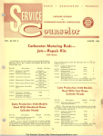
PRODUCT
PACKARD DIVISION
OF
STUDEBAKER-PACKARD CORPORATION
VOL. 29, NO. 10
OCTOBER, 1955
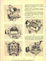
WCFB Carter Carburetor
Model 2394 S
Anew 4-barrel Carter Carburetor, known as the
"WCFB" Carburetor, Model 2394 S, is used on 1956
Clipper Custom Models (5660).
to open. The geometry of the linkage then causes
both sets of throttle valves to reach the wide open
position at the same time.
The 4-barrel carburetor provides the advantages
of a compound installation of two 2-barrel carburetors in one compact unit. It is possible to use smaller
venturi, leaner metering rods and jets when a carburetor only takes care of speeds up to approximately
%: throttle openin~. Greater throttle opening requires additional al£ and fuel which is supplied by
the additional 2-barcelsi therefore, the overall performance and efficiency are improved.
The auxiliary throttle valves permits the use of
larger secondary ve nturi for improved performance
and smoother seco ndary operation. Its shaft is
counterweighted and the valves are offset mounted.
Air velocity through the carburetor controls the
position of th e auxiliary throttle valves according to
engine requir ements and no service adjustments are
required.
When the accelerator is fully depressed, only the
primary high-speed circuit will function until there is
sufficient air velocity to overcome the weight on the
aux iliary throttle lever and open the auxiliary throttle
valves. When this occurs, fuel will also be supplied
through the secondary high-speed circuit.
.The 4-barrel carburetor is divided into a primary
sectiml 411d a secondary section.
The primary sectiml is composed of the 2-barreled
forward half of the assembly. This section is essentiallya complete 2-barrel carburetor containing a float
system, low speed system, high speed and power
system and accelerating system. ThIS section also includes tbe climatic control (automatic choke) mechanism.
In other words, without auxiliary throttle valves, if
the secondary throttle valves are opened at low car
speeds, the air intake is greater than is required creating an undesired mi xture. With the auxiliary throttle
valves gradually opening with the air velocity, the
proper mixture can be maintained from low to high
car speeds.
The secondary section includes the 2-barreled rearward half of the carburetor assembly. This section is
essentially a supplementary 2-barrel carburetor which
cuts in to assist the primary section when a greater
throttle opening or a greater engine load is reached.
This section contains a float system, a high speed
system (no metering rods). It has a separate set of
throttle valves and a set of auxiliary valves which are
located in the barrels above the throttle valves.
The following paragraphs describe the adjustments
necessary to . service the 4-barrel carburetor. It is
important that the adjustments be performed ;11 the exact
sequence given:
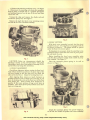
1. Remove the metering rods dust cover, "A" Fig. 1.
Disconnect the metering rods from the vacumeter
link by using a scratch awl or a pointed instrument
and pushing outward on the eye of the rod and then
extract the rod.
The primary throttle valves are operated by the
accelerator pedal and the connecting tbrottle linkage.
The seco"dary throttle valves are operated by the
primary throttle valve shaft through delayed action
linkage which permits an approximate %: opening of
the primary valves before the secondary valves start
Unsnap the clips and remove the choke rod and the
accelerator pump rod, "B" Fig. 1.
47
The Packard Library (http://www.thepackardlibrary.com)
Remove the air horn and floats assembly. NOTE: 7
long screws, "A," 8 short screws, "B," and 1 medium
length screw, "C," attach the air horn to the carburetor
main body as indicated in Fig. 2.
CAUTION: Under no circumstances should the
discharge nozzles or the anti-percolator well plugs
be removed when servicing this carburetor, indicated
by "Arrows" in Fig. 3.
2. Float Settings: Do not mix up the floats or float
needles from one side to the other as float needles and
seats are mated and flooding may occur if the needles
are not installed in their original seats. The float
level adjustment is made with the bowl cover (air
horn) gasket removed.
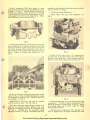
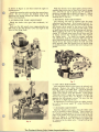
A. Float Level: Two separate float adjustments must
be made-lateral and vertical.
Fig. 1
Fig. 4
Fig. 2
Lateral Adjustment: With bowl cover assembly
inverted and float resting on seated needle, place
float gauge under floats with notched portion of gauge
fitted over edge of casting. Side of floats should just
clear the vertical uprights of the float gauge, " B" Fig.
4. Adjustment is made by bending arms of floats.
Fig. 3
Fig. 5
48
The Packard Library (http://www.thepackardlibrary.com)
assembly to the carburetor body, and secure it with the
screws, "A,~' "B," "C" Fig. 2.
Vertical Adjustment: With float gauge in same
position, floats should just clear the horizo ntal section
of gauge, "A" Fig. 4. Vertical distance between top
of float and machined surface of bowl cover must be
VB inch (gauge T109-232) fo r primary floats and 3/ 16
inch (gauge T109-222) for secondary floats. Adjust
by bending float arms as shown in Fig. 5.
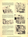
3. Acce lerator Pump Adj ustment:
A. Block choke valve open with cardboard, "A"
Fig. 9.
Fig. 6
•
B. Float Drop Adjustment: With the bowl cover (air
horD) supported in an upright position, the distance
from the machined surface on the bowl cover to the
top of the secondary floats should be 17/ 32', Fig. 6.
The distance for the primary floats should be 15/ 32#,
Fig. 6. Adjust by bending tang indicated by "A,"
Fig. 5.
Fig. 8
B. Back off idle speed screw "B" approximately
two full [urns so that the throttle valves seat tight in
the bores of the flange body. Be sure pump connector
links is in outer hole (long stroke) of pump arm "c."
,
Fig. 7
Be sure to install the accelerator pump check need le
shown in Fig. 7, before installing the pump jet gasket,
jet housing and retainer screw. Install a new bowl
cover gasket, "A" Fig. 8.
Fig. 9
IMPORTANT: Vacllmeter lillk mllst be installed
with lip toward air hom. (See " D," Fig. 2)
C. Hold straight edge across top of dust cover boss
at pump arm.
The flat o n top o f the pump arm "D"
should be parallel to straight edge, "E" Fig. 9. Adjust
by bending pump rod at lower angle "F," using
bending tool T109-213 .
Place the accelerator pump plunger spring in its
well and the vacumeter piston spring in its well.
Attach the vacumeter piston to the vacumeter link,
"B" Fig. 8. Carefully start the accelerator pump
plunger in its bore, " C" Fig. B. Install the bowl cover
4. M etering Rod Adjustment: Tbe metering rods
must be adjllsted after tbe pump adjllstme11t bas been
49
The Packard Library (http://www.thepackardlibrary.com)
made. First, loosen the screw, "A" Fig. 10. With the
idle speed screw backed out and the throttle valves
seated in the bores of the flange body, press down on
the vacumeter link with a scale "B" until the metering
rods bottom. While holding the rods in this position,
revolve the clamp "C" forward away from the air horn
Fig. 12
Fig. 10
until lip of clamp contacts the vacumeter link, then
tighten the clamp screw. To check for proper metering rod adjustment, hold the vacumeter link and rods
at their bottomed position and open the throttle.
There should be no lost motion before the link and
rods move upward when the throttle lever is moved
from its closed position. Install the dust cover using
a new gasket.
Fig. 13
Fig. 11
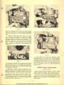
5. Bowl Vapor Vent Adjustment: With the throttle
valves closed and the choke blocked open, the vapor
vent should open .062". Using a feeler gauge measure
between the metering rod dust cover and the lower
edge of the vapor vent cover Fig. 11. Adjustment of
the vapor vent valve can be made by bending tbe tang
on the vapor arm. "Insert Fig. 11."
6. Fast Idle Adjustment:
A. Loosen choke lever clamp screw on choke shaft,
"A" Fig. 12. Insert .020" wire gauge Tool No. T109·
29 between lip of fast idle cam and boss of flange
casting, " B" Fig. 12. Hold choke valve tightly closed
and take slack out of linkage by pressing choke lever
toward closed position, hold in place and tighten
clamp screw "A."
B. With choke valve tightly closed, adjust fast idle
adjusting screw, "A" Fig. 13, until a .023" wire gauge
Tool No. T109·189 can be inserted between the rear
Fig. 14
50
The Packard Library (http://www.thepackardlibrary.com)
Fig . 15
Fig. 17
side of the primary throttle valves and the throttIe
body bore, " B" Fig. l3. Be sure fast idle adjusting
screw is on high step of cam while making this adjustment.
7. Un loader Adjustment: First hold the choke
valve wide open, then push the throttle wide open,
Fig. 14, release the choke so it will close. While
holding the throttle wide open, there should be 3/ 16"
clearance (Tool No. T109·28) between the upper
edge of the choke valve and the inner wall of the air
horn. "AU Fig. 15. Bend unloacler lip "B" to get the
proper cho~e valve clearance. Use bending Tool
T109-41.
Fig. 18
Fig . 16
8. Secondary Throttle Lever Adjustment: Primary
and secondary throttle valves should reach wide open
position at the same time. To adjust, bend operating
rod at upper angle indicated by "arrow," Fig. 16. Use
bending Tool T109-213.
9. Secondary Throttle Lock-out Adjustment: The
secondary lock-out is provided to prevent the possibility of opening the secondary throttle valves with
the choke closed or partially closed with a cold engine.
A. Crack throttle valves and hold choke valve
tightly closed. Then close throttle. Tang "A," Fig.
17, on secondary throttle lever should freely engage
in notch of lock-out lever . If necessary to adjust, bend
tang on secondary throttle lever.
B. Hold choke valve in wide open position. Open
primary throttle valves all the way. With carburetor
in upright position, the lock-out lever should fall free
allowing secondary throttle valves to be opened before primary throttle valves are fully open. If necessary, bend tang, "A" Fig. 18, on secondary throttle
lever to provide clearance fo r proper operation of
lock-out lever.
WGD Carter Carburetor
Model 2393 S
A new 2-barrel Carter Carburetor, known as the
"WGD" carburetor, Model 2393 S, is used on 1956
Clipper Deluxe and Clipper Super Models (5640).
The following paragraphs describe the adjustments
necessary to service th e 2-barrel carburetor. It is
important that the adjustments be performed ill the exact
sequerlce given:
The Packard Library (http://www.thepackardlibrary.com)
1. Remove the metering rods dust cover, "A" Figure
Disconnect the metering rods from the vacumeter
Jink by using a scratch awl or a pointed instrument
and pushing outward on tbe eye of the rod and then
extraCt the rod.
1.
Unsnap the clips and remove the choke rod and
accelerator pump rod, "B" Figure 1.
Remove the eight fuel bowl cover retaining screws
and Jift off tbe cover and float assembly.
Fig. 3
3. FLOAT SETTING
With bowl cover assembly inverted, the float level
should be set to 3/ 16" using fioat level gauge TI09-28
as shown in Figure 2. The gauge should be placed
under the float at its lowest point.
If adjustment is necessary, bend the small lip in the
V.shaped section of the float arm near its pivot point.
Do not bend the arm.
Before installing the bowl cover assembly, make
sure that the accelerator pump check needle is prop·
erly installed "See Figure 3."
Place the vacumeter piston spring in its well as
shown in Figure 3.
Fig. 1
CAUTION: Under no circumstances should the
discharge nozzles or the anti· percolator well plugs
(the plugs at each side of the pump jet housing) be reo
moved when servicing this carburetor.
2. FLOAT ALIGNMENT
Check float alignment before setting the float level.
Side of fioat should be parallel to the outer edge of the
air horn casting so that the float will not touch the
sides of the fuel bowl. Adjust loy bending fioat lever.
After aligning float, remove as much clearance as
possible between arms of float lever and lugs on air
horn by bending the arms of the float lever at the float
lever binge pin. Arms of float lever should be as
parallel to the inner surfaces of lugs on air horn as
possible. Float must operate freely withollt excess clear·
ance 011 its hblge pin.
Fig. 4
Attach the vacu.m eter piston "see arrow" Figure 4,
to its link and install the gasket and cover assembly
Fig. 2
52
The Packard Library (http://www.thepackardlibrary.com)
as shown in Figure 4, and then install the eight re·
taining screws.
Install the metering rods reversing the removal procedure. Be sure to place tbe hooked ends of the
metering rod spring around the shank of the rods
before inserting them.
With the throttle valves held tightly closed, hold a
straight edge across top of dust cover boss at pump
arm. The flat on top of pump arm '"B" should be
parallel to straight edge as shown in Figure 5. Adjust
by bending pump rod at the upper angle '"C" using
bending tool T·I09·213.
4. ACCELERATOR PUMP ADJUSTMENT
5. METERING ROD ADJUSTMENT
The metering rods must be adjusted after the pump
adjustment has been made. First, loosen the screw" AU
Figure 6. With the idle speed screw backed out and
th e throttle valves seated in the bores of the flange
body, press down on the vacumeter link with a scale
or small screw driver until the metering rods bottom.
While holding the rods in this position, revolve the
clamp "B" forward away from the air horn until lip
of clamp contacts the vacumeter link, then tighten
the clamp screw. To check for proper metering
rod adjustment, hold the vacumeter link and rods at
their bottomed position and open the throttle. There
should be no lost motion before the link and rods
move upward when the throttle lever is moved from
its closed position. Install the dust cover using a new
gasket.
Block the choke valve open with cardboard, "A"
Figure 5.
Back out the idle speed screw approximately two
full turns so that the tbrottle valves seat tight in the
bores of the flange body.
Fig. 5
Fig . 7
6. FAST IDLE ADJUSTMENT
This adjustment mllst be mad e before the 1m/onder adjustment. Remove the choke thermostatic coil and
housing, gasket, and baffle plate. Crack the throttle
valve, then close the choke valve. While holding the
choke valve closed, close the throttle. Using gauge
TI09-189 (.024" ), check the clearance between the
throttle valve and the bore "A" Figure 7, on the side
opposite the idle mixture screws. Be sure that fast
idle link is on high step of cam.
lf adjustment is necessary, be nd the choke connector rod at the lower angle "B" using bending tool
T-I09-213.
7. UNLOADER ADJUSTMENT
Hold the throttle wide open, close the choke valve
as far as possible without forcing. There should be
Ys" clearance, using gauge TI09-36, between the top
edge of the choke valve and th e inner wall of the air
horn, " A" Figure 8 . If adjustment is necessary, bend
the choke trip lever arm, "B" Figure 8, to obtain the
Ys" clearance at the choke valve. Using bending tool
T-I09-213.
Fig. 6
53
The Packard Library (http://www.thepackardlibrary.com)
from the carburetor body. In the event that the assembly sticks, carefully tap it from the body from above
with a long punch. Be careful to not distOrt the valves.
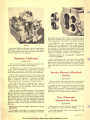
CAUTION: Do not disassemble the auxiliary
throttle valves or change the screw setting indicated
by the arrow in the illustration. The spring tension is
set correctly at the factory; any change in calibration
w ill completely upset the operation of the secondary
side of the carburetor. If wear or damage has occurred
replace the complete auxiliary valve assembly.
Fig. 8
Install the choke thermostatic coil and housing, (he
baffle plate should be installed ahead of the gasket.
The coil housing should be set two points rich before
the retaining screws are tightened.
INSTALLATION OF AUXILIARY THROTTLE
VALVE ASSEMBLY
Rochester Carburetor
Invert carburetor body and press the auxiliary
throttle valve assembly into place in the casting, mak.
ing sure that it does nOt project below the carburetor
body. Be sure that the assembly is installed with the
valve shaft below the valves as shown in the illustration.
Model 4GC
The 4-barrel Rochester Carburetor, Model 4GC,
is used on 1956 Packard Models (5680).
All adjustments are made in the same manner and
to the same measurements as described in Service
Counselor Vol. 29, No.2. February, 1955 and in the
Fuel and Exhaust Section of your new Service Manual.
Service Manual- Electrical
Section
NOTE: The Atmospheric Idle Vent has been elimi·
nated, "Shown in Fig. 9 in the Service Counselor and
Fig. 29 in the Service Manual." Therefore, no adjustment is required. The vent contace afm has been
bent away so it will not contact and open the valve.
(Correction)
Please make the following correction in the Electrical Section of your new 55th Series Service Manual.
The 1956 Model 4GC Carburetor has a pair of
spring-loaded, velocity-operated auxiliary throttle
valves located in the secondary bores above the
secondary throttle val yes.
On page 39 under Trouble Shooting and Corrective
Measures, item-IS, change the "Correction" to read,
"Polarize the generator by momentarily connecting a
jumper across from the armllture ("A") terminal to
the battery ("B") terminal on the regulator."
When air velocity is high, metering control is good
and the auxiliary valves are held open. During lowspeed wide open throttle operation, the air velocity
tnrough four bores often becomes too low to allow
good metering control; the lowered velocity allows
the auxiliary valves to close the secondary bores, thus
effectively doubling the air flow through the primary
bores. In this way. effective metering control is
possible through a wider range of wide-open throttle
operation.
,
,
Twin Ultramatic
Transmission Fluid
(Correction)
Please refer to your Service Counselor Vol. 29,
No.8, August, 1955, on the above subject.
REMOVAL OF AUXILIARY THROTTLE VALVE
ASSEMBLY
The assembly will usually be removable by grasping
with the ·thumb and forefinger and lifting the assembly
In the last paragraph of the article, change the AQ.
AFT to read AQ·ATF.
54
The Packard Library (http://www.thepackardlibrary.com)
P!'! I NT E D I N U.S.A.