1
FUEL SYSTEM
14-1
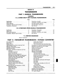
G R O U P 14
FUEL SYSTEM (PUMP, CARBURETOR, TANK)
CONTENTS
PART 1 — W W C 3 Series Carbureter
Page
Page
Disassembling the Carburetor
Inspection and Reassembly
5
7
Carburetor Adjustments.
Automatic Choke (Well Type)
10
14
PART 2—BBD Series Carburetor
Disassembling the Carburetor.
Inspection and Reassembly....
Carburetor Adjustments
16
17
19
Automatic Choke (Well Type)
Closed Crankcase Vent System
Throttle Linkage
.. . . . . . . . . .
23
23
23
PART 3—AFB Series Carburetor
Disassembling the C a r b u r e t o r . . . . . . . . . . . . . . . . . . . . - 26
Inspection and Reassembly
29
Carburetor Adjustments.
32
Automatic Choke (Well Type)
Closed Crankcase Vent System.
Throttle Linkage
35
36
36
PART 4—Firepower 390 FUEL AND INDUCTION SYSTEM
Intake Manifolds
Throttle Linkage
Disassembling the Carburetor (AFB).
38
41
43
Inspection and Reassembly
Carburetor Adjustments.
45
48
PART 5—Fuel Pump and Tank
Fuel Pump Operation
Testing the Fuel Pump
,.
50
50
Fuel Tank—Removal
52
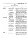
PART 6—Service Diagnosis
Carburetor
55
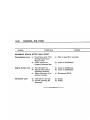
SPECIAL TOOLS
. Bending Tool
Wire Gauge .020" Secondary Throttle Lever
14" Gauge, Choke Unloader
14" Gauge, Fast Idle Cam Positioning
(Tl09-238, W Manual Trans.)
^ 4 " Gauge, Fast Idle Cam Positioning
Tl 09-32
%A
Gauge, Unloader Adjustment
VB" Gauge, Vacuum Kick Adjustment
T109-36
Bending Tool (Fast Idle and Unloader)
Tl 09-41
Tl09-58. , . . .Screw Driver Bit
Screw Driver Bit
Tl 09-59
Tl 09-80.^ . ..Gauge, %" Unloader
T109-106. . ,. % 2 " Gauge, Vacuum Kick Adjustment
(Manual Trans.)
T109-22
Tl 09-29
Tl 09-31
Tl 09-31
Y
,F
% 4 " Gauge, Fast Idle Cam Positioning
Tl 09-39
T109-166. . . . AA" Gauge, Vacuum Kick Adjustment
(Auto. Trans.)
T109-173. . . .Main Metering Jet (Removal and Installation)
T l 0 9 - 2 1 3 . . . .Bending Tool
T109-214. , . . Bending Tool
T109-282. . . . 14" Gauge, Float
T109-287S. . .Elevating Legs
, Repair Stand
C-3400
Power Bypass Jet (Removal and Installation)
73598
. . Bending Tool
73605
. . % 2 " Gauge, Float
73725
. I 4 " Drill, Bowl Vent Valve
No. 47
1
1]
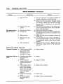
SPECIFICATIONS
MAKE
Stromberg
Boll & Ball
Carter
Carter
Carter
TYPE
Dual Downdraft
Dual Downdraft
4 Barrel
Downdraft
2-4 Barrel
Downdraft
4 Barrel
Downdraft
CARBURETOR MODEL
ENGINE DISPLACEMENT
(Cu.ln.)
WWC3-244
Manual Trans.
WWC3-242
Auto. Trans.
BBD-3685S
AFB-3614S
AFB-3505S
AFB-3615S
AFB-3644S
361
361
383
413
413
413
VC-2 with
Firepower 305
VC-1 Police
VC-2 Hi-Perf.
with
Firepower 360
VC-2 with
Firepower 390
VC-3 with
Firepower 340
VY-1 with
Imperial V-8
VC-1 with
Firebolt 265
CAR MODEL ENGINE APPLICATION
BORE
Primary
Secondary
' \W
—
1W
AAAIN VENTURI
Primary.
Secondary
\W
—
1W
MAIN METERING JET
Standard
One Step Lean.
Two Steps Lean
l"yk"
3
.,
...
Part No. 388186
.061"
.061"
,059"
.059"
.057"
.057"
..
MAIN JET (Secondary)......
—
—
028" x .055"
.028" x .055"
LOW SPEED JET (Primary)
—
—
STEP UP WIRE DIAMETER
(Standard).
(2 Stage)..
—
—
POWER JET
.. .
STEP UP ROD (2 Stages)
Standard.
(1 Size Lean).
(2 Sizes Lean). . . . . . . . . . . . . .
•
•
—
—
—
—
l /fc"
1^6"
1516"
.089"
.089"
.067"
.082
.089"
#120-248
#120-249
#120-250
w
.067"
#65-.035"
#65-.035"
#65-.035"
16-217
16-165
16-159
16-118
16-119
16-50
16-165
16-160
16-173
75-1598
.031" x .026"
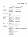
SPECIFICATIONS— (Continued)
ADJUSTMENTS
Accelerator Pump Travel
Accelerator Pump Travel (Blades Fully Closed).
Accelerator Pump (Top of Plunger to Air horn)
Float Setting
Float Drop
•
Bowl Vent Valve (Curb Idle)
Vacuum Kick (Drill Size)
Choke Unloader
Idle Mixture Screws (Turns Open)
Idle Speed RPM (Curb Idle)
(Air Conditioning on) RPM
Fast idle Speed R P M . . . . . .
Fast Idle Cam Position Adjustment. . . . . . . . . .
Secondary Throttle Lever Adjustment
Secondary Throttle Lockout Adjustment
Velocity Valve
—
—
—
—
—
—
w
w
w
VA"
—
w
W
—
"AA"
Mi."
'HA"
VA"
w
w
VA
l'/2
VA"
500
500
600
500
500
700
500
500
700
Vi"
—
—
—
—
3
/4"
—
V*"
%"
1-2
500
500
700
—
1-2
700
500
1400
—
.020"
—
.020"
Free
.020"
—
Well
Thermostatic
Coil Spring
On Index
Hand
Well
Thermostatic
Coil Spring
2 Notches Rich
——
1-2
500
500
700
CHOKE
Well
Thermostatic
Coil Spring
2 Notches Rich
Weil
Thermostatic
Coil Spring
1 Notch Rich
Type...
Control.
Setting.
FUEL PUMP
V C - 1 , V C - 2 , V C - 3 , VY-1
Make....
Model
Type
/
C a r t e r
•
•
•
,
Number of Valves
Driven by
Pump Pressure
i
•
W-3672S
Diaphragm
t/i
<
in
—I
m
2
Camshaft
•
3 Vi to 5 psi
4^
i
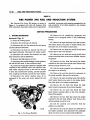
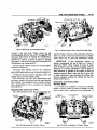
14-4
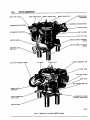
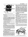
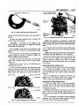
WWC3 CARBURETOR
BOWL VENT VALVE,
L O N G STROKE SLOT
NORMAL STROKE SLOT
SHORT STROKE SLOT
CHOKE VACUUM
DIAPHRAGM
DIAPHRAGM PLUNGER (STEM!
A C C E L E R A T O R P U M P LEVER
VACUUM HOSE
ACCELERATOR PUMP R O D
F A S T IDLE R O D
FAST IDLE C A M
CURB IDLE S P E E D A D J U S T I N G
SCREW
THROTTLE LEVER
FAST IDLE S P E E D A D J U S T I N G
SCREW
ELEVATING LEGS
(SET O P 4)
C H O K E O P E R A T I N G LINK
FAST IDLE A D J U S T I N G S C R E W
C H O K E LEVER
FUEL INLET FITTING
MAIN B O D Y
IDLE MIXTURE S C R E W (2)
CHOKE VACUUM
DIAPHRAGM
DISTRIBUTOR V A C U U M
A D V A N C E TUBE FITTING
CLOSED CRANKCASE
V E N T FITTING
THROTTLE B O D Y
64x22
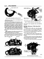
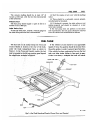
Fig.
Carburetor Assembly (WWC3 Series)
r
WWC3 CARBURETOR
14-5
FUEL SYSTEM
PART 1
MODEL WWC3 STROMBERG CARBURETORS
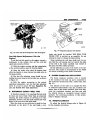
The WWC3 Series Stremberg carburetor (Pig. 1)
is a dual throat downdraft type, with each throat
having its own idle system, main metering system
and throttle valve. The idle and main metering system are supplemented by the float system, the accelerating system and the power system.
The carburetor incorporates an idle system vent,
operated from the throttle linkage, a double venturi
cluster which in addition to the small venturi, also
includes the discharge nozzles, the main discharge
tubes and the idle tubes in a single assembly. Dirt,
dust, water and gummy deposits are some of the
main causes for improper carburetor operation.
Proper cleaning, however, and the installation of new
parts, where required, will return the carburetor to
its originally designed performance.
When overhauling the carburetor, several items of
importance should be observed to assure a good job.
(1) All parts (except the diaphragm assembly)
should be carefully cleaned in a suitable solvent, then
inspected for damage or wear.
(2) Use air pressure only, to clean the various
orifices and channels.
(3) Replace questionable parts with NEW ones.
Always use a complete kit when overhauling the carburetor. Using the code number stamped on the air
horn, adjacent to the fuel inlet, refer to the parts
catalog and order the correct repair kit for the carburetor being worked on.
SERVICE PROCEDURES
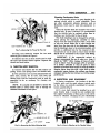
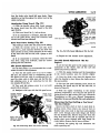
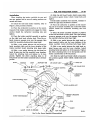
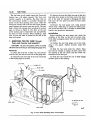
1. DISASSEMBLING THE CARBURETOR
(Figs. 1 and 2 )
(1) Install four elevating legs, Tool T109-287S, in
the mounting flange holes in the throttle body. These
legs are used to protect the throttle valves from
damage and to provide a suitable base for working.
(2) Remove the hairpin clip that holds the pump
rod in the center slot of the pump arm. Remove rod
from slot and disengage from the throttle lever.
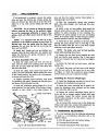
(3) Remove the hairpin clip that hold the fast idle
rod in the fast idle cam. Disengage rod from cam,
then rotate rod to disengage from choke lever.
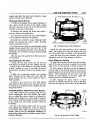
(4) Remove the three short air horn attaching
screws, then remove the two long air horn attaching
screws. Install two short screws through the main
body into the throttle body to hold the bodies together (Fig. 3).
(5) Remove the vacuum hose between the carburetor air horn and the vacuum diaphragm.
(6) Remove the clip from the choke operating link
and disengage the link from the diaphragm plunger
(stem) and the choke lever. (Refer to Fig. 1.)
(7) Remove the vacuum diaphragm and bracket assembly and place to one side to be cleaned as a
special item. A liquid cleaner other than mineral
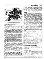
Fig. 2—-Carburetor Assembly (Disassembled View)
14-6
WWC3 CARBURETOR
Fig. 5—Removing the Vacuum Power Piston
Fig. 3—Removing the Air Horn
spirits, may damage the diaphragm material.
(8) Remove the remaining air horn attaching
screws, then lift air horn straight up and away from
main body, as shown in Figure 3.
(9) Disengage the accelerator pump-plunger from
the pump arm hook by tilting down and out from
under hook, as shown in Figure 4. Remove the compression spring.
Place the accelerator pump plunger in a jar of
clean gasoline or kerosene to prevent the leather from
drying out
(10) Remove the vacuum power piston from the air
horn, using an open end wrench and wood block, as
shown in Figure 5. (Exert sufficient pressure on end
of wrench to force piston out of its well in air horn.
This assembly is staked in the air horn and care
should be used at removal.) Discard air horn gasket.
(11) Test the freeness of the choke mechanism in
Fig. 4—-Removing the Accelerator Pump Plunger
the air horn. The choke shaft must float free to
operate correctly. If the choke shaft sticks in the
bearings, or appears to be gummed from deposits in
the air horn, a thorough cleaning will be required.
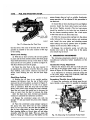
2. M A I N B O D Y R E M O V A L
(1) Remove the venturi cluster attaching screws,
the venturi cluster and gasket, as shown in Figure 6.
Discard the gasket.
(2) Remove the float fulcrum pin spring, the fuel
inlet needle valve, seat and gasket.
(3) Slide the float baffle up and out of its grooves,
and remove the float and fulcrum pin.
(4) Invert the carburetor main body and drop out
the discharge check ball from the discharge passage
(Fig. 6), and the accelerator pump inlet check ball
from the pump well.
(5) Using Tool 73598, remove the power by-pass
jet and gaskets, as shown in Figure 7.
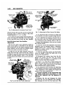
Fig. 6—Removing the Venturi Cluster
WWC3 CARBURETOR
f j g . 7 — R e m o v i n g the Power B y - P a s s Jet
(6) Using Tool T109-173, remove the two main
metering jets, as shown in Figure 8.
(7) Remove the two air horn screws used to hold
the main and throttle bodies together. Separate the
throttle and main bodies.
3 . THROTTLE B O D Y R E M O V A L
(1) Unscrew and remove the two idle mixture adjusting screws and springs from the throttle body.
(2) The carburetor now has been disassembled into
three units; namely, the air horn, main body and
throttle body and the component parts of each disassembled as far as necessary for cleaning and
inspection.
NOTE: It is usually not advisable to remove the
throttle shaft or valves unless wear or damage necessitates installation of new parts.
Fig. 8 — R e m o v i n g the Main Metering Jets
14-7
Cleaning Carburetor
Parts
The recommended solvent for gum deposits is denatured alcohol which is easily obtainable. There
are other commercial solvents, however, such as
Metalclene, which may be used with satisfactory results.
Check the throttle shaft for excessive wear in the
throttle body. If wear is extreme, it is recommended
that the throttle body be replaced rather than installing a new throttle shaft in the old body.
The choke diaphragm can be damaged by solvents.
Avoid placing the diaphragm assembly in ANY
liquid. Clean the external surfaces with a clean cloth
or soft wire brush. Shake dirt or other foreign material from the stem side of the diaphragm. Depressing the diaphragm stem to the retracted position, will
provide an additional hole for the removal of dirt.
Compressed air can be used to remove loose dirt but
should not be connected to the vacuum inlet fitting.
IMPORTANT: If the commercial solvent or
cleaner recommends the use of water as a rinse, it
should be "HOT." After rinsing, all trace of water
must be blown from the passages with air pressure.
It is further advisable to rinse all parts in clean
gasoline or kerosene to be certain no trace of moisture
remains. Never clean jets with a wire, drill or other
mechanical means because the orifices may become
enlarged, making the fuel mixture too rich for proper
performance.
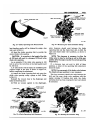
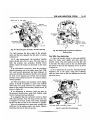
4 INSPECTION A N D REASSEMBLY
(1) During manufacture, the location of the idle
transfer ports and the spark advance control ports
to the valves are carefully established for one particular assembly (Fig. 9).
(2) If a new shaft should be installed in an old
worn throttle body, it would be very unlikely that
the original relationship of these ports to the valves
would be obtained. Changing the port relationship
Fig. 9 — P o r t s in Relation to the Throttle V a l v e s
WWC3 CARBURETOR
14-8
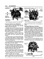
THROTTLE
BODY
THROTTLE VALVES
DRIVE PLUGS
POWER BY-PASS JET
IDLE SPEED ADJUSTING
SCREW
FAST IDLE SPEED
SCREW
THROTTLE LEVER AND
SHAFT
ATTACHING SCREWS
GASKET.
VENTURI CLUSTER
FULCRUM PIN
SPRING GASKET
FUEL INLET NEEDLE
VALVE SEAT AND GASKET
FLOAT BAFFLEv.
DISCHARGE
CHECK BALL
^
INLET CHECK BALL
(PUMP)
FULCRUM PIN
IDLE MIXTURE
SCREWS
MAIN BODY
SPRING
FLOAT
THROTTLE VALVE SCREWS
63x492
MAIN METERING JETS
PASSAGE PLUGS
60x343
Fig. 10—Throttle Body (Disassembled View)
Fig. 11—Main Body (Disassembled View)
would adversely affect normal car operation between
the speeds of 15 and 30 miles per hour. If it has
been determined, however, that a new shaft or valves
are to be installed, adhere closely to the following
instructions:
DO NOT USE A SCREWDRIVER. The idle mixture
screw adjustment should be made with the fingers.
Turn the screws lightly against their seats, then back
off one full turn for an approximate setting.
(3) Mark the valves to be sure each is replaced
in the same bore from where removed (if replacing
throttle shaft only. Fig. 10.)
5 . M A I N B O D Y ASSEMBLY ( F i g . 1 1 1
(4) Remove the screws that hold the throttle valves
to the shaft. Slide the valves out of shaft and bore.
CAUTION; These screws are staked on the opposite side and care should be used at removal so as
not to break the screws in the shaft. Remove the
staking with a file.
(5) Slide the throttle shaft and lever out of the
throttle body.
(6) Install the new throttle shaft and lever in the
throttle body.
NOTE: The idle speed adjusting screw must be
backed off when seating the valves in the following
operation.
(7) Slide the valves down into position with the
notches in the valves at the ports. Install new screws
but do not tighten. Hold the valves in place with
the fingers pressing on the high side of valves.
(8) Tap the valves lightly with a screwdriver to
seat in the thrdttle bores. Holding the valves in this
position, tighten the screws securely and stake by
squeezing with pliers.
(9) Install the two idle mixture adjusting screws
and spring in the throttle body. (The tapered portion
must be straight and smooth.) If the tapered portion
is grooved or ridged, a new idle mixture adjusting
screw should be installed to insure having correct
idle mixture control.
(1) Place a new gasket on the throttle body, then
install main body. Install two short screws to secure,
(2) Install the main metering jets in the main body.
Tighten securely, using Tool T109-173 (Fig. 8).
(3) Install the power by-pass jet and new gasket.
Tighten securely, using Tool 73598 (Big. 7).
(4) Install the accelerator pump inlet check ball
(% inch) in the pump well, as shown in Figure 12.
6
(5) Install the accelerator pump discharge check
ball (Va inch) in the discharge passage, as shown in
Figure 13.
ACCELERATOR
< PUMP WELL
I
1 PUMP INLET
jCHECK BALL
Fig. 12—Installing
x
-~^~--<.
\i,
63x493
Accelerator Pump Inlet Check Ball
WWC3 CARBURETOR
14-9
age that would not allow the ball to seat properly.
(4) Reinstall the check ball and test again. If still
leaking, place a piece of drill rod down on the check
ball and rap sharply with a hammer. Remove the
old check ball and install a new one. Then retest.
(This operation forms a new ball seat in the carburetor casting.)
(5) Install the venturi cluster gasket and slide the
venturi cluster down into position (Fig. 6). Install
attaching screws and tighten securely.
Again depress the accelerator plunger. A clear
straight stream should emit from each jet orifice. If
streams are not identical (if either one is restricted
or diverted), remove venturi cluster and reclean.
After test, pour gasoline from the bowl and remove
the pump plunger.
Fig.l3<—-Installing the Discharge Check Ball
6. ACCELERATOR PUMP TEST
(1) Pour clean gasoline into the carburetor bowl
approximately V2 inch deep. Remove the accelerator
pump plunger from the jar of gasoline and slide
down in its well. Raise the plunger and press lightly
on the plunger shaft to expel the air from the pump
passage.
(2) Using a small clean brass rod, hold the discharge check ball firmly down on its seat. Raise the
pump plunger and press downward. No fuel should
be emitted from either intake or discharge passage,
as shown in Figure 14.
(3) If any fuel does emit from either the intake
or discharge passages, it indicates the presence of
dirt or an imperfect seat. The passages should be
recleaned and then thoroughly blown out with compressed air. Examine the ball seat for signs of dam-
Fig. 14—Testing Accelerator Pump Discharge and
Inlet Check Balls
(6) Check the float for leaks or damage. If satisfactory for further service, install in position in the
bowl.
(7) Assemble the fuel inlet needle valve, seat and
gasket, then insert in the main body. Tighten securely. (If the needle valve is ridged or grooved, or
badly worn, a new synthetic rubber-tipped fuel inlet
needle valve assembly should be installed.)
Setting the Fiomi Height
The carburetor is equipped with a synthetic rubbertipped fuel inlet needle.
(1) Invert the main body so that the weight of the
floats only is forcing the needle against the seat.
Be sure hinge pin does not drop out of the float hinge.
Hold down with the fulcrum pin spring.
(2) Using Tool 73725 or a "T" scale, measure the
float level, as shown in Figure 15. There should be
% inch from the surface of the fuel bowl to the
crown of the float at the center.
2
Fig. 15—Measuring the Float Setting
WWC3 CARBURETOR
14-10
If an adjustment is necessary, remove the needle
valve and seat, the fulcrum pin retainer spring, the
floats and fulcrum pin. Bend the lip of the float lever
either in or out until correct setting has been obtained.
sure and flex the leather several times before installing plunger in air horn.)
CAUTION; Do not attempt to change the setting
without removing the float, as the synthetic rubber
tip can be compressed sufficiently to cause a false
setting, which will affect correct level of fuel In the
bowl.
(6) Install a new air horn gasket, then install the
vacuum power piston in air horn. Lock the piston in
position by prick punching on the retaining rim.
Compress the piston plunger to be sure no binding
exists. If the piston sticks or binds enough to hinder
smooth operation, install a new piston assembly.
NOTE: It is important that the float lip is perpendicular to the needle or slanted not more than 10
degrees away from the needle when the float is set
correctly. Do not bend the float lip by forcing the
float, use Tool 73605.
(3) Install float, needle and seat and tighten seat
securely. Slide the float baffle down into position and
install the fulcrum pin spring. Remeasure as described in Step 2 above.
A i r Horn Assembly
(Fig. 161
(1) Slide the choke shaft and lever into the air
horn with the choke lever pointing down and away
from the air horn. Slide the choke valve down into
the slot in the shaft.
(2) Hold the choke valve closed and install new
screws. DO NOT TIGHTEN. While holding the valve
in the closed position, tap gently with a screwdriver,
to center and locate the valve.
(5) Slide the compression spring over plunger
shaft, then slide plunger over hook and into position (Fig. 4).
(7) Install the air horn assembly on the main body,
guiding the pump plunger into its well (Fig. 2). (Be
sure the leather does not curl or fold back.) Install
retaining screws and tighten securely.
NOTE: The choke valve must be held partially
closed while installing the air horn.
(8) Remove the two short screws holding the main
body and throttle body together (Fig. 2), and install
in air horn. Reinstall the two long screws and tighten
securely.
(9) Install the fast idle rod and secure with the
hairpin clip.
(10) Install the pump rod and secure with hairpin
clip. (Be sure rod is in the center slot of arm, refer
to Figure 1.) Work the accelerator pump plunger
several times to be sure it operates smoothly.
Installing
the Vacuum
Diaphragm
(3) Tighten attaching screws securely, then stake
by squeezing with pliers. Reinstall the fast idlfe lever
and secure with lockwasher and nut.
(1) Install the diaphragm assembly on the air horn
and tighten the attaching screws securely.
(4) Soak the accelerator pump plunger in a jar of
clean gasoline. Test the leather. If the leather is hard,
cracked, or worn, install a new pump plunger. Be
(2) Install the choke operating link in position between the diaphragm stem (plunger) and the choke
lever. Install the clip to secure.
CHOKE VALVE SCREWS
(3) Inspect the vacuum diaphragm fitting and remove any dirt or foreign material which could plug
the passage. Inspect the rubber vacuum hose for
cracks before placing it on the correct vacuum fitting. (Refer to Fig. 1.)
Do not connect the vacuum hose to the diaphragm
fitting until after the vacuum kick adjustment has
been made. (See Carburetor Adjustments.)
AIR HORN
FAST IDLE LEVER
NUT
BOWL VENT
VALYE SPRING
x
BOWL VENT
VALVE ~
GUARDd
^VACUUM P O W E !
PISTON
OCKWASHER
63 x 496A
Fig. 16—Air Horn (Disassembled View)
7. CARBURETOR ADJUSTMENTS
It is very important that the following adjustments
be made on a reconditioned carburetor and in the
sequence listed:
(a) Fast Idle Speed and Cam Position Setting.
(b) Vacuum Kick Adjustment.
(c) Unloader Adjustment (Wide Open Kick).
WWC3 CARBURETOR
G A U G E OR DRILL
AT WIDEST
CHOKE OPENING
LIGHT CLOSING PRESSURE
APPLIED T O CHOKE SHAFT
(d) Accelerator Pump Travel.
(e) Bowl Vent Valve Setting.
fast Idle Speed and Cam Posit ion
Adjustment
The fast idle engine speed adjustment should be
made on the vehicle, as described in the "Fast Idle
Speed Adjustment" (On the vehicle) paragraph of
this group, however, the Fast Idle Cam Position Adjustment can be made on the bench, as follows:
(1) With the fast idle speed adjusting screw contacting the lowest step on the fast idle cam, as shown
in Figure 17, move the choke valve toward the closed
position with light pressure. Insert a VA inch drill or
gauge (Auto. Trans.) % inch (Manual Trans.) between the choke valve and the wall of the air horn.
(2) An adjustment will be necessary if a slight drag
is not obtained as the drill or gauge is being removed.
(3) If an adjustment is necessary, bend the fast
idle rod at the upper angle, using Tool T109-213,
until the correct valve opening has been obtained.
Vacuum Kick Adjustment—(This test can be made
ON or OFF the vehicle.
To make the vacuum kick adjustment, the vacuum
diaphragm must be energized (either a distributor
testing machine with a vacuum source, or vacuum
supplied by another vehicle.) To make this adjustment, proceed as follows:
(1) With the engine Not running, open the throttle
valves far enough to allow the choke valve to be
moved to the closed position.
(2) Disconnect the vacuum hose from the diaphragm and connect the hose from the vacuum
supply, as shown in Figure 18. (A minimum of 10
14-11
TO VACUUM
SOURCE
MINIMUM
OF 10 INCHES
OF VACUUM
REQUIRED O N
DIAPHRAGM
CHOKE
OPERATING LINK
1
4
G A U G E OR DRILL AT
WIDEST CHOKE OPENING
i
LIGHT CLOSING
PRESSURE
AGAINST
CHOKE
VALVE
FAST IDLE
ADJUSTING
SCREW O N
LOWEST STEP
AND AGAINST
FACE O F NEXT
CAM STEP
FAST IDLE ROD
(BEND AT
THIS POINT)
FAST IDLE
ADJUSTING
SCREW
64x233
SCREW
Fig. 1 7 — F a s t Idle Speed a n d
Adjustment
Cam Position
DIAPHRAGM STEM
(PLUNGER) RETRACTED
*
64x234
Fig. 18—Measuring the Choice Vacuum Kick Setting
inches of mercury (HG) will be required).
(3) Insert a % inch drill or gauge (Manual Transmission) or an
inch (Automatic Transmission)
between the choke valve and the wall of the air horn.
(Refer to Fig. 18.) Apply a slight closing pressure to
the choke shaft to hold the drill or gauge in position.
2
(4) An adjustment will be necessary if a slight
drag is not obtained as the drill or gauge is being
removed.
The adjustment of this opening will require the
removal of the choke operating link.
CAUTION: DAMAGE TO T H E DIAPHRAGM A N D
THE CHOKE L E V E R SLOT CAN R E S U L T , IF THE
LINK IS NOT REMOVED FOR THE BENDING OPERATION.
(5) Remove the clip and disengage the choke operating link from the choke lever, then disengage the
link from the diaphragm stem. (The best bending
results will be obtained by using a vise and a pair of
pliers.)
(6) Bend the choke operating link at the angle to
provide the correct choke valve opening.
CAUTION: A correction in the length el the link of
.010 inch, will result in a change of .010 inch in the
choke valve opening.
As an example, if the choke valve opening is .010
inch in error, the correction in the link length
would be .010 inch.
A 2" micrometer will be helpful in establishing the
original length of the link, as shown in Figure 19,
before completing the adjustment.
(7) Install the choke operating link and remeasure
the choke valve opening, using a gauge or drill. (Refer
to Fig. 18.)
14-12
WWC3 CARBURETOR
Fig. 1 9 — C h o k e Operating Link Measurements
Reinstall the vacuum hose to the diaphragm and
make the following test:
(8) With no vacuum applied to the diaphragm, some
clearance should exist between the choke operating
link and the choke lever slot, i n both the open and
closed choke valve positions, as shown in Figure 20.
This clearance is necessary to allow the choke valve
to close for starting as well as.fully open after the
.engine reaches the normal operating temperature.
If a clearance does not exist i n both of these positions, a retest of the operating link adjustment should
be made.
Fig. 2 1 — U n l o a d e r Adjustment (Wide Open Kick)
ting link has been improperly bent and should be
corrected.
FREE movement of the choke valve between the
closed and open positions is very necessary.
Unloader Adjustment
(Wide Open
Kick)
(Wig® 21)
\
• "
(1) Lightly hold the choke valve closed, then open
the throttle valves to the wide open position. The
choke valve should be open sufficiently to allow a
% inch drill to be inserted between the choke valve
and the wall of the air horn as shown.
This free movement should also exist between the
lrick and the open choke valve positions with the engine running. I f binding does exist, the choke opera-
(2) To adjust, bend the tang on the throttle lever,
using Tool T109-214, until correct opening has been
obtained.
CHOKE VALVE WIDE OPEN
(3) Hold the choke valve open and then open and
close the throttle valves. Failure to obtain full throttle
operation indicates improper assembly.
CLEARANCE
x
4
(4) With the throttle valves held in an open posi-
f i g . 20—Choke Opening Link Clearances
F i g . 22—Accelerator Pump Travel
VVWC3 CARBURETOR
tion, the choke valve should fall open freely. There
should be no bind throughout the entire travel of the
choke mechanism.
CHOKE VALVE
IN WIDE OPEN
POSITION
A c c e l e r a t o r Pump Travel (Fig. 22)
(1) With the throttle valves fully closed, measure
the pump travel from the fully closed to the fully
open throttle.
FAST IDLE SPEED
ADJUSTING SCREW
O N LOWEST
STEP O F C A M
(2) This travel should be % inch as shown.
6
(3) If an adjustment is necessary, bend the pump
rod at the point shown, using Tool T109-213, until
correct travel has been obtained.
FAST IDLE CAM
*
CURB IDLE SPEED
ADJUSTING SCREW
Bowl Vent Valve Setting (Fig. 23)
This setting is made after the pump travel setting.
(1) With the throttle valves at curb idle, there
should be »% inch clearance between the bowl vent
valve and the air horn, when measured (at the center
of the vent valve and the seat) with a gauge or drill
shank.
6
(2) If an adjustment is necessary, bend the bowl
vent lever, using Tool T109-214, until the correct
opening has been obtained.
Idle Speed
Adjustment
For the best results, it is recommended that a tachometer be used in this adjustment.
(1) Turn the idle speed screw in or out to obtain
500 rpm. (On vehicles with air conditioning, set the
idle speed at 500 rpm, with air conditioning ON). Be
sure the choke valve is fully open and that the fast
idle adjusting screw is not contacting the fast idle
cam (engine off fast idle).
(2) Turn each idle mixture screw in or out until
smooth idle is obtained.
(3) Readjust to 500 rpm with the idle speed screw.
G A U G E INSERTED
BETWEEN VALVE
AND SEAT
CHOKE VALVE
WIDE OPEN
THROTTLE
CLOSED
y 7 ,
J"
THROTTLE
VALVES
AT CURB
IDLE
POSITION
BOWL VENT LEVER
(BEND A S REQUIRED
AT THIS POINT)
64x239
Fig. 23—Measuring Bowl Vent Valve Opening
14-13
-THROTTLE
64x240
Fig. 24—Fast Idle Speed Adjustment (On the Carl
(4) Repeat the idle mixture screw adjustment.
Fast Idle Speed
Engine)
Adjustment
( On the
To set the fast idle speed on the engine connect a
tachometer to the vehicle, then set the curb idle
speed and proceed as follows:
(1) With the engine running and the transmission
in the neutral position, open the throttle slightly.
(2) Close the choke valve about 20 degrees then
allow the throttle to close. Return the choke valve to
the open position.
(3) The fast idle speed adjusting screw should be
contacting the lowest step on the fast idle cam, as
shown in Figure 24.
(4) With the engine warmed-up to the normal
operating temperature, turn the fast idle speed adjusting screw in or out to secure 700 r.p.m. (Automatic
Transmission) or 600 r.p.m. (Manual Transmission).
Reposition the cam and throttle after each adjustment.
Measuring the Float Setting or Fuel Level
(On the
Vehicle)
Remove the three short air horn to main body attaching screws. Then remove one long air horn to
throttle body screw next to fuel bowl and assemble
short screw through main body flange and thread
into the throttle body. Remove long screw from side
away from fuel bowl and on opposite side and assemble short screw through main body flange. Securely tighten. Remove the air horn as follows:
(1) Remove the spring clip and disconnect the
choke operating rod.
14-14
WWC3 CARBURETOR
(2) Remove the hairpin clip and disconnect the fast
idle rod.
(3) Remove the hairpin clip that holds the pump
rod in the center slot of the pump arm. Disconnect
the pump rod.
(4) Remove the remaining two long screws and lift
off the air horn.
Check the float setting as follows:
(1) Seat the float fulcrum pin by pressing finger
against the fulcrum pin spring.
There should be enough fuel in the bowl to raise
the float so that the lip bears firmly against the
needle. Additional fuel may be admitted by slightly
depressing the float. If the fuel pressure in the line
is insufficient to force additional fuel into the bowl,
add the necessary fuel from a clean container.
CAUTION:
Since the manifolds may be hot, it is
dangerous to spill fuel onto these s u r f a c e s . T h e r e f o r e ,
take the necessary precautions to avoid spillage.
(2) With only the pressure from the buoyant float
holding the lip against the inlet needle, check the float
setting, using Tool 73725 or "T" scale. There should
be % inch from the surface of the bowl (gasket
removed) to the top of the float at the center.
2
If an adjustment is necessary, hold the float on the
bottom of the bowl, then bend the float lip toward
or away from the needle, using Tool 73605. Recheck
the % inch setting again, then repeat the lip bending
operation as required.
2
CAUTION: W h e n bending t h e float l i p , do not
allow the lip to push against the needle a s the rubber
tip c a n be c o m p r e s s e d sufficiently to cause a f a l s e
setting w h i c h w i l l affect c o r r e c t level of fuel in the
bowl. A f t e r being c o m p r e s s e d , the rubber tip is v e r y
slow to recover its original s h a p e .
It is very important that the float lip be perpendicular to the needle or slanted not more than 10
degrees away from the needle when the float is set
correctly.
(3) Reassemble the air horn.
8 . AUTOMATIC C H O K E £ W e i ! T y p e )
To function properly, it is important that all parts
be clean and move freely. Other than an occasional
cleaning, the automatic choke control requires no
servicing. It is very important, however, that the
choke control unit works freely at the thermostatic
coil spring housing and at the choke shaft.
Move the choke rod up and down to test for free
movement of the coil housing on the pivot. If the
unit binds, a new unit should be installed.
NOTE: T h e w e l l type c h o k e unit is s e r v i c e d only
a s a c o m p l e t e unit. D o not attempt to r e p a i r .
When installing the well type choke unit, m a k e certain that the coil housing does not contact the sides of
the well. Any contact at this point will affect choke
operation.
Do not lubricate any of the choke parts or the
control unit, since this causes dirt to accumulate
which would result in a binding condition of the choke
mechanism.
Do not attempt to change the calibration setting.
This is pre-determined and should it be changed, improper choke action would result.
The choke control unit is accurately adjusted when
originally assembled. Under normal service operation,
it is recommended not to change the setting, or to disassemble the components for servicing. If, however,
the setting has been disturbed, reset as follows:
Loosen locknut and turn part with screwdriver
until index mark on disc coincides with the first
mark to the right of center mark on the bracket. Hold
in this position with screwdriver while tightening nut.
NOTE:
A f t e r a d j u s t m e n t is made a n d the c h o k e
u n i t installed on the e n g i n e , lift the cover disc a n d
c h e c k to s e e that the rod h a s c l e a r a n c e w h e n the
c h o k e is opened a n d closed. T h e rod s h o u l d have
c l e a r a n c e at hole in cover plate.
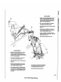
S h o u l d It become necessary to adjust the throttle
l i n k a g e , r e f e r to F i g u r e IS for the complete i n s t r u c tions.
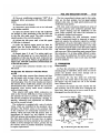
BSD CARBURETOR
14-15
BOWL VENT
VALVE
UNLOADER
TANG
FAST IDLE
SPEED ADJUSTING
SCREW
FAST IDLE
CAM
ACCELERATOR
PUMP ROD
VENT HOLE
THROTTLE LEVER
CURB IDLE
SPEED ADJUSTING
SCREW
CHOKE VALVE
AIR HORN
CHOKE LEVER
CHOKE OPERATING
LINK
CARBURETOR
IDENTIFICATION
TAG
FAST IDLE
SPEED ADJUSTING
SCREW
M A I N BODY
FAST IDLE
CONNECTOR ROD
.
DISTRIBUTOR VACUUM
ADVANCE TUBE FITTING
CURB IDLE
SPEED ADJUSTING
SCREW
CHOKE V A C U U M
DIAPHRAGM
CLOSED CRANKCASE
VENT TUBE FITTING
VACUUM
DIAPHRAGM
HOSE
THROTTLE BODY
ELEVATOR LEGS
(SET OF 4 )
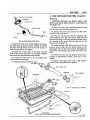
64 x 328
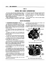
Fig. 1—Carburetor Assembly (BBD-3685IS)
14-16
BBD CARBURETOR
PART 2
MODEL BBD 3685S CARBURETORS
Dirt, dust, water and gummy deposits are some of
the main causes for poor carburetor operation. Proper
cleaning, however, and installation of new parts,
where required, will return the carburetor to its
originally designed performance.
When overhauling the carburetor, several items
of importance should be observed to assure a good
job. All parts (except the diaphragm assembly) should
be carefully cleaned in a suitable solvent and inspected for damage and wear. Replace questionable
parts with new ones.
Use air pressure only, to clear the various orifices
and passages.
SERVICE PROCEDURES
1 CARBURETOR DISASSEMBLY ( F i g . 1 )
(1) Insert three Tool T109-287S and one Tool T109288S elevating legs through the carburetor throttle
body stud holes. (These tools are used to protect the
throttle valves from damage and to provide a suitable
base for working.)
(2) Remove the hairpin clip and disengage the fast
idle connector rod from the throttle and fast idle
levers.
(10) Lift out the float fulcrum pin retainer, and
lift out the floats and fulcrum pin.
(11) Remove the step-up piston and retaining screw
and slide the step-up piston and rods out of well,
as shown in Figure 2. lift out the step-up piston
STEP-UP PISTON
STEP-UP RODS
STEP-UP PISTON
SPRING
(3) Remove the hairpin clip and disengage the
accelerator pump rod from the throttle lever and the
pump rocker arm.
MAIN
METERING
JETS
(4) Remove the vacuum hose between the carburetor throttle body fitting and the vacuum diaphragm.
(5) Remove the clip from the choke operating link
and disengage the link from the diaphragm plunger
and the choke lever. (Refer to Fig. 1.)
-RETAINING SCREW
(6) Remove the vacuum diaphragm and bracket assembly and place to one side, to be cleaned as a
special item. A liquid cleaner other than mineral
spirits, may damage the diaphragm material.
(7) Remove the air horn retaining screws and lift
air horn straight up and away from the main body.
Discard the gasket.
60x102
Fig. %— Removing the Step-up Piston
SPECIAL
TOOL
(8) Disengage the accelerator pump plunger from
the accelerator pump arm by pushing up on the bottom of the plunger and sliding the plunger shaft off
the hook. Slide the plunger out of the air horn and
remove the compression spring and seat.
If the old plunger can be used again or if a new
plunger is to be installed, place the plunger in a jar
of clean gasoline or kerosene to prevent the leather
from drying out.
(9) Remove the fuel inlet needle valve, seat and
gasket from the main body.
MAIN
METERING
JETS
64 x 329
Fig. 3—Removing the Main Metering Jet
BBD CARBURETOR
GASKETS
VENTURI
CLUSTER
ACCELERATOR PUMP
DISCHARGE HOLES
if
=5
ACCELERATOR PUMP
DISCHARGE PASSAGE
VENTURI CLUSTER
SCREWS
14-17
provide an additional hole for the removal of dirt.
Compressed air can be used to remove loose dirt but
should not be connected to the vacuum inlet fitting.
IMPORTANT: If the commercial solvent or
cleaner recommends the use of water as a rinse, it
should be " H O T . " After rinsing, all trace of water
must be blown from the passages with air pressure. It
is further advisable to rinse all parts in clean kerosene
or gasoline to be certain no trace of moisture remains.
Never clean jets with a wire, drill or other mechanical means, because the orifices may become enlarged,
making the mixture too rich for proper performance.
64x330
Fjg. 4—Removing the Venturi Cluster
spring. Remove the step-up piston gasket from the
bottom of the well.
(12) Remove the main metering jets and gaskets,
as shown in Figure 3.
(13) Remove the venturi cluster screws, then lift
the venturi cluster and gaskets up and away from
the main body, as shown in Figure 4. Discard the gaskets. Do not remove the idle orifice tubes or the main
vent tubes from the cluster. They can be cleaned in a
solvent arid dried with compressed air.
(14) Invert the carburetor and drop out the accelerator pump discharge check ball.
(15) Remove the idle mixture adjusting screws and
springs from the throttle body.
(16) Remove the screws that attach the throttle
body to the main body. Separate the bodies and discard the gasket.
The carburetor now has been disassembled into
three sub-assemblies, the air horn, main body and
throttle body and the components of each disassembled as far as necessary for cleaning and inspection.
It is usually not advisable to remove the throttle
shaft or valves from the throttle body, unless wear
or damage necessitates the installation of new parts.
3 . INSPECTION A N D REASSEMBLY
Throttle
Body
(1) Inspect the throttle shaft and throttle body for
excessive wear. If either or both are worn to the
point where the carburetor operation will be affected,
replace as required.
During manufacture, the location of the idle transfer port and the spark advance control ports to the
throttle valve, is carefully established for one particular assembly (Fig. 5).
If a new shaft should be installed in an old, worn
throttle body, it would be very unlikely that the
original relationship of the ports to the valves would
be obtained. Changing the relationship of the valves
to the ports would adversely affect normal car operation between the speeds of 15 and 30 miles per hour.
If it has been determined, however, that a new shaft
or valves is to be installed, adhere to the following
instructions.
(2) Mark the position of the throttle valves in the
bores. Be sure the idle speed screw is backed off.
(3) Remove the screws that hold the throttle valves
to the shaft and slide the valves out of the bores.
I D L
7oRTS
S F E R
SPARK ADVANCE
PORT
2. C L E A N I N G CARBURETOR
The recommended solvent for gum deposits is denatured alcohol which is easily obtainable. There are
other commercial solvents, however, which may be
used with satisfactory results.
The choke diaphragm can be damaged by solvents.
Avoid placing the diaphragm assembly in A N Y liquid.
Clean the external surfaces with a clean cloth or soft
wire brush. Shake dirt or other foreign material from
the stem side of the diaphragm. Depressing the diaphragm plunger (stem) to the retracted position, will
VENT HOLE
VENT HOLE
64x331
Fig. 5 — P o r t s in R e l a t i o n to Throttle V a l v e s
14-18
BBD CARBURETOR
CAUTION: These screws are staked on the opposite side and care should he used at removal so as
not to break off in the shaft. Remove the staked end
of the screws with a file.
(4) Slide the throttle shaft and lever out of the
body.
(5) Install new throttle shaft and lever.
(6) Install throttle valves in their respective bores
(with the valve number toward the manifold). Install
new screws but do not tighten. Hold the valves in
place, with the fingers pressing on the high sides of
the valves. Tap the valves lightly with a screwdriver
to seat in the throttle bores. Tighten the screws
securely and stake by squeezing with pliers.
(7) Install the idle mixture screws and springs in
the throttle body. (The tapered portion must be
straight and smooth. If the tapered portion is grooved
or ridged, new idle mixture screws should be installed
to insure having correct idle mixture control.) DO
NOT U S E A SCREWDRIVER. Turn the screws lightly
against their seats with the fingers. Back off one full
turn for approximate adjustment.
Main Body
(1) Invert the main body and place a new gasket
in position and place the throttle body on the main
body and align. Install screws and tighten securely.
(2) Install the accelerator pump discharge check
ball in the discharge passage and check the accelerator pump system; fuel inlet and discharge check
balls as follows:
(3) Pour clean gasoline into the carburetor bowl,
approximately Vi inch deep. Remove the pump
plunger from the jar of gasoline, flex the leather
several times, then slide down into the pump cylinder.
Raise the plunger and press lightly on the plunger
shaft to expel all air from the pump passage.
(4) Using a small clean brass rod, hold the discharge check ball down firmly on its seat. Again raise
the plunger and press downward. No fuel should be
emitted from either the intake or discharge passage,
as shown in Figure 6.
If any fuel does emit from either passage it indicates the presence of dirt or a damaged check ball
seat. Check the passage again and repeat test. If
leakage is still evident, install a new check ball.
The fuel inlet check ball is located at the bottom
of the plunger well.
(5) Install new gaskets on the venturi cluster, and
install in position in the main body (Fig. 4). Install
the idle bleed screws and tighten securely. Test pump
discharge by pressing pump plunger down. Two fine
streams of fuel should be forced from the cluster.
If either stream is restricted or diverted, remove
cluster and reclean. After test, pour the fuel from
the bowl and remove pump plunger.
(6) Install the main metering jets and gaskets.
Tighten securely (Fig. 3).
(7) Before installing the step-up piston, be sure the
step-up rods are able to move freely, each side of
the vertical position, as shown in Figure 7. The step-up
rods must be straight and smooth.
(8) Slide the step-up piston gasket down into position in the piston well, then install the step-up piston
springs, step-up piston and rods. Carefully guide the
step-up rods into the main metering jets (Fig. 2).
Install the retaining screw and tighten securely. Check
piston for free operation in the well.
A step-up piston stuck in the Up position will cause
a rich mixture at part throttle, whereas a piston stuck
in the Down position will cause a lean mixture at
wide open throttle and poor acceleration.
STEP-UP R O D S MUST M O V E FREELY
Fig. 6—Testing the Accelerator Pump Intake a n d
Discharge Check Balls
Fig. 7 — S t e p Up Rods Free Play
BBD CARBURETOR
14-19
NOTE: After being compressed, the rubber tip
is very slow to recover its original shape* It is very
important that the float lip be perpendicular to the
needle or slanted not more than 10 degrees away
from the needle when the float height is correct.
Air Horn
(1) Test the freeness of the choke mechanism in
the air horn. The choke shaft must float free to
operate correctly. If the choke shaft sticks in the
bearings, or appears to be gummed from deposits in
the air horn, a thorough cleaning will be required.
(2) Remove the accelerator pump plunger from
the gasoline, slide the compression spring and spring
seat over the shaft. Install the assembly in the air
horn and engage with the accelerator pump arm.
Fig. 8—Measuring the Float Setting
Measuring
the Float Setting
(Off the Vehicle)
The carburetors are equipped with a rubber-tipped
fuel inlet needle. The rubber tip is flexible enough to
make a good seal on the needle seat, and to give increased resistance to flooding.
The use of the rubber-tipped needle requires a
new procedure in adjusting the float setting. Care
should be taken to perform this operation accurately
in order to secure the best performance and fuel
economy.
(1) To correctly set the float height when the carburetor is being overhauled, install the floats with
the fulcrum pin and pin retainer in the main body.
(2) Install the rubber-tipped needle, seat and gasket in the body and tighten securely.
(3) Invert the main body so that the weight of the
float only is forcing the needle against the seat. Hold
finger against the retainer to fully seat the fulcrum
pin.
(4) Using Tool T109-282, or a "T" scale, measure
the float, as shown in Figure 8. There should be VA
inch from the surface of the fuel bowl to the crown
of each float at the center.
If an adjustment is necessary, hold the floats on
the bottom of the bowl and bend the float lip toward
or away from the needle. Recheck the VA inch setting
again and repeat the lip bending operation as required.
CAUTION: When bending the float lip, da not
allow the lip to push against the needle as the rubber
tip can be compressed sufficiently to cause a false
setting which will affect correct level of fuel in the
bowl.
(3) Place a new gasket on the main body, and install
the air horn. Install attaching screws and tighten
securely. (When installing air horn, be sure the
leather on the plunger does not wrinkle or fold back.)
(4) Engage the accelerator pump rod with the pump
rocker arm and install loose end in the center hole
of throttle lever. Install hairpin clip to secure.
(5) Engage the fast idle connector rod in the fast
idle lever and throttle lever. Install hairpin clip to
secure.
Installing the Vacuum
Diaphragm
(1) Install the diaphragm assembly on the air horn
and tighten the attaching screws securely.
(2) Install the choke operating link in position between the diaphragm plunger (stem) and the choke
lever. Install the clip to secure.
(3) Inspect the vacuum diaphragm fitting and remove any dirt or foreign material which could plug
the passage. Inspect the rubber hose for cracks, before placing it on the correct fitting. (Refer to Fig. 1.)
Do not connect the vacuum hose to the diaphragm
fitting until after the vacuum kick adjustment has
been made. (See Carburetor Adjustments.)
4 . CARBURETOR ADJUSTMENTS
It is very important that the following adjustments
are made on a reconditioned carburetor and in the
sequence listed:
Accelerator Pump
(1) Back off the idle speed adjusting screw. Open
the choke valve so that the fast idle cam allows the
throttle valves to be completely seated in the bores.
Be sure that the pump connector rod is installed in
the center hole of the throttle lever.
(2) Close the throttle valves tightly. Measure the
14-20
BBD CARBURETOR
Fig. 9—Measuring the Accelerator Pump Travel
distance between the top of the air horn and the end
of plunger shaft, as shown in Figure 9. This measurement should be 1" + or — £ inch.
x
4
(3) To adjust the pump setting, bend the pump connector rod, using Tool T109-213, at the lower angle
of rod, until the correct travel has been obtained.
Fast Idle Speed
Adjustment
and Cam
Position
Fig. 11—Measuring the Choke Vacuum Kick Setting
(2) An adjustment will be necessary if a slight drag
is not obtained as the drill or gauge is being removed.
(3) If an adjustment is necessary, bend the stop on
the choke shaft, using Tool T109-22 until the correct
valve opening has been obtained. (Refer to Fig. 10.)
Vacuum Kick Adjustment—(This test can be made
On or Off the vehicle.)
The fast idle engine speed adjustment should be
made on the engine, as described in the Fast Idle
Speed Adjustment (On the engine) paragraph of this
group, however, the Fast Idle Cam Position Adjustment can be made on the bench, as follows:
(1) With the fast idle speed adjusting screw contacting the lowest step on the fast idle cam, as shown
in Figure 10, move the choke valve toward the closed
position with light pressure. Insert a *% inch drill
or gauge between the choke valve and the wall of the
air horn.
4
To make the vacuum kick adjustment, the vacuum
diaphragm must be energized (either a distributor
testing machine with a vacuum source, or vacuum
supplied by another vehicle). To make this adjustment, proceed as follows:
(1) With the engine Not running, open the throttle
valves far enough to allow the choke valve to be
moved to the closed position.
(2) Disconnect the vacuum hose from the diaphragm and connect the hose from the Vacuum
supply, as shown in Figure 11. (A minimum of 10
inches of mercury (HG) will be required.)
1
(3) Insert a % inch drill or gauge between the
choke valve and the wall of the air horn (Refer to
Fig. 11). Apply a slight closing pressure to the choke
shaft to hold the drill or gauge in position.
4
(4) An adjustment will be necessary if a slight drag
is not obtained as the drill or gauge is being removed.
The adjustment of this opening will require the
removal of the choke operating link.
C A U T I O N : DAMAGE T O T H E DIAPHRAGM A N D
T H E C H O K E L E V E R S L O T C A N R E S U L T , IF T H E
L I N K IS NOT R E M O V E D F O R THE BENDING OPERATION.
Fig. 10—-Fast Idle Cam Position Adjustment
(5) Remove the clip and disengage the choke
operating link from the diaphragm stem (plunger),
then disengage the link from the choke lever. (The
BBD CARBURETOR
14-21
Fig. 12—Choke Operating Link Measurements
Fig. 14—Measuring the Choke Unloader Setting
best bending results will be obtained by using a vise
and a pair of pliers.)
(6) Bend the choke operating link to provide the
correct choke valve opening.
some clearance should exist between the choke
operating link and the choke lever slot, in both the
open and closed choke valve positions, as shown in
Figure 13.
C A U T I O N : A c o r r e c t i o n in t h e length of the l i n k
of .010 i n c h , w i l l r e s u l t in a c h a n g e of .010 inch in t h e
choke valve opening.
N O T E : T h i s c l e a r a n c e i s n e c e s s a r y to a l l o w t h e
c h o k e v a l v e to close f o r starting a s w e l l a s f u l l y open
position a f t e r the e n g i n e reaches t h e n o r m a l operating
temperature.
As an example, if the choke valve opening is .010
inch in error, the correction in the link length would
be .010 inch.
A 2" micrometer will be helpful in establishing the
original length of the link, as shown in Figure 12,
before completing the adjustment.
(7) Install the choke operating link and retest the
choke valve opening, using a gauge or drill. (Refer
to Fig. 11.)
Reinstall the vacuum hose to the diaphragm and
make the following test:
(8) With no vacuum applied to the diaphragm,
Fig. 13—Choke Operating Link Clearances
If a clearance does not exist in both of these
positions, a retest of the operating link adjustment
should be made.
N O T E : F r e e m o v e m e n t of t h e c h o k e v a l v e between
the closed a n d open positions is v e r y n e c e s s a r y .
This free movement should also exist between the
kick and the open choke valve positions with the
engine running. If binding does exist, the choke
operating link has been improperly bent and should
be corrected.
Fig. IS—Bending the Unloader Tang
14-22
BBD CARBURETOR
Choke Unloader (Wide O p e n JOcJcJ
(1) Hold the throttle valves in the wide open position. Insert Tool T109-31 or a W drill shank) between
the upper edge of the choke valve and the inner wall
of the air horn, as shown in Figure 14.
(2) With a finger lightly pressing against the valve,
a slight drag should be felt as the gauge is being
withdrawn. If an adjustment is necessary, bend the
tang on the fast idle lever, ^
as
shown in Figure 15, until the correct clearance has
been obtained.
Bowl Vent Volve
Adjustment
(1) With the throttle valves at curb idle, there
should be y inch clearance between the bowl vent
valve and the air horn, when measured (at the center
of the vent valve and the seat) with a drill shank.
(2) If an adjustment is necessary, bend the short
tang on the vent valve operating lever, using Tool
T109-22 until the correct opening has been obtained.
16
Idle S p e e d Adjustment
(Curb
Idlei
To make the idle speed adjustment, the engine
must be thoroughly warmed up. A more reliable idle
adjustment can usually be obtained if the car has
been driven a minimum of five miles. For best results,
it is recommended that a tachometer be used in this
adjustment.
On vehicles equipped with automatic transmission,
loosen the nut in the sliding link of the carburetor
to bellcrank rod so that the stop in the transmission
will not interfere with the free movement of the carburetor throttle lever.
(1) To make the idle speed adjustment, turn the
idle speed screw in or out to obtain 500 rpm. (6n
cars with air conditioning, set the idle speed at 500
rpm.) With air conditioning ON be sure the choke
valve is fully open and that the fast idle adjusting
screw is not contacting the fast idle cam.
(2) Turn each idle mixture screw in or out to obtain
the highest rpm. While making the adjustment, carefully watch the tachometer and notice that the speed
can be decreased by turning the screws in either
direction from the setting that gave the highest rpm
reading.
(3) Readjust to 500 rpm with the idle speed screw.
(With air conditioning ON).
(4) Turn each idle mixture adjusting screw in the
clockwise direction (leaner) until there is a slight
drop in rpm. Turn each screw out, counterclockwise
(richer) just enough to regain the lost rpm.
This procedure will assure that the idle has been
set to the leanest mixture possible for smooth idle.
This setting is very important.
Since the correct speed was originally set, using
the speed screw, the speed obtained after finding
the leanest smooth idle will probably be too fast.
(5) Readjust the speed screw to obtain correct idle
speed. Repeat steps 2 and 4 above if necessary.
After the proper idle speed has been obtained,
move the sliding link to the rear against the stop
and tighten the nut securely.
5. M E A S U R I N G THE FLOAT SETTING OR
FUEL LEVEL ( O n the V e h i c l e )
To measure the float setting with the carburetor
mounted on the engine, proceed as follows:
(1) Remove the hairpin clip and disengage the
accelerator pump rod from the throttle lever and
the pump rocker arm. Disconnect the automatic
choke rod by unsnapping clip.
(2) Remove the air horn attaching screws and lift
the air horn straight up and away from the main
body. Remove the gasket.
(3) Set the float fulcrum pin by pressing a finger
against the fulcrum pin retainer.
There should be enough fuel in the bowl to raise
the floats so that the lip bears firmly against the
needle. Additional fuel may be admitted by slightly
depressing the float. If the fuel pressure in the line
is insufficient to force the additional fuel into the
bowl, add the necessary fuel from a clean container.
WARNING: Since the manifolds may be hot, it
is dangerous to spill fuel onto these surfaces. Take
the necessary precautions to avoid spillage.
(4) With only the pressure from the buoyant float
holding the lip against the inlet needle, check the
float setting, using Tool T109-282, or a " T " scale.
There should be VA inch from the surface of the
bowl (gasket removed) to the crown of the floats at
the center.
If an adjustment is necessary, hold the floats on
the bottom of the bowl, then bend the float lip toward
or away from the needle. Recheck the VA inch setting
again, then repeat the lip bending operation as required.
CAUTION: When bending the float lip, do not
allow the lip to push against the needle as the rubber
tip can be compressed sufficiently to cause a false
setting which will affect correct level of fuel in the
bowl.
NOTE: After being compressed, the rubber tip
is very slow to recover its original shape. It is very
important that the float lip be perpendicular to the
needle or slanted not more than 10 degrees away
from the needle when the float is set correctly.
(5) After the float has been correctly set, reassemble the air horn.
BBD CARBURETOR
14-23
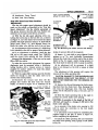
Fig. 17—Closed Crankcase Vent System
Fig. 16—Fast Idle Speed Adjustment (On the Engine)
Fast Idle Speed Adjustment
(On the
Engine)
To set the fast idle speed on the engine, connect a
tachometer to the vehicle, then set the curb idle
speed and proceed as follows:
(1) With the engine running and the transmission
in the neutral position, open the throttle slightly.
(2) Close the choke valve about 20 degrees then
allow the throttle to close. Return the choke valve to
the open position.
(3) The fast idle adjusting screw should be contacting the lowest step on the fast idle cam, as shown
in Figure 16.
(4) With the engine warmed-up to the normal
operating temperature, turn the fast idle adjusting
screw in or out to secure 700 rpm. Reposition the
earn and throttle after each adjustment.
6 . AUTOMATIC C H O K E — W E L L TYPE
To function properly, it is important that all parts
be clean and move freely. Other than an occasional
cleaning, the choke requires no servicing. It is very
important, however, that the choke control unit work
freely in the well and at the choke shaft.
Move the choke rod up and down to check for free
movement on the pivot. If the unit binds, a new
choke unit should be installed. THE W E L L TYPE
CHOKE UNIT is serviced as an assembly. Do not
attempt to repair or change the index setting.
When installing the well type choke unit, be certain that the coil housing does not contact the sides
of the well in the intake manifold. Any contact at
this point will affect choke operation.
Do not lubricate any parts of the choke or the control unit. This causes an accumulation of dirt which
will result in binding of the choke mechanism.
9. CLOSED C R A N K C A S E VENT SYSTEM
The closed crankcase ventilator valve is located
in the crankcase vent tube cap and is connected to
the carburetor throttle body with a rubber tube. (See
Fig. 17.)
The function of the valve is to regulate the flow
of unburned hydrocarbons from the crankcase and
return them to the intake manifold. From here they
enter the combustion chamber and then exit with
the exhaust system as completely burned exhaust
products. For servicing procedures of this system,
refer to "Engine," Group 9.
10.
THROTTLE -LINKAGE
To adjust the throttle linkage refer to Figure 18
for the complete instructions.
4*
i
WITH MANUAL TRANSMISSION
1.
ASSEMBLE ACCELERATOR SHAFT ASSEMBLY AND PEDAL ASSEMBLY TO
BODY, WITH A 3/16" DIAMETER R O D ® A P P R O X I M A T E L Y TO" LONG
IN T H E HOLES PROVIDED IN THE ACCELERATOR SHAFT BRACKET AND
L E V E R , ADJUST THE PEDAL R O D ® L E N G T H TO PROVIDE A P E D A L
ANGLE O F 113° TO 115°INSTALL P E D A L R O D . ®
1
A P P L Y A THIN FILM OF MS 3608 LUBRICANT TO THE ACCELERATOR
S H A F T S ? ) WHERE IT TURNS IN T H E FIREWALL BRACKET.
3.
m
ASSEMBLE CARBURETOR ROD PARTS BUT DO NOT TIGHTEN ADJUSTMENT
LOCK NUT. ®
"DISCONNECT C H O K E @ A T CARBURETOR OR BLOCK CHOKE V A L V E IN
F U L L OPEN POSITION. OPEN THROTTLE SLIGHTLY TO R E L E A S E FAST
I D L E CAM, THEN RETURN CARBURETOR TO CURB IDLE.
WITH T H E 3/16" DIAMETER BY 10" LONG R O D ® t N P L A C E IN THE
ACCELERATOR SHAFT BRACKET AND L E V E R ASSEMBLY, TIGHTEN CARBURETOR ROD ADJUSTMENT LOCK N U T . ®
CONNECT CHOKE R O D ® O R REMOVE BLOCKING FIXTURE.
WITH AUTOMATIC TRANSMISSION
ASSEMBLE ACCELERATOR SHAFT ASSEMBLY AND PEDAL ASSEMBLY TO
BODY. WITH A 3/16" DIAMETER R O D ® A P P R O X I M A T E L Y 10" LONG
IN T H E HOLES PROVIDED IN THE ACCELERATOR SHAFT BRACKET AND
L E V E R , ADJUST T H E P E D A L R O D ® L E N G T H TO PROVIDE A PEDAL ANGLE
OF 113°TO 115°INSTALL PEDAL R O D . ®
1
APPLY A THIN FILM O F MS 3608 LUBRICANT TO THE ACCELERATOR
S H A F T ® W H E R E IT TURNS IN THE FIREWALL BRACKET.
3.
ASSEMBLE CARBURETOR ROD PARTS BUT DO NOT TIGHTEN ADJUSTMENT
LOCK N U T . ®
4.
DISCONNECT C H O K E ® ) A T CARBURETOR OR BLOCK CHOKE V A L V E IN
F U L L OPEN POSITION. OPEN THROTTLE SLIGHTLY TO R E L E A S E FAST
I D L E CAM, THEN RETURN CARBURETOR TO CURB IDLE.
5.
WITH T H E TRANSMISSION ROD ASSEMBLY AND TRANSMISSION T H R O T T L E
L E V E R IN P L A C E , MOVE THE TRANSMISSION THROTTLE L E V E R ® FORWARD AGAINST T H E STOP AND TIGHTEN TRANSMISSION ROD ADJUSTMENT
LOCK N U T . ® R E M O V E 3/16" DIAMETER R O D ® F R O M ACCELERATOR
SHAFT BRACKET.
6.
MOVE REAR PORTION OF CARBURETOR ROD ASSEMBLY © R E A R W A R D
UNTIL TRANSMISSION T H R O T T L E L E V E R ® STOP IS CONTACTED.
TIGHTEN CARBURETOR ROD ADJUSTMENT LOCK N U T . ®
7.
CONNECT CHOKE R O D @ O R REMOVE BLOCKING FIXTURE.
63x367
Fig. 18—Throttle Linkage Adjustments
i
•p"
•r-
"2
>O
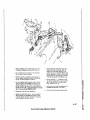
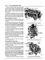
AFB CARBURETOR
14-25
>TEP UP PISTON COVER PLATE
ACCELERATOR
PUMP PLUNGER STEM
CHOKE OPERATING LINK
FUEL INLET FITTING
CHOKE VACUUM DIAPHRAGM
PLUNGER (STEM)
J
3
l f e ^ ^
\ \ ^ f ^ ^ ^ ^ y .
" ' ^
<#^f
/-V
«r
'
-
SECONDARY THROTTLE
OPERATING LEVER
THROTTLE A N D M A I N BODY
PRIMARY THROTTLE
SHAFT ARM (OUTER)
CHOKE VACUUM DIAPHRAGM BRACKET
PRIMARY THROTTLE
SHAFT D O G
VACUUM DIAPHRAGM HOSE
CHOKE LEVER
CHOKE OPERATING LINK
STEP UP PISTON
COVER PLATE
CHOKE VALVE
Y
ACCELERATOR PUMP ARM
\
CHOKE VACUUM
DIAPHRAGM/>"*^~'
Sy
/
HUT
x
>~.
AIRHORN
3
FAST IDLE
CONNECTOR ROD
DIAPHRAGM
VACUUM HOSE
FAST IDLE C A M
CURB IDLE SPEED
ADJUSTING SCREW
• M i
DISTRIBUTOR
VACUUM ADVANCE
TUBE FITTING
• THROTTLE LEVER
IDLE MIXTURE
ADJUSTING SCREWS
FAST IDLE SPEED
ADJUSTING SCREW
CLOSED
CRANKCASE VENT
TUBE FITTING
ELEVATING LEGS
(SET OF 4)
ACCELERATOR PUMP
CONNECTOR ROD
Fig. 1—Carburetor Assembly (AFB Series)
64x340
14-26
AFB CARBURETOR
PART 3
AFB CARBURETORS
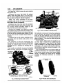
The AFB (aluminum four barrel) carburetor contains many features, some of which are the location
for the step-up rods and pistons. The step-up rods,
pistons and springs are accessible for service without
removing the air horn, or the carburetor from the
engine.
The venturi assemblies (primary and secondary)
are replaceable and contain many of the calibration
points for both the high and low speed system. One
fuel bowl feeds both the primary and secondary
nozzles on the right side while the other fuel bowl
takes care of the primary and secondary nozzles on
the left side. This provides improved performance in
cornering, quick stops and acceleration.
All the major castings of the carburetor are aluminum, with the throttle body cast integral with the
main body. This allows an overall height reduction
in the carburetor. The section containing the accelerator pump is termed the primary side of the carburetor. The rear section is the secondary.
The five conventional systems are two float systems, two low speed systems (primary side only),
two high speed systems, one accelerator pump system and one automatic choke control system.
SERVICE PROCEDURES
1. SERVICING THE CARBURETOR
Dirt, dust, water and gummy deposits are some of
the main causes for poor carburetor operation. However, proper cleaning and the installation of new
parts, where required, will return the carburetor to
its originally designed performance.
When overhauling the AFB carburetor, several
items of importance should be observed to assure a
good job.
The carburetor should be carefully disassembled
and all parts (except the choke diaphragm assembly)
should be cleaned in a suitable solvent and inspected
for wear or damage.
Air pressure only should be used to clean the
various orifices and channels. Replace questionable
parts with new ones.
(4) Remove the vacuum hose between the carburetor body and the vacuum diaphragm.
(5) Remove the clip from the choke operating link
and disengage the link from the diaphragm plunger
(stem) and the choke lever. (Refer to Fig. 1.)
(6) Remove the vacuum diaphragm and bracket assembly and place to one side to be cleaned as a
separate item. A liquid cleaner may damage the diaphragm material.
(7) Remove the screws attaching the step-up piston
and rod cover plates.
NOTE: Hold cover down with a finger to prevent
the piston and rods from flying out.
STEP UP PISTON
2 , DISASSEMBLING THE CARBURETOR
(Fig* 1 )
(1) Place the carburetor assembly on repair stand
Tool C-3400 or T-109-287S elevating legs.
(2) Remove the hairpin clip that attaches the fast
idle connector rod to the choke lever. Disengage rod
from lever, then swing rod at an arc until it can be
disengaged from the fast idle cam.
(3) Remove the retainer and spring that holds the
throttle connector rod in the center hole of the accelerator pump arm. Remove the hairpin clip that attaches the lower end of rod in the primary throttle
shaft lever. Disengage rod from arm and lever, then
remove from carburetor.
STEP UP
PISTON ROD
STEP UP
PISTON SPRING
SCREW
COVER PLATE
SPRING
Fig. 2—Hemoving Step-up Pistons and Rods
AFB CARBURETOR
14-27
(8) Lift off the plates and slide the step-up pistons
and rods out of the air horn, as shown in Figure 2.
Remove the step-up piston springs.
(9) Remove the ten screws that attach the air horn
to the main body (1 screw in hole in air horn). lift
air horn straight up and away from the main body.
NOTE: When removing air horn, use care so as
not to bend or damage the floats.
(10) Remove the accelerator pump plunger lower
spring from the pump cylinder.
Disassembling
the Air Horn
Place the air horn in an inverted position on the
bench (to protect the floats).
(1) Using a suitable tool, remove the float fulcrum
pins (left and right) and lift the floats up and out of
bosses on air horn.
NOTE: It is suggested that the float on the pump
side be marked so that the floats can be re-installed
in their respective positions.
(2) Remove the two needle valves from their respective seats, after .marking the one on the pump
side for identification. Using a wide blade screw
driver, remove the needle valve seats. Be sure each
needle valve is returned to its original seat at reassembly.
(3) Remove the hairpin clip that holds the accelerator pump connector link in the pump arm and
plunger ihaft. Disengage link from pump arm and
shaft. Slide the accelerator pump pluhger and spring
out of the air horn. Remove the air horn to main
body gasket and discard.
(4) Place the accelerator pump plunger in a jar of
clean gasoline or kerosene,, to prevent the leather
from drying out.
,
ATTACHING
SCREWS
Fig. 4—Removing .Main Metering Jets
(5) Remove the fuel inlet fitting and filter screen
from the air horn.
(6) Test the freeness of the choke mechanism in
the air horn. The choke shaft must float free to
operate correctly. If the choke shaft sticks in the
bearings, or appears to be gummed from deposits in
the air horn, a thorough cleaning will be required.
Main Body
Disassembly
(1) Remove the screws that attach the accelerator
pump jet housing to the main body. Lift out the jet
housing and gasket, as shown in Figure 3. Discard
the gasket. Invert the main bpdy and drop out the
discharge check needle from the discharge passage.
(2) Using Tool T109-58 remove the main metering
jets (secondary side), as shown in Figure 4.
NOTE: The primary and secondary main metering jets are not interchangeable. It is very important
that these gets be installed in their respective locations in the main body at reassembly.
I
63x50i|A
Fig. 3—Removing Accelerator Pump Jet Housing
Fig. 5*—Removing Primary, Venturi
14-28
AFB CARBURETOR
(3) Using Tool T-109-58, remove the main metering
jets (primary side).
(4) Remove the screws that attach the primary
venturi (choke and pump side) to the main body,
lift the venturi straight up and away from the main
body, as shown in Figure 5. Discard the gaskets.
IDLE DISCHARGE
PORTS
PRIMARY THROTTLE
JVALVES
NOTE: The venturi assemblies are not interchangeable, side for side and must be re-installed in
their original location at reassembly.
(5) Remove the screws that attach the secondary
venturi (choke and pump side) to the main body. lift
the secondary venturi assemblies straight up and
away from the body, as shown in Figure 6.
(6) Using Tool T-109-59, screw driver bit, remove
the accelerator pump intake check ball assembly. (The
check ball assembly is located at the front of the bowl
at the base of the accelerator pump cylinder. Be sure
that the check ball is thoroughly cleaned before installation.
(7) Remove the two idle mixture adjusting screws
and springs from the throttle body portion of the
mlin casting.
The carburetor now has been disassembled into
two units, the air horn and main and throttle body
casting. The component parts of each have been disassembled as far as necessary for cleaning and inspection.
It is usually not advisable to remove the throttle
shafts or valves, unless wear or damage necessitates
SECONDARY
VENTURI
(PUMP SIDC
SECONDARY
VENTURI
(CHOKE SIDE)
GASKET
IDLE TRANSFER PORTS
Fig. 7_Porfrs in Relation to Throttle Valves
the installation of new parts. During the manufacture
of the carburetor, the location of the idle transfer
ports arid the idle discharge ports to the valve is
papfully established for one particular assembly, as
shown in Figure 7. The valves are milled to give the
proper port relation.
If new throttle shafts should be installed in an
old, worn body, it would be very unlikely that the
original relationship of these ports to the valves
would be obtained. A very slight change in the port
relationship to the valves would adversely affect normal carburetor operation, between the speeds of 15
and 30 miles per hour.
It is recommended that if the throttle shafts are
excessively worn, that a new carburetor be installed.
If the throttle valves, however, have become nicked,
burred or damaged, new valves may be installed,
providing the following instructions are carefully
followed:
y
NOZZLE BLEEDER TUBE
PRIMARY VENTURI
63x505A
• SECONDARY VALVE
(BRASS)
SECONDARY VENTURI
M A I N BLEED TUBE
NOZZLE BLEEDER TUBE
IDLE TUBE
D O N O T REMOVE TUBES FROM VENTURI
63x504A
Fig. 6—Removing Secondary Venturi
PRIMARY VALVE
(ALUMINUM)
„
WXV46A
O
Fig. 8—Throttle Valve Identification
A
A
A
AFB CARBURETOR
NOTE: The screws that attach the throttle valves
are staked on the opposite side and care should be
used in removal so as not to break the screws in the
throttle shaft. Remove the staked portion of the
screws with a file.
Remove the screws that attach the primary throttle
valves to the throttle shaft and slide valve (or valves)
out of the bores.
Remove the screws that attach the secondary throttle valves to the throttle shaft and slide valve (or
valves) out of the bores.
The primary valves and secondary valves are not
interchangeable and should be kept separate in order
that each may be returned to its respective bore.
(See Fig. 8.)
3 . CLEANING THE CARBURETOR PARTS
The recommended solvent for gum deposits is denatured alcohol. There are other commercial solvents,
however, which may be used with satisfactory results.
The choke diaphragm can be damaged by solvents.
Avoid placing the diaphragm assembly in any liquid.
Clean the external surfaces with a clean cloth or soft
wire brush. Shake dirt or other foreign material from
the stem side of the diaphragm. Depressing the diaphragm stem to the retracted position, will provide an
additional hole for the removal of dirt. Compressed
air can be used to remove loose dirt, but should not
be connected to the vacuum inlet fitting.
IMPORTANT: If the commercial solvent or
cleaner recommends the use of a water rinse, it
should be "HOT/' After rinsing, all trace of water
must be blown from the passages with air pressure. It
is further advisable to rinse all parts in clean kerosene
or gasoline to be certain no trace of moisture remains.
Never clean jets with a wire, drill, or other mechanical
means, because the orifices may become enlarged,
making the mixture too rich for proper performance.
3 . INSPECTION A N D REASSEMBLY
Main and Throttle Body
Casting
(1) Slide the primary throttle valve (or valves) into
their respective bores, install new screws, but do not
tighten. Be sure the idle speed adjusting screw is
backed out. Hold the valves in place with fingers
(fingers pressing on the high side of the valves).
(2) Tap the valves lightly with a screw driver to
seat in the bores. Holding the valves in this position,
tighten the screws securely. Stake screws by squeezing
with pliers.
(3) Install the two idle mixture adjusting screws
and springs in the throttle body portion of the casting.
14-29
The tapered portion must be smooth and straight.
If the tapered portion is grooved or ridged, a new
idle mixture adjusting screw should be installed to
insure having correct idle mixture control.
NOTE:
Do not use a screw driver.
The adjustment should be made with the fingers.
Turn the idle mixture adjusting screws lightly against
their seats and back off one full turn for an approximate adjustment.
(4) Place the new secondary venturi gaskets in
position (bleed hole in top, toward the center of the
carburetor), install the secondary venturi (pump and
choke side) by lowering straight down on the gaskets.
Install the attaching screws and tighten securely.
NOTE: Be sure all the metering holes and vent
tubes are clean, in both the primary and secondary
venturi.
(5) Place new primary venturi gaskets in position,
then install the primary venturi (pump and choke side)
by lowering straight down on the gaskets. (See Fig.
5.) Install attaching screws and tighten securely.
(6) Install the primary and secondary main metering jets, using Tool T109-58. (See Fig. 4.) Tighten
jets securely.
(7) Install the accelerator pump intake check ball
assembly in position in the carburetor bowl. Tighten
securely, using Tool T109-59.
Accelerator Pump Test
(1) Pour clean gasoline into the carburetor bowl
(approximately V% inch deep). Remove the accelerator
pump plunger from the jar of gasoline. Flex the
leather several times, then slide it on the pump
cylinder.
(2) Install the accelerator pump discharge check
needle in the discharge passage. Raise the pump
plunger and press lightly on the plunger shaft to expel air from the pump passages. Using a small clean
brass rod, hold the discharge check needle firmly on
its seat. Again raise the plunger and press downward.
No fuel should be emitted from either the intake or
discharge passage.
(3) If fuel does emit from the intake passage, disassemble the intake check ball and reclean the passage. Fuel leakage at the discharge check needle indicates the presence of dirt or a damaged check
needle. Clean again and then install a new check
needle. Retest for leakage.
(4) If either the intake check ball or discharge
check needle leaks after above test and service fix,
attempt to reseat as follows:
14-30
AFB CARBURETOR
Intake Cheek Ball
Remove the accelerator pump check ball assembly
and install a new check ball assembly.
Discharge Cheek
Needle
(1) With the discharge check needle installed, insert a piece of drill rod down on the needle. lightly
tap the drill rod with a hammer to form a new seat.
Remove and discard old needle and install a new
one. Retest as described previously. If the service
fix does not correct the condition, a new carburetor
must be installed.
(2) Install the accelerator pump discharge check
needle, jet housing and gasket. Install housing and
attaching screws. Tighten screws securely.
(3) Press down on the accelerator pump plunger
shaft and as the plunger is being depressed, a clear
straight stream should emit from each jet. If the
streams are identical (if either one is diverted or
restricted) a new accelerator pump jet housing should
be installed. After test, pour the gasoline from the
carburetor bowl and remove pump plunger.
Air Horn
Assembly
(1) Slide the fuel inlet screen into the fuel line
fitting, then install fitting in air horn. Tighten securely.
(2) Inspect to see if the leather on the accelerator
pump plunger is hard, cracked or worn. If any sign
of wear or deterioration is evident, install a new
plunger assembly.
(3) When reassembling, make sure the large diameter of the pivot screw enters the hole in the pump
arm and that the shoulder of the screw has not
pinched the pump arm.
(4) Place a new air horn to main body gasket in
position on the air horn and install the float needle
valve seats. (Be sure each needle seat and needle is
reinstalled in its original position.)
The carburetors are equipped with synthetic rubber-tipped fuel inlet needle. The rubber tip is flexible
enough to make a good seal on the needle seat, and
to give increased resistance to flooding.
Fig. 9—Measuring the Float Alignment
NOTE: Be sure the marked float is installed on
the pump side of the air horn.
(6) After the floats have been installed, test the
float alignment, level and drop settings as follows:
Float Alignment
Setting
(1) Sight down the side of each float shell to determine if the side of the float is parallel to the outer
edge of the air horn casting, as shown in Figure 9.
(2) If the sides of the float are not in alignment
with the edge of casting, bend the float lever by
applying pressure to the end of the float shell with
the fingers while supporting the float lever with the
thumb.
NOTE: To avoid damage to the float, apply only
enough pressure to bend the float lever.
(3) The arms of the float lever should be parallel
to the inner surfaces of the lugs or the casting.
Float Level
Setting
(1) With the air horn inverted, the air horn gasket
GASKET IN PLACE
NOTE: The use of the rubber-tipped needles require that care be used when making float adjustments. Avoid applying any pressure on the floats
which might compress the tip of the fuel inlet needles.
The rubber tip can be compressed sufficiently to cause
a false setting which will affect correct level of fuel
in the bowl.
(5) Slide the right and left floats into position in
the air horn and install the float fulcrum pins.
Fig. 10—Measuring the Float Height
FLOAT
AFB CARBURETOR
14-31
Fig. 12—Step-up Piston, Rod and Jet
Fig. 11—Measuring the Float Drop
in place and the float needle seated, slide the float
gauge Tool T109-106 (% ") between the top of the
float (at outer end) and the air horn gasket, as
shown in Figure 10.
2
(2) Measure the other float in the same manner.
If an adjustment is necessary, bend the float arm
using Tool T109-22, until correct clearance has been
obtained. After bending arm, recheck the float alignment.
Float Drop Smiting
(1) Holding the air horn in an upright position,
measure the distance from the top of the floats (outer
end) to the air horn gasket, as shown in Figure 11.
This measurement should be % inch. If an adjustment
is necessary, bend the stop tabs on the float levers
until the correct drop setting has been obtained. Bend
the tab towards the needle seat to lessen the drop, or
away from the seat to increase the drop.
(2) After the floats have been inspected and adjusted, continue to assemble the carburetor as follows:
(3) Place the accelerator pump plunger lower
spring in the pump cylinder, then lower the air horn
carefully down on the main body.
CAUTION: Be sure the fuel baffles on the air
horn, slide down in front (bowl side) of the float
chamber baffles, or the air horn will not index correctly with the main body and can cause the floats to
hang up. Be sure the leather on the plunger does not
curl or wrinkle. Accelerator pump operation will
be affected if this precaution is not observed.
(4) Install the (10) air horn attaching screws and
tighten securely. (The two long screws should be installed in the holes that are located at the air cleaner
mounting surface. The 1 inch screw at the front and
the IV2 inch at the rear.)
The change from the low speed, best fuel economy,
road load mixtures to the richer wide open throttle
pull mixtures is accomplished in two steps. This has
made it possible to secure best low speed fuel economy
without sacrificing performance in the intermediate
speed range. To do this, there is a new step-up piston
and spring assembly, new metering rods with three
diameters, and new style primary metering jets, as
shown in Figure 12.
(5) Slide the step-up piston springs into the piston
cylinders, followed by the step-up pistons and step-up
rods. Install the cover plates and attaching screws
while holding the step-up pistons down in position.
Tighten screws securely.
(6) Slide the choke piston into its cylinder in the
air horn, guiding the link into the slot in the choke
valve lever. Align hole, then install attaching cotter
pin. Place a new welch plug over the cylinder opening
and secure by rapping with a hammer. (Be sure the
sealing surface is clean.) Check the fit of the choke
valve in air horn. The valve should be evenly spaced
on all sides. Loosen screws and reposition, if necessary.
(7) Engage the throttle connector rod with- the
primary throttle shaft lever and install hairpin clip.
Install the other end of the connector rod in the pump
arm and secure with clevis clip.
(8) Engage the lower end of the fast idle connector
rod with the fast idle cam, then swing in an arc to
lock in cam. Slide other end of rod into the choke
shaft lever and secure with hairpin clip.
Installing the Vacuum
Diaphragm
(1) Install the vacuum diaphragm assembly on the
main body and tighten the attaching screws securely.
(2) Install the choke operating link in position between the diaphragm plunger (stem) and the choke
lever. Install the clip to secure.
14-32
AFB CARBURETOR
(3) Inspect the vacuum diaphragm fitting and remove any dirt or foreign material which could clog
the passage. Inspect the rubber hose for cracks, before
placing it on the correct throttle body fitting. (Refer
to Fig. 1.)
*
r
G A U G E OR DRILL
LIGHT C L O S I N G
PRESSURE AGAINST VALVE
CHOKE
OPERATING LINK
v
Do not connect the vacuum hose to the diaphragm
fitting until after the vacuum Mck adjustment has
been made. (See Carburetor Adjustments.)
4 . CARBURETOR ADJUSTMENTS
The adjustments are made with the carburetor on
the bench for ease of working, and should be made
in the following order:
Fast Idle Speed and Cam Position
Adjustment
The fast idle engine speed adjustment should be
made on the engine, as described in the Fast Idle
Speed Adjustment (On the engine) paragraph of this
group, however, the Fast Idle Cam Position Adjustment can be made on the bench.
(1) Open the throttle valves far enough to allow the
fast idle speed adjusting screw to clear the fast idle
cam.
(2) Insert a % inch drill or gauge between the
choke valve and the air horn wall, as shown in Figure
13.
(3) Close the throttle valves until the fast idle speed
adjusting screw contacts the fast idle cam.
(4) Adjust the fast idle connector rod, using Tool
T109-213 by bending at the angle until the fast idle
speed adjusting screw lightly contacts the middle step
on the fast idle cam, but slides onto the bottom step
of the cam. The fast idle speed adjusting screw must
DIAPHRAGM
STEM
VACUUM
CHOKE
TUBE FITTING
MINIMUM
10 INCHES
O F VACUUM
O N DIAPHRAGM
REQUIRED
64x348
Fig. 14—Measuring the Choke Vacuum Kick Setting
touch or ride against the shoulder of the middle step
on the cam.
(This special procedure is required because the fast
idle speed cam is spring loaded to follow the choke
valve.)
Vacuum Kick Adjustment—(This test can be made
ON or Off the vehicle.)
2
DRILL OR G A U G E —
LIGHT CLOSING PRESSURE
AGAINST CHOKE VALVE
BEND FAST IDLE CONNECTOR ROD
AT THIS ANGLE
(3) Insert a Vs inch drill or gauge between the
choke valve and the wall of the air horn. (Refer to
Fig. 14.) Apply a slight closing pressure to the choke
shaft to hold the drill or gauge in position.
(4) An adjustment will be necessary if a slight drag
is not obtained as the drill or gauge is being removed.
The adjustment of this opening will require the
removal of the choke operating link.
FAST
IDLE ADJUSTING
SCREW O N
LOWEST STEP O F
CAM AND RIDING
AGAINST SHOULDER
O F MIDDLE STEP
CAUTION: DAMAGE TO THE DIAPHRAGM AND
THE CHOICE LEVER SLOT CAN RESULT, IF THE
LINK IS NOT REMOVED FOR THE BENDING OPERATION.
CAM
SCREW
64x346
Fig. 13—Fast Idle Cam Position Adjustment
To make the vacuum kick adjustment, the vacuum
diaphragm must be energized (either a distributor
testing machine with a vacuum source, or vacuum
supplied by another vehicle.) To make this adjustment, proceed as follows:
(1) With the engine Not running, open the throttle
valves far enough to allow the choke valve to be
moved to the closed position.
(2) Disconnect the vacuum hose from the diaphragm and connect the hose from the vacuum supply, as shown in Figure 14. (A minimum of 10 inches
of mercury (HG) will be required.)
(5) Remove the clip and disengage the choke operating link from the choke lever, then disengage the
link from the diaphragm stem. (The best bending
AFB CARBURETOR
14-33
64x349
Fig. 15—Choke Operating Link Measurement
results will be obtained by using a vise arid a pair of
pliers.)
. . «.
(6) Bend the choke operating link to provide the
correct choke valve opening.
CAUTION: A correction in the length of the
link of .015 inch, will result in a change of .010 inch
in the choke valve opening.
As an example, if the choke valve opening is .010
inch in error, the correction in the link length would
be .015.
A 2" micrometer will be helpful in establishing the
original length of the link, as shown in Figure 15,
before completing the adjustment.
(7) Install the choke operating link and retest the
choke valve opening, using a drill or gauge. (Refer
to Fig. 14.)
Reinstall the vacuum hose to the diaphragm and
make the following test:
(8) With no vacuum applied to the diaphragm, some
clearance should exist between the choke operating
link and the choke lever slot, in both the open and
closed choke valve positions, as shown in Figure 16.
Fig. 16—Choke Operating Link Clearances
Fig. 17—Testing Choke Unloader (Wide Open Kick)
NOTE: This clearance is necessary to allow the
choke valve to close for starting as well as fully open
after the engine reaches the normal operating temperature.
If a clearance does not exist in both of tliese positions^-av-gej&st of the operating link adjustment should
be made."
NOTE: Free movement of the choke valve between
the closed and open positions is very necessary.
This free movement should also exist between the
kick and the open choke valve positions with the
engine running. If binding does exist, the choke
operating link has been improperly bent and should
be corrected.
C h o i c e Unloader
Adjustment
(1) With the throttle valves in the wide open position, it should be possible to insert Tool T109-80
(% inch) gauge between the upper edge of the choke
valve and the inner wall of the air horn, as shown in
Figure 17.
(2) If an adjustment is necessary, bend the unloader lip on the throttle shaft lever, using Tool
T109-41, until correct opening has been obtained.
Accelerator
Pump
Adjustment
(1) Move the choke valve to wide open position,
to release the fast idle cam. Back off the idle speed
adjusting screw, (curb idle) until the throttle valves
are seated in the bores.
(2) Measure the distance from the top of the air
horn to the top of the plunger shaft, using a "T"
scale as shown in Figure 18. This distance should be
%e inch.
(3) If an adjustment is necessary, bend the throttle
connector rod at the lower angle, using Tool T-109213, until correct travel has been obtained.
14-34
AFB CARBURETOR
ACCELERATOR PUMP
PLUNGER STEM
SECONDARY THROTTLE VALVES
SHOULD JUST START TO OPEN
BEND ROD AT THIS ANGLE
PRIMARY
THROTTLE
VALVES
ly
^NOTCHOF
LOCK-OUT
DOG
CURB IDLE
SPEED SCREW
6ACKED O F F
THROTTLE
FULLY
CLOSED
BEND THROTTLE
CONNECTOR ROD
AT THIS ANGLE
64x353
F j . i & — T e s t i n g the Accelerator Pump Adjustment
g
S e c o n d a r y Throttle Lever
Adjustment
(1) To measure the secondary throttle lever adjustment, block the choke valve in the wide open
position and invert the carburetor.
(2) Slowly open the primary throttle valves until
it is possible to measure % inch between the lower
edge of the primary valve and the bore (opposite idle
port) as;shown in Figure 19. At this measurement,
the secondary valves should just start to open.
(3) If an adjustment is necessary, bend the secondary throttle operating rod at the angle, using
Tool T109-213, until correct adjustment has been
obtained.
(4) With the primary and secondary throttle valves
in the tightly closed position, it should be possible
to insert Tool T109-29 {.020 inch) wire gauge, between
the positive closing shoes on the secondary throttle
levers, as shown in Figure 20.
(5) If an adjustment is necessary, bend the shoe on
the secondary throttle lever, using Tool T109-22, until
correct clearance has been obtained.
2
4
Secondary
Throttle Lock-out
Adjustment
(1) Open the throttle valves slightly, then manually open and close the choke valve. The tang on the
secondary throttle lever should freely engage in the
notch of the lock-out dog. (Refer to Fig. 19.)
(2) If an adjustment is necessary, bend the tang
on the secondary throttle lever, until engagement
has been made. Use Tool T109-22 for this operation.
(3) After adjustments have been made, reinstall
carburetor on engine, using a new gasket.
(4) It is suggested that the carburetor bowl be
filled with clean gasoline. This will help prevent dirt
that is trapped in the fuel system from being dis-
TANG O N
SECONDARY
THROTTLE LEVER
CHOKE VALVE
WIDE OPEN
SLOWLY OPEN
THROTTLE VALVES
64x355
Fig. 19—Testing the Secondary Throttle Adjustment
lodged by the free flow of fuel, as the carburetor is
primed.
Idle Speed Adjustment
(Curb I d l e l
To make the idle speed adjustment, the engine must
be thoroughly warmed up. A much more reliable idle
adjustment can usually be obtained if the car has
been driven a minimum of five miles. For the best
results, it is recommended that a tachometer be uped
in this adjustment. (Before making the idle speed
adjustment, observe the following precautions:)
On cars equipped with the automatic transmission
loosen the nut in the sliding link of the carburetor
to bellcrank rod so that the stop in the transmission
will not interfere with the free movement of the
carburetor throttle lever.
(1) To make the idle speed adjustment, turn the
idle speed screw in or out to obtain 500 rpm. (On
cars with air conditioning, set the idle speed at 500
SECONDARY
SHOE-
PRIMARY SHOE
(BEND TO ADJUST)
WIRE G A U G E
64x356
Fig. 2 0 — M e a s u r i n g C l e a r a n c e Between Closing
Shoes
f
AFB CARBURETOR
14-35
Fig. 21—Fast Idle Speed Adjustment (On the Engine!
Fig. 22—Closed Crankcase Vent System
rpm.) Be sure the choke valve is fully open and that
the fast idle adjusting screw is not contacting the fast
idle cam.
(2) Turn each idle mixture screw to obtain the
highest rpm. While making the adjustment, carefully
watch the tachometer and notice that the speed can
be decreased by turning the screws in either direction
from the setting that gave the highest rpm. reading.
allow the throttle to close. Return the choke valve to
the wide open position.
(3) Readjust to 500 rpm. with the idle speed screw.
(Air conditioning ON).
(4) Turn each idle mixture adjusting screw in the
clockwise direction (leaner) until there is a slight drop
in rpm. Turn each screw out, counter-clockwise
(richer) just enough to regain the lost rpm.
This procedure will assure that the idle has been
set to the leanest possible mixture for smooth idle.
This setting is very Important.
NOTE; Since the correct speed was originally
set using the speed screw, the speed obtained after
finding the leanest smooth idle setting will probably
be too fast.
(5) Readjust the speed screw to obtain correct idle
speed. Repeat steps 2 and 4 above if necessary.
After the proper idle speed has been obtained,
move the sliding link to the rear, against the stop,
and tighten the nut securely.
Fctsf idle Speed Adjustment
( On ffie
Engine)
To set the fast idle speed on the engine, connect a
tachometer to the vehicle, then set the curb idle speed
and proceed as follows:
(1) With the engine running and the transmission
in the neutral position, open the throttle slightly.
(2) Close the choke valve about 20 degrees, then
(3) The fast idle speed adjusting screw should be
contacting the lowest step on the fast idle cam, as
shown in Figure 21.
(4) With the engine warmed-up to the normal
operating temperature, turn the fast idle speed adjusting screw in or out to secure 700 rpm. Reposition
the cam and throttle after every fast idle speed screw
adjustment.
5 . AUTOMATIC C H O K E { W e l l T y p e )
To function properly, it is important that all parts
be clean and move freely. Other than the occasional
cleaning, the automatic choke control requires no
servicing. It is very important, however, that the
choke control unit moves freely at the thermostatic
coil spring housing and at the choke shaft. Move the
choke rod up and down to check for free movement
of the coil housing on the pivot. If unit binds, a new
unit should be installed. The Well Type Choke Control
Unit is serviced only as a complete unit. Do not
attempt to repair.
Do not lubricate any parts of the choke or control
unit since this causes dirt accumulation which would
result in binding of the choke mechanism.
Do not attempt to change the calibration setting.
(Refer to specifications.) This is pre-determined and
should it be changed, improper action would result.
Clean all choke parts using a suitable solvent and
then blow dry with compressed air. Examine all choke
parts for wear or damage. Worn or damaged parts
must be replaced with new in order to insure proper
choke operation.
When installing the well type choke unit, make
certain that the coil housing does not contact the
14-36
AFB CARBURETOR
sides of the wall in the intake manifold. Any contact
at this point will affect operation.
6. CLOSED C R A N K C A S E VENT SYSTEM
The closed crankcase ventilator valve is located in
the crankcase vent tube cap and is connected to the
carburetor throttle body via a rubber tube. (See Fig.
22.) The function of the valve is to regulate the flow
of unburned hydrocarbons from the crankcase and
return them to the intake manifold. From here they
enter the combustion chamber and then exit via the
exhaust system as completely burned exhaust products.
For servicing procedures of this system, refer to
the "Engine section" Group 9.
7. THROTTLE LINKAGE
To adjust the throttle linkage, refer to Figure 23
for the complete instructions.
1.
2.
3.
4.
5.
6.
ASSEMBLE TRANSMISSION CONTROL LINKAGE PARTS IN PLACE BUT DO
NOT ASSEMBLE TRANSMISSION ROD BALL SOCKET @ TO BALL END.
APPLY A THIN FILM OF MS 3701 LUBRICANT TO THE ACCELERATOR
SHAFT 0 WHERE IT TURNS IN THE BRACKET.
7.
DISCONNECT CHOKE (?) AT CARBURETOR OR BLOCK CHOKE VALVE IN
FULL OPEN POSITION, OPEN THROTTLE SLIGHTLY TO RELEASE FAST
8.
IDLE CAM, THEN RETURN CARBURETOR TO CURB IDLE,
HOLD THE TRANSMISSION LEVER © FORWARD AGAINST ITS STOP AND
ADJUST THE LENGTH OF THE TRANSMISSION ROD BY MEANS OF THE
THREADED ADJUSTMENT @ AT THE UPPER END. THE BALL SOCKET
MUST LINE UP DIRECTLY WITH THE BALL END WITHOUT EXERTING ANY
9.
FORWARD FORCE ON THE ROD. THE BALL SOCKET MUST BE AT THE SAME
HEIGHT AS THE BALL END WHEN CHECKING ROD LENGTH.
10.
LENGTHEN ROD BY ONE TURN OF THE ADJUSTMENT. ®
ASSEMBLE REMAINDER OF THE LINKAGE PARTS IN PLACE.
WITH THE CABLE CLAMP NUT (J) LOOSE, ADJUST THE
POSITION OF THE CABLE HOUSING FERRULE ® IN THE
CLAMP SO THAT ALL SLACK IS REMOVED FROM THE CABLE
WITH THE CARBURETOR AT CURB IDLE. TO REMOVE SLACK
FROM THE CABLE, MOVE THE FERRULE ® IN THE CLAMP
IN THE DIRECTION AWAY FROM THE CARBURETOR LEVER.
BACK OFF FERRULE (J) 1/2" . THIS PROVIDES 1/2" FREE
PLAY BETWEEN THE REAR SURFACE OF THE ACCELERATOR
BRKT. AND THE FRONT EDGE OF ACCELERATOR SHAFT
LEVER. TIGHTEN CLAMP NUT ©
7®
o
ROUTE CABLE SO THAT IT DOES NOT INTERFERE WITH THE
TRANSMISSION ROD THROUGHOUT ITS FULL TRAVEL.
CONNECT CHOKE ROD © OR REMOVE BLOCKING FIXTURE.
m
z
ASSEMBLE BALL SOCKET @ TO BALL END. WHEN THE CARBURETOR
THROTTLE IS OPENED, THE TRANSMISSION SHOULD BEGIN ITS TRAVEL
AT THE SAME TIME WITH NO VERTICAL MOVEMENT OF THE LEVER OR
VERTICAL MOVEMENT OF THE ROD IN THE LEVER.
7s
>
64 x 422
Fig. 23—Throttle Linkage Adjustments (Imperial)
!
4*
i
CO
N
14-38
FUEL AND INDUCTION SYSTEM
PART 4
FIRE POWER 3 9 0 FUEL AND INDUCTION SYSTEM
The Chrysler Fire Power 390 engine, as shown in
Figure 1, is equipped with twin air cleaners, twin
AFB carburetors, hand type chokes and two aluminum
manifolds, containing eight sweeping passages (four in
each manifold), all of which ekiploys a new method
of fuel induction.
: .
SERVICE PROCEDURES
1. INTAKE MANIFOLDS
Removal
(Fig. 21
(1) Drain the cooling system.
(2) Remove the carburetor air cleaners.
(3) Disconnect the fuel line between the fuel pump
and the left hand carburetor.
(10) Remove the air conditioning cqnipressor and
brackets, (if so equipped). Refer to Air Conditioning
Section.
vS-?%
8
(11) Remove the eight attaching bolts that hold the
left fender shield access plate to fender shield, then
slide plate out of the engine compartment.
(4) Disconnect the fuel line between the left and
right hand carburetor. Disconnect the choke control.
(12) Remove the two bolts that attach the left hand
by-pass pipe to the lower chamber, v ^ ^ ;
(5) Disconnect the vacuum line between the right
hand carburetor and the distributor.
(13) Remove the two bolts that attach the left hand
exhaust manifold elbow to the lower chamber. Discard
the gaskets.
(6) Remove the high tension coil wire.
(7) Disconnect the throttle linkage at both carburetors and the bell crank, to the accelerator shaft.
(8) Loosen the clamps that attach the equalizer tube
couplings to the manifolds, and to the equalizer tube.
Slide either coupling inward on the tube far enough
to clear the manifold tube opening. Lift the equalizer
tube, couplings and clamps up and away from engine.
(9) Disconnect the power steering hoses (if so
equipped) at the pump and secure against the fire
wall.
(14) Remove the four bolts that attach the intake
manifold to the right bank cylinder head. Remove the
exhaust passage crossover cover.
(15) Lift the intake manifold and carburetor from
the engine as an assembly.
(16) Remove the nuts that attach the carburetor to
the intake manifold. Remove the carburetor.
(17) Remove the eight attaching bolts that hold the
right fender shield access plate to the fender shield,
then slide plate out of engine compartment.
(18) Remove the two bolts that attach the right
hand exhaust by-pass pipe to the lower chamber.
(19) Remove the two bolts that attach the right
hand exhaust manifold elbow to the lower chamber.
Discard the gaskets.
(20) Remove the four bolts that attach the intake
manifold to the left bank cylinder head. Remove the
exhaust passage crossover cover.
(21) Lift the manifold and carburetor from the
engine as an assembly.
Fig. 1<—Fire Power Manifold
(22) Remove the nuts that attach the carburetor to
the intake manifold, then disconnect the automatic
choke rod from the lever. Remove the carburetor.
FUEL AND INDUCTION SYSTEM
Installation
When installing the intake manifolds be sure and
use new gaskets and be sure all mating surfaces are
smooth and clean.
To install the left hand intake manifold, refer to
Figure 2, then proceed as follows:
(1) Place the carburetor in position on the mounting pad of the intake manifold and engage the choke
control. Install the carburetor mounting nuts and
tighten.
(2) Place the intake manifold assembly in position
on the right hand bank cylinder head. Place the exhaust crossover passage cover over the passage, then
install the manifold attaching bolts finger tight.
(3) Slide a new gasket between the left hand exhaust manifold elbow and the lower chamber of the
intake manifold. Install attaching bolts finger tight.
(4) Slide a new gasket between the left hand exhaust by-pass pipe and the manifold lower chamber.
Install the attaching bolts and tighten to 10 footpounds. Tighten the elbow attaching bolts to 10
foot-pounds and the intake manifolds bolts to 50 footpounds.
14-39
(5) Slide the left hand fender shield access plate
into position against fender shield. Install bolts and
tighten.
If both intake manifolds were removed, continue to
install the right hand manifold as follows:
(6) Place the carburetor in position on the mounting pad of the intake manifold and connect the choke
control. Install the carburetor mounting nuts and
tighten.
(7) Place the intake manifold assembly in position
on the left hand bank cylinder head. Place the exhaust
crossover passage cover over the passage, then install
the manifold attaching bolts finger tight.
(8) Slide a new gasket between the right hand exhaust manifold elbow and the lower chamber of the
intake manifold. Install attaching bolts finger tight.
(9) Slide a new gasket between the right hand exhaust by-pass pipe and the lower chamber. Install
attaching bolts and tighten to 10 foot-pounds. Tighten
the elbow attaching bolts to 10 foot-pounds and the
intake manifold bolts to 50 foot-pounds.
(10) Slide the right hand fender shield access plate
into position against fender shield. Install bolts and
tighten.
CLAMP
W I N G NUT
AIR CLEANER STUD
CARBURETOR
ASSEMBLY
INTAKE
MANIFOLD-RIGHT
INTAKE MANIFOLD-LEFT
EXHAUST CROSSOVER
COVER
GASKET REINFORCEMENT
GASKET
-GASKET
GASKET
SEALER AS REQUIRED
HEAT INLET ELBOW
Fig. 2—Fire Power Manifold (Disassembled)
60x166
14-40
FUEL AND INDUCTION SYSTEM
(11) Place the air conditioning compressor arid
brackets in position (if so equipped) and install attaching bolts. Tighten securely. (Refer to the Air Conditioning Group 24 for method of recharging the system.)
1
far enough to firmly engage the manifold. Tighten
clamps securely.
(14) Reconnect the throttle linkage at both carburetor and bell-crank to accelerator shaft.
(15) Reinstall the high tension coil wire.
(12) Reconnect the Power Steering hoses to the
pump (if so equipped). (Refer to Power Steering Group
19 for method of bleeding air out of the system.)
(16) Reconnect the vacuum line between the carburetor and distributor.
(13) Slide the equalizer tube, clamps and couplings
over the manifold tubes. Slide either coupling outward
(17) Reconnect the fuel line between the left and
right hand carburetors.
- RIGHT BANK CARBURETOR ROD
CHOKE CABLE
/ADJUSTING LINK
IT) LOCKING BOLT AND NUT
.ACCELERATOR SHAFT TO THROTTLE SHAFT LEVER ROD
/ADJUSTING LINK
TOP VIEW
(t)
^
LOCKING BOLT
AND NUT
/ L O C K I N G NUT ( ? )
f
ADJUSTING LINK
ACCELERATOR SHAFT AND BRACKET
/BELLCRANK T O TRANSMISSION ROD
- TRANSMISSION THROTTLE CONTROL LEVER
-KICK D O W N
LEFT BANK
CARBURETOR ROD
POSITION
• WIDE OPEN THROTTLE POSITION
-51° 15'
IDLE POSITION
SPRING (2)
n
LOCKING NUT
ACCELERATOR PEDAL TO SHAFT ROD
INSTRUMENT PANEL
INSTRUMENT
PANEL
ACCELERATOR SHAFT T O THROTTLE
SHAFT LEVER ROD
ACCELERATOR SHAFT BRACKET
ACCELERATOR PEDAL T O SHAFT ROD
ACCELERATOR PEDAL
ACCELERATOR SHAFT T O BELLCRANK ROD
(T) LOCKING NUT
SIDE VIEW
ADJUSTING LINK
63x569
Fig. 3-—Throttle Linkage (Schematic)
FUEL AND INDUCTION SYSTEM
(18) Reconnect the fuel line between the fuel pump
and the left hand carburetor.
(19) Reinstall the right and left carburetor air
cleaners.
(20) Refill the cooling system to required capacity.
(Refer to specifications.)
After the intake manifolds have been installed it is
very important that the next procedure of setting the
throttle linkage be done in order to obtain peak engine performance.
2 . SETTING THE THROTTLE L I N K A G E
As mentioned previously, setting the throttle linkage is a very important step. Various conditions affecting car performance can be encountered, such as
loss of performance, no wide open throttle response,
delayed shifting of the transmission, no kickdown, delayed up shifts and etc.
Setting the throttle linkage is divided into three
parts, namely: Positioning the accelerator shaft, positioning the accelerator pedal, setting the bellcrank
and synchronizing each carburetor. It is very important that the throttle linkage be set in this order.
Positioning the Accelerator
Shaft
To position the accelerator shaft, (if equipped with
automatic transmission) refer to Figure 3 then proceed as follows:
(1) Loosen the adjusting nuts "A" and "B" (accelerator shaft to transmission rod and accelerator shaft to
throttle shaft lever rod).
(2) Insert a piece of % inch welding rod, 10 inches
long into the accelerator shaft bracket and through
hole in lever.
6
(3) Now move the transmission throttle lever forward until it stops. Tighten the locknut "A" securely.
This positions the accelerator shaft.
Positioning the Accelerator
Pedal
(1) Unsnap the accelerator pedal from shaft rod.
(2) Turn the threaded end of rod either in or out
until a measurement of 114 degrees is obtained between the floor of car and the flat face of the accelerator pedal.
(3) This measurement can be made with a spirit
protractor.
(4) After correct measurement has been obtained,
reconnect rod. Remove pin from accelerator shaft
bracket.
14-41
Setting the Bellcrank
(1) Loosen locking nuts "C" and "D" (left and right
bank carburetor rods).
(2) Pivot the ballcrank until a % inch piece of
welding rod 3 inches long can be inserted through the
bellcrank hole and down into the locating hole in the
intake manifold.
6
(3) Test each carburetor to be sure the choke valves
are open; that the fast idle cams are released and that
the throttle valves are closed.
(4) Tighten locking nuts "C" and "D" securely.
Remove pin from bellcrank.
(5) Push rearward on the accelerator shaft to throttle shaft lever rod adjusting link, until stop is obtained. Tighten locking nut securely.
Idle Speed and Mixture
Adjustment
Connect a tachometer and warm-up the engine to
normal operating temperature. Be sure the choke
is fully off and that the engine is at curb idle, (transmission in Neutral). Proceed as follows:
(1) Turn the idle mixture screws from 1 to 2 turns
open.
(2) Set the idle bypass air screws 2 turns open and
adjust the idle speed to 700 rpm. or if equipped with
air conditioning, 500 rpm. with the compressor ON.
The idle bypass air screw is located at the front of
each carburetor body flange, between the two idle
mixture screws. Adjust the idle mixture screws on
each carburetor for maximum rpm. Repeat on each
carburetor.
Before attaching the rod at each carburetor, check
the transmission to throttle linkage adjustments, so
that the idle position is not disturbed.
NOTE: Accurate carburetor synchronization or
balance is exteremely important and when performed
should be rechecked and rebalanced in the outside
ambient temperature after a five mile or more road
test. This readjustment will prevent rough engine
idle performance and possible engine stalling when
the vehicle is returned to the owner.
Fast Idle Adjustment
(On
Vehicle)
When making fast idle adjustment on the vehicle,
each AFB carburetor should be adjusted individually.
(1) The engine should be at normal operating temperature and have a curb idle speed of 700 rpm. or
if equipped with air conditioning, 500 rpm. with the
compressor ON.
14-42
FUEL AND INDUCTION SYSTEM
CHOKE VALVE
FUEL INLET FITTING \
CHOKE CABLE
CLAMP
fc
}
I 1 M
IDLE MIXTURE
ADJUSTING SCREWS
STEP-UP PISTON
COVER PLATE ( 2 )
%
1 J - .«
AIR HORN
FAST IDLE ROD
&
FAST IDLE C A M
CARBURETOR
IDENTIFICATION
STAMPED O N BOSS
ELEVATING LEGS (SET OF 4 )
IDLE BY-PASS
ADJUSTING SCREW
MAIN AND
THROTTLE BODY
THROTTLE LEVER
STEP-UP PISTON
COVER PLATE ( 2 )
ACCELERATOR PUMP
CONNECTOR LINK
CHOKE LEVER
ACCELERATOR
PUMP SHAFT
ACCELERATOR
PUMP ARM
CHOKE CABLE
BRACKET
ACCELERATOR PUMP
CONNECTOR ROD
SECONDARY THROTTLE
OPERATING LEVER
VACUUM ADVANCE
FITTING OPENING
CARBURETOR IDENTIFICATION
STAMPED O N BOSS
PRIMARY THROTTLE
SHAFT ARM (OUTER)
63x607
Fig. 4—Carburetor Assembly (AFB-3505S)
FUEL AND INDUCTION SYSTEM
(2) Turn air conditioning compressor "OFF" (if so
equipped) before proceeding with following adjustments.
(3) Remove each air cleaner.
(4) Disconnect each throttle rod at the belcrank
on the intake manifold.
(5) Open the throttle valves of the left carburetor
far enough to allow positioning of the fast idle cam
to the fast idle index mark. The right carburetor
should remain at the curb idle position.
(6) Adjust fast idle screw until a fast idle speed
of 1400 rpm. is obtained.
(7) After the desired engine speed has been obtained, open the throttle slightly to allow the fast
idle cam to return to the open choke (or off fast idle)
position.
(8) Repeat steps 5, 6 and 7 in setting right carburetor fast idle speed as it is very important at the
completion of this step (8), that each carburetor has
identical fast idle speeds. There is no specification for
engine rpm. with both carburetors simultaneously set
at the fast idle position.
(9) Connect both carburetor throttle rods to the
bejl crank.
Carburetor
Air Cleaner'—Do
Not Wash
or Oil
Every 5,000 miles, remove filter element and blow
out dirt gently with air hose. Direct air from inside
out, and keep nozzle 1 inch away from element to
avoid damaging. Clean the metal housing and replace
the element. Every 15,000 miles, install a new factory
recommended filter element. Service the unit more
frequently when driving under severe conditions,
such as in dusty areas.
Twin 4-barrel AFB series 3505S carburetors are
used on the Chrysler 300K (Fig. 4). These carburetors
are basically the same as previous AFB carburetors.
The service procedures for disassembly, cleaning, inspection, reassembly and adjustments are different
and will be covered in detail.
The carburetor is equipped with a pair of velocity
valves, which are controlled by the secondary valve
operation. The throttle valves in the secondary half
of the carburetor are mechanically connected to the
primary valves and open with the primary after an
approximate 60 degree lag; and continue to open
until both primary and secondary throttle valves reach
the wide open position at the same time. As engine
speed increases, the forces exerted by the velocity of
intake air down through the venturi, permits the off
set velocity valves to position themselves according
to engine requirements.
14-43
The four conventional systems used in this carburetor are two float systems, two low speed systems
(primary side only), two high speed systems and the
accelerator pump system.
,
Dirt, dust, water and gummy deposits are some of
the main causes for poor carburetor operation., However, proper cleaning and the installation of new
parts, where required, will return the carburetor to
its originally designed performance.
When overhauling the AFB carburetor, several
items of importance should be observed to assure a
good job; namely, the carburetor should be carefully
disassembled. All parts thoroughly cleaned in a suitable solvent, then inspected for damage or wear. Only
air pressure should be used to clear the various orifices
and channels. Questionable parts should be replaced
with new ones. (When inspecting parts removed from
the carburetor, it is at times rather difficult to determine if they are satisfactory for further service. It is
recommended, therefore, that in such case, that NEW
parts be installed.)
3 . CARBURETOR
Disassembly
(1) Place the carburetor on repair stand C-3400 or
elevating legs (4) T109-287S. (These tools are used to
protect the throttle valves from damage and to
provide a suitable base for working.)
(2) Remove the clip that holds the accelerator
pump rod in the center hole in the pump arm, and
the hairpin clip that holds the rod in the throttle
lever. Remove the rod.
(3) Remove the hairpin clip that attaches the fast
idle connector rod to the choke lever. Disengage rod
from lever, then swing rod at an arc until it can be
disengaged from the fast idle cam.
Fig. 5—'Removing the Step Up Pistons
14-44
FUEL AND INDUCTION SYSTEM
(4) Remove the step-up piston cover plate screws
and plates. (Hold a finger over plate when removing
screws to prevent the piston and metering rods from
flying out.) Remove the step-up pistons and metering
rods, as shown in Figure 5. Remove the step-up
piston springs.
(5) Remove the choke cable bracket, then remove
the ten air horn attaching screws (1 screw recessed).
Then lift the air horn straight up and away from main
body. Be careful not to bend or damage the floats.
Remove the pump plunger spring from the pump well.
Disassembling
the Air Horn
Place the air horn in an inverted position on the
bench (mainly to protect the floats), then disassemble
as follows:
(f) Remove the float fulcrum pins, then remove
each float. (Before removing floats, it is suggested
that "the float on the pump side be marked so that
the floats can be installed in their original locations.)
63x610
Fig. ©—Removing the Pump Jet Housing
(2) Remove the two needle valves, after marking
the pump side for identification.
(3) Using a wide blade screwdriver, or Tool T10937, remove the needle valve seats. (Mark the
side seat for identification.)
(4) Remove the pump arm pivot screw, then disengage the pump link, by removing pump arm. Slide
pump plunger out of the air horn, then remove spring
seat and compression spring from pump shaft. Discard the air horn to main body gasket.
Place the accelerator pump plunger in a jar of
clean gasoline or kerosene to prevent the leather from
drying out.
(5) Remove the fuel inlet fitting nut and gasket,
then remove filter screen.
Fig. 7—Removing the Main Metering Jets
Disassembling
the Main Body
(1) Remove the accelerator pump jet housing
screws, then remove jet housing and gasket, as shown
in Figure 6. Invert the carburetor and drop out the
discharge check needle.
(2) Using Tool T-109-58, remove the main metering
jets from the primary and secondary side, as shown
in Figure 7. These jets are not interchangeable. (No.
120-159 primary; and No. 120-158 secondary.)
(3) Remove the screws that attach the primary
venturi to the main body. (These venturi are net
interchangeable side for side, and it is suggested that
the pump side venturi be marked for identification).
Remove the venturi, as shown in Figure 8. Discard
the gaskets. (The pump side venturi is numbered 687.
The opposite one, numbered 686.)
(4) Remove the screws that attach the secondary
Fig. 8—Removing the Primary Venturi
FUEL AND INDUCTION SYSTEM
Fig. 9—Removing the Secondary Venturi
venturi to the main body. (These venturi are not
i n t e r c h a n g e a b l e side f o r s i d e , and it i s suggested that
t h e p u m p s i d e v e n t u r i be m a r k e d for identification.)
Remove the venturi, as shown in Figure 9. Discard
the g|skets. (The pump side venturi is numbered 678.
The opposite one, numbered 679.)
(5) lift out the velocity valves and counterweights,
as shown in Figure 10.
(6) Using Tool T109-58, remove the accelerator
pump inlet check ball and cage, as shown in Figure 11.
(7) Remove the idle mixture adjusting screws and
springs from the throttle body casting.
The carburetor now has been disassembled into
two units, namely the air horn and the main throttle
body casting. The component parts of each unit have
been disassembled as far as necessary for cleaning
and inspection.
Cleaning
the Carburetor
Parts
14-45
Fig. 11—Removing the Pump Inlet Check Ball Cage
natured alcohol, which is easily obtainable. However,
there are other commercial solvents (such as Metalclene) which may be used with satisfactory results.
IMPORTANT:
If
the
commercial
solvent
s h o u l d be
"HOT".
After rinsing, all trace
of
water
m u s t be blown f r o m t h e v a r i o u s passages w i t h a i r
p r e s s u r e . It is f u r t h e r advisable to r i n s e a l l parts i n
clean k e r o s e n e o r gasoline to be c e r t a i n n o t r a c e of
moisture r e m a i n s . N e v e r clean jets w i t h a w i r e , d r i l l
or other m e c h a n i c a l m e a n s , because t h e orifices m a y
become e n l a r g e d , m a k i n g t h e m i x t u r e too rich f o r
proper performance.
Inspection and
Reassembly
Throttle
Body
It is usually not advisable to remove the throttle
shafts or valves unless the wear or damage is sufficient to affect idle or operation of the carburetor. If
PRIMARY
,
D
L
E
™*y
S F E R
SPARK ADVANCE
63x614
Fig**-10;—Removing the Velocity Valves
or
c l e a n e r r e c o m m e n d s the u s e of w a t e r a s a r i n s e , it
Fig. 12—Ports in Relation to Throttle Valves
T4-46
FUEL AND INDUCTION SYSTEM
such is the case, install a new main and throttle body
assembly. However, damaged valves can be replaced
providing the instructions for installation are followed
closely.
During manufacture, the location of the idle transfer port and the spark advance control ports to the
valves is carefully established for one particular assembly (See Fig. 12). Changing the port relationship
would affect vehicle operation between the speeds of
15 and 30 miles per hour. If it is necessary to install
new valves, proceed as follows:
(1) Remove the screws that hold the throttle valve
(or valves) to be replaced to the throttle shaft, then
slide valve (or valves) out of the bore.
CAUTION: These screws are staked on the opposite side and care should be used so as not to break
off in the shaft. Remove staking with a file.
(2) Slide the new valve (or valves) down into the
bore and through the slot in the shaft. Install new
screws but do not tighten.
(3) Hold the valves in place with thefingerspressing
on the high side of valves. Tap the valves lightly
with a screwdriver to seat in the throttle bores.
(4) Holding the valves in this position, tighten the
screws securely and stake by squeezing with pliers.
(5) Install the two idle mixture adjusting screws
and springs in the throttle body. The tapered portion
of the screws must be straight and smooth. If the
tapered portion is grooved or ridged, new idle mixture
screws should be installed to insure having correct
idle mixture control. DO NOT USE A SCREW
DRIVER. The adjustment should be made with the
fingers. Turn the screws lightly against their seats
then back off one full turn for approximate setting.
(6) Install the velocity valves and counterweights
(Refer to Fig. 10).
Fig. 13—Installing the Pump Discharge Check Needle
I
SHOULD EMIT
FROM INLET PASSAGE
j
63x618
Fig. 14—Testing the Accelerator Pump Check Ball
and Discharge Needle
(7) Place new secondary venturi gaskets in position,
then install the secondary venturi. (Refer to Fig. 9.)
Install screws and tighten securely. Be sure each is
located in its original place.
Be sure all the metering holes and vent tubes are
clean and clear in both the primary and secondary
venturi.
(8) Place new primary venturi gaskets in position,
then install the primary venturi. (Refer to Fig. 8.)
Install screws and tighten securely. Be sure each is
located in its original place.
(9) Install the primary and secondary main metering jets in the main body. Tighten securely, using
Tool T109-58. (Refer to Fig. 7.) Tighten securely.
A c c e l e r a t o r Pump Test
(1) Pour clean gasoline into the float bowl (pump
side) approximately V2 inch deep. Remove the pump
plunger from the jar of gasoline and flex the leather
several times, then slide down into the pump well.
(2) Install the accelerator pump discharge check
needle in the discharge passage, as shown in Figure
13. Raise the pump plunger and press lightly on the
plunger shaft to expel air from the pump passage.
(3) Using a small clean brass rod, hold the discharge check needle firmly down on its seat. Again
raise the plunger and press downward. No fuel
should be emitted from the discharge or the intake
sage, as shown in Figure 14.
If fuel does emit from the intake passage, remove
the intake check ball and cage and reclean. Fuel
leakage at the discharge check needle indicates the
presence of dirt or a damaged check needle. Clean
again and install a new needle. Retest as described
above.
If either the intake check ball or discharge check
FUEL AND INDUCTION SYSTEM
14-47
needle leaks after the above test, attempt to reseat
needle or install a new check ball.
Discharge Check
Needle
(1) With the discharge check needle installed, insert a piece of drill rod down on the needle. Lightly
tap with a hammer on the end of the drill rod. This
will form a new seat for the needle.
(2) Remove and discard old needle and install a
new one. Retest as described above.
(3) If the service fix does not correct the condition,
a new carburetor will have to be installed.
(4) Install the accelerator pump discharge check
needle, jet housing and gasket. Install attaching
screws and tighten securely.
(5) Press down on accelerator pump plunger; a clear
straight stream should flow from each jet. If the
streams are not identical (if either one is diverted or
restricted) a new accelerator pump jet housing should
be installed.
After test, pour the gasoline from the bowl and remove plunger.
Assembling
the Air Horn
(1) Slide the fuel inlet screen into the fuel line
inlet fitting and install in air horn. Tighten securely.
Check to see if the leather on the pump plunger
is hard, cracked, or worn. If any sign of wear or
deterioration is evident, install a new plunger assembly.
(2) Slide the compression spring over plunger
shaft, followed by the spring seat. Now slide the
pump assembly into the air horn. Install "S" link to
hold in position.
(3) Install a new air horn to main body gasket,
then install the float needle valve seats. (Be sure each
is returned to its original location.) Tighten securely,
using Tool T109-57.
Synthetic Rubber-Tipped
Fuel Inlet
Needle
The AFB carburetors are equipped with two synthetic rubber-tipped fuel inlet needles. The needle
tip is a rubber-like material which is not affected by
gasoline and is stable over a wide range of temperatures. The tip is flexible enough to make a good seal
on the needle seat, and to give increased resistance
to flooding.
The use of the needles require that care be used
when making float adjustments. Avoid any pressure
on the floats which might compress the tip of the
needles. The tip can be compressed sufficiently to
cause a false setting which will affect correct level of
the fuel in the bowl.
Fig. 15—Measuring the Float Alignment
Install the fuel inlet needles in their respective
seats, then install each float and fulcrum pin. (Be \
sure the marked float is installed on the pump side.)
After the floats have been installed, test the float
alignment, level and drop settings as follows:
Float Alignment
Setting
(1) Sight down the side of each float shell to determine if the side of the float is parallel to the outer
edge of the air horn casting, as shown in Figure 15.
(2) If the sides of the floats are not in alignment
with the edge of the casting, bend the float lever by
applying pressure on the end of the float shell with the
fingers, while supporting the float lever with the
thumb. To avoid damage to the float, apply only
enough pressure to bend the float lever.
(3) After aligning the floats, remove as much
clearance as possible between the arms of the float
lever and the lugs on the air horn. To do this bend
GASKET IN PLACE
FLOAT
64x344
Fig. T6—~Measuring the Float Height
14-48
FUEL AND INDUCTION SYSTEM
pump plunger does not curl or wrinkle. Accelerator
pump operation will be affected if this precaution is
not observed.
(4) Install the air horn attaching screws and tighten
securely. Install the choke cable bracket and attaching screws. Tighten securely. (The two long screws
should be installed in the holes that are located at
the air cleaner mounting surface. The 1 inch screw
at the front and the IV2 inch at the rear.)
Fig. 17—Measuring the Float Drop
the float lever. The arms of the float lever should be
parallel as possible to the inner surfaces of the lugs
or the casting.
Float L e v e l Setting
(1) With the air horn inverted, the air horn gasket
in place and the float needles seated, slide float gauge
Tool T109-126 between the top of the float (at outer
end) and the air horn gasket, as shown in Figure 16.
The float should just touch the gauge.
(2) Check the other float in the same manner. If
an adjustment is necessary, bend the float arm, using
Tool T109-22, until correct clearance has been obtained. After bending the arm, test the float alignment.
Float Drop Setting
(1) Holding the air horn in an upright position,
measure the distance from the top of floats (outer
end) and the air horn gasket, as-shown in Figure 17.
This measurement should be V2 inch. If an adjustment is necessary, bend the stop tabs on the float
levers until correct drop setting has been obtained.
Bend the tab toward the needle seat to decrease the
drop, or away from the float to increase the drop.
After the floats have been checked and adjusted,
continue to assemble the carburetor as follows:
(2) Engage the accelerator pump arm with the
plunger "S" link and install the pivot screw. Tighten
securely.
(3) Place the accelerator pump plunger spring in
the pump well, then lower the air horn carefully
down on the main body. Be sure the fuel baffles on
the air horn slide down in front (bowl side) of the
float chamber baffles, or the air horn will not index
correctly with the main body. This can cause the
floats to "hang up". Also, be sure the leather on the
(5) Slide the step-up piston springs into the piston
wells, followed by the step-up pistons and metering
rods. Install the cover plates and attaching screws
while holding the step-up pistons down in position.
Tighten screws securely. (Refer to Fig. 5.)
(6) Engage the accelerator pump rod with the
throttle lever and in the center hole of the pump
arm. Install clips to secure.
4 . CARBURETOR ADJUSTMENTS
The following adjustments should be made on a
reconditioned carburetor, before installation on the
vehicle:
A c c e l e r a t o r Pump
Adjustment
Measure the distance from the top of the air horn
to the top of the plunger shaft, using a "T" scale, as
shown in Figure 18. This distance should be % inch.
If an adjustment is necessary, bend the pump rod
at the lower angle, using Tool T109-213, until, the
correct travel has been obtained.
6
Secondary
Throttle Lever
Adjustment
(1) Invert the carburetor and slowly open the primary throttle valves, until it is possible to measure
Fig. IB—Measuring
the Accelerator Pump Travel
FUEL AND INDUCTION SYSTEM
Fig. 1 9 — M e a s u r i n g the Secondary Throttle Opening
2
% inch between the lower edge of the primary
valve and the bore (opposite the idle port), as shown
in Figure 19.
(2) At this measurement, the secondary throttle
valves should just start to open. The stop lugs on
both the primary and secondary throttle levers
should contact the bosses on the flange at the same
time.
If an adjustment is necessary, bend the secondary
throttle operating rod at the angle, using Tool T109213, until correct adjustment has been obtained. At
wide open throttle, the primary throttle valves should
be from 6 to 8 degrees past vertical. The secondary
throttle valves should be from 6 to 8 degrees before
vertical position.
14-49
Fig. 2 0 — M e a s u r i n g the Clearance Between
Closing Shoes
4
(3) With the primary and secondary valves tightly
closed, it should be possible to insert Tool T109-29
(.020 inch) wire gauge between the positive closing
shoes on the primary and secondary throttle levers, as
shown in Figure 20.
If an adjustment is necessary, bend the shoe on
the primary throttle lever, using Tool T109-22, until
correct clearance has been obtained.
It is suggested that the carburetor bowls be filled
with clean gasoline. This will help prevent dirt that
is trapped in the fuel system from being dislodged
by the free flow of fuel as the carburetor is primed.
After all adjustments have been made, reinstall the
carburetor on the engine, using a new gasket. Tighten
mounting stud nuts to 100 inch pounds.
Fctsf Idle Cum
Indexing
(1) Open the throttle valves to wide open position.
Close the choke valve tightly and then close the
throttle valves. This will position the fast idle cam
to fast idle. The index mark on the cam should split
the center of the fast idle adjusting screw, as shown
in Figure 21.
(2) If an adjustment is necessary, bend the fast idle
connector rod at the angle, using Tool T109-213,
until the index mark on the cam indexes the fast idle
adjusting screw.
Fig. 2 1 — F a s t Idle C a m Indexing
14-50
FUEL PUMP
PART 5
FUEL PUMP-MNIC
FUEL PUMP
Fuel pump Model M-3672S is used on all Chrysler
and Imperial engines. The fuel pump is of the pressed
steel type and cannot be disassembled for service. If
a pump malfunction occurs, remove the old pump
and install a new one.
1. O P E R A T I O N — F U E L PUMP
The fuel pump (Fig. 1) is driven by an eccentric
cam (cast integral with the camshaft) through the
medium of a short push rod.
As the camshaft rotates, the eccentric cam presses
against the push rod, forcing the pump rocker arm
down. This action lifts the pull rod and diaphragm
upwards against the fuel pump main spring, thus
creating a vacuum in the valve housing, which opens
the inlet valves, forcing fuel into the valve housing
chamber. On the return stroke, the main spring
forces the diaphragm to the down position which
closes the inlet valves and expels the fuel in the valve
housing chamber, through the outlet valve to the
fuel filter and the carburetor.
It is recommended that the fuel filter be replaced
when performing an engine tuneup or at least every
16,000 miles. DO NOT ATTEMPT TO CLEAN.
2. TESTING THE FUEL PUMP
(On the Vehicle)
If the fuel pump fails to supply fuel properly to the
carburetor, the following tests should be made before
removing the fuel pump from the vehicle.
P r e s s u r e Test
;'
'
If leakage is not apparent, test pump for pressure,
as follows:
(1) Insert a "T? fitting in the fuel line at the carburetor, as shown in Figure 2.
(2) Connect a 6 Inch piece, bf hose between the
"T" fitting and gauge Tool C-3411. (The hose should
not exceed 6 iriches. A longer hose may collect fuel
and the additional Weight would be added to the
pressure of the pump and result in an inaccurate
reading;)
(3) Vent the pump for a few seconds (this relieves
any air trapped in the fuel chamber). If this is not
done, the pump will hot operate at full capacity and
a low pressure reading will result.
(4) Connect a tachometer/ then start the engine
and run at SOQ rpm. The reading should be from
3 /2 to 5 psi. The pressure Should remain constant
or return to zero very, very slowly when the engine
is stopped. Ah irtgtant drop to zero indicates a leaky
outlet valve. If the pressure is too low, a weak main
spring or improper assembly of the diaphragm may
be the cause. If the pressure is too high, the main
spring is too strong.
x
V a c u u m Te$f
The vacuum test should be made with the fuel line
disconnected from the carburetor. (This will allow
the pump to operate at full capacity, Which it must
do to prime a dry carburetor.)
CARBURETOR
64x415
Fig. 1—Fuel Pump Assembly
Fig. 2—Pressure Testing the Fuel Pump
FUEL TANK
The vacuum reading should be at least 10" of
vacuum at 500 rpm. with the fuel line disconnected
at the carburetor.
Volume
test
The fuel pump should supply 1 quart of fuel in 1
minute or less at 500 rpm.
Inlet Valve Te$t
To test the inlet valve, connect a vacuum gauge on
the inlet fitting while the line is disconnected.
14-51
(1) Start the engine or turn over with the starting
motor.
(2) There should be a noticeable vacuum present,
not alternated by blowback.
(3) If blowback is present, the inlet valves are not
seating properly and should be cleaned, or a new
valve body installed.
If the fuel pump does not perform to the above
test requirements, the fuel pump should be removed
from the vehicle and reconditioned as follows:
FUEL TANK
The fuel tank on all models except the Town and
Country Models is located at the rear of the body,
under the trunk compartment floor, as shown in
Figure 1. In the Town aild Country models, the fuel
tank is mounted in the left rear quarter panel beyond
the wheel house, as shown in Figure 2.
If the vehicle is to be stored for any appreciable
length of time, the gasoline should be drained from
the entire system, in order to prevent gum formation.
If the vehicle has been undercoated, be sure the fuel
tank vent tube (under kickup in floor pan) is open.
If this is not done, a collapsed fuel tank will result.
FILLER TUBE ASSY
INSULATOR
CAP ASSY
STRAP
NUT
60 x 96A
Fig. l*-r-Fuel Tank Mounting (Chrysler) (Except Town and Country)
14-52
FUEL TANK
The fuel tank on all models except the Town and
Country has a 23 gallon capacity. The Town and
Country capacity is 21 gallons. The filler tube on
the conventional models is accessible through the
center of the deck opening lower panel, while the
Town and Country fills at the left rear upper quarter
panel between the quarter post and the fin. The fuel
tank is fitted with a gauge unit, including the suction
pipe, as shown in Figure 2. The filter on the end
of the suction pipe is replaceable unit and prevents
the entry of water and dirt. When installing a tank
unit, be sure the filter is pushed on the end of the
tube until seated.
1. R E M O V I N G THE FUEL TANK ( E x c e p t
Town and! Country a n d I m p e r i a l )
CAUTION:
B e s u r e t h e ignition s w i t c h is t u r n e d
off before d i s c o n n e c t i n g o r connecting the gauge w i r e .
Removal
(1) Drain the tank into a safety can, then disconnect the fuel line and the wire lead to the gauge unit.
(2) Disconnect the vent tube at the nose connection
at the leading edge of the tank.
(3) Remove the nuts that hold the ends of the fuel
tank hold down straps to the frame. Lower the front
end of the tank far enough to disengage the filler
tube from the rear panel and slide out from under
the vehicle.
(4) Remove the tank gauge unit, using spanner
wrench Tool C-3582 (Fig. 3). Check the rubber grommet around the filler tube. If cracked or deteriorated,
install a new grommet at reassembly.
Installation
Before installing the tank gauge unit, check the
condition of the filter on the end of suction tube.
If the filter is plugged, plastic will not corrode, install
a new filter.
(1) Position the fuel tank gauge unit in the tank,
using a new gasket. Tighten securely, using Tool
C-3582.
(2) Slide the fuel tank under the vehicle. Raise
the tank far enough to engage the filler spout with
the opening in the rear panel, and the locator embossments on the floor pan.
(3) Push the tank toward the rear to fully engage
the filler spout in the opening.
Fig. 2.—Fuel Tank Mounting (Town and Country)
FUEL TANK
2.
14-53
FUEL T A N K A N D FILLER TUBE ( I m p e r i a l )
-SUCTION TUBE FITTING
Removal
-TERMINAL
CAUTION: Disconnect the battery cable at the
battery post before disconnecting or connecting the
fuel gauge wire.
- G A U G E UNIT
(1) Drain the tank, then disconnect the fuel line
and the lead wire to the fuel gauge unit.
FILTER
FLOAT
57x275
Fig. 3—Fuel Gauge Tank Unit
(4) Hold the fuel tank in this position, and place
the hold down straps in position, feeding the attaching studs through holes in the end of the straps. Install the nuts but do not tighten.
(5) Guide the button head of. the studs into the
slots in the frame and down into position. Tighten
the hold down strap attaching nuts securely.
(6) Connect the lead wire to the tank gauge unit
and reconnect the fuel line.
(7) Refill the tank and check for leaks.
CAP ASSY.
(2) Remove the screw that attaches the filler tube
bracket to the trunk panel.
(3) Push the tube into the tank far enough for the
tube bracket to clear the trunk panel. Push the tube
downward slightly so that the mounting bracket clears
the opening in the panel. Pull the tube out of the
tank, using a suitable tool.
(4) Loosen the nuts that hold the ends of the fuel
tank tie down straps until the button heads can be
disengaged from the floor pan brackets. Disengage the
studs from the brackets, then lower the tank to the
floor.
(5) Remove the tube seal and inspect. If the seal is
cracked or deteriorated, install a new seal at reassembly.
(6) Remove the gauge tank unit, using spanner
wrench Tool C-3582. Discard the gasket.
%
FILLER TUBE ASSY.
TANK ASSEMBLY
VIEW IN DIRECTION O F A R R O W
TANK ASSY
Fig. 4—Fuel Tank Mounting (Imperial)
60 x 98A
14-54
FUEL TANK
Installation
NOTE: W h e n installing a n e w tube s e a l , b e s u r e
t h e d i a m e t e r of t h e seal l i p is placed in the tank opening. D o not u s e a n y l u b r i c a n t on t h e seal at the t a n k
contact s u r f a c e .
NOTE: B e f o r e installing the tank gauge unit, inspect the condition of the filter on the e n d of t h e s u c tion tube. If the filter is c o r r o d e d , install a new filter
unit.
(1) Position the fuel tank gauge unit in the tank,
using a new gasket. Using Tool C-3582, tighten the
unit securely.
(2) Install a new filler tube seal in the tank opening,
as described above. Lightly coat the inner side of the
seal with lubriplate.
(3) Slide the tank up into position, against the
locator embossments on the floor pan. Install the button head studs in the slots in the floor pan brackets.
Snug down the nuts, but do not tighten.
(4) Check and be sure the fuel tank is in the correct position, then tighten the nuts securely.
(5) Connect the fuel line to the tank fitting and
the lead wire to the gauge unit.
(6) Insert the filler tube through the trunk panel
and insert into the seal. Push the tube into the tank
far enough for the tube mounting bracket to clear the
trunk panel opening. Slightly pull the tube out of the
tank until the bracket aligns with the mounting screw
hole. Install the screw and tighten securely.
(7) Refill the tank and inspect for leaks.
3 . FUEL TANK ( T o w n a n d C o u n t r y )
(Fig. 2 )
Removal
CAUTION:
B e s u r e the Ignition S w i t c h is t u r n e d
OFF before disconnecting or connecting the gauge
wire.
(1) Drain the tank, and disconnect the fuel line
and the lead to the gauge unit under the rear fender,
behind the wheel house.
(2) Remove the screws that attach the stone shield
to the lower edge of the wheel house at the rear.
Remove the shield.
(3) Remove the button plug at the rear of wheel
house (front of gauge unit).
(4) Remove the bolt and washer that attaches the
tank hold down strap to the lower support.
(5) Remove the filler cap and the filler tube sleeve
attaching screws. Using a suitable tool, or Tool C3584, pull out the filler tube. Slide the sleeve out of
the body opening. Remove the gasket from sleeve
and "0" ring from the filler tube.
(6) Slide the tank down and out from under the
quarter panel. Reach up under the quarter panel and
disengage the hold down strap from the bracket. If
strap is to be replaced, refer to Figure 2.
(7) Loosen the tank gauge unit, using a spanner
wrench Tool C-3582. Slide the unit up and out of the
tank.
Check the condition of the rubber "0" ring. If
cracked or deteriorated, install a new "0" ring at
reassembly.
Installation
Before installing the tank gauge unit, check the
condition of the filter on the end of suction tube. If
the filter is corroded, install a new filter.
(1) Position the fuel tank gauge unit in tank, using
a new gasket. Tighten securely, using Tool C-3582.
(2) Slide the hold down strap under this quarter
panel, inserting the end of strap into slot. Allow the
strap to hang.
(3) Install a new "0" ring in the neck of the tank.
(4) Slide the tank up under the quarter panel with
the gauge unit facing front of the vehicle. Push the
tank up into position. Make sure the filler neck is
aligned with the opening in top of the quarter panel.
Attach with the strap and bolt. Do not tighten.
(5) Place a new gasket over the filler tube and
down against the flange. Insert the filler tube down
into neck of tank. Drive the tube into "0" ring until
the dimples in the tube contact the seal retainer. Be
sure the anchor tab on the tube is aligned with a
screw hole. Install the screws and tighten securely.
(6) Tighten the fuel tank hold down strap bolt
securely.
(7) Install the stone shield. Connect fuel line and
lead to gauge unit. Reinstall the button plugs. Refill
the tank and check for leaks.
For testing the fuel gauge, refer to the "Electrical"
Group 8 "Gauges."
DIAGNOSIS—FUEL SYSTEM
14-55
PART 6
SERVICE DIAGNOSIS
Condition
Poor Idling
Possible Cause
(a) Idle air bleed carbonized
or of incorrect size.
(b) Idle discharged holes
plugged or gummed.
(c) Throttle body carbonized
or worn throttle shaft.
(d) Damaged or worn idle
mixture needle.
(e) Low grade fuel or
incorrect float level.
(f) Loose main body to
throttle body screws.
Poor acceleration
(a) Accelerator pump bypass seat corroded or
bad.
(b) Accelerator pump piston
(or plunger) leather too
hard, worn, or loose on
stem.
(c) Faulty accelerator pump
discharge ball.
(d) Faulty accelerator pump
inlet check ball.
(e) Incorrect fuel or
float
level.
(f) Worn or corroded needle
valve and seat.
(g) Worn accelerator pump
and throttle linkage.
(h) Automatic choke not
operating properly.
Carburetor floods
or leaks
(a) Cracked body.
(b) Faulty body gasket.
Correction
(a) Disassemble the carburetor. Then, use compressed
air to clear idle bleed after soaking it in a suitable
solvent.
(b) Disassemble the carburetor. Then, use compressed
air to clear idle discharge holes after soaking the
main and throttle bodies in a suitable solvent.
(c) Disassemble the carburetor. Inspect the throttle
valve shaft for wear. If excessive wear is apparent,
replace the throttle body assembly.
(d) Replace the worn or damaged idle needle. Adjust
the air mixture.
(e) Test the fuel level in the carburetor. Adjust as
necessary to obtain the correct float level.
(f) Tighten the main body to throttle body screws securely to prevent air leaks and cracked housings.
(a) Disassemble the carburetor. Clean and inspect
accelerator pump by-pass jet. Replace by-pass if
it is in questionable condition.
(b) Disassemble the carburetor. Replace accelerator
pump assembly if leather is hard, cracked or worn.
Test follow-up spring for compression.
(c) Disassemble the carburetor. Use compressed air to
clear the discharge nozzle and channels after soaking the main body in a suitable solvent. Test the
fuel pump capacity.
(d) Disassemble the carburetor. Inspect the accelerator
pump inlet check ball for poor seat or release. If
part is faulty, replace.
(e) Test the fuel or float level in the carburetor. Adjust as necessary to obtain the correct float level.
(f) Clean and inspect the needle valve and seat. If
found to be in questionable condition, replace
assembly. Then, test fuel pump pressure. Refer to
Specifications for correct fuel pump pressure.
(g) Disassemble the Carburetor. Replace the worn accelerator pump and throttle linkage and measure
for the correct position.
(h) Test adjustment and operation of automatic choke.
If necessary, replace the choke.
(a) Disassemble the carburetor. Replace the cracked
body. Make sure main to throttle body screws are
tight.
(b) Disassemble the carburetor. Replace the faulty
gaskets and test for leakage. Be sure the screws
are tightened securely.
14-56
DIAGNOSIS—FUEL SYSTEM
SERVICE D I A G N O S I S — ( C o n t i n u e d )
Condition
(c) High float level.
(d) Excessive fuel pump
pressure.
Poor performance—
Mixture too rich
Correction
Possible Cause
(a) Restricted air cleaner.
(b) Leaking float.
(c) High float level.
(d) Excessive fuel pump
pressure.
(e) Worn metering jet.
POOR COLD ENGINE S T A R T I N G
Incorrect Procedure (a) Throttle must be opened
to free choke system.
Best position for all
temperatures and all
conditions is % open.
Choke Valve Fails t o (a) Choke* thermostat adjustment leaner than
Close
specified.
(b) Choke thermostat
corroded such that it has
cracked and distorted
lean.
(c) Choke linkage, shaft or
related parts corroded,
bent or dirty such that
the system is not entirely
free to move from the
open to the closed
position.
(d) Choke valve improperly
seated.
(e) Air cleaner interferes
with choke shaft or
linkage.
(e) Test the fuel level in the carburetor. Make the
necessary adjustment to obtain float level.
(d) Clean and inspect the needle valve and seat. If
found to be in a questionable condition, replace
the complete assembly and test the fuel puni^
pressure. Refer to Specifications for correct fuel
pump pressure.
(e) Test the fuel pump pressure. If the pressure is in
excess of recommended pressure (refer to Specifications), replace fuel pump.
(a) Remove and dlean the air cleaner.
Disassemble the carburetor. Replace leaking float.
(b)
Test the float level and correct as necessary to the
proper level.
(c) Adjust the float level as necessary to secure the
proper level.
(d) Test the fuel pump pressure. Refer to Specifications
for recommended pressure. If pressure Is in excess
of recommended pressure, replace the fuel pump
assembly.
(e) Disassemble the carburetor. Replace the worn
metering jet, using a new jet of the correct size
and type.
(a) Instruct owner.
(a) Adjust.
(b) Replace assembly.
(c)
Repair, clean or replace.
(d) Reseat valve.
(e) Rotate cleaner to correct position.
DIAGNOSIS—FUEL SYSTEM
14-57
SERVICE D I A G N O S I S - — ( C o n t i n u e d )
Condition
Low Engine O u t p u t
(10°F or lower)
(f) Air cleaner gasket
interferes with choke
valve or linkage.
(f)
(a) Engine lubricating oil of
incorrect viscosity.
(b) Valve Lash incorrect.
(c) Choke thermostat adjustment incorrect, rich.
(a) Recommend 5W-20.
ENGINE RUNS LEAN, F I R S T H A L F
C h o k e Lean
ENGINE
(b) Readjust.
(c) Adjust to correct setting.
(a)
(b) Readjust to specification.
(a) Heat valve stuck open.
(b) Heat valve thermostat
distorted.
(c) Heat valve failed within
exhaust. See engine
section for proper
diagnosis.
(d) Water temperature subnormal.
(a) Free with solvent.
(b) Replace thermostat.
(c)
Carburetor R i c h
(a)
Choke thermostat adjustment richer than
specified.
(b) Choke thermostat distorted rich sby
overheating.
(c) Choke vacuum diaphragm inoperative or
misad justed.
(d) Choke Vacuum passage
blocked or leaking.
(a)
Incorrect gasket or
gasket installation
between carburetor and
intake manifold.
Replace heat valve.
(d) Test the thermostat.
(a) Repair.
(b) Inform customer.
RUNS E X C E S S I V E L Y RICH A F T E R C O L D
Choke System Rich
See "Choke Valve Fails to Close".
MILE
Carburetor Mixtures (a) Air leak bypassing the
Lean
carburetor,
(b) Carburetor has economy
metering system.
ENGINE
Reinstall gasket properly.
MILE
(a) Check items under (Poor
Starting),
(b) Diaphragm adjustment
lean.
RUNS LEAN A F T E R H A L F
Engine Heat
Insufficient
Correction
Possible Cause
START
(a) Correct.
(b) Replace, since this problem can be corrected by
use of proper choke assembly.
(c)
Correct or replace.
(d) Correct.
(a)
Replace or correct.
14-58
DIAGNOSIS—FUEL SYSTEM
Condition
^
Possible Cause
Correction
EXCESSIVE STALLS AFTER COLD START
Choke System Lean
Engine Output Low
Carburetor Lean
(a) Check items under "Poor
Starting-Choke Valve
Fails to Close",
(b) Choke vacuum diaphragm adjustment lean.
(a) Refer to page 56 for correction.
(a) Fast idle speed low.
(b) Fast idle cam position
adjustment incorrect.
(c) Engine lubrication oil of
incorrect viscosity.
(a) Adjust to specification.
(b) Adjust to specification.
(a) Curb idle set very lean.
(b) Air leak bypassing the
carburetor.
(a) Adjust.
(b) Repair.
(b) Adjust to Specification.
(c) Recommend 5W-20.