1
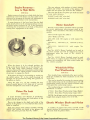
•
PAR T S
ACCESSORIES
•
PRODUCT
PACKARD DIVISION
OF
STUDEBAKER-PACKARD CORPORATION
VOL. 29, NO. 8
AUGUST, 1955
Carburetor Metering RodsJets-Repair Kits
55th Series
Listed below are th e Car buretor Assemb1y Numbers,
Metering Rods, Jets, Gasket and Repair Kits for the
55th Series cars.
dome cyli nder he ads, install the metering rods 75-1163 furnished in the kit.
474273
Part No.
440823
458988
458989
458982
4.58787
45 8 788
4760 10
476011
Descci plion
Models
No. R eq.
474272
458911
Carburetoe Assem hly
Rochester 4 GC
Carburetor Repair Kit
5560-80
(Not I1sed 5588)
5560-80
(Not used 5588)
Carburewc Gaske t Set
5560-80
(Not used 5588)
Metering Jet ( Primacy Std . )
2
5560-80
(Not used 5588)
Metering Jet (Primary Lean)
2
5560-80
(Not used 5588)
2
Metering Jet (Secondary
5560- 80
Std.)
(Not used 5588)
Carburetor Assembly
Ro c hes ter 4 GC (Fro m )
Carburetor Assembly
Rochester 4 GC (Rear)
474264
4742 65
Late Production 5540 Models
Used With Cast Dome
Cylinder Heads
5588
5588
Part No.
474046
Early Production 5540 Models
Used With Machined Dome
Cylinder Heads
Part No.
Description
474046
Carbu retor Replacem ent Kit
Carter \X!CF B-22 84 S
Models
Carburetor Repair Kit
WCFB-2232 S
5540
1
Carburetor Gasket Set
5540
1
Metering Rod
5540
2
Standard (75-1163)
Mete ring Rod
5540
2
One Size Lean (75-1211)
Metering Rod Kit
5540
1
Two Sizes Lean (75·1213 U) Secondary Jets must
be changed wit h two size Jeane r metering rods
Descriptio n
Carburetor Replacement Kit
Carter \X'CFB-22B 4 S
Models
No. Req.
5540
NOTE: The metering rods in the carburetOr are correct
for engines with cast dome heads, discard the meteri ng rods
75-1163 furnished with the kit.
474274
474272
474156
No. Req.
5540
474260
NOTE: Carrer Carburetor WCfB-2284 S replaces WCFB~
2232 S which was original equipment on 5540 models with
machined dome cylinder heads. When installing the Carburetor R eplacement Kit WCFB-2284 S o n engines with machine
47426 1
Carb uretor Repair Kit
1
55 40
WCFB-228 4 S
1
Carburetor Gasket Set
5540
Metering Rod
5540
2
Standard (75-1170)
Metering Rod
2
5540
One Size Lean (75-1195)
Metering Rod Kit
5540
Two Sizes Lean (75 - 1197 U) Secondary Jets must
be changed with tw O size leaner metering r ods
39
The Packard Library (http://www.thepackardlibrary.com)
Engine RunawayLow to High Shifts
The new pistons with numbers 473324, 476041,
476045 and 476047 cast inside of the pistons will
require the new piston pin lock Part No. 440995.
The wire size of the two piston pin locks are listed
for your ready reference.
#440847 Lock (.080" wire size)
#440995 Lock (.063" wire size)
55th Seri es
Engine runaway during low to high shifts has been
reported on a few 55th Series cars, that could not be
corrected by changing the throttle rod adjustment to
raise the throttle pressure in the transmission.
In some instances, it has been found that tbe high
range clutch piston in the released position rests on
the milled surface indicated by " B" in the illustration
restricting the oil pressure to the back of the piston
causing slow engagement of the clutch.
Motor Camshaft
Part No. 419432 Motor Camshaft will be cancelled
for service replacement when present stock is ex·
hausted. This cancellation will affect the following
models:
2302-32 with engine No. suffix F.
2401-Bodies 24 6 7-69.
2401·2501 with 300 engine or with englne No.
suffix H.
2402-06-13, 2502 -06-13-31, 2602-06-13-26-31,
5402.
2601-11-33, 5400-01-11- 3 3 with engine No.
suffix H.
Part No. 465074 Motor Camshaft can be used in
the above models and will be shipped for service
replacement when the stock of No. 419432 is
exhausted.
Part No. 419432 Motor Camshaft canlJot be used
in the 359 cu. in. engines in place of Part No. 465074,
because the connecting rod bolts would strike the
No . 419432 camshaft.
When the piston is in irs released pOSltlOn, the
flange on the piston should rest on the shoulder " A"
in the high range clutch housing, leaving .031"
clearance between the end of the piston and the milled
surface marked "B" which provides a means for the
oil -pressure to engage the clutch.
Windshield Pillar
Post Weatherstrip
55th Series
New moulded type windshield pillar post weather·
strips are available for field installation on the 55th
Series Cars.
They can be installed by coating the contact surface
on the weatherstrip and the windshield post with 3M
weatherstrip cement, after the cement becomes tacky
firmly press the weatherstrip in place.
The weatherstrips are available t hrough your Zone
Warehouse as listed:
If the piston is found to be touching or resting on
the milled surface "B" in the clutch housing, oil
passages can be provided by filing four grooves in
the piston as shown .
Using the edge of a 12" file, carefully file four
grooves equally spaced 1/ 16" deep and ).::1" outward
from the champhered center hole in the piston.
Piston Pin Lock
475244
475245
55th Series
Front Door Weatherstrip (Upper Right)
Front Door Weatherstrip (Upper Left)
NOTE: Cut off upper end of weatherstrips to proper
length when using on bodies 554 7-67 -8 7-88.
A recent alteration, now effective in production,
revised the size of the piston pin lock groove in the
piston and the lock wire size.
Due to the change in the depth and width of the
groove in the piscon, it is very import(l11t that correct
locks be installed .
Electric Window Shaft and Pinion
Early type pistons with numbers 440585, 440586,
440587 and 440588 cast inside of the pistons will
require the piston pin lock Part No. 440847.
A number of reports have been received of the
electric window lift transmission pinion gears com·
ing loose from the pinion shafts . .
55th Series
40
The Packard Library (http://www.thepackardlibrary.com)
New type shaft and pinion assemblies made from
one piece of stock are now used in production and are
available for field installation.
Production has discontinued the dip stick and are
placing a decal on the top of the reservoir with instructions to maintain the fluid level to the top of the
filter element.
One shaft and pinion will fit either a front or rear
door and are the same for all models.
The filler cap has been redesigned to prevent the
slight oil leak through the vent.
The new type shaft and pinion assembly can be
ordered under Part Number 4 74388.
The new caps are available through your Zone
Warehouse under Part Number 4 74071.
Torque Specification Change
55th Series
Twin Ultramatic Transmission Fluid
Please refer to your Service Technical Bulletin
55T-4, Dealer 4, January 19, 1955 and to the torque
specifications that were attached to Service Technical
Bulletin 55T-8, Dealer 7,January 31 , 1955.
Production started using a new improved Ultramatic Transmission Fluid at the stan of the 55th
Series Twin Ultramatic Transmission.
This new fluid can be distinguished by its greenishblue cast. It has improved anti-friction properties
which result in better clutch plate durability and also
less wear of metallic surfaces. The new fluid has a
Pour Point close to 60° F. below zero which insures
satisfactory transmission performance in the coldest
weather.
In Service Technical Bulletin 55T-4, change item 2
to read 50 ill. Ibs. instead of 20 in.lbs.
In the last item under Twin Ultramatic Transmission
torque specifications add the following: " Back off the
flange bolt a turn or two and retorque it to 50 in. lbs.
The flange bolt torque specifications are correct as
described on page 49 in the Twin Ultramatic Section
of your new Service Manual.
This new fluid may be mixed with any type "A"
automatic transmission fluid which has an AQ-AFT
number embossed on the top of the can. However,
we recommend that the new type fluid be used and it
is available at the Central \Varehouse in quarts, gallons,
5 gallon and 55 gallon drum lots.
Crankshaft Identification
55th Series
Please refer to your Service Counselor Vol. 29, No.
5, May 1955 on the above subject.
Service Manual Corrections
55th Series
The crankshafts with a number "4" stamped on a
milled surface on one end of the front counterweight
may be used in wther the 4" or 3-13 / 16" bore engines.
Please refer to the Engine Section in your new 55th
Series Service Manual and make the following corrections:
The cral1kshajts sta mped with the Jlumber ·'3" call
ol1ly be used ill tbe 3-1 3/16" bore e1Jgilles.
On page 1 under DESCRIPTION, change 3-3/ 16"
bore to read 3-13/ 16" bore.
On page 32 under ENGINE SPECIFICATIONS,
change Bore and Stroke 3.1825 '1 x 3.5" to read Bore
and Stroke 3.8125" x 3.5".
Spark Plug Fouling
55th Series
Please make the same corrections on the same pages
in your Serviceman's Training Book "Clipper-Packard
V -8 Engines."
Spark plug " cold fouling" may be encountered
occasionally in 55th Series cars that are driven at low
speeds for prolonged periods.
1\ one step hotter spark plug (Champion H-ll) has
been released for service to aid in the elimination of
the cold fouling condition. These hotter spark plugs
are available for the 5560 and 80 models and the early
5540 models with the mathined cylinder head combustion chamber and may be ordered under Part No.
532268.
Please refer to your Service Technical Bulletin
55T-8, Dealer 7, January 31, 1955.
Power Steering Pump Reservoir
Two additional torque specifications have been
released for service and should be added to the
torque specifications under "Suspension."
Torque Specifications-Additions
55th Series
a. Front Support Arm (Lower) Inner BushingIJ,i 145-155 Ibs. ft.
.
55th Series
A few reports have been received of the dip stick
breaking loose from the filler cap and slight oil leaks
through the vent on the cap.
b. Front Support Arm (Upper) Inner Bushing
115-125 Ibs. ft.
lYs
41
The Packard Library (http://www.thepackardlibrary.com)
I
Horn Button Contact
Two states, Florida and Georgia, while approving
in general rhe new Sealed Beam units and permitting
rheir use, require that the units be aimed 311 below the
light centerline at 25 feet rather rhan 2 11 as recommended by the manufacturers. ]f you are nor sure
about the legal headlight aim specification in your
state, check with local or state police authorities.
55th Series
A few reports have been recei ved of the horn button
not making contact when the horn ring is pushed
down at the location in line with the spoke of the
steering wheel.
Above all else, aim the headlamps accurately and
keep them clean . Mis-aim, of even a small amount,
will literally steal away a large pan of the improved
lighting designed into the Sealed Beam head lamps
and may seriously glare the oncoming driver. " Accuracy" means within a small fraction of a degree,
because an error of a half degree results in a misaim of 5 feet at a distance of 600 feet ahead of the
vehicle. The dust and din accumulated in half an
evenings driving may easily reduce illumination 50
per cent.
This condition can be corrected by installing spacers and longer screws between the steering wheel
and the horn ring contact plate as follows:
1. Pry out the horn button and remove rhe steering
wheel assembly.
2. Remove the three screws that attaches the contact plate to the steering wheel, install rhe three
spacers No. 6480674 behind the plate and secure the
plate with the three new longer screws No. G -166580.
"See illustration."
For aiming instructions, refer to the electrical section "Head lamp Aiming" in your new 55th Series
Service Manual.
NOTE: The new scaled beam headlights have been
approved in Idaho and Texas but the act is not effective at this writing. Consult your local or state police
authorities as to the effective date.
Windshield Glass Squeaks
55th Series
G 1665 80
SC REW S ( 3 )
64a 0674
SPACER
Occasionally, squeaks or grunts will develop between the windshield glass and weatherstrip while
driving over rough roads , especially if-the glass is not
centered in the weatherstrip.
Beginning July 18th, with the following vehicle
numbers: 5522-7802, 42- 7915, 47-7033, 62-8431,
67-7012 , 82-9265, 8 7-7230, 88-1493, production
starred using Sealzit between the glass and weatherstrip to prevent the squeak and grunt.
(3)
3. Align t he steering wheel in the straight ahead
position, tighten it securely and reinstall the horn
It is suggested, on those cars prior to the \'ehicle
numbers listed above, in which the squeaking and
grunting of the windshields occurs and where the
glass creeps out of the weatherstrip, that Sealzit be
used.
button.
"The spacers and longer screws may be ordered as
fo llows :
Part No.
6480674
G -166580
Description
Spacers
Screws
No. Required
3
3
The windshield mouldings should be removed so
that the glass can be shifted to properly center it in
the weatherstrip. Using a putty knife, pry the weatherstrip away from the glass and work the Sealzit down
in the weatherstrip as far as possible.
New Style Sealed Beam
Headlights
Winds h ield Sealzit, Part No·s. PA 41035 7 and PA
410857, are listed in the Accessories Section of your
Parts Book.
New improved Sealed Beam headlight units with
shielded upper filame nts, revised lenses, and increased wattage will be factory installed on new
vehicles shortly after July 4th, and are being sold for
use in all states.
Cylinder and Piston Assembly
55th Series
Serv ice replacement cylinder and piston assemblies
for the 55th Series engines are made up for the Twin
UJtramatic Transmission .
The new type Sealed Beam units are available from
your Studebaker-Packard Parts Depots for use as a
service replacement. The new units are stocked by
all depots under Part No. 458921 for cars with 6-volt
electrical sys tems or Part No. 472164 for 12-volt
systems. Use the new type units in pairs only on
initial installations.
When installing a cylinder and piston assembly on
standard transmission or overdrive equipped cars,
the only change necessary is to remo ve and discard
the dowel located in the upper flange of lhe bell
housing.
42
The Packard Library (http://www.thepackardlibrary.com)
PRIN TED IN U.S.A.