1
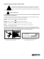
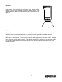
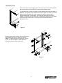
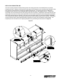
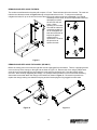
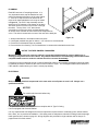
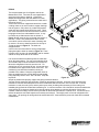
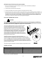
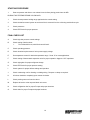
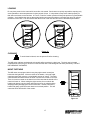
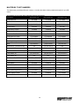
Installation & Operations Manual for
MDT SERIES
Open Display Merchandisers
PN 063-90000
Rev 1-28-10LN
2
TABLE OF CONTENTS
Page Numbers
INTRODUCTION………………………………….……………………………………………………………………4
WARNING LABELS AND SAFETY INSTRUCTIONS………..…..……………………………………………… 5
PRE-INSTALLATION INSTRUCTIONS………………………..…..………………………………….…………… 6
Spection for ShippingDamage……………………………………………………….………………………… 6
INSTALLATION INSTRUCTIONS………………………………………………………………………………….. 6
Store Conditions………..…………………………….…………………………………….…………………… 6
Location…………………………………………………………………………………….. ………………….…7
Leveling………………………………………………………………………………………………..…………. 7
Joining Sections…………………………………………………………………………………..……………… 8
Installing Joining Trim MD…………………………………………………………………….………………... 9
Installing Joining Trim MDT…….……………………………………………………………….…………….. 10
Installing the Endskirts and Kickplate………………………………………………………………..……….. 11
Removing and Replacing Bumper Trim………………………………………………………………………. 11
Removing and Replacing the Ends……………………………………………………………………….…. 12
Removing and Replacing the Canopy………………….…………………………………………………….. 12
Plumbing…………………………………………………………………………………………………………. 13
Electrical……..…………………………………………………………………………..………………………. 13
Piping…………………………………………………………………………………………………………….. 14
Refrigeration System Evacuating and Charging…………………………………………………………….. 15
EPR Valve/Temperature Control……………………………………………………………………………… 15
Control Settings…………………………………………………………………………………………………. 15
STARTING PROCEDURE…………………………………………………………………………………………... 16
FINAL CHECK LIST………………………………………………………………………………….………………. 16
LOADING……………………………………………………………………………………………………………… 17
CLEANING…………………………………………………………………………………………………………….. 17
NIGHT CURTAINS……………………………………………………………………………………………………. 17
SERVICE INSTRUCTIONS………………………………………………………………………………………….. 18
MASTER-BILT PART NUMBERS………………………………………………………………………………….. 19
SALE AND DISPOSAL………………………………………………………………………………………………. 20
WIRING DIAGRAMS.…………………………………………………………….……………………….……….21-23
MD REFRIGERATION SIZING CHART……………………………………………………………………………. 24
3
INTRODUCTION
Thank you for purchasing a Master-Bilt cabinet. This manual contains important instructions for installing, using
and servicing a Master-Bilt MD series endless open air case. Read all these documents carefully before installing
or servicing your equipment. This manual should be left in the care of the store owner or manager.
NOTICE
Read this manual before installing your cabinet. Keep the manual and refer to it before doing any service
on the equipment. Failure to do so could result in personal injury or damage to the cabinet.
DANGER
Improper or faulty hook-up of electrical components of the refrigeration units can result in severe injury or
death.
All electrical wiring hook-ups must be done in accordance with all applicable local, regional or national
standards.
NOTICE
Installation and service of the refrigeration and electrical components of the cabinet must be performed by
a refrigeration mechanic and/or a licensed electrician.
The portions of this manual covering refrigeration and electrical components contain technical instructions intended
only for persons qualified to perform refrigeration and electrical work.
This manual cannot cover every installation, use or service situation. If you need additional information, call or
write us:
Customer Service Department
Master-Bilt Products
Highway 15 North
New Albany, MS 38652
Phone (800) 684-8988
Fax (800) 684-8988
4
WARNING LABELS AND SAFETY INSTRUCTIONS
This symbol is the safety-alert symbol. When you see this symbol on your cabinet or in
this manual, be alert to the potential for personal injury or damage to your equipment.
Be sure you understand all safety messages and always follow recommended precautions
and safe operating practices.
NOTICE TO EMPLOYERS
You must make sure that everyone who installs, uses or services your cabinet is thoroughly familiar with
all safety information and procedures.
Important safety information is presented in this section and throughout this section and throughout the manual.
The following signal words are used in the warnings and safety messages:
DANGER:
Severe injury or death will occur if you ignore the message.
WARNING: Severe injury or death can occur if you ignore the message.
CAUTION: Minor injury or damage to your cabinet can occur if you ignore the message.
NOTICE:
This is important installation, operation or service information. If you ignore the
message, you may damage your cabinet.
The warning and safety labels shown throughout this manual are placed on your Master-Bilt Products
cabinet at the factory. Follow all warning label instructions. If any warning or safety labels become lost or
damaged, call your customer service department at (601) 534-9061 for replacements.
CAUTION!
GROUND REQUIRED
FOR SAFE OPERATION
This label is located on top of the electrical control
label and on the wiring channel.
This label is attached to the cabinet power cord
on models with a power cord.
5
PRE-INSTALLATION INSTRUCTIONS
INSPECTION FOR SHIPPING DAMAGE
You are responsible for filing all freight claims with the delivering truck line. Inspect all cartons and crates for
damage as soon as they arrive. If damage is noted to shipping crates or cartons or if a shortage is found, note this
on the bill of lading (all copies) prior to signing.
If damage is discovered when the cabinet is uncrated, immediately call the delivering truck line and follow up the
call with a written report indicating concealed damage to your shipment. Ask for an immediate inspection of your
concealed damage item. Crating material must be retained to show the inspector from the truck line.
INSTALLATION INSTRUCTIONS
GENERAL INSTRUCTIONS
1. Be sure the equipment is properly installed by competent service people.
2. Keep the equipment clean and sanitary so it will meet your local sanitation codes.
3. Rotate your stock so that older stock does not accumulate. A "First-In, First-Out" rotation practice will keep the
products in good salable condition.
4. Product should not be put in the case for at least 6 hours after it is started.
5. Stock cases as quickly as possible, exposing only small quantities to store temperatures for short periods of
time.
6. When replacing burned out fluorescent tubes, be sure that the electrical power to the lighting circuit is turned off.
STORE CONDITIONS
The Master-Bilt MD cases are designed to operate in the controlled environment of an air conditioned store. The
store temperature should be at or below 75°F and a relative humidity of 55% or less. At higher temperature or
humidity conditions, the performance of these cases may be affected and the capacity diminished. It is not
uncommon in a newly constructed store for the temperature and humidity to be above design conditions. These
excessive conditions may produce sweating in the case until the store is operational and the ambient environment
is more desirable.
The Master-Bilt MD-06/08 should not be positioned where it is directly exposed to rays of the sun or near a direct
source of radiant heat or air flow. No HVAC return or supply air ducts may be located near case openings. This will
adversely affect the case air flow and will result in poor performance. Do not open windows or doors that will affect
the case air flow. The maximum air velocity near the case air return is 50 FPM. If this case is to be located against
a wall there should be at least a 6” space between the wall and the back of the case. This space will allow for the
circulation of air behind the case which will prevent condensation on the exterior surfaces.
These cases should always be loaded properly. This unit will operate differently when loaded or unloaded. Consult
the section of this manual that specifies loading procedures.
A P-trap is included with each case. It is important that each case has a P-trap installed. Consult the section of
this manual for installing and piping the drain.
To comply with Sanitation requirements; the cabinet must be mounted on legs (6” high min.) or casters or the base
must be sealed to the floor (MDT) with an N.S.F. listed silicone sealant. Minimum clearance allow at least a 4”
space between the wall and the back of the case. This space will allow for the circulation of air behind the case
which will prevent condensation on the exterior surfaces.
6
LOCATION
Make sure that the floor will support this equipment is of adequate strength to
prohibit sagging. After confirming the dimensions of case, measure off and
mark on the floor the exact location of the cases for the entire lineup. Snap
chalk lines where the base skids of the case are to be located as shown in
Figure 1.
Figure 1
LEVELING
It is very important that this equipment be perfectly level. This will allow for proper and complete drainage of the
evaporator coil and for proper case alignment. A perfectly level area is generally not available where the
equipment is to be installed. Mark the location of all case joining points front and back. Use a transit to locate the
highest point on the chalk lines. This point will be a reference point for determining shim-pack heights. Using the
reference point, mark the difference directly on the floor to each joining point front and back. Shim each joining
point to equal the reference point as required. Tape all shims in place. If the installation is an entire lineup install
the case that will be positioned at the highest point first. Check that the equipment in the lineup is level as the
installation proceeds.
7
JOINING SECTIONS
Remove the case from its shipping skid. Set the first case into its desired position
with required shims in preparation for joining it with its adjacent case.
The joining gasket for cases in a lineup is factory installed and is shown in black in
Figure 2. This gasket is only required on one end of cases in a lineup as only one
gasket is needed between two cases. Inspect the gasket to insure that it is
properly located and is not damaged. The cases are now ready to be joined
together. Remove the second case from its shipping skid and move it into position
against the end of the first case. Properly level the second case with the
appropriate shims
Figure 2
Bolt the cases together through the seven holes that
are provided in the steel end frame as shown in
Figure 3. Tighten the bolts until all seams are fully
closed. Do not over tighten. Repeat the above
process for all other cases in the lineup.
Figure 3
8
INSTALLING JOINING TRIM, MD
A trim kit for joining sections consists of three pieces: the canopy joiner trim, the frontwall joiner trim, and the
kickplate joiner trim. Begin by removing all of the bumper trim and retainers on the canopy and the frontwall. Refer
to the section of this manual for removing and replacing bumper trim. The canopy joiner trim is attached by
locating the holes in the top of the canopy that will line up with the holes in the canopy joiner trim. Remove the
screws that are in the canopy and move the canopy joiner trim into position. Replace the screws that will retain the
canopy joiner trim at the top. Now, mark and drill two 1/8” dia. holes in the bottom of the canopy where the bottom
holes of the canopy joiner trim will align. Pop rivet the trim into place using 1/8” pop-rivets as shown in Figure 4.
The frontwall trim will attach to the frontwall using a good two-sided adhesive tape or silicon caulking. The bumper
on the top and the front of the frontwall will help to hold this trim in place, but an adhesive is also needed. The
kickplate joiner trim will attach to the adjoining kickplates using self-drilling screws as shown in Figure 4.
Figure 4
9
INSTALLING JOINING TRIM, MDT
A trim kit for joining sections consists of three pieces: the canopy joiner trim, the frontwall joiner trim, and the
kickplate joiner trim. Begin by removing the bumper trim and retainers on the frontwall. Refer to the section of this
manual for removing and replacing bumper trim. The canopy joiner trim is attached by locating the holes in the top
of the canopy that will line up with the holes in the canopy joiner trim. Remove the screws that are on the
underside of the canopy and move the canopy joiner trim into position. Replace the screws that will retain the
canopy joiner trim at the bottom. Use #10 self-drilling screws to secure the canopy joiner trim at the top. The
frontwall trim will attach to the frontwall using a good two-sided adhesive tape or silicon caulking. The bumper on
the top and the front of the frontwall will help to hold this trim in place, but an adhesive is also needed. The
kickplate joiner trim will attach to the adjoining kickplates using sheet metal screws as shown in Figure 5.
Figure 5
CANOPY
JOINER TRIM
FRONTWALL
JOINER TRIM
KICKPLATE
JOINER TRIM
10
INSTALLING THE ENDSKIRTS AND KICKPLATE
The kickplate should be installed prior to attaching the endskirts.
The endskirts are shipped loose. Secure the kickplate to the
flange of the wire raceway using the supplied sheet metal screws.
Use the supplied sheet metal screws to secure the kickplate to
the bottom edge of the frame and the electrical raceway. The
bottom of the kickplate should be in contact with the floor. Refer
to Figure 6 for the placement of the Kickplate. The endskirt will
attach to the ends of the lineup using the supplied #10x1/2 self
drilling screws as shown in Figure 6.
Figure 6
REMOVING AND REPLACING BUMPER TRIM
All of the bumper trim on the MD line is of the same type. To remove a section,
begin at one end and unsnap the bumper from the retainer. A screwdriver may
have to be used to get the bumper started as shown in Figure 7. Use the proper
safetey precautions when removing the bumper. The endcaps and the the
bumper retainer can now be removed by removing the screws that attach the
pieces to the cabinet. Be sure to use the same type screws to replace the
retainer and the endcaps.
Figure 7
11
REMOVING AND REPLACING THE ENDS
The ends are manufactured so that they will accept a 1/2” bolt. These bolts should not be removed. The ends are
bolted to the cabinet as shown in Figure 8 through a keyslot rather than a hole. To remove an end simply
untighten the bolts, lift up on the end and remove the end from the cabinet as shown in Figure 9. If you should
accidently remove a bolt, be sure to replace the bolt before
attempting to replace
the end onto the end
frame. When
replacing an end make
sure that the cabinet is
completely sealed but
do not overtighten the
bolts and remember to
inspect the gasket
material prior to
replacement. Reverse
the procedure to
replace the ends.
Figure 8
Figure 9
REMOVING AND REPLACING THE CANOPY (MD ONLY)
Before the canopy can be removed, the light bar must be unplugged from the cabinet. There is a light plug access
cover on the top of the canopy on the right end as shown in Figure 10. Remove this cover using a phillips head
screw driver to reveal the light plug and unplug the male end from the female end. Now the canopy can be
removed. While carefully supporting the canopy, use a phillips head screwdriver to remove the #10 self-drilling
sheet metal screws that attach the canopy to the cabinet as shown in Figure 11. Reverse this procedure to
replace the canopy making sure that the male plug and the female plug are fully plugged into each other.
Figure 10
Figure 11
12
PLUMBING
Each MD case has a P-trap shipped loose. It is
very important that this trap be installed as it will
result in diminished peformance of the case without
it. There is a P-trap access cover which can be
removed for better admittance to the trap as shown
in Figure 12. The PVC P-trap assembly must be
glued to the PVC adapter on the bottom of the drain.
The drain can be run to the front or back or through
the skids. The top of the 1-1/2” drain can be
accessed by removing the center insulated bottom panel.
An access cover can then be removed from the evaporator fan
cover. The drain is located at the center of the case in the drain pan.
1.
2.
3.
4.
Figure 12
Always install drains in accordance with local codes.
Use largest possible size pipe for drains, 1-1/2” minimum is recommended.
Provide as much downhill slope as possible.
Prevent drains from freezing. Do not install drains in contact with uninsulated suction lines.
NOTICE TO STORE OWNERS / MANAGERS
Moisture or liquid around or under the cabinet is a potential slip/fall hazard for persons walking by or
working in the general area of the cabinet. Any cabinet malfunction or housekeeping problem that creates
a slip/fall hazard around or under the cabinet should be corrected immediately.
If moisture or liquid is observed around or under a Master-Bilt cabinet, an immediate investigation should be made
by qualified personnel to determine the source of the moisture or liquid. The investigation made should determine
if the cabinet is malfunctioning or if there is a drain pipe leaking.
ELECTRICAL
WARNING
Before servicing electrical components in the case make sure all power to case is off. Always use a
qualified technician.
NOTICE
For models with electronic ballast only:
For replacement ballast, use only ballast that complies with UL Type CC rating
if unit is equipped with electronic ballast.
It is very important that full voltage and overcurrent protection requirements for condensing units, defrost heaters,
fans, doors, etc. be provided at installation. Wire sizing must be adequate to maintain full voltage under amperage
loads specified in the charts on page 24. Wiring diagrams are provided for single cabinets and for lineups on
pages 22 and 23 of this manual.
13
PIPING
The recommended type of refrigerant used in the
Master-Bilt is R-22. Line sizes for most applications
are given in the chart on page 24. Consult the
Master-Bilt Refrigeration Unit I&O Manual for other
applications. The piping connections are made at the
left end of the coil.
These lines have been capped and should be cut with
a tubing cutter so as not to introduce copper shavings
into the system. Only clean, dry, sealed refrigeration
grade AC hard copper tubing should be used. There
is a cutout near the front of the case which is used for
bringing the lines from underneath the case. It may
be easiest to pre-fabricate the lines as shown in
Figure 12 and insert the line up through the bottom of
the case. If this is not possible there is an access
cover which can be removed for ease of brazing and
for service. Be sure to install a suction line oil trap or
‘P-trap as shown in Figure 13. The skids are
designed with a
cutout in the rear of the skid for running refrigeration
piping through the skids as shown in Figure 14. There
is ample room for piping for the MD/MDT and for another
cabinet or lineup at the rear of the cabinet.
Figure 13
It is recommended that all brazed joints be made with
silver alloy-type solders. For roof top condensing units,
an inverted P-trap must be installed in the suction line
where the refrigeration lines exit onto the roof. For
vertical line runs of more than 20 feet., a riser trap must
be installed at the approximate center of the riser. The
condensing unit should be located as closely as
possible to the cabinet. Keep the refrigeration lines as
short as possible and use as few fittings as practicable,
being especially careful not to “kink” the lines. Keep the
layouts as
Figure 14
simple as possible and properly support the piping to absorb vibration
and the normal expansion and contraction caused by temperature changes. All suction lines should be wellinsulated to minimize heat absorption and control condensate which could form on the suction line. If tubular
insulation is used, the ends, joints, and any other open areas (including slits necessary to fit the tubing over
installed piping) should be sealed with insulation glue. A minimum amount of flux should be used as needed and a
small amount of dry nitrogen should be fed into the tubing during brazing to minimize formation of scale and
oxidation inside the tubing. Leak check all joints with an electronic leak detector or halide torch. If leaks are found
relieve the pressure and make repairs as necessary and recheck. Thoroughly caulk or foam all refrigeration line
entry holes. All openings for wiring should be sealed with N.S.F. listed sealant to prevent air leaks and unwanted
condensation.
14
REFRIGERATION SYSTEM EVACUATING AND CHARGING
1. Blow out all refrigerant lines with dry nitrogen or carbon dioxide to eliminate the possibility of
dirt, scale, etc. remaining inside.
2. Connect all lines and leak test all connections.
3. Connect a good high vacuum pump to both the low and high side service valves.
4. Operate the pump until a vacuum of 1500 microns (0.06 inches of mercury) absolute pressure is obtained. At
this point, the vacuum should be broken by the introduction of refrigerant into the system, through a drier, until
the pressure is brought up to zero pounds gauge. Repeat this procedure two more times. During the final
evacuation, a vacuum of 500 microns (0.02 inches of mercury) absolute pressure should be obtained. After
this vacuum is reached, the system can be fully charged with refrigerant.
EPR VALVE/ TEMPERATURE CONTROL
NOTICE
The evaporator pressure regulator valve (EPR valve) is not used to control temperature in the MD case.
This cabinet is equipped with a temperature control which should be properly field wired as a control for
the system. Refer to the wiring diagrams on pages 21 to 23 of this manual.
The factory installed temperature control is located at the right
end of the evaporator fan cover as shown in Figure 14. This
control can be exposed and adjusted by removing the bottom
panels at the bottom of the case. It is not necessary to open the
evaporator fan cover to access these controls. The sensing bulb
for the temperature control is located between the evaporator fan
covers and the fan housing in the return air. The temperature
control is adjusted by simply turning the knob clockwise for a
colder case and counter-clockwise for a warmer case. The temp
control should be set so that it cycles off when the discharge air at
the honeycomb reaches 24-26°F.
The EPR valve should not be used to control temperature. It is
installed to prevent the evaporator pressure from becoming too low in the
event of low charge, low temperature control settings, or a failed temperature
control. If the EPR valve is not properly installed the evaporator coil could begin
to ice. Actual settings will vary from location to location depending on ambient
conditions but the EPR valve should be set so that the evaporator pressure will not
go below 47-58 lbs for R-404a.
Figure 14
This will insure that the evaporator coil doesn’t operate at a temperature too low.
CONTROL SETTINGS
EPR Valve setting
Temperature Control - Air Discharge Temperature
45 - 60 psig
24-26°°F at honeycomb
Condensing Unit Defrost Settings
4 times/day (6 hours); 30 minutes fail safe
Condensing Unit Low Pressure Control
Cut in – 20 lbs*: Differential 16 lbs
Condensing Unit High Pressure Control
425 lbs
*This is a standard setting; extreme cold climates may necessitate that the low pressure control be set
to a 4 lb cut-out and 20 lb. differential.
15
STARTING PROCEDURE
1.
Start compressor and allow to run at least 6 hours before placing product into the MD.
DURING THIS TESTING PERIOD YOU SHOULD:
1.
Check the temperature holding range against the the control setting.
2.
Check the defrost control system to see that all ice is removed from the coil during each defrost cycle.
3.
Check pressures.
4.
Check EPR Valve for proper pressure.
FINAL CHECK LIST
A.
Check high-low pressure control settings.
B.
Check setting of defrost timer:
1.
Four defrost/24 hours, with 30 minutes fail safe.
C.
Check operating pressure.
D.
Check electrical requirements of unit to power supply voltage.
E.
Set temperature control for desired temperature range. Set at ‘6’ for most applications.
F.
Check setting of thermostatic expansion valve for proper operation. Appprox. 10°F superheat.
G.
Check sight glass for proper refrigerant charge.
H.
Check EPR Valve for proper pressure setting.
I.
Check system for proper defrost settings and operation.
J.
Check condensing unit for vibrating or rubbing tubing. Dampen or clamp as required.
K.
All valves should be completely open counter-clockwise.
L.
Check packing nuts on all service valves.
M.
Replace all service valve caps and latch unit covers.
N.
Check refrigeration line for proper P-traps and proper locations.
O.
Check drain for proper P-traps and proper locations.
16
LOADING
Do not place product in the case until 6 hours after it is started. Stock cases as quickly as possible, exposing only
small quantities to store temperatures for short periods of time. It is important to keep stock rotated properly so
that older stock does not accumulate. A “First-In, First-Out” rotation practice will keep the products in good sellable
condition. Avoid loading the case so that product sticks out beyond the shelves or blocking the return air grille at
the bottom of the case. This will interfere with the air flow of the case and will result in diminished performance.
Figure 15
CLEANING
To avoid electrical shock, turn the power off before cleaning.
The MD series cabinets are designed so that spills will accumulate in a drain pan. The drain pan is located
underneath the return air grill. Be sure to clean all areas with a mild detergent and water periodically. DO NOT
USE ABRASIVE CLEANERS.
NIGHT CURTAINS
The MD cases are equipped with a heavy duty night curtain located just
behind the the light bulbs. All that is visible is the handle. Using the night
curtains properly will conserve a considerable amount of energy. The night
curtains should be lowered when the store is closed or the case is not in use.
There is a hook mounted on the lower front of the case that the handle of the
curtain will catch in. When raising the night curtains, do not unhook the
handle and release it as the curtain will spring back into its raised position
abruptly possibly damaging the curtain or the case. Instead, unhook the
handle and gently guide the curtain back into its raised position. This will
extend the looks and the life of the curtain.
Figure 16
17
SERVICE INSTRUCTIONS (Trouble Shooting Guide)
1.
High head pressure and high back pressure:
A.
B.
2.
Low head pressure and low back pressure:
A.
B.
C.
D.
3.
F.
G.
H.
J.
Defrost heater not operating
P-trap in drain not installed
Air screen disturbance
Evaporator fan motor defective
Low voltage.
Dropped Phase (3 phase)
Overload protector defective.
High head pressure (see #1).
Relay or Capacitor Defective (1 phase)
Compressor will not start – hums, but cycles on overload:
A.
B.
C.
7.
Defective temperature control.
EPR valve set too low.
Time clock not operating properly.
Improper time clock setting
Ambient conditions above 75°F and 55%RH
Compressor starts and runs but cycles on overload:
A.
B.
C.
D.
E.
6.
Coil blocked with frost or ice (see #4).
Control set too warm.
Air screen disturbance.
Coil blocked with frost or ice:
A.
B.
C.
D.
E.
5.
Restriction in system.
Refrigerant undercharged.
Leak in system.
EPR valve set too low.
Pressures normal – cabinet warm:
A.
B.
C.
4.
Condenser coil clogged or restricted.
Condenser fan motor defective.
Low voltage.
Relay defective.
Overload protector defective.
D. Start capacitor defective.
E. High head pressure (see #1).
Special service situations:
If moisture or liquid is observed around or under a Master-Bilt cabinet, an immediate investigation should
be made by qualified personnel to determine the source of the moisture or liquid. The investigation made
should determine if the cabinet is malfunctioning or if there is a simple housekeeping problem.
Moisture or liquid around or under a cabinet is a potential slip/fall hazard for persons walking by or working
in the general area of the cabinet.
Any cabinet malfunction or housekeeping problem that creates a slip/fall hazard around or under a cabinet should
be corrected immediately.
18
MASTER-BILT PART NUMBERS
The table below gives Master-Bilt part numbers. Use this chart when ordering replacement parts for your MD
cases.
All quantities are one each unless otherwise noted by parentheses.
Description
MD-04/MDT-04
MD-06/MDT-06
MD-08/MDT-08
Evaporator Coil
07-13230
07-13209
07-13199
Expansion Valve
09-09478
09-09468
09-09468
Defrost Heater
(2) 17-09273
(2) 17-09258
(2) 17-09259
Heater Safety
19-01307
19-01307
19-01307
Temperature Control
19-00844
19-00844
19-00844
Evaporator Fan Motor
(2) 13-13124
(2) 13-13124
(3) 13-13124
Evaporator Fan Blade
(2) 15-13092
(2) 15-13092
(3) 15-13092
Evaporator Fan Guard
(2) 25-00205
(2) 25-00205
(3) 25-00205
Drum Thermometer
19-13586
19-13586
19-13586
Discharge Honeycomb Insert
29-01517
(1.5) 29-01517
(2) 29-01517
(8) 33-01533
(12) 33-01533
(16) 33-01533
Standard 24” Flourescent Lamp
N/A
(2/1) 23-01576
N/A
Standard 36” Flourescent Lamp
(2/1) 23-01577
(2/1) 23-01577
(2/1) 23-01577
Standard 48” Flourescent Lamp
N/A
N/A
(2/1) 23-01575
Lamp Shield, 36”
(2/1) 25-01274
(4/2) 25-01274
(2/1) 25-01274
Lamp Shield, 48”
N/A
N/A
(2/1) 25-01311
23-01704
(2/1) 23-01704
(2/1) 23-01704
Lampholder
(4/2) 23-50562
(8/4) 23-50562
(8/4) 23-50562
Lamp Switch
23-50793
23-50793
23-50793
Night Curtain, 4’
56-00058
N/A
(2) 56-00058
Night Curtain, 6’
N/A
56-00059
N/A
(2) 56-00061
(2) 56-00061
(5) 56-00061
Curtain Spindle Holder
56-00060
56-00060
(2) 56-00060
Curtain Hold Down Hook
56-00050
56-00050
(2) 56-00050
Shelf
Ballast
Curtain Mounting Bracket
19
SALE AND DISPOSAL
OWNER RESPONSIBILITY
If you sell or give away your Master-Bilt cabinet you must make sure that all safety labels and the Installation Service Manual are included with it. If you need replacement labels or manuals, Master-Bilt will provide them free.
Contact the customer service department at Master-Bilt at (800) 684-8988.
The customer service department at Master-Bilt should be contacted at the time of sale or disposal of your cabinet
so records may be kept of its new location.
20
21
22
23
2
1
12'-4'
14'-4'
16'-4'
18'-4'
20'-4'
22'-4'
24'-4'
26'-4'
28'-4'
30'-4'
12'0"
24
14'0"
16'0"
18'0"
20'0"
22'0"
24'0"
26'0"
28'0"
30'0"
3
1
2
3
1
2
1
10'-4'
10'0"
1
8'-4'
8'0"
1
6'-4'
6'0"
1
4'-4'
4'0"
3
2
1
3
2
1
2
1
1
ZB38KCE
ZB38KCE
CS33K6E
CS33K6E
CS27K6E
CS27K6E
CS27K6E
CS20K6E
CS18K6E
CS12K6E
CS10K6E
CS10K6E
MSHZ0581C ZB45KCE-TF5
MSHZ0581C ZB45KCE-TF5
MSHZ0501
MSHZ0501
MHHZ0501
MHHZ0501
MHHZ0431
MHHZ0431
MHHZ0431
MHHZ0331
MHHZ0301
MHHZ0191
MHHZ0171
MHHZ0171
MDT-04 MDT-06 MDT-08 100°F**
Compressor
UNIT UP TO
OVERALL
LENGTH*
Suction,
AMBIENT
TOTAL
UNIT 100°F
39600
39600
33400
33400
28000
28000
23900
23900
23900
17200
15600
10300
8720
7500
ZB38KCE
ZB38KCE
CS33K6E
CS33K6E
CS27K6E
CS27K6E
CS20K6E
CS14K6E
CS14K6E
Compressor
BSHZ0750C
BSHZ0750C
BSHZ0750C
ZB56KCE-TWC
ZB56KCE-TWC
ZB56KCE-TWC
MSHZ0581C ZB45KCE-TF5
MSHZ0581C ZB45KCE-TF5
MSHZ0501
MSHZ0501
MHHZ0501
MHHZ0501
MHHZ0431
MHHZ0431
MHHZ0331
MHHZ0221
MHHZ0221
Condensing TO 120°F**
120F
HIGH
+15F
NORMAL
AMBIENT
R404A
R404A
MODELS REQUIRED
37400
37400
37400
30300
30300
24900
24900
19200
19200
15300
15300
10800
8000
8000
Condensing
140F
Suction,
+15F
MD REFRIGERATION SIZINING CHART