1
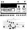
5314A
UNIVERSAL COUNTER
OPERATING AND SERVICE MANUAL
This manual applies directly to HP Model 5314A
having serial number prefix 1828A and below.
This manual, with enclosed “Manual Changes” sheet,
applies to HP Model 5314A having serial number
prefixes as listed on the “Manual Changes” sheets.
Copyright
5301
STEVENS
HEWLETT-PACKARD
CREEK
BLVD.,
SANTA
COMPANY
CLARA, CALIF.
1978
95050
MANUAL PART NUMBER 05314-90001
Microfiche Part Number 05314-90002
Printed: SEPT 1978
HEWLETT
Model 5314A
Safety Considerations
SAFETY CONSIDERATIONS
GENERAL
This is a Safety Class I instrument. This instrument has been designed and tested according to IEC
Publications 348, “Safety Requirements for Electronic Measuring Apparatus.”
BEFORE APPLYING POWER verify that the power transformer primary is matched to the available
line voltage and the correct fuse is installed (see Section II). Make sure that only fuses with required rated current and of the specified type (normal blow, time delay, etc.) are used for replacement. The use of repaired fuses and the short-circuiting of fuseholders must be avoided.
Although this instrument has been designed in accordance with international safety standards,
this manual contains information, cautions, and warnings which must be followed to ensure safe
operation and to retain the instrument in safe condition. Service and adjustments should be
performed only by qualified service personnel.
Any adjustment, maintenance, and repair of the opened instrument under voltage should be
avoided as much as possible and, when inevitable, should be carried out only by a skilled person
who is aware of the hazard involved.
Capacitors inside the instrument may still be charged even if the instrument has been disconnected from its source of supply.
Whenever it is likely that the protection has been impaired, the instrument must be made inoperative and be secured against any unintended operation.
SECTION I
GENERAL INFORMATION
Model 5314A
General Information
1-1. INTRODUCTION
I-2. This manual provides information pertaining to the installation, operation, testing, adjustment, and maintenance of the HP Model 5314A Universal Counter. Figure 1-1 shows the HP
5314A with the supplied equipment.
I-3. This operating and service manual is divided into eight sections, each covering a particular
topic for the operation and service of the HP 5314A. The eight sections are listed here:
Section
I
II
Ill
IV
V
VI
VII
VIII
Topic
General Information
Installation
Operation
Performance Tests
Adjustments
Replaceable Parts
Manual Changes
Service
1-4. SPECIFICATIONS
l-5. Instrument specifications are listed in Table 7-7. These specifications are the performance
standards or limits against which the instrument may be tested.
1-6. SAFETY CONSIDERATIONS
l-7. The HP 5314A Universal Counter is a Safety Class I instrument, designed according to international safety standards. This operating and service manual contains information, cautions, and
warnings which must be followed by the user to ensure safe operation and keep the HP 5314A in
safe operating condition.
1-8. INSTRUMENTS COVERED BY MANUAL
I-9. If the serial number prefix of your HP 5314A is lower than the serial number prefix on the
title page of this manual, the manual must be modified for agreement with the HP 5314A. Refer to
Section VII, Manual Changes, for the information which will adapt this manual to yourHP 5314A.
If the serial number prefix is higher, refer to the yellow “manual changes” sheet located inside
the front cover.
The HP 5314A standard instrument, Option 001, and Option 002 are documented in this
manual. The differences are noted in the appropriate locations such as Options in Section I,
Replaceable Parts in Section VI, and Service in Section VIII.
I-IO.
l-11. INSTRUMENT IDENTIFICATION
1-12. The instrument serial number is located on the rear panel. Hewlett-Packard uses a twosection serial number consisting of a four-digit prefix and a five-digit suffix. A letter between the
prefix and suffix identifies the country in which the instrument was manufactured (A=USA,
G=West Germany, J=Japan, U=United Kingdom). All correspondence with Hewlett-Packard
concerning this instrument should include the complete serial number.
1-1
Model 5314A
General Information
Table 1-1. Specifications
INPUT CHARACTERISTICS
Range:
Channel A
10 Hz to 100 MHz
Channel B
10 Hz to 2.5 MHz
Sensitivity:
Channel A:
25 mV rms to 100 MHz
75 mV peak-to-peak minimum pulse with 5 ns
Channel B:
25 mV rms to 2.5 MHz
75 mV peak-to-peak minimum pulse width of 50 ns
Coupling: AC
Impedance: 1 Ma NOMINAL shunted by less than
30 pF
Attenuator: Xl or X20 NOMINAL (A Channel only)
Trigger Level:
Continuously variable t35O mV times attenuator
setting around average value OS signal.
Slope: Independent selection of + or - slope
Channel Input: Selectable SEPARATE or COMMON A
Damage Level:
Xl :
x20:
DC to 100 kHz
100 kHz to 5 MHz
Above 5 MHz
DC to 1 MHz
1 MHz to 50 MHz
Above 50 MHz
350V (DC + peak AC)
2.5 X 1OK X Hz Product
5V rms
350V (DC + Peak AC)
2.5 X IOW X Hz Product
5V rms
FREQUENCY (A)
Range:
10 Hz to 10 MHz direct count
10 Hz to 100 MHz prescaled by 10
LSD Displayed: Direct count 0.1 Hz, 1 Hz,10 Hz switch
selectable. Prescaled 10 Hz, 100 Hz, 1 kHz switch
selectable.
Resolution: t LSD
Accuracy: + LSD ? (time base error) X FREQ
PERIOD (A)
Range: 10 Hz to 2.5 MHz
LSD Displayed:
100 ns
- for N=l to 1000 in decade steps of N
N
Resolution:
Trigger Error
,+ LSD t 1.4 X
N
Accuracy
Trigger Error
2 LSD rfr 1.4 X
N
+ (time base error) X PER
TIME INTERVAL (A TO B)
Range: 250 ns to 1 s
LSD Displayed: 100 ns
Resolution: t LSD _t START Trigger Error t STOP
Trigger Error
Accuracy: 2 LSD + START Trigger Error ? STOP
Trigger Error t (time base error) X T1
Time Interval measurements require an arming signal for
both the START and STOP Channels.
(See Paragraph 3-11 .)
RATIO
Range:
10 Hz to 10 MHz Channel A
10 Hz to 2.5 MHz Channel B
LSD Displayed:
1 part in G X N in decade steps of N for N=l to 1000
Resolution:
+ LSD + (B Trigger Error X FREQUENCY A)/N
Accuracy:
+ 1 count of A ? B Trigger Error X FREQUENCY A
TOTALIZE (A)
Range: 10 Hz to 10 MHz
Resolution: t 1 count of input
GENERAL
Check: Counts internal 10 MHz Oscillator
Display: 7-digit amber LED display with gate and overflow indication.
Maximum Ssmple Rate: 5 readings per second.
Operating Temperature: .ht to 50°C
Power Requirement:
100/120/230/240V rms +5%, -IO%, 48-66 Hz; 10 VA
maximum.
Weight: 2.0 kg (4.4 Ibs.)
Dimension: 238 mm wide X 98 mm high X276 mm long
(9v8 X 3% X 107h in.)
TIME BASE
Frequency: 10 MHz
Aging Rate: <3 parts in 107 per month
Temperature: c&l part in 105, 0 ° to 50°C
line Voltage: <+l part in 107 for &IO% variation.
OPTIONS
Option 001: High Stability Time Base (TCXO)
Frequency: 10 MHz
Aging Rate:
part in 107 per month
Temperature: <+I part in 106, 0° to 40°C
line Voltage: et1 part in 108 for *IO% variation
Option 002: Battery
Type: Rechargeable lead-acid (sealed)
Capacity: TYPICALLY 8 hour of continuous operation
at 25°C.
Recharging Time: TYPICALLY 16 hours to 98% of full
charge, instrument nonoperating. Charging circuitry included with option. Batteries not charged
during instrument operation.
Battery Voltage Sensor:Automatically shuts instrument off when low battery condition exists.
line Failure Protection: Instrument automatically
switches to batteries in case of line failure.
Weight: Option 002 adds I.5 kg (3.3 Ibs.) to weight
of instrument.
DEFINITIONS
Resolution: Smallest discernible change of measurement result due to a minimum change in the input.
Accuracy: Deviation from the actual value as fixed by
universally accepted standard of frequency and
time.
Trigger Error:
&SO yV)2 + e$
Input Slew Rate at Trigger Point (pV/s) (rms)
Where en is the rms noise of the input for a 100
MHz bandwidth on Channel A and a 10 MHz
bandwidth on Channel B
LSD: Least Significant Digit.
i
Model 5314A
General Information
I-13. This instrument has a two-part serial number. The first four digits and the letter comprise
the serial number prefix. The last five digits form the sequential suffix that is unique to each
instrument. The contents of this manual apply directly to instruments having the same serial
number prefix(es) as listed under SERIAL PREFIX on the title page.
1-14. An instrument manufactured after the printing of this manual may have a serial prefix that
is not listed on the title page. This unlisted serial prefix indicates that the instrument is different
from those documented in this manual. The manual for this instrument is supplied with a yellow
Manual Changes supplement which contains change information that documents the
differences.
l-15. DESCRIPTION
l-16. The HP 5314A is a 100 MHz/100 ns Universal Counter. It features a seven-digit, sevensegment LED display with overflow indication, seven function performance, and full input signal
conditioning. There are two options available for the HP 5314A. They are a Temperature
Compensated Crystal. Oscillator (TCXO, Option 001) and a battery pack for portable operation
(Option 002).
I-17. The seven functions are: Frequency, Single-Shot Period, Period Average, Time Interval,
Totalize, Ratio, and Self Check. This is accomplished by a single LSI integrated circuit. The input
signal is AC coupled and can be conditioned as follows: slope selection, trigger level, and
attenuation.
l-18. OPTIONS
I-19.
The following is a list of options available for the HP 5314A Universal Counter:
NOTE
A full description of the options is given in Table 7-7, Specifications. For more information concerning the options for the HP
5314A, contact your local HP Sales and Service Office. A list of HP
Sales and Service offices is provided at the end of this manual.
Option
001
002
Description
High Stability Time Base (TCXO)
Battery with built-in charger
NOTE
One of the following options must be included with each
order.
Option
115
230
Description
Line operating voltage factory set at 115V nominal (86V to 127V) ac
Line operating voltage factory set at 230V nominal (19OV to 250V) ac
For field installation of Options 001 and 002, refer to paragraph2-14, Installation of Options 001
and 002.
1-3
Model 5314A
General Information
l-20. EQUIPMENT SUPPLIED
I-21.
Table 1-2 lists the only equipment supplied with the HP 5314A.
Table 7-2. Equipment Supplied
I
DESCRIPTION
HP PART NO. 1
Detachable Power Cord 229 cm (71/z feet long)
8120-I 378
l-22. RECOMMENDED TEST EQUIPMENT
I-23. The test equipment listed in Table 7-3 is recommended for use during performance tests,
adjustments, and troubleshooting. Substitute test equipment may be used if it meets the required
characteristics listed in the table,
Table 7-3. Recommended Test Equipment
1-4
Instrument Type
Required Characteristics
Test Oscil lator
10 M H z , 25 mV
V rms
651A
Signal Generator
100 M H z , 25 mV
V rms
8654A
50-ohm Termination
100 MHz bandwidth
11048A
Digital Voltmeter
IO volts
3465A
Oscilloscope (100 MHz)
V: 5 mV
H: 50 ns
1801A
1825A
Function Generator
2.5 M H z , 25 mV
V rms
3312A
I
HP Model No. Recommended
I
Model 5314A
Operation
SECTION Ill
OPERATION
3-l. INTRODUCTION
3-2. This section provides complete operating information needed for the HP 5314A Universal
Counter. This section includes a description of all front panel controls, connectors and indicators, operating instructions,_operator’s checks, and operator’s maintenance.
3-3. OPERATING CHARACTERISTICS
3-4. The following paragraphs describe the operating ranges and resolution for frequency,
period, time interval, ratio A/B, totalize A, and self-check functions.
3-5.
Frequency Measurements
3-6. All frequency measurements are made through the A channel input. The frequency range
is 10 Hz to 10 MHz direct count and IO Hz to 100 MHz prescaled by 10, with a minimum input
level of 25 mV rms or 75 mV p-p (with a minimum pulse width of 5 ns) times the attenuator setting.
The resolution is 0.1 Hz for frequencies up to IO MHz. With frequencies above 10MHz (prescale
mode), the resolution is 10 Hz. See Figure 3-3 for a typical frequency measurement setup.
3-7. Period Measurements
3-8. All period measurements are made through the A channel input. The signal can be a sine
wave, square wave, or a wave form with components faster than IO Hz. The period range is 100 ms
to 400 ns (10 Hz to 2.5 MHz). The sensitivity is 25 mV rms or 75 mV p-p. The resolution is 100 ns. See
Figure 3-4 for a typical period measurement setup.
3-9. Time Interval Measurements
3-10. The counter measures time intervals from Channel A to Channel B; that is, Channel A
starts the measurement and Channel B stops the measurement. Time between points on a single
waveform can be measured by connecting the input signal to CHANNEL A jack and placing the
Input Amplifier Control switch to COM A. Under these conditions, the slope and level controls
of Channel A and Channel B allow variable triggering on either the + or - slope. With the Input
Amplifier Control switch set to SEP, measurements can be made between points on separate
waveforms. The time interval range is 250 ns to 1 s. The sensitivity is 25 mV rms (75 mV p-p). The
resolution is 100 ns. See Figures 3-5 and 3-6 for typical time interval measurement setups.
3-11. INITIATING A MEASUREMENT. The HP 5314A does not internally arm itself in time
interval. Both Channels A and B must be externally armed before a time interval measurement
can be initiated, see Figure 3-1. Each channel is armed by the first positive or negative edge
(corresponding to the slope selection setting) of the input signal. Channel A is armed first.
Channel B ignores all input edges until Channel A is armed. Once Channel A is armed, the first
positive or negative edge (corresponding to the slope selection setting) arms Channel B. Until
Channel B is armed, Channel A ignores any further input edges. Once Channel B is armed, the
next slope selected edge in Channel A starts the time interval measurement, and the next slope
selected edge in Channel B stops the time interval measurement.
3-1
Model 5314A
Operation
3-20. OPERATING INSTRUCTIONS
3-21. General operating procedures with the HP Model 5314A Universal Counter connected in
typical measurement setups are shown in Figures 3-3, 3-4, 3-5, 3-6, 3-7, and 3-8. Many other
applications are possible but not shown because the general operating procedure is the same.
Description numbers match the numbers on the illustration.
3-22. OPERATOR’S MAINTENANCE
3-23. There is no operator’s maintenance for the HP 5314A. All maintenance should be performed by qualified service personnel only.
3-24. Power/Warm-Up
3-25. The HP 5314A has a two position power switch, STBY and ON. ForHP 5314A models with
Option 002, it is important that the instrument be connected to the power source in the STBY
mode when not in use. This supplies power to the battery charging circuitry.
3-3
Model 5314A
Operation
0Q
CHA NEL A
1. = RATIO A/B
,.%..
1.
STBY
mm
NORM
I
FREQ
A
PER
A
+
m&
(10 MHz 1 lOOMHz-MAX FREQ
1Hz
10”~
10”~ - R E S O L U T I O N
N = TO N =k
SLOPE
aI
ATTN
X l 1.
N+,=-AVERAGE
SLOPE
SEP
f
T
0
GATE
The gate light, when lit, indicates the main gate is open and a measurement
is in progress.
d
OVERFLOW
LED annunciator which lights when one or more of the most significant
digits (digits left-most from the decimal point) are not displayed. However,
the counter continues to count correctly although the digits are only
correct to the extent of the time base.
Q
STBY/ON
Supplies power to the entire instrument in the ON position. Supplies
power only to the Option 002 battery charging circuit in the STBY position.
01
OSC ADJ
Front panel window allowing access to the oscillator frequency - adjustment capacitor (AlC2).
Q NORM/HOLD
In HOLD, switch IN, the measurement (except for totalize) in progress is
stopped, the main counter is reset, and the HP 5314A is held ready to make
a new measurement. The latches are not updated so the last complete
measurement is displayed. When switched back to NORM, a new measurement is initiated. In totalize, when placed in HOLD, the display is held
but the counters continue to increment. When the HOLD is released, the
display is updated and resumes counting.
0
FREQ A
START A
With this switch IN, the HP 5314A is placed in either frequency or totalize
(START) mode as determined by the position of the blue shift key@.
0
PER A
T.I. A-B
With this switch IN, the HP 5314A is placed in either period or time interval
mode as determined by the position of the blue shift key@.
I
Figure 3-2. front Panel Controls and Connectors
3-4
m
.
1.
Model 5314A
Operation
NOTE
There are two additional functions which are selected using
combinations of switches @and@. These two functions
are Self-Check and Ratio A to B. For self-check mode, place
both function switches @ and @in the IN position. The
instrument is now making a frequency measurement on the
internal 10 MHz time base. Activating switches
causes 10 MHz to be displayed. Activating
causes 100 MHz to be displayed. Resolution selection
switches can now be checked for
Ratio A to B, place both function switches
OUT position. For more details on
paragraph 3-12 and Figure 3-7.
0:
SHIFT KEY
IN/OUT position determines the function selected by keys @and@. IN
position selects the bottom row functions. OUT position selects the upper
row functions.
NOTE
The following three switches Q@@ are dual purpose.
Depending on the function selected (Frequency, Period,
Ratio, etc.) the switches either represent the resolution and
bandwidth (gate time) or the sample size (N samples).
0’ 1 Hz/N=100
In frequency (10 Hz to 10 MHz), this switch, when IN, gives a display with a
1 Hz resolution (1 second gate time). For frequencies between 10 MHz and
100 MHz, see the explanation for switch@. In period, this switch, when
IN, causes the HP 5314A to measure 100 periods and display the average
value in microseconds. In ratio, this switch when IN, causes the HP 5314A to
make 100 measurements and display the average ratio. This switch does not
improve accuracy beyond 100 nanoseconds for time interval
measurements!
010
I
Hz/N=10
In frequency (10 Hz to 10 MHz), this switch, when IN, gives a display with a
10 Hz resolution (100 millisecond gate time). For frequencies between
10 MHz and 100 MHz, see the explanation for switch@ . In period, this
switch, when IN, causes the HP 5314A to measure 10 periods and display
the average value in microseconds.
In ratio, this switch, when IN, causes the HP 5314A to make 10 measurements and display the average ratio. This switch does not improve accuracy
beyond 100 nanoseconds for time interval measurements!
NOTE
There is another resolution available using switcheseand
I in addition to the two resolutions called out on the
0
front panel. It is 0.1 Hz N = 1 0 0 0 This is generated when
switches q@and -6 are in the OUT position. In frequency (10 z to 10 MHz), with these three switches out,
the HP 5314A gives a display with 0.1 Hz resolution (10
second gate time). For frequencies between IO MHz and
100 MHz, see the explanation for switch @. In period,
with these three switches out, the HP 5314A measures 1000
periods and displays the average value in microseconds. In
ratio, with these three switches out, the HP 5314A makes
1000 measurements and displays the average ratio. This
switch combination does not improve accuracy beyond
100 nanoseconds for time interval measurements.
Figure 3-2. Front Panel Controls and Connectors (Continued)
3-5
Model 5314A
Operation
@
10 Hz/N=1
This switch, when IN, reroutes the Channel A input
by-10 prescaler circuit (when FREQ A/START A switch
MUST be used for frequencies between IO MHz an
quency, this switch, when IN, prescales the input signal by 10 and gives a
display with a 10 Hz resolution (prescale by 10 with a I-second gate time).
This switch and switch@ (1 Hz/N=lOO) IN prescales the input and gives a
display with a 100 Hz resolution (prescale by IO with a 100-millisecond gate
time). This switch and switch @ (IO Hz/N=1O) IN prescales the input and
gives a display with a 1 kHz resolution (prescale by 10 with a IO-millisecond
gate time).
In Period, this switch IN causes the HP 5314A to measure 1 period and
display the value in microseconds (this switch is used for single-shot period
measurements).
In Ratio, this switch IN causes the HP 5314A to make 1 measurement and
display the ratio (this switch is used for single-shot ratio measurements).
In Time Interval, this switch should be pressed. This programs the HP5314A
to make single-shot time interval measurements.
In Start, the HP 5314A counts the input directly (IO Hz to 10 MHz) and
displays in units. With this switch IN, the input is prescaled by10 and the
display is in kilo units. This switch MUST be used in START A for signals
above 10 MHz.
@
SLOPE
This switch setting determines which slope of the ChannelA input signal
will be used as the triggering slope.
@
LEVEL A
LEVEL control used in conjunction with the attenuator switch 0, to
select the relative voltage at which triggering occurs. Approximately
t350 millivolts is the amount varied. The input amplifiers are ac coupled.
The actual dc level of the trigger point is unknown.
ab
INPUT A
BNC connector for the A channel signal input. The input impedance is
1 Meg. For more information on the input signal, refer to Table 7-7,
Specifications.
@
ATTN
Channel A input signal attenuator switch. Used in conjunction with the
LEVEL control to set the trigger point. The input signal is not affected in Xl
position. Input signal amplitude is reduced by a factor of 20 in the X20
position.
I
(D8 i SEP/COM A
@
INPUT B
0
-:
SLOPE
4D8
LEVEL B
Input amplifier control switch.
a.
SEP - Allows independent operation of A and B channels.
b.
COM A - Operationally connects Channels A and B in parallel. Used
for single source time interval measurements. Channel B input jack
is not active. The input impedance remains the same as in SEP.
BNC connector for the B channel signal input. The input impedance is
1 Meg. For more information on the input signal, refer to Table 7-7,
Specifications.
This switch setting determines which slope of the Channel B input signal
will be used as the triggering slope.
LEVEL control used to select the relative voltage at which triggering
occurs. When switch (10 is in SEP, the trigger voltage varies approxi0 is in COM A, the trigger voltage varies
mately -+35O mV. When switch @
approximately +35O mV times the attenuator (switch-a ) setting. The
input amplifiers are ac coupled. The actual dc level of the triggering point
is unknown.
Figure 3-2. Front Panel Controls and Connectors (Continued)
3-6
Model 5314A
Operation
QQ
I
A
1. = RATIO A/B
I
SLOPE
ATTN
SLOPE
NOTE
See Table 7-7 for the specifications on all input signals
concerning bandwidth, accuracy, and amplitude.
I.
Set line switch @ to the ON position.
2.
Set COM A/SEP switch @ to SEP position.
3.
Connect the input signal to INPUT A jack (D.
4.
Press FREQ A/START A switch @IN. Be sure the blue shift key@ is in the OUT position.
This selects the top function of switch@.
5.
Set SLOPE (D, ATTN @
cations, for details.
6.
, and LEVEL A @ to desired positions; see Table 7-7, Specifi-
Select either 1 Hz @or 10 Hz @ resolution for frequencies between 10 Hz and 10 MHz.
NOTE; 10 Hz @ may also be used. For frequencies higher than 10 MHz, the 100MHz/1O Hz
switch @ must be pressed IN.
NOTE
The following three resolutions are available with the HP
5314A but are not printed on the front panel.
A.
For 0.1 Hz resolution (10 second gate time) on frequenices from 10 Hz to 10 MHz, place all
three resolution switches.
B.
c.
QMD
in the OUT position.
For 100 Hz resolution (0.1 second gate time) on frequencies to 100 MHz, place switches @
and
in the IN position.
@
For 1kHz resolution (0.01 second gate time) on frequencies to 100 MHz, place switches @
and
in the IN position.
aD
Figure 3-3. Frequency Measurement Setup
3-7
Model 5314A
Operation
CHAN JEL B
I
CHA NEL A
LEVE
1.
JL
1.
STBY
NORM
FREQ
A
JL = RATIO A/B
PER
A
110 MHz 1 lOOMHz-MAX F R E Q
1OHz’ 1OHz - R E S O L U T I O N
‘1Hz
N= v
SLOPE
Af
ATTN
Xl 1
11 SEP
SLOPE
fm
NT-AVERAGE
NOTE
See Table 1-1 for the specifications on all input signals
concerning bandwidth, accuracy, and amplitude.
1.
Set line switch @to the ON position.
2.
Set COM A/SEP switch @ to SEP position.
3.
Connect the input signal to INPUT A jack @.
4.
Press PER A/T.l. A-B switch @ IN. Make sure the blue shift key @is in the OUT position.
This selects the top function of switch @.
5.
Set SLOPE @ , ATTN @ and LEVEL A @ to desired positions; see Table 1-1, Specifications, for details.
6.
Press desired sample size switch (9, 0, (D,. F or an explanation of the sample size
switches @,@ and @, see Figure 3-2.
Figure 3-4. Period Measurement Setup
3-8
A
a
11
STBY
NORM
1. = RATIO A/B
(10 MHz 1 lOOMHr-MAX FREQ
10Hz - R E S O L U T I O N
10Hr
1 Hz
1. SEP
N\-AVERAGE
N= ‘p”
NOTE
See Table 7-7 for specifications on all input signals concerning bandwidth, accuracy, and amplitude. See paragraph
3-11 for time interval arming characteristics.
1.
Set line switch @to the ON position.
2.
Set COM A/SEP switch @ to SEP position.
3.
Press PER A/T.I. A--,B switch 0 IN. Press the blue shift key @(IN position). This selects the
bottom function of switch
.
4.
Connect the start time-interval signal to the INPUT A jack. @. Connect the stop timeinterval signal to the INPUT B jack 0.
5.
Set SLOPE switches @ and @, ATTN switch @ , and LEVEL A and B controls @ and
@ to desired positions; see Table 7-7, Specifications, for details.
6.
Press resolution switch @ (N=l) IN. This places the HP 5314A into single-shot mode. All
time interval measurements made with the HP 5314A should be single-shot.
0
C H A N JEL B
I
VEL A
,L
I,
1.
STBY
NORM
FREQ
A
A = RATIO A/B
PER
A
(10 MHz 1 lOOMHz-MAX FREQ
1OHr - R E S O L U T I O N
1 Hz
1OHz
N--v
“=\”
SLOPE
1,f
ATTN
X l 11
1, SEP
SLOPE
f 1.
NT-AVERAGE
NOTE
See Table 7-7 for specifications on all input signals concerning bandwidth, accuracy, and amplitude.
1.
Set line switch @ to the ON position.
2.
Set COM A/SEP switch @ to SEP position.
3.
Place the two function switches @ and@ in the OUT position. This places the HP 5314A in
the Ratio A to B function.
4.
Connect the higher frequency signal to the INPUT A jack (D
‘ . Connect the lower frequency
signal to the INPUT B jack @ (the higher frequency can be input to INPUT B if it is below
2.5 MHz).
5.
Set SLOPE switches @and @ , ATTN switch @ , and LEVEL A and B controls @ and
I to desired positions; see Table 1-1, Specifications, for details.
aD
Press the desired sample size switch (a, @, @ ). For an explanation of the sample size
switches, see Figure 3-2, Q, @ and 0.
6.
CHA
A = RATIO A/B
-L
A
STBY
NORM
FREQ
A
(10 MHz 1 lOOMHz-MAX FREQ
1OHz
10Hz - R E S O L U T I O N
1 Hz
PER
A
Nm ‘9”
SLOPE
11f
NEL A
ATTN
X l 11
:,*;
I
C H A N JEL B
& SEP
SLOPE
f A
NY-AVERAGE
a = CHECK
\
\
NOTE
See Table 1-1 for specifications on all input signals concerning bandwidth, accuracy, and amplitude.
1.
Set line switch @ to the ON position.
2.
Set COM A/SEP switch
3.
, to SEP position.
0
Press the FREQ A/START A switch @ IN.
4.
Press the blue shift key @(IN position). This selects the bottom function of switch @_
5.
Set SLOPE T,ATTN @, and LEVEL A @ to desired positions; see Table 1-1, Specifications, for etails.
6.
Connect the input signal to INPUT A jack @ . F or input frequencies higher than 10 MHz, the
100 MHz/IO Hz resolution switch
(prescale by 10) MUST be pressed (IN position).
@
’ j
SLOPE
ATTN
SLOPE
NOTE
This operator’s check checks for proper operation of the
counter chip AlU2, the function and resolution switches,
and the display. This procedure does not check the operation of the two input amplifiers. See Figure 4-1, Operation
Verification, for a more complete operational check.
2.
to the ON position.
Q
Depress both function switches @and @(IN position). This places the HP 5314A in the selfcheck mode.
3.
Place resolution switch e(l Hz/N=lOO) in the IN position. The HP 5314A should display
1.
Set the line switch
with the overflow LED 0 ON and the instrument gating once every second.
4.
Place resolution switch @ (10 Hz/N=10) in the IN position. The HP 5314A should display
10000.00
with the overflow LED OFF and a 100-millisecond gate time.
5.
Place resolution switch @ (10 Hz/N=l) in the IN position. The HP 5314A should display
with the overflow LED @ON and a l-second gate time.
6.
Place both resolution switches @ and @ in the IN position. The HP 5314A should display
100000.0
with the overflow LED @ OFF and a 100-millisecond gate time.
7.
Place both resolution switches 0 and 0) in the IN position. The HP 5314A should display
with a IO-millisecond gate time.
100000.