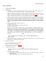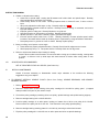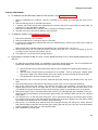
1
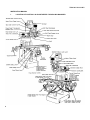
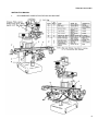
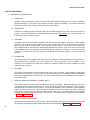
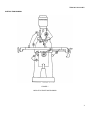
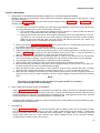
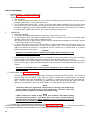
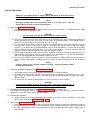
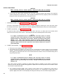
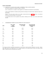
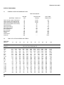
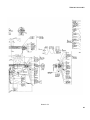
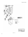
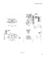
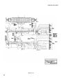
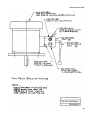
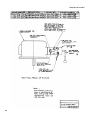
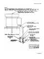
TM 9-3417-213-14&P
TECHNICAL MANUAL
OPERATOR’S, ORGANIZATIONAL, DIRECT SUPPORT
AND GENERAL SUPPORT MAINTENANCE MANUAL
(INCLUDING REPAIR PARTS LIST)
FOR
MILLING MACHINE, VERTICAL
MODEL 747VS
(WELLS-INDEX CORPORATION)
(NSN 3417-00-764-7993)
HEADQUARTERS, DEPARTMENT OF THE ARMY
JULY 1981
TM 9-3417-213-14&P
Technical Manual
HEADQUARTERS
DEPARTMENT OF THE ARMY
Washington, DC, 10 July 1981
No. 9-3417-213-14&P
OPERATOR'S, ORGANIZATIONAL, DIRECT SUPPORT
AND GENERAL SUPPORT MAINTENANCE MANUAL
(INCLUDING REPAIR PARTS LIST)
FOR
MILLING MACHINE, VERTICAL
MODEL 747VS
(NSN 3417-00-764-7993)
REPORTING ERRORS AND RECOMMENDING IMPROVEMENTS
You can help improve this manual. If you find any mistakes or if you know of a
way to improve the procedures, please let us know. Mail your letter, DA Form 2028
(Recommended Changes to Publications and Blank Forms), or DA Form 2028-2,
located in the back of this manual direct to: Commander, US Army Armament
Materiel Readiness Command, ATTN: DRSAR-MAS, Rock island, IL 61299. A reply
will be furnished direct to you.
NOTE
This manual is published for the purpose of identifying an authorized commercial
manual for the use of the personnel to whom this milling machine is issued.
Manufactured by: Wells-Index Corporation
Div. of Wells Mfg. Corp.
1100 W. Broadway
Three Rivers, MI 49093
Procured under Contract No. DAAA09-75-M-8587
This technical manual is an authentication of the manufacturers' commercial
literature and does not conform with the format and content specified in AR 310-3,
Military Publications. This technical manual does, however, contain available
information that is essential to the operation and maintenance of the equipment.
i
TM 9-3417-213-14 & P
INSTRUCTIONS FOR REQUISITIONING PARTS
NOT IDENTIFIED BY NSN
When requisitioning parts not identified by National Stock Number, it is mandatory that the following information be
furnished the supply officer.
1 - Manufacturer's Federal Supply Code Number - 30456
2 - Manufacturer's Part Number exactly as listed herein.
3 - Nomenclature exactly as listed herein, including dimensions, if necessary.
4 - Manufacturer's Model Number - 747VS
5 - Manufacturer's Serial Number (End Item)
6 - Any other information such as Type, Frame Number, and Electrical Characteristics, if applicable.
7 - If DD Form 1348 is used, fill in all blocks except 4, 5, 6, and Remarks field in accordance with AR 725-50.
Complete Form as Follows:
(a) In blocks 4, 5, 6, list manufacturer's Federal Supply Code Number
manufacturer's Part Number for the repair part.
30456
(b) Complete Remarks field as follows:
Noun:
(nomenclature of repair part)
For:
NSN:
3417-00-764-7993
Manufacturer:
Wells-Index Corp.
Div. of Wells Mfg. Corp.
1100 W. Broadway
Model:
747VS
Three Rivers, MI 49093
Serial:
(of end item)
Any other pertinent information such as Frame Number, Type. Dimensions, etc.
ii
followed by a colon and
TM 9-3417-213-14 & P
1
TM 9-3417-213-14 & P
SPECIFICATIONS
TABLE
Overall size ....................................................... 9"x 46"
T-slots: number and size............................... Three 5/8”
Distance between T-slots .................................... 2 1/4"
Handwheel dial graduations................................... .001"
TRAVELS
Longitudinal ............................................................ 32"
Cross ..................................................................... 12"
Vertical (knee) ........................................................ 17"
Quill ................................................................... 5 1/4"
Overarm.................................................................. 21"
THROAT DIMENSIONS
Canter of spindle to column face .2 3/4" min., 23 3/4" max.
Center of table to column face
(Standard) ................................... 5" min., 15" max.
(Optional) .................................................17" max.
Spindle nose to top of table ................. 0" min., 17" max.
HEAD, QUILL, SPINDLE AND TURRET
Turret and overarm, around turret ............... rotation 360°
Head tilt (front to back) ...................................45°-0-45°
Head tilt (side to side) ................................. 180°-0-180°
Spindle taper
(Standard) ..................................... R-8 or #9 B & S
(Optional) .......................... #30 MMT- quick change
Spindle speeds
(Standard) - in back gear ............... 75,125, 210, 355
In direct drive................... 600, 1000,1675, 2850 rpm
(Optional) - in back gear .............. variable 50 to 525
In direct drive ....................................... 400 to 4200
Reverse ................................................................. Yes
Quill outside diameter .......................................... 3 3/8"
Quill feeds - (3)
Per spindle revolution................. .0015", .003", .006"
MOTORS
Spindle (single speed) ......................................... 1 h.p.
Table Feed (optional) ........................................1/4 h.p.
SHIPPING WEIGHT (approx.) ......................... 2100 Ibs.
2
TM 9-3417-213-14 & P
INSTRUCTION MANUAL &
PARTS LIST
HORIZONTAL & VERTICAL MILLING MACHINES
Machine Serial No.
CONTENTS
INSTRUCTION MANUAL
I.
II.
III.
IV.
V.
VI.
VII.
VIII.
IX.
X.
XI.
XII.
Machine Controls ..................................................................................................................Page 4
Lubrication ............................................................................................................................Page 5
Preliminary Information ..........................................................................................................Page 6
Adjustments .........................................................................................................................Page 8
Operation .............................................................................................................................Page 10
Preventive Maintenance ........................................................................................................Page 13
Trouble Shooting ..................................................................................................................Page 13
Spare Parts Recommended ...................................................................................................Page 14
Special Maintenance .............................................................................................................Page 14
Speeds For End Mills ............................................................................................................Page 19
General Speed Recommendations .........................................................................................Page 20
Table of Cutting Speeds & Feeds ...........................................................................................Page 20
MACHINE ASSEMBLIES
B900-011
B900-012
100-002-032
100-003-360
101-112-101
101-180-101
101-180-207
101-180-209
101-212-202
101-212-204
101-218-201
101-346-101
101-436-101
101-670-101
101-671-101
101-672-101
Floor Plan - Models 747-847
Floor Plan - Model 860
Wiring Diagram
Wiring Diagram
Base Ass'ys. - 747 & 847
860 Col. & O'Arm Ass'y.
Spindle Housing Ass'y - 860
Sand. Ass'y V.S.D. all Gear-860
Head & Quill Ass'y.
Sandwich Ass'y.
Var. Speed Sandwich Ass'y.
Knee Ass'y
Table & Saddle Ass'y.
1 H.P. 3 PH. Motor
2 H.P. Motor
1 H.P. 1 PH. Motor
3
TM 9-3417-213-14 & P
INSTRUCTION MANUAL
I.
4
LOCATION OF CONTROLS & ADJUSTMENTS FOR MILLING MACHINES
TM 9-3417-213-14 & P
INSTRUCTION MANUAL
II.
RECOMMENDED LUBRICATION FOR MILLING MACHINE
5
TM 9-3417-213-14 & P
INSTRUCTION MANUAL
III. PRELIMINARY INFORMATION
A. UNCRATING:
Carefully remove the protective crating and skid so that the machine and parts are not marred, scratched or
otherwise damaged. in the event of any damage in transit, report it immediately. The machine should be
lifted from the base of the crate by placing a sling under the overarm.
B. SHORTAGES:
Inspect the complete shipment carefully against the itemized packing list to make sure that all items are
present. In the event shortages are noticed they should be reported immediately, with a clear indication as
to which parts have not been received.
C. CLEANING:
Thoroughly clean the rust preventive materials from the machine with gasoline, kerosene, or other suitable
solvents. Do not move the table, saddle, knee or other moving parts until all of the sliding way surfaces
have been well cleaned and lubricated. After cleaning carefully move to. a limit stop in one direction the
table, saddle and knee, and clean and lubricate the exposed way surfaces. Then move each of these units
to the opposite limit stop and similarly clean and lubricate the exposed way surfaces. Loosen the four bolts
to unlock the overarm and move this forward and backward to the extreme position in order to clean and
lubricate.
D. FOUNDATION:
For best performance it is important that the machine be placed on a solid foundation and that it be level. A
solid concrete floor is desirable, but a firm wooden floor, free from vibration, may be suitable. If the
machine is to be located on an upper floor or balcony it should be placed as close as possible to a strong
supporting pillar or column.
E. LEVELING:
The machine is provided with four bolt holes one at each corner of the base. Steel wedges or steel plates
should be used for leveling. A good machinist's level should be used in the leveling process and the bubble
should have adequate time to come to rest. The level should be placed both lengthwise and crosswise on
the machine table.
F. VERTICAL HEAD ON OVERARM: (EXPORT ONLY)
The is positioned on the overarm with the spindle up and the motor down. Before operating the machine it
is necessary that the head be returned to its normal operating position by loosening the 4-5/8 hexagonal
nuts located at the head end of the overarm. It will then be possible to tilt the head into normal operating
position by using a crank on the 1 in stud located on the right side of the front end of the overarm. Because
of the heavy overhung weight involved,.the tilting of the head back to its normal position will be greatly
facilitated i fa second person can help push it into position. The head may then be trammed in as described
in Section V, paragraph H-I.
G. VERTICAL HEAD ON OVERARM
The vertical head is tilted back on the overarm. Before operating the machine it is necessary that the head
be returned to its normal operating position and trammed in as described in Section V, Paragraph H-I.
6
TM 9-3417-213-14 & P
INSTRUCTION MANUAL
FIGURE 1
INDICATOR POSITION DRAWING
7
TM 9-3417-213-14 & P
INSTRUCTION MANUAL
IV. ADJUSTMENTS
A. PROPER GIB ADJUSTMENT PROCEDURE MUST BE DONE AFTER 40-HOURS ON NEW MILLS
Each 700 and 800 series of mills have three gibs. One at front dovetail of table; one on left dovetail of
saddle; one on left dovetail of knee.
Each gib is supplied with two lock or adjustment screws.
The table gib has a lock screw on the right front of the saddle and the adjusting screw is on the left front of
the saddle.
The saddle gib lock screw is at the rear of saddle on the left side, the adjusting screw is at the front of the
saddle on the left side.
The knee gib lock screw is on the bottom of the knee on the left side, the adjusting screw is on the top on
the left side.
Loosen the table gib lock screw several turns and tighten the adjusting screw until you feel the gib pressing
against table dovetail, then tighten the lock screw, Never get this lock screw too tight as it will distort the gib.
Run the table back and forth and check for drag.
Repeat this adjustment for the saddle and the knee gib.
Now to check the gibs with an indicator, the following checks must be made: (See Figure 1 for reference)
1. With indicator mounted as in Position 3, the table gib can be tested for shake by pulling back and
forth on the end of the table.
Anything over .0015 is too much, also the table should snap back to "0" each time.
2. To check the saddle gib, the indicator should be mounted as in Position 7 and the same tolerance
should exit here.
3. The knee gib will be checked as in Position 5 by grasping the end of the table and lifting up and
pushing down. Deflection here should not be more than .0003.
Now as a final check use Position 2 and run the table to its extreme right and left position.
The indicator runout should not be more than .0015.
B. QUILL FEED CLUTCH:
This clutch has been tested by drilling a 5/8 dia. drill in mild steel. After testing, the clutch is then adjusted
to a minimum setting. If in operation, larger pressures are developed which cause the clutch to ratchet, it
may be well to readjust the clutch using the steps below. If still larger pressures are needed after
readjusting, you may assist the Quill Feed by applying a downward pressure on the hand feed lever.
PROCEDURE FOR ADJUSTING THE CLUTCH
Reference drawing 101-212-202, Section K-K
1. in the rear of the head between the head and the adapter is a hex nut (100-002-906) with a No.10-24
x 1/2 socket head cap screw for a lock.
a. First unscrew this lock screw until it is freely rotated with the fingers.
2. The minimum clutch tension is the position shown in the drawing. If more tension is desired, rotate
he hex nut (100-002-906) up to 180° from its present position, and relock the No. 10-24 socket head
screw.
3. It may also be desirable to adjust the travel of the clutch plunger:
a. This is done by means of the 1/4 20 x 3/4 socket set screw immediately behind the (100-004-543)
feed cam housing as shown in Section F-F.
b. With the clutch disengaged tighten the set screw until a little roughness can be felt when moving
the quill down by means of the hand lever.
8
TM 9-3417-213-14 & P
INSTRUCTION MANUAL
C. PROCEDURE FOR REMOVING AND REPLACING QUILL COUNTER-BALANCE SPRING
(Extreme caution should be exercised in this operation and instructions followed closely as this spring is 11 foot
long when unwound.)
Using drawing (101-212-202) which is the head and quill assembly refer to section K-K and (101-112-101) base
assembly refer to B-B and view Z:
1. The safest way to perform this operation is to first drop the quill assembly (101-212-307) down until the rack
on the quill clears the pinion on the (100-004-546) cross shaft.
a. This is performed by first removing the drawbar and the (100-027-771) vernier holder and then the
two 5/16-18 x 7/8 socket heads in the (100-002-917) quill block.
b. Holding the left hand on the bottom of the spindle and the right hand on the hand feed lever (101-212312) slowly run the quill down out of the head casting by rotating the hand lever counter-clockwise
(When the quill rack clears the pinion, the quill is free to fall and the hand lever may unwind very
rapidly causing injury if not held tight and unwound slowly.)
2. Referring to drawing (101-112-101) section B-B remove the two 7/16-14 x 2 socket head screws which hold
the (100-007-100) plate to the (100-009-202) adapter.
3. Remove the three 5/8 hex nuts which bolt the (100-007-100) plate to the head casting.
4. Grasp the (100-007-100) in such a way that the thumb can be pressed against the (100-002-910) cover
shown in section K-K and gently pull the entire assembly away from the head. It may be necessary to
gently tap this plate with a soft hammer to break the initial contact with the head.
5. After this assembly is removed from the head and layed on a bench, very carefully lift the (100-002-910)
cover off the spring by holding it in place and pulling the (100-002-909) coupling away from the assembly.
6. Very carefully pry the shield (100-002-911) away from the spring assembly.
7. Now the spring can be pushed out of the (100-004-542) housing from the bottom of the inside.
8. When the new spring is installed, it will have to be in the right direction so that the hook on the spring is in
the same direction as the slot in the (100-002-909) coupling.
9. When the three 5/8 nuts are put back on, they should be snug until the (100-007-100) plate is securely
fastened to the (100-009-202) adapter by means of the two 7/16-14 x 1-1/2" socket head cap screws.
10. When the quill is replaced in the head, the counter-balance spring must be wound up tight by moving the
hand lever (101-212-312) counter clockwise to its limit and then engage the quill rack with the cross shaft
pinion.
NOTE
This spring is not intended to return the quill to its upper position, it is merely to
cancel out the weight of the quill assembly.
D. QUILL FEED TRIPS & DEAD STOP ADJUSTMENT:
Refer to drawing #101-212-202. The Vertical Mill is provided with a means for setting an adjustable automatic
feed trip device for the downward movement of the quill. Feed trip rod #100-002-961 actuates feed trip plunger
#100-002-958 through feed trip arm #100-002-952 to disengage clutch. Disengagement occurs when quill feed
trip key #100-002-917 contacts quick shift dial sleeve nut #100-002-763.
Downward feed adjustment is made by loosening knurled thumb screw #056-033-152 and repositioning quick
shift dial sleeve nut #100-002-763.
E. DRIVE BELTS:
Refer to drawing #101-212-204. To provide the necessary slack for shifting of belt it is only necessary to loosen
the motor clamp handle #100-002-955 (on right rear of pulley guard) and move motor forward. Increase belt
tension by moving motor back and tightening motor clamp handle. To replace worn or broken belt remove 6
socket head screws from top of #111-212-002 drive pulley cartridge and lift off #111-212-002 cartridge,
(2 tapped holes provided for jack screw if req'd.)
9
TM 9-3417-213-14 & P
INSTRUCTION MANUAL
F. SPINDLE BRAKE - VARIABLE SPEED HEAD
Refer To Drawing #101-218-201 (Sect. AA).
TO ADJUST THE SPINDLE BRAKE:
1. Start the spindle.
2. Turn 1/4-20 set screw #010-102-576 in until you hear the brake rubbing, then back the set screw out just
enough to stop rubbing. Lock in place with jam nut.
3. Turn complete brake handle ass'y. so that 111-218-204 shaft rotates clockwise until you hear the brake
rubbing, then turn counter clockwise just enough to stop rubbing & allow the handle to be hanging down. If
the handle is pointing up when properly adjusted, knock the 3/16 dia. spiral, tin #010-454-512 out, reverse
the handle 180 0 & replace the 3/16 dia. pin, so that the handle is hanging down.
V.
OPERATION
A. VERTICAL SPINDLE
1. The spindle Start Stop Reverse Control is located at the upper left on the motor.
2. On the standard V-belt drive head the spindle brake lever is located at the top left of the pulley guard
assembly. Move it to the left or right to engage the brake.
After moving to the left or right this lever may be raised to maintain brake engagement and hold the spindle
in a fixed radial position for tool changing.
3. On the variable speed drive head the spindle brake is located at the bottom left of the pulley guard. It is
engaged by pulling the control lever out away from the pulley guard. This camming action actuates the
caliper type brake and will hold it in engagement until the control lever is returned back to its normal
position flush with the pulley guard.
CAUTION
Always be sure spindle brake is completely disengaged before attempting to start
spindle rotation in either direction.
4. Spindle speeds on the standard V-belt drive are changed by changing the position of the V-belt connecting
the motor pulley to the spindle pulley and by shifting the back gear lever (high, low, or neutral).
5. Spindle speeds on the variable speed drive head are even more readily changed by moving the control
lever from left to right or right to left with the spindle motor running and by shifting the back gear (high low or
neutral).
CAUTION
Always be sure spindle motor is running before attempting to move variable speed
adjustment lever.
B. BACK GEAR (See Drawing #101-212-204)
The back gear lever (shift lever #100-002-900) is located on the upper left side of the head. The lever has 3
positions; high, low, and neutral. in the high (out) position, spindle drive is geared directly from spindle
pulley to spindles (dog clutch #100-002991 is in up position, in contact with drive cone pulley hub #100-002999). in the low (in) position, spindle drive is geared through back gear #100-002-985 (dog clutch #100002-991 is in down position, back gear #100-002-991 is in mesh with back gear #100-004-557).
NOTE
Because of back gear construction, when machine is running in low speed range,
spindle rotation is opposite to that of high speed range. Therefore, forward on
reversing switch becomes reverse when in low speed range.
1
NOTE
When shifting from neutral to high or low, turn spindle by hand while pushing
back gear lever into position. This allows gears to line up in low speed and dog
clutch to line up in high speed. When shifting into high, it is imperative to have the
spindle brake in the brake on position.
2
C. POWER FEED TRANSMISSION ENGAGEMENT (See Drawing #101-212-202).
The power feed engagement lever #100-002-900 is located directly below the back gear lever. This lever has 2 positions;
in, to engage spindle power feed transmission, and out to disengage spindle power feed transmission.
10
TM 9-3417-213-14 & P
INSTRUCTION MANUAL
CAUTION
Always be sure spindle motor is stopped before attempting to move this lever to
the in or engaged (upper) position.
NOTE
Disengage spindle power feed transmission when it is not being used. This will
stop unnecessary wear on power feed worm gear.
D. QUILL (See Drawing #101-212-202)
1. The quill may be locked in a given vertical location by turning the quill-clamp in a clockwise direction. Lever
is located at bottom of right side of head.
CAUTION
Do not engage quill feed with quill-clamp lever fully tightened.
2. The quill (or spindle) hand feed lever #100-002-107 can be adjusted to any one of six operating positions by
moving outwards (to the right) on the lever hub and rotating to the desired position. The hand feed lever is
held on by a spring plunger and can be pulled off when not in use.
3. Any one of three power feeds (in either an upward or downward direction) may be selected by moving the
feed shift lever, located on right side of head, to the desired feed (.0015", .003" or .006") per spindle
revolution. A neutral position is provided between each of these feed settings. If power feed is not being
used it is wise to place the feed shift lever in one of the neutral positions. It may be somewhat easier to
change the position of the feed selector lever when the spindle is rotating.
4. The fine feed handwheel #100-004-545 is placed in operating condition by locating the feed shift lever in a
neutral position and engaging the power feed engaging lever #100-002-953. The fine feed handwheel is
held on by a spring plunger and can be pulled off when not in use.
5. The knob on the shaft located in the center of the feed handwheel is used to select downfeed (pushed-in
position), neutral (mid-position) or upfeed (pulled-out position) for either the power feed or the handwheel
feed.
NOTE
Positions noted are for clockwise rotation of spindle. Counter clockwise rotation
reverses these positions.
E. VERTICAL SPINDLE DRAWBAR (See Drawing #101-212-202)
Use spindle brake to restrict spindle rotation when tightening or loosening drawbar.
1. To install collet or tool holder in spindle - first, remove drawbar by pulling it out of spindle from top. Then,
place collet or tool holder into spindle. Put drawbar back into spindle and tighten into collet or tool holder,
using discretion.
2. To remove tool from spindle--loosen drawbar 3 or 4 turns and tap on end to free tool.
CAUTION
Do not loosen drawbar less than 4 or more than 5 turns when removing tool. If
drawbar is too loose, the threads may be stripped when tapping on end.
F. HORIZONTAL SPINDLE DRAWBAR (See Drawing #101-180-207 (101-180-203 old)
Use spindle brake located at back of machine to restrict spindle rotation when tightening or loosening drawbar.
(Otherwise it .is the same as the Vertical Spindle Drawbar).
G. HORIZONTAL SPINDLE:
1. Spindle direction is set by forward-reverse switch located on left side of column. (Otherwise it is the same
as the Vertical Spindle see paragraph V-A-3 & V-A-5)
H. HEAD: (See Drawing 101-112-101)
1. Tilting of the head in a front to back plane (turret and overarm models) is readily accomplished by loosening
the 3 nuts at the right hand side of the head (around the hand feed lever) and the 3 nuts on the left side of
the head, and applying crank to forward head tilting worm stud #100-002-963, located at bottom rear of
head -left side.
11
TM 9-3417-213-14 & P
INSTRUCTION MANUAL
CAUTION
When returning head to vertical position, sweep the table with an indicator
attached to spindle to make sure head is square to table.
2. To tilt head from side to side, loosen the hex nuts which clamp the head to the overarm or the machine
column (whichever the case may be). Then tilt head the desired amount by applying crank to the sidewise
tilting worm stud at the right to the rear of the spindle head.
CAUTION
When returning head to vertical position, sweep the table with an indicator
attached to spindle to make sure head is square to table.
I. OVERARM OR RAM: (See Drawing 101-112-101 & 101-180-101)
The back to front position of the head and overarm is readily changed by loosening the 4 hex nuts which clamp
the overarm to the turret. Apply a crank to the overarm adjustment shaft extension and move to desired position.
J. TURRET (Vertical Mill) : (See Drawing 101-112-101)
To index the entire turret-overarm-head assembly loosen the 4 hex nuts, 2 on either side of the overarm which
clamp the turret to the top of the column. Then swing the turret to the desired position and reclamp.
NOTE
It is highly recommended that all clamping nuts and bolts (turret to column,
overarm to turret, head side-wise tilt and head forward-back tilt) be securely
tightened before any machining cuts are taken. Always check these points before
starting a cut. Also, when returning overarm to normal position, attach an
indicator to the overarm, and slide the overarm in and out, with the indicator riding
against a square, which has been squared to front of table to make sure overarm is
square with table.
K. TURRET (Horizontal Mill) : (See Drawing 101-180-101)
1. The turret can be rotated on the column a full 360°.
2. The locating pins are effective only when the ram is used with the overarm support for the horizontal
spindle. The vertical spindle at this time would be at rear of machine. It may be necessary to tilt the vertical
head slightly for clearance at the rear of the machine when the machine is set for horizontal milling with a
long milling cutter arbor.
NOTE
It is highly recommended that all clamping nuts and bolts (turret to column,
overarm to turret, head side-wise tilt and head forward-back tilt) be securely
tightened before any machining cuts are taken. Always check these points before
starting a cut.
Also, when returning overarm to position for vertical milling, attach an indicator to the overarm, and slide the
overarm in and out, with the indicator sliding against a square which has been squared to front of table to make
sure overarm is square with table.
3. The complete horizontal spindle, turret, overarm & arbor bearing may be positioned 30° either side of
normal horizontal milling position by loosening the four 5/8 hex. hd. screws (two on either side of the
spindle, slightly below the C/L of the spindle) and swing the entire top unit to the desired angular position.
12
TM 9-3417-213-14 & P
INSTRUCTION MANUAL
VI.
PREVENTIVE MAINTENANCE
A. INSPECTIONS:
1. Inspect taper of spindle for cleanliness and freedom from chips of foreign matter. Frequency Each time tool
holder is inserted. Inspection by machine operator. No special equipment required.
2. Inspect and adjust gibs of slide ways. Frequency every 160 hours. More often if looseness is noted by
operator. Inspection and adjustment by machine operator or machine maintenance man. No special
equipment required other than allen wrench. (See gib adjustment instructions item IV-A)
3. Inspect for general cleanliness of machine, paying particular attention to keep dirt and chips from slide
ways. Do not use air to remove such dirt and chips -but wipe off ways or keep them covered. Flood ways
with light oil and work slide movements back and forth to wash out foreign matter. Then re-lubricate
machine according to lubrication instructions. Frequency Constantly, as far as wiping off chips and dirt are
concerned. Every 40 hours ways should be flooded with oil and cleaned as above. No special equipment
required.
4. Inspect drive belts for wear, hard spots at splice, etc.
Frequency Every 40 hours.
Inspection by machine operator or machine maintenance man.
No special equipment required.
5. Inspect to see if vertical head is square with table, by mounting indicator on spindle and sweeping table.
Frequency Every 80 120 hours, or after head has been tilted. Inspection by machine operator or machine
maintenance man. Special equipment required consists of (1) A short accurate arbor to insert in spindle.
(2) A clamp for use in clamping a 6" bar to above arbor in a horizontal position. (3) 6" bar approximately
1/2" in diameter. (4) An accurate dial indicator to clamp to above 6" bar in position so when spindle is
revolved by hand, nib of indicator in contact with table, sweeps table in a full circle and indicates out of
squareness.
NOTE
Table is intentionally left .0005" high in front.
machine is used.
This will gradually decrease as
6. Inspect electrical equipment. Frequency in accordance with standard plant policy. Inspection by machine
maintenance man. No special equipment required.
B. PARTS REPLACEMENT:
None except as indicated by wear or malfunction.
Frequency or replacement only as above.
C. LUBRICATION (See Lubrication Sheet Page 2)
VII.
TROUBLE SHOOTING NOTE
NOTE
Ordinarily trouble will not manifest itself except when actually working with
machine.
1. Slide ways working hard or binding.
a. Cause gibs out of adjustment, either too tight or too loose. In the lattercase causing gib to "wedge".
Remedy Adjust gibs.
b. Cause Dirt in slide ways. Remedy - Wash out slide ways with light oil.
13
TM 9-3417-213-14 & P
INSTRUCTION MANUAL
2. Chatter or vibration when cutting.
a. Cause Dirt in spindle taper, causing bad fit between tool holder shank and spindle taper. Remedy
Clean spindle taper and shank of tool holder.
b. Cause Faulty shank on tool holder. Remedy Replace shank or dress off burrs, if due to nicks or
burrs.
c. Gibs poorly adjusted on slide ways, or dirty. Remedy Adjust as in IV-A.
d. Work improperly clamped to table of machine. Remedy Check for rocking or movement, and correct
by proper clamping.
e. Improper grind on cutting tool. Remedy Replace or re-grind tool.
f. Hard spot at splice of drive belts or worm belts. Remedy Replace belts.
g. Spindle quill worn in quill head. Remedy Tighten quill head lock slightly.
h. Incorrect spindle speed, table feed, or both. Remedy Ordinarily increase spindle speed and/or
increase or decrease feed to break up vibration period. Experiment by using hand feed to feed table.
i. Drive pulleys worn in grooves or loose on shafts. Remedy replace pulleys.
3. Boring or milling out of square or at an angle.
a. Cause Head not properly aligned with table. Remedy Check head for alignment and correct.
b. Work improperly set up; i.e. not square and flat. Remedy Check and re-align work.
4. Failure to hold center distance when locating for boring.
Cause Failure to take back-off tension on lead screw after coming up to indicator reading, causing table
to "creep", or failure to lock up slide ways with same amount of tension after moving table to new
position.
VIII.
SPARE PARTS RECOMMENDED
SET OF DRIVE BELTS FOR ALL DRIVES; (See Parts List)
IX.
SPECIAL MAINTENANCE
Should it become necessary to disassemble certain major elements of the machine the following
suggestions may prove helpful.
A. TO REMOVE VERTICAL SPINDLE PULLEY (Drive Cone Pulley), SPINDLE BEARINGS; AND SPINDLE
BEARING SUPPORT:
1. Refer to drawing #101-212-204
2. Remove 6 socket head screws holding drive pulley cartridge #111-212-002 to pulley guard.
holes provided in this part for jack screws if req'd.
(2 tapped
3. Lift out drive pulley cartridge (containing drive cone pulley, spindle bearings and spindle bearing support).
4. Remove cartridge bearing lock nut #100-003-000.
5. Put drive pulley cartridge in an arbor press, locating on bottom face of drive cone pulley #111-212-003.
Drive out drive cone pulley hub #111-212-201. This frees drive cone pulley (spindle pulley).
6. Remove cartridge bearing retaining plate #111-212-004 by removing 4 socket head screws.
7. Flip drive pulley cartridge #111-212-002 over on arbor press and drive out spindle bearings.
14
TM 9-3417-213-14 & P
INSTRUCTION MANUAL
B. TO REMOVE MILLING MACHINE TABLE & LEAD SCREW. (See Drawing #101-436-101)
1. Remove handwheels #111-438-001, dials #111-346-008 & end plates #111-436-005 from each end of
table.
2. Remove retaining cap #111-436-006 from left end.
3. If machine has a table power feed, disassemble by removing the bronze gear inside the power feed, (4)
screws & R.H. end plate #B111-436-005.
4. Disconnect end brackets #111-436-003 & #111-436-004 by removing 4 screws.
5. The table can now be removed by sliding in either direction.
C. TO REMOVE SADDLE (See Drawing #101-346-101)
1. First remove the table, as in "B" above.
2. Remove handwheel #111-438-001 & dial #111-346-008.
3. If machine has independent saddle power feed unit, disassemble by removing the bronze gear inside the
power feed & 4 screws.
Remove plate #111-346-003 replace the handwheel & turn until lead screw is free of nut.
4. Remove lead screw nut #111-436-012 shown on drawing #101-436-101. It may be necessary to pry the
nut loose from two roll pins which position the nut.
5. The saddle can now be removed by sliding forward.
D. PROCEDURE FOR REPLACING OIL SEAL in BACK GEAR HOUSING OF ALL GEAR HEAD MODELS 823 and
IRD-125 1
1. To make this job relatively simple, it is advisable to remove the spindle motor first. This is accomplished as
follows after shutting off the power and moving the speed lever to 4200 RPM.
a. Remove the two 3/8 hex cap screws which hold the motor bracket to the pulley guard assembly (111180-303).
b. Slide the motor forward toward the spindle as far as possible. Then by working the variable speed
belt over the edge of the bottom sheave of the motor pulley, the motor will then be free of the belt.
c. The spindle motor can then be lifted off the pulley guard.
2. Now remove the 1/2-13 hex nuts (3) which holds the back gear housing (101-180-305) to the top of the
head.
3. Run the quill all the way to the bottom of its travel by means of the (101-212-312) hand feed lever.
4. Now lift the entire back gear housing (101-180-305) and pulley guard assembly (101-180-303) off the
spindle spline and the top of the head, and lay onto a suitable work bench with the three studs in the
(101180-305) back gear housing at the top and the mounting surface for the spindle motor on the bottom.
5. Remove the eight /h4-20 x 7/8 socket heads which hold the (101-180-305) back gear assembly to the (101180-303) pulley guard assembly and lift the back gear housing (101-180-305) away from the (101-180-303)
pulley guard.
6. This exposes the (111-180-220) drive shaft which can be removed by lifting out of the back gear housing
thus exposing the top side of the (058-010-088) oil seal which can then be tapped out of the casting, being
very careful not to damage the (077-103-003) 2815 INA bearing.
7. Now put the (111-180-220) drive shaft back into the back gear housing and, being very careful, start the
new (058-010-088) oil seal back into the back gear housing with the lip of the inner race of the seal setting
properly against the OD of the (111-180-220) drive shaft.
8. Now, reassemble in reverse order.
15
TM 9-3417-213-14 & P
INSTRUCTION MANUAL
E. PROCEDURE FOR ELIMINATING SHAKE IN QUILL FEED HAND LEVER
Shake in the quill feed is usually caused by shipping vibration. The proper way to eliminate this
is as follows:
1. Shift the speed range into the direct drive or up position on the back gear lever.
2. Run the spindle speed at approximately 1200 RPM with the quill fully retracted into the head casting.
3. Loosen the three 1/2" nuts which hold the back gear housing (100-009-204) to the top of the head, thus
allowing the back gear and pulley guard assembly to "float".
4. Then by tightening the 1/2" nuts, preferably the front one first, the back gear assembly will tend to center
itself. (NOTE A little experimenting may have to be done if tightening the front nut first does not eliminate
the shake.)
5. in rare cases, the pulley guard housing could have been shaken out of line from the (100-009-204) back
gear housing.
In this case, the eight 1/4-20 x 7/8 socket heads which hold these two assemblies together will have to be
loosened slightly and the unit allowed to center itself as explained in Step 4.
F. PROCEDURE FOR CHANGING R-8 PIN 745, 747, 756,757, 847, 856, 857, 760,860, and 887
1. Loosen 10/32 socket set screw on the bottom and read of the quill body.
2. Unscrew the(100-002-972) or(100-002-977) nut from the end of the quill using a spanner wrench with 5/32
or 3/16 lugs.
3. Pull or pry the (100-002-974) brass retainer down over the taper end of the spindle thus exposing the head
of the R-8 pin which can then be pulled out of the spindle.
4. Replace the pin and reassemble in reverse order.
G. PROCEDURE FOR CHANGING HEADS 745,747,845,847,760,860,887
CAUTION
Before loosening all four 5/8" nuts on front of overarm, have a sling on the head to
prevent falling.
1. Remove motor from pulley guard for VSD, see Step 5.
2. Remove (010-222-378) tilt shaft which will free up the (056-008-053) Boston worm gear and allow it to fall
free of the overarm.
4. Remove three of the 5/8 hex nuts which hold the 100-009-202) adaptor to the front of the overarm.
5. Then after a hoist or sling is attached around the head or pulley guard, the remaining 5/8 nut may be
loosened. (Caution: The head is then free to fall to either side.)
6. Then pull straight out on the head assembly to clear the (100-004-569) tilt gear and the (100002-904) T
bolts.
7. Reassemble in reverse order.
H. STEPS TO TAKE TO CHANGE MOTORS ON VARIABLE SPEED HEADS
1.
2.
3.
4
5.
6.
16
Speed shift lever set at 4200 RPM.
Remove two 3/8 16 x 1-1/4 hex head cap screws which hold the motor to the pulley guard.
Slide motor as far as possible toward the spindle and work the belt over the motor pulley.
Remove motor from the pulley guard housing.
Remove pulley from defective motor and reassemble in reverse order.
It may be necessary to force the motor pulley flanges apart a little to facilitate slipping the belt over the
pulley.
TM 9-3417-213-14 & P
INSTRUCTION MANUAL
I. INSTRUCTIONS FOR CHANGING SPINDLES IN THE FOLLOWING MODELS 745. 747. 756, 757, 845, 847,
856, 857,760, 860, and 887.
1.
2.
3.
4.
5.
6.
7.
8.
9.
10.
11.
12.
13.
14.
Remove drawbar.
Drop knee and move saddle to rear so as to provide clearance for quill removal.
Remove (100-027-771) adjustable vernier blade holder.
Remove two 5/16-18 x 7/8 socket head cap screws in (100-002-917) quill feed trip key and remove key.
Put right hand on (101 -212-312) spindle feed handle arm and left hand on the bottom of the quill, and by
moving the (101-212-312) handle in a counter clockwise direction, run the quill down until the rack on the
quill clears the pinion on the cross shaft.
When this happens, the (101-212-312) hand lever will unwind very rapidly. If released, it could cause
injury. So it must be unwound slowly.
Let the quill slide down out of the head casting and put it in a vise, being sure to use brass or lead jaws in
the vise.
Release the locking ear of the W-07 lock washer in the N -07 locknut or snap ring in the top of the quill and
remove nut from the spindle. (See Paragraph 11)
Remove (100-002-972) front bearing retainer from quill after first releasing the 10/32 socket set screw in the
lower rear of the quill. (NOTE: in the case of #30 MMT, the number is 100002-977.)
Remove quill from the vise and strike spline or upper end of spindle against a solid piece of wood laying
against a solid surface, such as the floor. The spindle and the two lower spindle bearings and spacers will
then come out of the quill.
Replace new spindle and assembly in reverse order making very sure that the N-07 locknut is tight enough
so as to put tension on the 2968 spacer on serial number before approximately 17105 on R8 spindles and
approximately 17360 on #9 B & S and #30 MMT spindles. After this serial number make sure the locknut is
tight against the bearing.
When putting the quill back into the head casting, first start the quill into the bore of the casting by gentle
pressure and care (do not force).
Line up the spline of the spindle with the spline of the (100-004-576) drive hub by turning the spindle after it
goes up against the bottom of the (100-004-576) hub.
Next, wind the 101-212-312 counter clockwise to the end of its spring tension and push quill up until the
rack of the quill engages the pinion of the cross shaft and use (101-212-312) hand lever to raise quill up to
the top of its travel.
J. PROCEDURE FOR FREEING UP BACK GEAR TO DIRECT DRIVE 745, 756, 760, 845, 856, 747, 757, 860, 847,
and 857
This particular problem is usually caused by the (111-218-001) pulley guard being jolted out of line during
shipment and can usually be remedied as follows:
1. Shift the back gear lever into the direct drive or upper range and set the speed at about 1500 RPM.
2. Loosen the eight 1/4-20 x 7/8 socket head cap screws which hold the (111-218-001) belt guard to the (111218-212) assembly)
3. Turn on the spindle motor, move the (111-218-001) belt guard a very slight distance in several directions.
The dowel pin hole in the front of the pulley guard can be used with 1/4" allen wrench to move the pulley
guard back and forth.
4. The pulley guard will actually tend to center itself if reasonable care is exercised when retightening the eight
socket heads that hold the belt guard to the back gear housing.
17
TM 9-3417-213-14 & P
INSTRUCTION MANUAL
K. PROCEDURE FOR ELIMINATING CREEP IN VSD SHIFTER
I. Referring to drawing (101-218-201) variable speed drive sandwich assembly, lower right hand drawing at
the extreme top of the head you will notice four 10/32 x 7/8 button head screws which hold the (111-218002) shift lever assembly to the (111-218-003) cam housing.
These four screws keep enough tension on the 1056-004-451) cup washers to provide the proper friction
between the shift lever and the housing to prevent creeping.
This creeping is easily remedied by tightening these four button head screws.
L. METHOD OF CHANGING PRESENT SPINDLE FOR OLDER TYPES WITH 2968, 2969, AND 2970 SPACERS
1. Remove N-07 lock nut from top of spindle.
2. Loosen 10/32 lock screw from bottom of quill.
3. Remove 2972 quill nut by turning counter clockwise.
4. Tap splined end of spindle on block of hard wood and spindle and two lower bearings will come out.
5. Discard spacer 2968.
6. Put 200-039 spacer on splined end of spindle against the thrust bearings of new spindle.
7. Press entire assembly in quill and install quill nut.
8. Install snap ring on top of spindle.
9. If old spindle bearings are used, discard spacers 2969 and 2970.
M. PROCEDURE FOR CHANGING BRAKE SHOES ON VARIABLE SPEED HEAD ASSEMBLY
1. With spindle motor running shift spindle speed to highest RPM then remove spindle motor as described in
paragraph "H".
2. Referring to drawing 101-218-201 in the service manual remove the 111-218-002 speed shift lever by
removing the four (4) socket head cap screws which hold it against the 111-218-205 ring.
3. Remove the six (6) 1/4 20 x 3/4 socket heads which hold the 111-218-003 cam housing to the pulley guard
and remove housing from pulley guard.
4. Now by reaching through the holes in the sides of the pulley guard, the lower pulley sleeve can be worked
up out of the pulley guard casting, thus exposing the brake shoes.
5. Now the 3/8 x 3-1/4 roll pins can be driven in to clear the brake shoes. (Note: The pins must be driven all
the way to clear the pulley guard casting and fall free.)
6. Unscrew the 111-218-204 brake pull rod and remove old shoes.
7. Reassemble in reverse order making sure the 056-009-636 cog belt is around the drive hub. This is made
simpler if the cog hub is slowly rotated while being pushed or tapped down into its proper position.
8. After reassembly is completed, the shoes can be properly adjusted by first tightening the 1/4 20 x 1-1/4
socket set screw above the brake handle until the shoe makes contact with the outer race of the pulley and
then backing off to just clear. Then the 111-218-004 brake pull rod should be turned clock wise until
contact is made with the inner pulley race and then backed off to clear.
18
TM 9-3417-213-14 & P
INSTRUCTION MANUAL
N. PROPER WAY TO CHECK FOR POSSIBLE LOOSENESS OF QUILL IN HEAD CASTING
AND FOR LOOSENESS OF SPINDLE IN QUILL HOUSING
Once in a while there is a complaint on what appears to be looseness in the head and or quill assembly.
In 99% of these cases this is caused by loose gibs and has nothing to do with the fit of the spindle and quill in the
head casting.
However, in the event that a check is to be made, it should be done as in Figure 1, Position 1 & 9 with the
indicator base mounted solidly on the head itself.
If a reasonable amount of force is applied to the, spindle, a reading of up to .0005 is not out of line, with the Quill
retracted.
X.
RECOMMENDED SPEEDS FOR HIGH SPEED FAST SPIRAL END MILLS:
SIZE
TOOL STEEL
AND
FORGINGS
MACHINE STEEL
C.R. STEEL
CAST IRON AND
FREE CUTTING
STEEL
1/8"
1675
2850
2850
3/16"
1000
1675
1675
1/4"
1000
1000
1675
5/16"
600
1000
1000
3/8"
600
600
1000
7/16"
600
600
600
1/2"
355
600
600
5/8"
355
355
600
3/4"
355
355
600
7/8"
210
355
355
1"
210
355
355
The foregoing should be regarded as approximate, as many factors control the efficient operation of end mills. Always
keep cutters sharp, and a steady flow of oil or compound directly on the working point will allow much higher cutting
speed. Keep rate of feed consistent with finish required.
19
TM 9-3417-213-14 & P
INSTRUCTION MANUAL
XI.
GENERAL SPEED RECOMMENDATIONS:
FEET PER MINUTE
MATERIAL TO BE CUT
Cast Iron-Soft-(Under 200 Brinnell
Cast Iron-Med.-(200-300 Brinnell)
Cast Iron-Hard-(over 200 Brinnell)
Steel (Chrome Nickel 40-45 Shore)
Steel (Stainless)
Steel (Low Carbon)
Steel (High Carbon)
Bronze (Medium)
Bronze (Hard)
Brass (Hard)
Copper
Duraluminum
Aluminum
XII.
15
20
25
DIAMETER,
INCHES
20
ROUGH AND
FINISH
70
55
40
30
60
80
40
90
65
100
150
400
600
LIGHT AND
FINISH CUT
80-90
60-70
50-60
40
80
90
50
120
90
150
200
-----
120
90
70
50
90
140
70
150
130
200
300
600
1000
TABLE OF CUTTING SPEEDS AND FEEDS
FEET PER
MINUTE
1/16"
1/8"
3/16"
1/4"
5/16"
3/8"
7/ 16"
1/2"
5/8"
3/ 4"
7/8"
1"
1-1/8"
1-1/4"
1-3/8"
1-1/2"
1-5/8"
1-3/4"
1-7/8"
2"
ROUGH
CUT
30
40
50
60
70
80
90
100
4278
2139
1426
1070
856
713
611
535
428
357
306
267
238
214
194
178
165
153
143
134
4889
2445
1630
1375
978
815
698
611
489
407
349
306
272
244
222
204
188
175
163
153
5500
2750
1833
1375
1100
917
786
688
550
458
393
344
306
275
250
229
212
196
183
172
6112
3056
2037
1528
1222
1019
873
764
611
509
437
382
340
306
278
255
235
218
204
191
REVOLUTIONS PER MINUTE
917
458
306
229
183
153
131
115
91
76
65
57
50
45
41
38
35
32
30
28
1222
611
407
306
244
204
175
153
122
102
87
76
67
61
55
50
47
43
40
38
1528
764
509
382
306
255
218
191
153
127
109
95
84
76
69
63
58
54
50
47
1833
917
611
458
367
306
262
229
183
153
131
115
102
91
83
76
70
65
61
57
2445
1222
815
611
489
407
349
306
244
204
175
153
136
122
111
102
94
87
81
76
3056
1528
1019
764
611
509
437
382
306
255
218
191
170
153
139
127
118
109
102
95
3667
1833
1222
917
733
611
524
458
367
306
262
229
204
183
167
153
141
131
122
115
TM 9-3417-213-14 & P
21
TM 9-3417-213-14 & P
22
TM 9-3417-213-14 & P
23
TM 9-3417-213-14 & P
24
TM 9-3417-213-14 & P
Sheet 1 of 2
25
TM 9-3417-213-14 & P
Sheet 2 of 2
26
TM 9-3417-213-14 & P
Sheet 1 of 3
27
TM 9-3417-213-14 & P
Sheet 2 of 3
28
TM 9-3417-213-14 & P
Sheet 3 of 3
29
TM 9-3417-213-14 & P
Sheet 1 of 2
30
TM 9-3417-213-14 & P
Sheet 2 of 2
31
TM 9-3417-213-14 & P
Sheet 1 of 3
32
TM 9-3417-213-14 & P
Sheet 2 of 3
33
TM 9-3417-213-14 & P
Sheet 3 of 3
34
TM 9-3417-213-14 & P
Sheet 1 of 3
35
TM 9-3417-213-14 & P
Sheet 2 of 3
36
TM 9-3417-213-14 & P
Sheet 3 of 3
37
TM 9-3417-213-14 & P
Sheet 1 of 3
38
TM 9-3417-213-14 & P
Sheet 2 of 3
39
TM 9-3417-213-14 & P
Sheet 3 of 3
40
TM 9-3417-213-14 & P
Sheet 1 of 3
41
TM 9-3417-213-14 & P
Sheet 2 of 3
42
TM 9-3417-213-14 & P
Sheet 3 of 3
43
TM 9-3417-213-14 & P
Sheet 1 of 3
44
TM 9-3417-213-14 & P
Sheet 2 of 3
45
TM 9-3417-213-14 & P
Sheet 3 of 3
46
TM 9-3417-213-14 & P
Sheet 1 of 2
47
TM 9-3417-213-14 & P
Sheet 2 of 2
48
TM 9-3417-213-14 & P
49
TM 9-3417-213-14 & P
50
TM 9-3417-213-14 & P
51 (52 blank)
TM 9-3417-213-14 & P
By Order of the Secretary of the Army:
Official:
E. C. MEYER
General, United States Army
Chief of Staff
ROBERT M. JOYCE
Brigadier General, United States Army
The Adjutant General
¶ U.S. GOVERNMENT PRINTING OFFICE : 1988 0 - 201-421 (71628)
TM 9-3417-213-14 & P
TM 9-3417-213-14 & P
TM 9-3417-213-14 & P
TM 9-3417-213-14 & P
PIN: 049471-000
This fine document...
Was brought to you by me:
Liberated Manuals -- free army and government manuals
Why do I do it? I am tired of sleazy CD-ROM sellers, who take publicly
available information, slap “watermarks” and other junk on it, and sell it.
Those masters of search engine manipulation make sure that their sites that
sell free information, come up first in search engines. They did not create it...
They did not even scan it... Why should they get your money? Why are not
letting you give those free manuals to your friends?
I am setting this document FREE. This document was made by the US
Government and is NOT protected by Copyright. Feel free to share,
republish, sell and so on.
I am not asking you for donations, fees or handouts. If you can, please
provide a link to liberatedmanuals.com, so that free manuals come up first in
search engines:
<A HREF=http://www.liberatedmanuals.com/>Free Military and Government Manuals</A>
– Sincerely
Igor Chudov
http://igor.chudov.com/