1
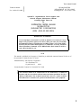
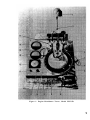
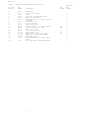
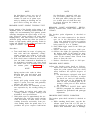
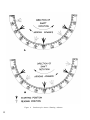
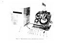
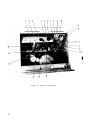
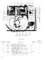
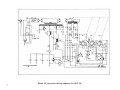
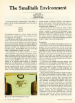
TM 9-4910-622-14&P
TECHNICAL MANUAL
OPERATOR’S, ORGANIZATIONAL, DIRECT SUPPORT
AND GENERAL SUPPORT MAINTENANCE MANUAL
INCLUDING REPAIR PARTS LIST
FOR
DISTRIBUTOR TESTER, ENGINE
MODEL PDT-5D
(SUN ELECTRIC CORPORATION)
(NSN 4910-00-392-2939)
HEADQUARTERS,
DEPARTMENT
OF
THE
ARMY
DECEMBER 1980
TM 9-4910-622-14&P
WARNING
This equipment detrimental to communications, do not operate within 100 feet of operating
communications electronic equipment.
TM 9-4910-622-14&P
Technical Manual
HEADQUARTERS
DEPARTMENT OF THE ARMY
Washington, DC, 29 December 1980
No. 9-4910-622-14&P
Operator’s, Organizational, Direct Support and
General Support Maintenance Manual
Including Repair Parts List
For
DISTRIBUTOR TESTER, ENGINE
MODEL PDT-5D
(SUN ELECTRIC CORPORATION)
(NSN 4910-00-392-2939)
REPORTING OF ERRORS
You can help improve the manual. If you find any mistakes or if you know of a way to
improve the procedures, please let us know. Mail your letter, DA Form 2028
(Recommended Changes to Publications and Blank Forms), or DA Form 2028-2
located in the back of this manual direct to: Commander, US Army Armament
Materiel Readiness Command, ATTN: DRSAR-MAS, Rock Island, IL 61299. A
reply will be furnished to you.
NOTE
This manual is published for the purpose of identifying an authorized commercial manual for the use of
the personnel to whom the tester is issued.
Manufactured by: Sun Electric Corporation
3011 East Route 176
60014
Crystal Lake, IL
Procured under Contract No. DAAA09-76-C-6149
This technical manual is an authentication of the manufacturer’s commercial
literature and does not conform with the format and content specified in AR 310-3,
Military Publications. This technical manual does, however, contain available
information that is essential to the operation and maintenance of the equipment.
TM 9-4910-622-14&P
INSTRUCTIONS FOR REQUISITIONING PARTS
NOT IDENTIFIED BY NSN
When requisitioning parts not identified by National Stock Number, it is mandatory that the following
information be furnished by the supply officer.
1 - Manufacturer’s Federal Supply Code Number - 40067
2 - Manufacturer’s Part Number exactly as listed herein.
3 - Nomenclature exactly as listed herein, including dimensions, if necessary.
4 - Manufacturer’s Model Number - PDT-5D
5 - Manufacturer’s Serial Number (End Item)
6 - Any other information such as Type, Frame Number, and Electrical Characteristics, if
applicable.
7 - If DD Form 1348 is used, fill in all blocks except 4, 5, 6, and Remarks field in accordance
with AR 725-50.
Complete Form as Follows:
(a)
In blocks 4, 5, 6, list manufacturer’s Federal Supply Code Number followed by
a colon and manufacturer’s Part Number for the repair part.
(b)
Complete Remarks field as follows:
Noun: (nomenclature of repair part)
For: NSN: 4910-00-392-2939
Manufacturer: Sun Electric Corporation
Model: PDT-5D
Serial:
Any other pertinent information such as frame number, type, dimensions, etc.
ii
TABLE OF CONTENTS
Page
Subject
Introduction . . . . . . . . . . . . . . . . . . . . . . . . . . . . . . . . .
1
Description . . . . . . . . . . . . . . . . . . . . . . . . . . . . . . . . .
1
Operation . . . . . . . . . . . . . . . . . . . . . . . . . . . . . . . . . . .
1
Instruments and Controls . . . . . . . . . . . . . . . . . . . . . . . .
1
Distributor Point Dwell . . . . . . . . . . . . . . . . . . . . . . . . .
3
Contact Point Gap and Dwell . . . . . . . . . . . . . . . . . . . . . . .
3
Maintenance of Distributors . . . . . . . . . . . . . . . . . . . . . .
3
Adapter for Testing 24 Volt Waterproofed Distributor . . . . .
3
Distributor Visual Inspection . . . . . . . . . . . . . . . . . . . . . .
5
Distributor Mounting . . . . . . . . . . . . . . . . . . . . . . . . . . .
5
Distributor Resistance Test . . . . . . . . . . . . . . . . . . . . . . .
5
Breaker Point Spring Tension Test . . . . . . . . . . . . . . . . . . .
7
Breaker Point Alignment, Dwell, Dwell Variation and
Cam Lobe Accuracy . . . . . . . . . . . . . . . . . . . . . . . . . . . .
7
Breaker Point Dwell . . . . . . . . . . . . . . . . . . . . . . . . . . .
7
Breaker Point Dwell Variation . . . . . . . . . . . . . . . . . . . . .
7
Cam Lobe Accuracy . . . . . . . . . . . . . . . . . . . . . . . . . . . .
9
Mechanical Advance Test . . . . . . . . . . . . . . . . . . . . . . . .
9
Vacuum Chamber Diaphragm Test. . . . . . . . . . . . . . . . . . .
9
Vacuum Controlled Breaker Plate Test . . . . . . . . . . . . . . .
9
Vacuum Spark Advance Test . . . . . . . . . . . . . . . . . . . . . . .
10
Breaker Plate Spring Tension Test for Delco-Remy
Center-Bearing Breaker Plate . . . . . . . . . . . . . . . . . . . . .
Single Vacuum Chamber Loadomatic Distributors. . . . . . . . .
10
Vacuum Chamber Diaphragm Test . . . . . . . . . . . . . .
11
Breaker Plate Test . . . . . . . . . . . . . . . . . . . . . . . .
11
Dual Vacuum Chamber Loadomatic Distributors . . . . . . . . .
11
Vacuum Chamber Diaphragm Test . . . . . . . . . . . . . .
12
Breaker Plate Test . . . . . . . . . . . . . . . . . . . . . . . .
12
Advance Test . . . . .. . . . . . . . . . . . . . . . .
12
Transmission and Over-Drive Governor Test . . . . . . . . . .
12
Governor Test . . . . . . . . . . . . . . . . .
13
Holley Governor Test . . . . . . . . . . . . . . . . . . . . . . . . . . .
13
10
iii
LIST OF ILLUSTRATIONS
Figure No.
Page
Title of Illustration
1
Engine
2
Dwell
3
Waterproof Distributor with Tachometer
Connector Installed . . . . . . . . . . . . . . . . . . . . . .
4
4
Dwell
6
5
Measuring Breaker Arm Spring Tension . . . . . . . 6
6
Stroboscopic
Arrows
7
Loadomatic
Distributor
.
.
.
.
.
8
Loadomatic
Distributor
.
.
.
.
.
9
Delco-Remy
Governor
Distributor
Angle
for
Meter
Tester,
Model
6-Lobe
Cam
Resistance
PDT-5D
.
Readings
Showing
.
.
.
.
.
Advance
.
.
.
Cross-Section
.
.
.
.
.
.
.
.
.
v
.
.
4
.
.
.
.
.
.
.
.
.
.
.
.
.
.
.
.
.
.
11
.
.
.
.
.
.
.
.
11
.
.
12
.
.
.
.
.
.
.
.
8
10
Holley
.
.
.
.
.
.
.
13
11
Engine Distributor Tester, Model PDT-5D
and Accessories . . . . . . . . .
.
.
.
.
.
.
14
12
Interior
Components
.
.
.
.
.
.
.
.
.
.
.
.
.
.
16
13
Interior
Components
.
.
.
.
.
.
.
.
.
.
.
.
.
.
18
14
Flash
Assembly
.
.
.
.
.
.
.
.
.
.
.
.
.
20
15
Electrical
Diagram
.
.
.
.
.
.
.
.
.
.
.
.
21
Governor
Tube
Cross
Wiring
Section
.
.
.
PARTS LISTS
Page
iv
Figure
1
.
.
.
.
.
.
.
.
.
v
Figure
11
.
.
.
.
.
.
.
.
.
14
Figure
12
.
.
.
.
.
.
.
.
.
16
Figure
13
.
.
.
.
.
.
.
.
.
18
Figure
14
.
.
.
.
.
.
.
.
.
20
Figure 1. Engine Distributor Tester, Model PDT-5D
v
PARTS LIST
FIGURE 1. ENGINE DISTRIBUTOR TESTER, MODEL PDT-5D
FIG. AND
INDEX NO.
PART
NUMBER
1-1
-1
-3
-4
-5
-6
848-007
910-027
1185
6002-34
942-2
1493-3
-7
-8
-8
-9
-10
-11
-12
-13
-14
-15
-16
-17
6006-2
5675-1
1938-1
689-48
689-12
1492-6
337-001
767-0118
767-0117
6002-33
1243-504
1493-3
-18
942-2
DESCRIPTION
WORK LIGHT
LIGHT BULB (60-WATT)
KNOB
LEAD ASSY (DISTRIBUTOR GROUND)
KNOB,(FOR DEGREE RING)
KNOB, BAKELITE (13/16" DIA.) VACUUM
REGULATOR
VACUUM HOSE ASSY
LIGHT, INDICATOR
LAMP, GLOW (NE-51)
SWITCH, TOGGLE, 3 P3T (MOTOR SWITCH)
SWITCH, TOGGLE, SPST (RPM)
KNOB (1-1/8" DIA.)
GAGE, VACUUM (0-21")
METER, DWELL (0-50°)
METER, TACH (0-500, 0-2500 RPM)
LEAD ASSY (DISTRIBUTOR TERMINAL)
NAMEPLATE, WARNING
KNOB, BAKELITE (13/16" DIA.) DWELL
METER
KNOB (FOR SPEED CONTROL HAND WHEEL)
VI
REF.
SYMBOL
QUANTITY
PER
TESTER
1
1
1
1
1
1
SW3
SW2
M3
M2
M1
1
1
1
1
1
1
1
1
1
1
1
1
1
INTRODUCTION.
This instruction book contains operation and
maintenance instructions, and a parts list for
the Engine Distributor Tester Model PDT-5D.
The Engine Distributor
Tester Model PDT-5D, which will be referred to
as the distributor tester in this instruction book
is capable of making complete tests on automobile and truck ignition distributors. The condition of 24-, 12-, and 6-volt ignition distributors
can be determined.
DESCRIPTION. (See Figure 1.)
The distributor tester consists of a metal cabinet, with a sloping panel containing the distributor mounting clamps, driving mechanism,
stroboscopic indicator ring, and associated instruments and controls. The metal cover has
two handles and slides over the distributor
tester gripping the base with four fasteners. The
base of the tester rests on four rubber feet.
The Engine Distributor Tester, Model PDT-5D,
is detrimental to communications. DO NOT
operate within 100 feet of communicationselectronic equipment.
OPERATION.
The electric motor that turns the distributor
shaft, and the electrical circuits for the indicating instruments operate on 115-volts, 60 -cycle power. The drive motor turns the chuck and
stroboscopic light assembly through a variable
speed drive. Speed, vacuum and dwell are indicated on meters, and the advance is indicated
on the indicator ring which is graduated in degrees, and is adjustable. The stroboscopic light
flashing on the arrow on the moving disc indicates the amount of advance of the distributor.
A ground stud is conveniently located on the
right hand distributary clamp for attaching the
ground lead.
INSTRUMENTS AND CONTROLS. (See Figure 1.)
An accessory box with a lead hanger on each end
is mounted at the top of the cabinet, and the instruction books are in back of the cabinet.
Figure and
Index No.
Common Name
and Marking
The names and functions of the instruments and
operating controls of the distributor tester are
listed in Table 1.
TABLE I
Description and Function
1-12
Vacuum Gage;
INCHES VACUUM;
0-21; ZERO ADJUST.
1-13
Dwell Meter;
DEGREES OF DWELL;
0-50; SET LINE; DISTRIBUTOR RESISTANCE
Bourdon tube type gage, with pointer, reading
inches of vacuum applied to the distributor vacuum advance mechanism. Set pointer on zero
before using by turning ZERO ADJUSTMENT.
Pointer type meter with a 0-50 degree scale and a
black band indicating electrical circuit resistance
in the distributor. The dual function meter indicates breaker point dwell in degrees and normal resistance in the distributor when the pointer reads in the black band. When the pointer
reads out of the black band, the resistance is too
high.
1-14
RPM Meter;
DISTRIBUTOR RPM;
0-500; 0-2500.
Pointer type meter with two scales, reading from
zero to 2500 rpm. Indicates the speed of the distributor shaft in revolutions per minute,
1-11
Tach-Dwell Switch;
OFF-CAL. -6 CYL. 8 CYL. -4 CYL.
Black bakelite control knob, with 5 positions:
OFF: RPM and DWELL Meters turned off.
CAL: In this position the DWELL METER
pointer should be set on the SET LINE.
6 CYL: Place in this position for a 6-lobe
distributor.
8 CYL: Place in this position for an 8-lobe
distributor.
4 CYL: Place in this position for a 4-lobe
distributor.
1
TABLE 1 (cont)
Description and Function
Figure and
Index No.
Common Name
and Marking
1-17
Dwell Meter Adjustment; DWELL CALIBRATOR
Black bakelite control knob. Turn control to set
DWELL METER pointer on SET LINE, when
Tach-Dwell switch is in CAL. position.
1-10
Rpm Switch; RPM-5002500
Two position toggle switch; changes the full scale
reading of the DISTRIBUTOR RPM meter to 500
or 2500 rpm.
1-6
Vacuum Control;
VACUUM REGULATOR
Black bakelite control knob (multi-turn); Controls
the amount of vacuum which is applied to the vacuum
advance mechanism on the distributor.
1-9
Master Switch; MOTOR
SWITCH-LEFT HAND
DRIVE-RIGHT HAND
DRIVE
Toggle switch with three positions:
OFF: Motor is turned off.
LEFT HAND DRIVE: Motor turns the drive chuck
in a counterclockwise
direction.
RIGHT HAND DRIVE: Motor turns the drive chuck
in a clockwise direction.
1-18
Speed Control Hand
Wheel; HIGH-LOW
Solid wheel with knob in front of panel; increases
the speed of the distributor shaft when turned counterclockwise; decreases speed when turned clockwise.
1-5
Degree Indicator
Ring
Metal ring calibrated in degrees (in both directions)
which is adjustable.
1-3
Distributor Clamp
Knob
Black bakelite knob on clamping arms. Tightens
and loosens clamping arms on distributor.
1-2
Elevation Hand Wheel;
UP-DOWN
Solid wheel with knob, above clamping arms;
raises and lowers the clamping arms. Turn clockwise to raise and counterclockwise to lower.
1-8
Indicator Light
Indicates when tester is turned on.
1-7
Vacuum Line
Rubber hose with rubber connector and shut-off
clamp; vacuum connection for vacuum advance.
1-15
Distributor Wires
Red clip is positive; black clip is negative. Wires
provide electrical power (6 volts approx.) for
distributor test.
1-1
Bench Light
Adjustable bench light; illuminates the working
area.
2
DISTRIBUTOR POINT DWELL. (See Figure 2)
Dwell* or dwell angle is the number of degrees
the distributor shaft rotates measured from the
point where the ignition contacts close to the
point where the y open again. Dwell angle is inversely proportional to point gap, that is, increasing the gap decreases the dwell, and vice
versa.
in timing, requiring re-timing of the distributor
since the rubbing block of the moving arm will
contact the cam in a different place.
When a dwell specification is given with a high
and low limit, set the point dwell to the lower
limit for new points to allow for rubbing-block
wear.
Insufficient dwell may cause ignition failure at
high speed, while too much dwell increases the
total average current which the points must handle, particularly at low speed. This usually leads
to very short point life.
*
After a distributor is initially timed for a given
engine, any change indwell will result in a change
The percent of dwell
is the percentage of the actual dwell angle of the
points as compared to the maximum, dwell angle
possible (100 percent dwell). The 100 percent
dwell for 4, 6, and 8 cylinder engines, and some
examples of percent of dwell are listed in
Table 2.
TABLE 2
Comparison of percent of dwell and dwell angle
No. of
cylinders
Maximum
dwell angle
(100% dwell)
4
90°
60%
6
60°
60%
8
45°
Calculation
Percent of
dwell
60%
CONTACT POINT GAP AND DWELL
(Cam Angle Relationship)
If a distributor cannot be adjusted so that gap and
dwell are within specifications at the same time
inspect the distributor for the following possibilities:
a. Improper spring tension or sticky pivot.
b. Wrong point set installed.
c. Bent shaft, causing point opening to vary on
each cam lobe.
d. Worn cam lobes or defective cam, as
above. ( Compare gap at each cam lobe if in
doubt.)
e. Points floating, or not following the cam at
high speeds.
f. Excessive resistance causing false dwell
reading,
In practically every case the remedy will be
self-evident.
Corresponding
dwell angle
54°
(. 60) (90°)
36°
(. 60) (60°)
I
I
(. 60) (45°)
27°
MAINTENANCE OF DISTRIBUTORS.
It is highly recommended that all the functions
of a distributor be tested before repair to deter mine the amount of repair work required and
again after repair to make sure that the distributor is in serviceable condition. The test procedure in this instruction book is written to
completely test a distributor in logical sequence.
The settings of controls are not re-stated in the
following test if they are unchanged for that test.
For test specifications for a particular distributor see the applicable manufacturer’s test data.
ADAPTER FOR TESTING 24 VOLT WATERPROOFED DISTRIBUTORS. (See Figure 3)
An adapter (tachometer connector) is supplied
with the distributor tester for making overall
distributor tests on
24 volt waterproofed distributors without re-
3
Figure 2.
Figure 3.
4
Dwell Angle for 6-Lobe Cam
Waterproof Distributor with Tachometer Connector Installed
moving the distributor cover. The waterproof
seal under the cover of a good distributor need
not be broken for testing the condition of the
(See Figure 11 for adapter)
distributor.
DISTRIBUTOR VISUAL INSPECTION.
The distributor should be inspected visually before it is installed in the distributor tester. Examine and note the condition of the following:
a. Distributor shaft side clearance and end
play.
b. Distributor shaft bearings and bushings for
wear and smoothness of operation.
c. Flexible couplings for wear.
d. Breaker plate bearings or bushing for
wear, smoothness of operation and lubrication.
e. Cam wick for proper lubrication.
f . Breaker cam for smoothness and lubrication.
g. Insulators, pigtails and flexible internal
leads.
h. Contact points for alignment, pitting and
burning; and rubbing block wear.
i. Vacuum advance linkage for alignment,
wear and binding, DISTRIBUTOR MOUNTING.
Procedure for mounting the distributor.
a. Using the elevation crank, raise clamp
arms high enough to permit shaft of distributor being mounted to clear drive
chuck.
b. Position distributor in clamp with vacuum
chamber pointing to the right. Tighten
clamp arms securely on machined surface
of distributor body. If vacuum advance rotates entire distributor install proper adapter. (Four adapters are included in the
accessories; see Figure 11).
c. Using the elevation crank, lower the distributor until the drive gear or drive shaft
enters the drive chuck. For other types
of distributor shafts select one of the four
adapters supplied with the unit. Do not
bottom the distributor shaft in the drive
chuck.
exd. Tighten the chuck. For an
ternal adjustment type of distributor, center the drive gear between its upper and
lower limits of end play travel before tightening the chuck, Do not try to raise or
lower the distributor after the drive chuck
has been tightened.
NOTE
Care should be taken when mounting
distributors which use a nylon drive
gear. To prevent damage to the gear
when mounting the shaft into the
drive chuck, place a small piece of
rubber hose over each one of the
three chuck jaws. It is then possible
to tighten the chuck without damaging
the gear.
DISTRIBUTOR RESISTANCE TEST.
This test indicates the electrical resistance of
the distributor primary circuit from the primary
terminal, through the points, to the distributor
body. Excessive resistance in any portion of the
distributor primary circuit will prevent the coil
from performing at full efficiency.
Procedure for checking distributor resistance:
a. With MOTOR SWITCH positioned for proper distributor rotation, turn Speed Control
for zero rpm (no rotation of distributor
shaft) .
b. Clip the distributor and ground test leads
of the tester together.
c. Set tach-dwell selector switch to CAL position and adjust calibrator until dwell
meter pointer reads on the Set Line,
See Figure 4 A.
d. Separate the test leads and connect the distributor lead (red) to the distributor primary terminal, and the ground lead (black)
to the ground stud on the clamping arm.
e. With distributor points closed, dwell meter
pointer should read within black bar at
right end of distributor resistance scale.
See Figure 4 B.
(1) If the dwell meter pointer reads in the
white area to the left of the black bar,
excessive resistance is present in the
distributor primary circuit.
(2) To locate the cause of the excessive
resistance, move the clip (red) stepby-step through the distributor’s electrical circuit from the primary terminal to the ground return. Where the
resistance reading on the dwell meter
changes considerably from one point to
another, correct the high resistance
condition.
5
Figure 4.
Figure 5.
6
Dwell Meter Resistance Readings
Measuring Breaker Arm Spring Tension
NOTE
NOTE
On distributors where two sets of
breaker points are used test the resistance of each set of points separately by holding or blocking one set
open while testing the other set.
On distributors equipped with two
sets of breaker points, one set must
be held open while testing the other
set. A thick piece of clean fiber may
be placed between the contacts to
hold them open.
BREAKER POINT SPRING TENSION TEST.
Proper tension of the breaker point spring is an
important factor in obtaining normal breaker assembly life and maintaining full ignition system
efficiency throughout the speed range of the engine. Excessive spring tension can cause rapid
rubbing-block, cam, and contact wear while insufficient spring tension may allow the points to
bounce at high speeds which generally results in
arcing and burning of the points and causes the
engine to misfire. (See Figure 5)
Procedure:
a. Turn small knob in center of spring tension scale until the adjustable “riding”
pointer engages the pointer of the tension scale and moves it to the zero mark.
b. With dwell meter calibrated and distributor test leads connected to distributor as
for distributor resistance test, place hook
of tension scale over movable lever near
the contact point. (See Figure 5.)
NOTE
Spring tension scale reads in either
direction from zero and maybe used
to push the point lever-arm when
necessary.
c. Slowly pull spring tension tester at right
angles to point lever-arm and gradually
increase the pull exerted.
d. Watch dwell meter for indication of contact separation by the reading falling to
zero.
e. Note reading on tension scale under the
‘‘riding” pointer, Compare reading with
distributor test specifications.
f. Hold points open to approximately the recommended gap with the spring tension
scale and slowly let them close. If scale
reading decreases noticeably from previous reading before the points close, it is
probable the pivot requires lubrication
BREAKER
POINT ALIGNMENT, DWELL,
DWELL VARIATION, AND CAM LOBE ACCURACY.
The breaker point alignment is checked as
follows :
a. With test leads connected to the distributor (as in the Distributor Resistance
Test), turn tach-dwell switch to position
which corresponds to type of distributor
being tested (4, 8 or 6 cylinder).
b. Place RPM toggle switch in the 2500 rpm
position.
c. Adjust distributor speed to 1000 rpm.
d. Observe the slight arc appearing between
the breaker points. If the points are properly aligned the arcing will appear in the
center of the contacts when viewed from
above or from the side.
e. Reduce distributor speed to 200 rpm.
BREAKER POINT DWELL.
Adjust the breaker point dwell as follows:
Observe the dwell meter and if necessary
adjust the point spacing until the dwell
meter indicates the specific degrees of
dwell.
(1) On distributors equipped with dual
points it will be necessary to adjust
the dwell on each set individually.
To isolate each set for adjustment, the
other set may be blocked open by inserting a clean piece of fiber between
the contacts.
(2) See CONTACT POINT GAP AND
DWELL paragraph for additional information on point-dwell and point-gap
adjustment.
BREAKER POINT DWELL VARIATION.
The breaker point dwell variation is checked as
follows :
a. While watching dwell meter, vary the distributor speed from 200 to 1750 rpm. A
dwell variation in excess of 2 degrees indicates worn distributor shaft or bushings.
7
Figure 6.
8
Stroboscopic Arrows Showing Advance
b. Reduce tester speed to 200 rpm.
c. If testing LOADOMATIC type of distributor, turn to the single or dual loadomatic distributors paragraphs for remaining
tests.
CAM LOBE ACCURACY. (See Figure 6)
Determine the cam lobe accuracy as follows:
Adjust distributor speed to 1000 rpm.
Rotate the degree indicator ring on the
panel until the zero on the degree ring is
aligned with one of the arrow flashes.
c. Observe relative position of all arrow
flashes.
The arrow flashes should be
evenly spaced around the degree ring,
within ± 1 degree.
d. The spacing in degrees depends on the
number of lobes on the cam.
that the amount of advance at that speed
is the same as it was in step b, and as
specified. Any inconsistency in readings
requires correction for best engine performance.
(1) If advance is excessive on both steps b
and c, the governor weight springs are
weak, or the wrong springs are installed.
(2) If advance is slow in step b, and excessive in step c the governor weights
are sticking and should be freed-up.
(3) If advance is insufficient both on acceleration and deceleration, the governor
spring tension is excessive.
(4) Refer to the
specifications for
proper service procedure.
VACUUM CHAMBER DIAPHRAGM TEST.
The following procedure is for the usual type
of distributor. For LOADOMATIC type distributors see loadomatic distributors paragraphs.
MECHANICAL ADVANCE TEST.
This test is made to determine if the ignition
timing conforms to the manufacturer’s specified advance curve throughout all speeds of en gine operation. A defective mechanical advance
unit will result in the engine being out of time
at certain speeds. This will always result in
loss of performance of the engine, and may also
cause spark knock and overheating. Figure
6A shows direction of advance f or shaft counter clockwise rotation; 6B for clockwise rotation.
The procedure for the mechanical advance test
is as follows:
a. Set zero of the degree indicator ring in
line with the arrow flash nearest the operator.
b. Increase distributor speed, pausing at each
specified speed to note if the amount of advance occuring is within ±1° of the specified figure. (The manufacturer may allow
more tolerance).
c. Momentarily exceed the highest specified
speed given as a check speed. Then,
while returning the distributor speed to
zero, re-check at each test speed to see
a. Insert proper adapter in the vacuum advance unit and tighten with wrench to insure a good seal.
b. Attach hose to adapter and pinch hose with
metal clamp.
c. Adjust vacuum control until the vacuum
gage reads 15 inches.
d. Release hose clamp and observe gage.
Gage reading will momentarily fall to a
lower reading.
(1) If gage reading returns to 15 inches
within a few seconds the vacuum chamber is air tight.
(2) If gage reading fails to return to 15
inches the vacuum chamber is leaky.
VACUUM CONTROLLED BREAKER PLATE
TEST.
The breaker plate movement must be smooth and
even as it rotates or the breaker plate will twist,
thereby changing the relationship between the
cam and rubbing-block and causing the dwell
angle to change. Any change in dwell angle affects the ignition spark, both in quality and
timing.
a. Adjust speed control to 1000 rpm.
b. Using the vacuum control knob, adjust the
vacuum reading to zero. Then increase
vacuum to 20 inches while watching the
dwell meter pointer for variations.
9
c. If dwell reading varies more than 2 degrees
(see NOTE below) from 0 to 20 inches of
vacuum, it indicates worn breaker plate
bushings and bearings or intermittent distributor resistance. Note condition of the
distributor wiring. The strands of wire
may be broken within the insulation due to
flexing.
d. Adjust vacuum control to zero vacuum.
(2) If advance is insufficient during steps c
and d, an excessively strong advance
spring is indicated.
(3) If advance is insufficient in step c and
excessive in step d, or is erratic in
both steps c and d, distributor plate
is sticking or binding. Refer to
manual for proper service
procedure.
NOTE
NOTE
This specification applies only to
distributors which have centrally located breaker plate bearings.
For Delco-Remy breaker plate
spring tension test, see next paragraph.
(On Auto-Lite distributors, Models IAT, IBP and
IBR which have side pivoted breaker plates, the
dwell will normally vary by more than 2 degrees
when the vacuum unit is operated. No definite
specifications are given by the manufacturer for
the dwell variation of these distributors since the
amount of dwell variation varies with the individual distributor depending upon the amount of
maximum vacuum advance.)
BREAKER PLATE SPRING TENSION TEST FOR
DELCO-REMY CENTER-BEARING BREAKER
PLATE.
This test is made to determine if the breaker
plate is free to rotate as it should under the
influence of the vacuum spark control unit. Excessive plate tension may cause sluggish action
of the advance mechanism, causing erratic timing under changing loads.
VACUUM SPARK ADVANCE TEST.
The vacuum spark advance adjusts the spark
timing according to the load on the engine to
provide peak fuel economy at moderate loads and
full power without detonation at heavier loads.
In the course of the test look for improper calibration, sticky or erratic breaker plate action,
tilting of the breaker plate or interference of
the condenser with action of the plate. Refer
to Figure 6.
a . Adjust speed control to 1000 rpm.
b. With no vacuum applied to the unit (hose
pinched) set the zero of the degree indicator ring in line with one of the arrows.
c. Open hose clip and adjust vacuum control
to apply proper amount of vacuum for each
specified check point in turn and note the
amount of advance obtained. Compare with
manufacturer’s specifications.
d. Momentarily exceed highest vacuum value
specified, then reduce vacuum and again
note advance obtained at each specified
check point.
(1) If advance is excessive during steps c
and d, a weak vacuum advance spring is
indicated.
10
a. Remove the vacuum spark control unit
from the distributor. Finger tighten the
small screw in the plate to provide an
attaching point for the spring tension scale.
b. With the plate adjusted to full retard position (full travel in the direction of cam
rotation) hook the spring tension scale on
the screw securely and pull, noting the
amount of pull necessary to start movement of the breaker plate.
(1) This specification is not over 20 ounces
for the type ‘‘A” plate shown, and not
over 15 ounces for the type “B” plate.
(2) Tension may be adjusted on type ‘‘A”
by adding or removing shim washers to
the tension spring on the underside of
the plate and on the type ‘‘B”, by
stretching or replacing the helical
plate tension spring.
SINGLE VACUUM CHAMBER LOADOMATIC
DISTRIBUTORS.
With the exception of the advance mechanisms,
loadomatic distributors are tested in the same
manner as described in the preceding pages.
VACUUM CHAMBER DIAPHRAGM TEST.
a. Insert the proper adapter in the vacuum
chamber and tighten to insure a good seal.
b. Connect the test leads and place the lobe
selector switch in the proper position.
c. Attach hose to vacuum unit and seal hose
with metal clamp.
d. Adjust vacuum control until gage reads 5
inches.
e . Release hose clamp and observe gage.
Gage will momentarily fall to a lower
reading.
(1) If gage reading returns to 5 inches
within a few seconds, vacuum chamber
is air tight.
(2) If gage reading fails to return to 5
inches, vacuum chamber is leaky.
BREAKER PLATE TEST.
a. Adjust speed to 1000 rpm.
b. With the vacuum control, increase vacuum from 0 to 5 inches while watching
the dwell meter.
If the dwell reading
Figure 7
varies more than 2 degrees, wear in the
breaker plate bushing is indicated.
c. Adjust vacuum and distributor speed for
each specified check point in turn and note
the amount of advance obtained.
d. Reduce vacuum and distributor speed and
again note advance obtained at each specified check point. Consult
service manual for specific adjusting procedures.
DUAL VACUUM CHAMBER LOADOMATIC DISTRIBUTORS.
There are two types of dual vacuum chamber
LOADOMATIC distributors; an early type used
only on Lincoln in 1953 (see figure 7), and a
later type used more recently on Ford, Lincoln
and Mercury products (see figure 8). With
the exception of the advance mechanisms, LOADOMATIC distributors are tested in the same
manner as described in the preceding pages.
If a 1953 Lincoln distributor is being tested the
control cable on the distributor should be removed.
Figure 8
11
VACUUM CHAMBER DIAPHRAGM TEST.
ADVANCE TEST.
a. Insert the proper adapter in the primary
vacuum chamber and tighten to insure a
good seal.
b. Leave test leads connected and the lobe
selector switch in the proper position as
before.
c. Attach hose to vacuum unit and seal hose
with metal clamp.
d. Adjust vacuum control until gage reads
7 inches for 1953 models or 20 inches for
later models.
e. Release hose clamp and observe gage.
Gage will momentarily fall to a lower
reading.
a. Adjust vacuum control until gage reads
zero, then disconnect hose,
b. With distributor operating at minimum
rpm place degree ring zero in line with
one of the arrow flashes.
c. Adjust vacuum and distributor speed for
each specified check point in turn and note
the amount of advance obtained.
d. Reduce vacuum and distributor speed and
again note advance obtained at each specified check point. Consult
service manual for specific adjusting procedures.
(1) If gage reading returns to original
reading within a few seconds, vacuum chamber is air tight.
(2) If gage reading fails to return to original reading, chamber is leaky.
TRANSMISSION AND OVER-DRIVE GOVERNOR
TEST.
BREAKER PLATE TEST.
a. Adjust speed to 1000 rpm.
b. With the vacuum control, increase vacuurn from 0 to 7 inches while watching
dwell meter. If the dwell meter reading
varies more than 2 degrees, wear in the
breaker plate bushing is indicated.
Figure 9.
12
Test the transmission and overdrive governor as
follows :
a. Place governor drive adapter in the distributor tester drive chuck and tighten.
b. Place governor in clamp and tighten securely.
c. Adjust the elevating control so governor
shaft fits into slot in drive adapter.
d. Connect distributor lead to contact terminal on governor and ground lead to governor body.
Delco-Remy Governor Cross-section
e. Turn motor drive switch to right or left
hand rotation, as indicated by the specifications for the governor being tested.
f. Turn selector switch to 8 cylinder position.
g . Use dwell meter to indicate "make" and
"break" on acceleration and deceleration
against the manufacturer’s specifications
for the governor being tested.
DELCO-REMY AND HOLLEY GOVERNOR
TESTS.
Distributor rpm is one-half engine
rpm. If factory recommendations
call for 3600 rpm no-load governed
speed, this would be 1800 rpm on
the tester and the governor should
be adjusted so that valve will close
at this speed. Repeat test after each
adjustment.
HOLLEY GOVERNOR TEST. (Figure 10)
DELCO-REMY GOVERNOR TEST. (Figure 9)
a. With distributor mounted in tester, insert
proper vacuum adapter in lower fitting on
distributor housing and tighten with wrench
to insure a good seal.
b. Set MOTOR SWITCH to proper direction
of rotation and adjust speed to zero rpm.
c. Attach hose to vacuum adapter and seal
hose with metal clamp.
d. Adjust vacuum control until gage reads
5 inches.
e. Release hose clamp, increase distributor
speed until vacuum gage reading reaches
a maximum value. This maximum value
will vary, depending on the type of centrifugal valve parts used,
f. After this maximum reading has been
reached, slowly decrease the distributor
speed until the vacuum gage falls 0.1
inch from its maximum reading. The
speed at which this 0.1 inch vacuum drop
occurs will be the no load governed speed.
Figure 10.
NOTE
a. With distributor mounted in tester insert
proper vacuum adapter in lower fitting on
distributor housing and tighten with wrench
to insure a good seal.
b. Set MOTOR SWITCH to proper direction
of rotation and adjust speed to zero rpm.
c. Attach hose to vacuum adapter and seal
hose with metal clamp.
d. Adjust vacuum regulator until gage reads
4.5 inches.
Vacuum reading
e. Release hose clamp.
should now be approximately 2 inches.
f. Adjust distributor speed to a point well
above the desired governing rpm. At
this speed the vacuum gage should again
read the pre-determined setting of 4.5
inches.
Slowly
decrease the distributor speed
g.
while observing the vacuum gage. The
speed at which the gage reading begins to
fall will be the no-load governed speed.
Holley Governor Cross -section
13
14
Figure 11.
LIST OF ACCESSORIES
FOR PDT 5D
FIG. 11
PART
INDEX NO.
QTY NUMBER
1
671-712
1
3
4
5
6
9
11
1
1
334-101
1700-A
8
7
1
1
2546-003
3127-2
10
1
3
1
1336
669-519
7009-044
12
15
COMPONENTS & SUB ASSEMBLIES
VACUUM FITTINGS
115-1 1 VAC. FTG. 1/8" N.P.T.
115-2 1 VAC. FTG. 7/16"-24
115-3 1 VAC. FTG. 3/8"-24
115-4 1 VAC. FTG. 5/16"-24
823-1 1 ADAPTER BUSHING 1/4-1/8 N.P.T.
SPRING TENSION GAUGE
COLLET (CHEVROLET)
675-57 1 SCREW
1700 1 COLLET
1701 1 BRACKET
400-20 1 WASHER
409-18 1 NUT
ADAPTER, PRIMARY CIRCUIT
ADAPTER (STUDEBAKER & CADILLAC 51 & 52)
INTERNATIONAL & CORVAIR & RENAULTS
CHUCK WRENCH
TUBING, INSUL. (FOR CHUCK JAWS)
COVER
Figure 12. Interior Components
16
PARTS LIST
FIGURE 12. INTERIOR COMPONENTS
FIG. AND
INDEX NO.
PART
NUMBER
12-1
-2
-3
778-8
774-203
1020-5
-4
825-3
-5
679-161
-6
825-3
-7
-8
778-193
771-215
-9
-10
685-108
679-462
-11
679-212
-12
-13
-14
-15
484-2
685-111
685-111
825-4
-16
-17
-18
502-032
658-2
763-4
-19
774-115
684-226
684-87
-20
778-128
DESCRIPTION
REACTOR, 10H, 500 OHMS DC RESISTANCE
RECTIFIER ASSY, METALLIC
CONNECTOR, PLUG, ELECTRICAL, 5CONTACT, M
CONNECTOR, RECEPTACLE, ELECTRICAL, 2-CONTACT, M (ON POWER SUPPLY
CHASSIS)
CAPACITOR, FIXED, ELECTROLYTIC,
6000 UF, 15 VDC
CONNECTOR, PLUG, ELECTRICAL, 2PRONG, M (CABLE FOR XFMR2)
TRANFORMER, POWER
SEMICONDUCTOR DEVICE, DIODE
RESISTOR, VARIABLE 0-1000 OHMS, 1/2W
CAPACITOR, FIXED, ELECTROLYTIC,
640 UF, 6.4 VDC
CAPACITOR, FIXED, ELECTROLYTIC,
50 UF, 50 VDC
REACTOR, 12 MILLIHENRIES
RESISTOR ASSEMBLY, 0-600 OHMS, R10
RESISTOR ASSEMBLY, 0-3000 OHMS, R15
CONNECTOR, PLUG, ELECTRICAL 2CONTACT, F (INCLUDES SHELL)
MOTOR, AC, 1/4 HP, 1725 RPM, 115 VAC
BELT, "V"
CONNECTOR, RECEPTACLE, ELECTRICAL, 8-CONTACT (ON POWER SUPPLY CHASSIS)
SEMICONDUCTOR DEVICE, DIODE, HV
RESISTOR, FIXED, WIRE WOUND, 2500, 5W
RESISTOR, FIXED, WIRE WOUND, 5 OHMS,
5W
TRANSFORMER, POWER
17
REF.
SYMBOL
QUANTITY
PER
TESTER
L1
CR1, CR2
P3
1
1
1
P1
1
C6
1
P2
1
XFMR2
CR3, CR4,
CR7, CR8
R9
C11, C12
1
4
C9, C10
2
L2, L3
R10
R15
J1
2
1
1
1
MOT
J4
1
1
1
CR11
R2
R3
1
1
1
XFMR1
1
1
2
Figure 13. Interior Components
PARTS LIST
Fig. and
Index No.
18
Part
Number
13-1
-2
-3
859-4
763-4
680-95
-4
679-79
-5
763-1
-6
-7
778-129
825-15
Ref.
Symbol
Description
ELECTRON TUBE, 5U4-GB
SOCKET, ELECTRON TUBE, octal
RESISTOR, FIXED, COMPOSITION,
47 ohms, l/2W, 10%
CAPACITOR, FIXED, ELECTROLYTIC,
10 UF, 600 VDC
SOCKET, 5-contact wafer, F (on power
supply chassis)
TRANSFORMER, PULSE
CONNECTOR, RECEPTACLE, ELECTRICAL, 2-contact, F (on power supply
chassis)
Quantity
Per
Tester
R1
1
1
1
C5
1
J3
1
XFMR3
J2
1
1
VT1
PARTS LIST (CONT)
FIGURE 13
FIG. A PART
INDEX NUMBER
-8
680-3
-9
680-6
-10
-11
-12
774-103
771-215
680-106
-13
680-142
-14
680-65
-15
680-9
-16
680-113
-17
680-67
-18
772-104
-19
685-104
-20
-21
685-59
-22
762-58
-23
1028-1
-24
-25
689-12
120-135
-26
-27
1340-3
2-2025
-28
-29
676-71
1040-2
-30
106-503
-31
1041-2
DESCRIPTION
RESISTOR, FIXED, COMPOSITION,
150 OHMS, 1/2W, 10%
RESISTOR, FIXED, COMPOSITION,
100 OHMS, 1/2W, 10%
SEMICONDUCTOR DEVICE, DIODE
SEMICONDUCTOR DEVICE, DIODE
RESISTOR, FIXED, COMPOSITION,
330 OHMS, 1/2W, 10%
RESISTOR, FIXED, COMPOSITION,
560 OHMS, 1/2W, 10%
RESISTOR, FIXED, COMPOSITION,
3.9K, 1/2W, 5%
RESISTOR, FIXED, COMPOSITION,
300 OHMS, 1/2W, 5%
RESISTOR, FIXED, COMPOSITION,
3.3K OHMS, 1/2W, 10%
RESISTOR, FIXED, COMPOSITION,
680 OHMS, 1/2W, 5%
SEMICONDUCTOR DEVICE, DIODE
(ZENER DIODE)
RESISTOR, VARIABLE, 0-600 OHMS,
1/2W
CAPACITOR, FIXED, PAPER
DIELECTRIC, 200 VDC, PADDING FOR
C7 AND C8 (CAPACITY AS REQ'D)
RESISTOR, VARIABLE, 0-300 OHMS, 1W
(DWELL CALIBRATION)
SWITCH, ROTARY, 3-SECTION, W/AC
SWITCH (TACH-DWELL SWITCH)
CONNECTOR, PLUG, ELECTRICAL,
8-CONTACT
SWITCH, TOGGLE, SPST (RPM)
REPLACEMENT KIT, VACUUM PUMP
ASSY
RELAY, CAM OPERATED
SWITCH CONTACT AND CAPACITOR
ASSY, FIXED, PAPER DIELECTRIC,
0.25 UF, 600 VDC
CONNECTOR, FASTON
CONNECTOR, PLUG, ELECTRICAL, RED,
1-CONTACT (MALE PIN JACK)
IDLER FORK AND SWITCH ASSY (WITH
CONTACT ARM FOR SW4)
CONNECTOR, RECEPTACLE, ELECTRICAL, RED, 1-CONTACT (FEMALE PIN JACK)
19
REF.
SYMBOL
QUANTITY
PER
TESTER
R5, R11
2
R7
1
CR10
CR9
R6
1
1
1
R14
1
R18
1
R12
1
R19
1
R4
1
CR5, CR6
2
R8
1
AS
REQ'D
R13
1
SW1
1
D4
1
SW2
1
1
REL1
C1, C2,
C3, SW4
1
1
J5
P6
1
1
1
J6
1
Figure 14. Flash Tube Assembly
PARTS LIST
Figure 14. Flash Tube Assembly
Fig. and
Index No.
Part
Number
14-1
-2
1045-4
1045-0501
-3
20
679-177
Description
FLASHTUBE
FLASHTUBE AND CONTACT ASSY (on
bakelite base)
CAPACITOR, FIXED, PAPER DIELECTRIC,
0.25 UF, 600 VDC
Ref.
Symbol
Quantity
Per
Tester
1
1
Figure 15.
21
By Order of the Secretary of the Army:
Official:
J. C. PENNINGTON
Major General, United States Army
The Adjutant General
E. C. MEYER
General, United States Army
Chief of Staff
TM 9-4910-622-14$P
This fine document...
Was brought to you by me:
Liberated Manuals -- free army and government manuals
Why do I do it? I am tired of sleazy CD-ROM sellers, who take publicly
available information, slap “watermarks” and other junk on it, and sell it.
Those masters of search engine manipulation make sure that their sites that
sell free information, come up first in search engines. They did not create it...
They did not even scan it... Why should they get your money? Why are not
letting you give those free manuals to your friends?
I am setting this document FREE. This document was made by the US
Government and is NOT protected by Copyright. Feel free to share,
republish, sell and so on.
I am not asking you for donations, fees or handouts. If you can, please
provide a link to liberatedmanuals.com, so that free manuals come up first in
search engines:
<A HREF=http://www.liberatedmanuals.com/>Free Military and Government Manuals</A>
– Sincerely
Igor Chudov
http://igor.chudov.com/