1
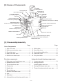
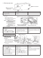
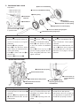
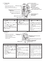
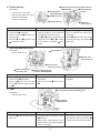
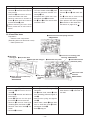
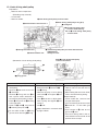
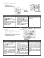
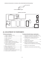
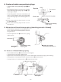
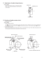
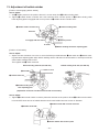
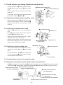
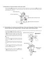
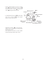
1-NEEDLE LOCKSTITCH SEWING MACHINE WITH
AUTOMATIC THREAD TRIMMER FOR PROFESSIONAL
TL-2010Q/2000Qi
SERVICE Manual
CONTENTS
[1] Specifications of TL-2010Q/2000Qi........................................................ 1
[2] Names of Components............................................................................ 3
[3] Disassembly and Assembly................................................................... 3
[4] Printed Circuit Board Diagram (Connector Layout).............. 15
[5] Adjustments of Components............................................................ 16
WARNING :
To avoid the risk of fire, electric shock, injury to persons or damage to components, especially keep the
following :
• When disassembling, assembling or adjusting the sewing machine, remove the power plug.
• When assembling, be careful about the electrical cord being caught with other components,
damage to the covered parts of the cord or miswiring.
• When replacing the part(s), use the genuine part(s).
[1] SPECIFICATIONS OF TL-2010Q/2000Qi
(1) Power switch
ON•OFF 2-step changeover switch (common to lamp) located at the belt cover section of the right-hand
side of main unit.
(2) Drive control components
Drive
Control
: Built-in motor timing belt method
: Foot pedal controller method 50 to 1,500 sti/min
Low speed rotation of 50 sti/min while needle up/down switch is ON
(3) Table, stand and handle components
Main unit :
Handle :
Table/stand:
Portable type main unit with soft case (Case is folded in two and packed with main unit.)
One-touch type auxiliary table knee lifter is provided as standard. (Packed together)
Pull-up/down from machine main unit type
Separately sold fully-sunken type table and stand can be used.
(4) Arm and bed components
Material : Aluminum die casting arm and bed separate body type
Bed form : Flat bed portable type
(5) General mechanism
1. Thread take-up : Slit type link thread take-up for one-touch threading
2. Hook
: DB type horizontal full-rotary hook
3. Pressing pressure adjustment : Stepless adjusting screw with pressing pressure indicator method
4. Lighting device
: Built in face cover Switch : Slide type Lamp : Halogen lamp
5. Needle thread post
: Two posts for small thread spool and large thread spool
Thread guide of thread post is of draw-out type and capable of
one-touch threading
6. Bobbin thread winder
: One-touch action : Starting method by controller Automatic stop when bobbin thread winding completed
7. Needle thread threading
: One-touch threading from thread spool to needle tip
8. Presser foot
: Commercially-available presser foot for industrial sewing machine (SL2) can be used. (Setscrew type)
9. Lift of presser foot : By lever
: 7 mm Max. by lever : 10 mm By knee lifter : 12 mm
10. Thread tension
: Disk pressure adjusting type with simplified disk pressure scale
11. Drop feed
: 2-step changeover by knob method (Feed dog : UP : DOWN)
12. Power switch
: ON • OFF 2-step
(6) Feed mechanism
1. Feed amount adjustment
2. Reverse feed stitch
: Dial method ...... Stepless 0 to 6 mm
: Lever method .... Feed amount conforms to that of normal feed stitch.
––
(7) Special mechanism
1. Automatic thread trimming
: Thread trimming switch is used in common for pushbutton type and for external foot pedal switch type.
Switch fails to work even when pressing it within two seconds after
the rotation of thread trimmer.
2. Needle bar stop position
: Electric brake stop method
Stop by controller
: Down stop
Stop by automatic thread trimming
: UP stop
Stop by bobbin winder
: UP stop
3. Automatic needle hole threading: Hook section rotates and automatically returns by lowering threading lever.
4. Needle up/down switch
: Switch is of pushbutton type and up/down stop can be performed by
half rotation of main shaft when operating switch for a short period of
time. When switch is continuously held ON, sewing machine
continuously runs at a speed of 80 sti/min until switch is turned OFF.
5. Prevention of reverse setting of needle : Needle is attachable to normal direction only.
6. Motor protection
Overcurrent
: When motor is locked for 0.5 to 1 second due to sudden overload,
motor power is automatically turned OFF and returns to the ON state
immediately.
Overheat
: When motor temperature has abnormally risen, motor power is turned
OFF(thermal cut) and returns to the ON state when temperature has
fallen.
(8) Dimensions and weight
Main unit : 452W x 219L x 350H (mm)
Weight
: 11.5kg
(9) Power consumption
Whole sewing machine
: 120V 1.4A 60Hz
––
[2] Names of Components
TL-2000Qi
Thread guide No.1
Thread guide base
TL-2010Q
First tention
Presser spring regulator
Indicating needle of
presser spring regulator
Thread guide rod
Arm cover asm.
Bobbin winder shaft
Belt cover
Face cover
Handwheel
Stitch dial
Pressure indicating plate
Needle up/down switch
Speed limit vr knob (only for TL-2010Q)
Thread take-up thread guide
Thread take-up spring
Automatic thread trimming switch
Presser bar connection thread guide
Reverse feed stitch lever
Hand lifter lever
Drop-feed knob
LED lamp
Bed cover
Needle bar thread guide
Needle bar thread bracket
Bed cover rubber seat
Side cover
Hole for knee lifter lever setting
Throat plate asm.
Standard presser foot asm.
Thread take-up spring adjusting plate
Needle threader lever
[3] Disassembly/assembly
Page
Outer Components
1. Arm cover asm. ......................................4
2. Belt cover and motor cover .................... 4
3. Face plate asm. ......................................4
4. Bed cover mas. asm. ..............................5
5. MAIN circuit board asm. .........................5
Function components
1. Motor asm. and transformer asm. ..........5
2. Handwheel and clutch ............................6
3. Thread tensioner asm. ........................... 6
4. Presser bar .............................................7
5. Needle bar ..............................................7
6. Thread take-up ....................................... 8
7. Reverse feed stitch lever ........................8
8. Idler ........................................................ 8
9. Stitch dial ................................................9
10. Automatic thread trimming switch case ..9
Page
11. Wire holder .............................................9
12. Knee lifter lever .................................... 10
13. Hook driving shaft pulley ...................... 11
14. Hand lifter lever .................................... 12
15. Drop-feed knob ..................................... 12
Automatic thread trimming components
1. Looper mas. asm. ................................. 13
2. Moving knife arm
installing plate mas. asm. ..................... 13
3. Moving knife base mas. asm. ............... 14
4. Thread trimming solenoid mas. asm. ... 14
––
Outer Components
1. Arm cover asm.
6 Convex of presser
spring regulator knob
1 Arm cover setscrew
SM5042005SN
2 Bobbin
4 MAIN circuit winder
board case cover connector
3 Arm cover
Disassembly
™Remove two 1 setscrews.
™Disconnect and remove 2 connector.
5 Slit of presser regulating screw
Assembly
™Insert 2 connector.
™Align 6 convex with 5 slit and
tighten the setscrew.
Point
™There should be no torsion or
distorsion in presser spring regulator.
™Align precisely slit portion with
convex portion.
™Do not press each lead wire.
2. Belt cover and motor cover
1 Belt cover setscrew SM5041255SN
Disassembly
™Remove four 1 setscrews and
remove belt cover.
™Remove three 2 setscrews and
remove motor cover.
3. Face plate asm.
Preparation
™Remove arm cover.
2 Motor cover setscrew SM5041255SN
Assembly
Point
™Attach belt cover and tighten 1 ™There should be no difference
setscrews.
in level between belt cover and
front face of frame.
™Attach motor cover and tighten
™Make motor cover come closely 2 setscrews.
contact with belt cover.
1Lamp connector
5Face cover
4 Indicating needle of
presser spring regulator
3Face plate asm.
2Face plate asm. setscrew
SL5040631SE
Disassembly
™Disconnect 1 connector and 6
remove.
™Remove 2 setscrews and remove 3 face plate asm.
(together with face cover).
6Hand lifter lever spring
Assembly
face
plate asm., tighten
™Attach 3
it with face plate asm. 2 setscrews, and attach 6 hand lifter
lever spring.
™Insert 1 connector.
––
Point
should
be no difference in
™There
level around the cover when face
cover is closed.
™5 should not come in contact
with 4 indicating needle.
4. Bed cover mas. asm.
1 Bed cover setscrew
1 Bed cover setscrew SM5051255SN
Disassembly
™Remove six 1 setscrews and remove bed cover.
5. MAIN circuit board asm.
Preparation
™ Remove arm cover asm.
™ Remove MAIN circuit board case
cover and lamp connector.
Note) 3 Setscrew to set the
circuit board and cover
to circuit board case
Do not insert in the
reverse direction.
(See page 15.)
Do not loosen this
screw.
Disassembly
™Remove 7 connectors of each
lead wire.
™Cut 6 clip bands (3 places).
™Remove 2 setscrews and 4 setscrew, and remove circuit board.
Function Components
Assembly
™Attach bed cover and tighten setscrews.
Point
3 MAIN circuit board setscrew 2 MAIN circuit board case setscrew A
SL5030831SF
Porality exists.
4 MAIN circuit board case
setscrew B SM5031401SE
6 clip band (3 places)
Never loosen this screw.
Assembly
play
of circuit board to at™Press
tach circuit board to the front side
and tighten two setscrews.
™Insert each lead wire into connectors.
Point
the
note
and understand it.
™Read
™Ther are color indications on the
circuit board for inserting connectors.
3 Motor setscrew nut
1. Motor asm. and
transformer asm.
Preparation
™ Remove arm cover asm.
5-1
™ Remove belt cover and 5 Cord guide
plate setscrew
motor cover respectively.
SM5030655SN
Make a memorandum of
4
cord wiring.
Disassembly
™Remove cord guide plate 5 setscrews and 5-1 in previous item,
and cut 6 clip band.
™Loosen 4 cord presser.
™Remove two 1 setscrews and
remove motor asm.
™Remove two 2 setscrews and
remove transformer asm.
Make sure of wiring route.
1 Motor asm.
setscrew
SM5050855SN
2Power
transformer
setscrew
SM5040855SN
Assembly
™Attach transformer and tighten
3 setscrews.
™Attach motor asm. and tighten
1 setscrews.
™Fix it with 4 cord presser.
™Attach cord guide plate asm. and
tighten 5 and 5-1 setscrew.
™Connect cord guide plate and
cord.
––
Point
™Loosen 3 nuts to adjust motor
tension.
™Belt tension : the belt should sag
3 to 4 mm when center of belt is
applied with 1.96N load.
2. Handwheel and clutch
!0 Groove of handwheel
Preparation
™ Remove belt cover.
™ Remove arm cover.
7 Convex of handwheel bushing
1 Handwheel
setscrew
9 Motor pulley
6 Groove of
handwheel bushing
2 Handwheel
5Hook portion of clutch spring
4 Angle portion of clutch spring
When removing motor
pulley, remove cord guide
plate setscrews 5 and 5-1
in previous item.
Disassembly
™Remove 1 setscrew.
™Remove cord guide plate setscrew and remove cord guide
plate asm.
™Remove 3 spring support.
™Move 4 in the direction where
clutch spring is released and remove clutch spring.
™Face 6 to motor side and 8 is
hard to drop.
™Draw out 8 and remove 9.
3Groove of clutch spring support
8Handwheel bushing stopper pin
Assembly
Point
™Attach 9 and enter 8.
™Align 7 convex of bushing with
!0 groove of handwheel and at™Enter 6 groove of bushing to 8
tach handwheel. Then tighten
stopper pin and attach bushing.
setscrew.
™Enter 5 hook portion of spring
to slit in the center of handwheel ™Clearance provided between conbushing
vex of 3 clutch spring support
and clutch plate is 2 ± 0.5 mm.
™E n t e r 5 c l u t c h s p r i n g t o 3
groove of spring support and at- ™See item 12 on page 19 for adtach cord guide plate asm. Then
justment.
tighten setscrew.
3. Thread tensioner asm.
3 Thread take-up spring
4 Thread tensioner asm.
5 Thread tension disk presser
2Thread tensioner setscrew
SM8040602TP
6 Thread take-up
spring adjusting
plate
1Thread take-up spring
adjusting plate setscrew
SL5030801SN
Disassembly
Assembly
Point
™Remove 1 setscrew.
™Attach 6 adjusting plate and 3 ™Place upward the scale of 5
spring to thread tensioner asm.
thread tension disk presser.
presser
foot
and
remove
™Lower
2
and attach it to frame. Then fix it ™See items 9 and 10 on page 19
setscrew.
with 2 setscrew.
for adjustment of pressure and
™Remove 3 spring together with
thread take-up spring of stroke.
4 thread tensioner asm. and ad- ™Tighten 1 adjusting plate setjusting plate.
screw.
––
4. Presser bar
2Presser spring regulator
Threader support plate
setscrew (upper)
SL5040631SE
Preparation
™ Remove arm cover asm.
4 Presser spring
™ Remove face plate mas. asm.
7Indicating needle of
presser spring regulator
Threader support plate mas. asm.
™ Remove presser foot and setscrew.
1Presser bar connection setscrew
SM8060502TP
5Presser bar connection asm.
6Presser bar lifting lever
Threader support plate
setscrew (lower)
SM4040655SN
8Hand lifter lever
3Presser bar
Disassembly
Point
Assembly
™Lower 8 lever and loosen 1 set- ™Attach regulator 2 screw.
™Set 4 spring under 7 indicating
screw.
needle.
™Set 6 lever to frame, and then
™D r a w i n g 3 u p w a r d , r e m o v e 4
set 5 connection.
™Lower 8 lever and temporarily
spring.
tighten it at the position where top
™Attach 4 spring when setting
™Remove 5 connection and 6 lever.
end of 3 protrudes approximately
3 presser bar from upper side.
™Remove regulator 2 screw.
4 mm from frame.
™Do not remove 7 indicating needle.
For the adjustment, see item 3 on
3 is hard to remove since secrew
page 17.
mark is attached.
™Needle should not interfere with
presser foot.
5. Needle bar
1 Needle bar upper bushing felt
Preparation
Needle bar crank
™ Remove arm cover asm.
left screw
™ Remove face plate mas. asm.
2Needle bar connection setscrew
SM8060510SP
™ Remove presser bar.
™ Remove needle bar threading
guide as well.
6 Needle bar threader guide setscrew
5 Needle bar
Disassembly
™Remove 3 and 4.
™Remove 1 felt. (Push up needle
bar upper bushing 1 felt with 5
and draw it out.)
™Loosen setscrew of 2 and 6 .
(Pushing needle bar 5 upward is
acceptable.)
™Draw out 5 upward.
™Remove left 6 screw and remove
crank rod.
3Needle bar thread bracket
setscrew A1420-001-000
4 Needle clamp
Assembly
Point
™Attach crank rod and tighten it with ™Position of needle bar is the
place where upper engraved
6.
line of needle bar is aligned
™Perform positioning of needle bar
with lower end face of needle
and tighten needle bar connection
bar bushing at the needle lower
2 setscrew.
dead point.
™Set needle bar and attach 4 and
See item 2 on page 17 for the
3.
adjustment.
™Insert 1 into hole.
™Temporarily tighten 6, and perform ™See item 15 on page 22 for
adjustment of vertical height after
height adjustment of threader
attaching threader support plate
hook of threader support plate
asm.
mas. asm.
––
6. Thread take-up
Preparation ™ Remove arm cover asm.
™ Remove face plate mas. asm.
™ Remove presser bar.
™ Remove needle bar.
1Thread take-up supporting shaft setscrew
SM8050602TP
6Thread take-up
3 Thread take-up
supporting shaft
support
4Needle bar crank
5 Thread take-up
2 Needle bar
crank setscrew
Disassembly
Assembly
Point
™Loosen 1 setscrew.
™Set needle bar crank to thread ™Tighten setting portion (flat portion) of needle bar crank with
take-up, attach it onto main unit
™Loosen two 2 setscrews.
and tighten setscrews (2 pcs.).
screw No. 1.
™Draw out thread 3 take-up supporting shaft.
™Set 6 to 5, enter thread take-up ™Press 3 shaft to frame side while
supporting shaft 3 to 6, attach
viewing the torque and tighten 1
™Remove 5 and 6 together with
it onto frame and tighten 1 setsetscrew.
4 needle bar crank.
screw.
7. Reverse feed stitch lever
Preparation ™ Remove belt cover.
5 Feed regulator
4Reverse feed
stitch lever arm
1Reverse feed
stitch lever spring
3Reverse feed stitch
lever mas. asm.
2Reverse feed stitch lever
setscrew SM5040855SN
Disassembly
Assembly
Point
™Remove 1 spring from arm.
™Attach 3 lever and set with 2 ™Set 4 lever arm to the slot of 5
setscrews.
regulator.
™Remove two 2 setscrews.
™Remove 4 lever arm from the ™Hook lever spring 1 to lever arm
slot of 5 regulator when remov4.
ing 3.
8. Idler
2Convex portion of idler installing plate
Preparation
™ Remove belt cover.
1Idler setscrew
SM5040855SN
Disassembly
Assembly
Point
™Remove 1 setscrew and remove ™Assemble idler and tighten it with ™Belt tension can be changed only
idler asm.
by removing belt cover. Move 2
1 setscrew.
convex portion to the left or right.
™Belt tension : Belt sags 6 to 7 mm
when center of the belt is applied
with a 1.96N load.
––
9. Stitch dial
Preparation
4 Feed regulating screw
™ Remove arm cover asm.
5Feed regulating screw
• Stopper screw
• Stopper nut
2Feed regulating
pin
1Stitch dial setscrew
SM8030402TP
3Feed regulating screw
stopper asm. setscrew
Disassembly
Assembly
Point
™Loosen two 1 setscrews and re- ™Turn regulating 4 screw full to ™There should be no play in feed
move the dial.
the right.
regulator when operating lever.
(When scale is 0.)
™Be careful since 2 pin jumps.
™Assemble stitch dial with its scale
0 up and tighten 1 screw (2 ™Loosen 5 stopper nut. Make
™3 may not be removed.
stopper screw strike against regupcs.).
(Stopper screw SM8031400TP)
lating 4 screw and tighten nut.
10.Thread trimming switch case
Preparation
™ Remove arm cover asm.
™ Remove motor cover and belt cover.
1Thread trimming switch
circuit board case setscrew
SL4040655SN
™ Remove motor mas. asm.
Disassembly
Assembly
™R e m o v e t w o 1 s e t s c r e w s i n ™Attach the switch case to frame thread trimming switch case.
and tighten with 1 setscrews.
™Remove thread trimming switch
case.
Point
™There should not be no torsion
between switch and frame.
11.Wire holder
2Wire tube presser setscrew
SM4040655SN
Preparation
™ Remove outer components.
(Excluding belt cover and
1Nut of setscrew
(opposite side 9 mm)
NS6620310SP
motor cover)
™ Remove presser bar.
3Wire holder setscrew
SM5040855SN
4 Thread release plate
5Disk pressure release
connecting link
6 Thread release plate shaft
––
Disassembly
™Remove 1 nut (left side only).
™Remove 2 setscrew and remove
tube presser.
™Remove 3 setscrews and remove wire holder mas. asm.
™Remove setscrew in thread release 6 plate shaft and remove
thread release 4 plate.
When removing the wire from
frame, make sure of wire route in
frame.
Assembly
™Lay wire in frame.
™Connect thread release 4 plate
with disk pressure release connecting 5 link.
™Assemble wire holder mas. asm.
and tighten with 3 setscrews.
™Fix 2 and 1 in the reverse side
of machine bed.
12. Knee lifter lever
Point
™Pass the wire through full reverse
side of stitch dial.
™Contact 4 and 5 with each other.
™For 2, tube has to come out by
13 mm from tube presser.
™Tube presser and tube regarding
2 should be on the same face.
See item 5 on page 27 for 1.
1Knee lifter lever shaft spring setscrew
SM5030455SF
Preparation
™ Remove outer components.
(Excluding belt cover and motor cover)
™ Raise presser foot.
!0 Knee lifter
lever shaft
6 Knee lifter lever
4 Knee lifter link snap pin
Disassembly
™Remove snap 4 pin.
™Remove 5 setscrews and remove 6.
™Remove 1 setscrew and take out
lever spring.
™Lower 2 and turn it to the position where 3 can be removed.
™Remove 3 , remove claw lever
actuating plate, and draw out 2.
™Remove claw lever shaft 7 setscrew.
™Remove 8 link asm..
2 Knee lifter lever shaft
9 Claw lever
actuating
plate
5Knee lifter lever shaft stop
plate setscrew
SM5040855SN
3Claw lever actuating plate
setscrew SM8040602TP
8Knee lifter link asm
(claw lever plate)
7Claw lever shaft
setscrew
SM5041255SN
Assembly
Point
™Attach 8 to frame and tighten 7 ™There should not be a play in the
setscrews.
axial direction of 2 knee lifter lever shaft.
™Set 2 lever shaft, attach 9 claw
lever actuating plate and tighten it
with 3.
™Attach lever spring and tighten
with 1.
™Raise frame, attach 6 knee lifter
lever to knee lifter lever !0 shaft,
and tighten it with 5.
™Enter 4 snap pin.
– 10 –
13. Hook driving shaft pulley
Preparation
™ Remove outer components.
(Excluding stop solenoid)
™ Loosen idler.
™ Remove needle.
5Hook driving shaft pulley eccentric shaft
3Hook driving shaft pulley E-ring (E-6)
1 Timing belt
9Thread trimmer cam screw No. 1
6Hook driving shaft pulley
eccentric shaft bushing
Slit on 4 hook driving shaft pulley
eccentric shaft
A B
!0Moving knife roller arm
!1 Thread trimmer cam
2Hook driving shaft pulley eccentric shaft setscrew
SM8040602TP
Hexagon 2.0 mm
Make 7 hook driving shaft pulley
come out downward.
(Illustration of hook driving shaft pulley)
6
4
5
8 E-ring groove
Disassembly
™Remove timing belt from main
shaft pulley.
™Remove 1 belt and loosen two
2 setscrews.
™Remove 3 E-ring and turn 4 to
find a place where backlash in
hook driving shaft pulley is large.
™Press 5 and push out 6 bushing
to the right side.
™Draw out 5 and 6, and remove
7 following the point of 7.
Assembly
Point
When setting 6 bushing, do not
™Enter hook driving shaft 7 pulley.
make a flaw on the end face of
™Enter eccentric 5 shaft and 6.
bushing.
™Set 3 E-ring.
When setting belt onto main shaft,
™Remove the play in hook driving
shaft with 6 and tighten 2 setrefer to thread trimming timing.
screw B.
(Simple method)
™Turn 4 shaft slit to adjust back- ™Lower needle bar 1.95 mm from
lash in pulley and tighten 2 setits upper dead point.
screw A.
™Turn hook driving shaft and orient
™Set 1 belt.
9 screw No. 1 to this side (just
front).
Adjust backlash in eccentric shaft
™Enter contact of !0 roller arm to
Do not make a flaw on 8 E-ring
by right rotation.
groove of !1 cam.
groove when removing 3 E-ring.
™Turn hook driving shaft in the reverse direction and set belt at the
position where it stops.
– 11 –
14. Hand lifter lever
1 Hand lifter lever
4 Hand lifter lever shaft set screw
Flat part
2 Hand lifter lever shaft
3 M4 screw
a
Disassembly
Assembly
Point
™Loosen hand lifter lever shaft set- ™Put hand lifter lever shaft 2 into ™End face a of hand lifter lever
the hole in the frame.
shaft 2 should not jut out from
screw 4.
the frame surface.
™Insert M4 screw 3 into tapped ™Secure hand lifter lever shaft 2
hole in hand lifter lever shaft 2 by
by tightening hand lifter lever
3 to 4 screw threads.
shaft setscrew 4 in such a way
that the tip of setscrew 4 comes
™Hold screw head and draw out the
in contact with the flat part on
screw.
hand lifter lever shaft 2.
™At the same time, also draw out
hand lifter lever shaft.
™Remove hand lifter lever 1.
15. Drop-feed knob
1 Drop-feed knob
3 E-ring
5 Wire installing plate asm.
2 DF adjusting arm spring
6 DF adjusting arm asm.
4 Drop feed knob shaft setscrew
Disassembly
Assembly
Point
™Set 1 drop-feed knob to "NOT ™Pass 1 drop feed knob through ™It is easy to remove 2 spring
FEED", remove 4 drop feed knob
when 1 drop-feed knob is set to
5 wire installing plate.
shaft setscrew, and remove 3 ™Assemble 2 DF adjusting arm
“NOT FEED” side.
E-ring of drop feed knob.
spring while assembling 6 DF
adjusting arm asm..
DF
adjusting
arm
™Remove 2
spring while removing 6 DF ad- ™Place 3 E-ring to 1 drop feed
justing arm asm..
knob.
™Assemble drop feed knob shaft
with 4 setscrew.
– 12 –
Automatic Thread Trimming Components
1. Looper mas. asm.
5Looper mas. asm.
setscrew
SM5040855SN
3 Looper link asm.
Preparation
™ Remove bed cover.
6 Looper 2Looper link holding shaft 4 M o v i n g k n i f e 1 Looper link B
arm spring
7Bobbin case
(Washer A1731090000
E-ring E-3
(Center of inner hook)
E-ring E-3)
Disassembly
Assembly
Point
™Remove 1 E-ring.
™Attach looper mas. asm. and ™Place 6 looper in the center 7
of inner hook and securely tighten
tighten 5 setscrews. (Adjust
™Remove E-ring and washer of 2.
looper link B shaft to hole.)
™Remove looper link asm of 3.
5.
S e e i t e m 4 - 2 o n p a g e 2 7 f o r
™Remove moving knife arm spring ™Hook moving knife arm 4 spring.
of 4.
adjustment of looper moving
™Set looper link and attach E-ring,
amount.
and
resetscrews
of
washer,
etc.
™Remove
5
move looper mas. asm.
2. Moving knife arm installing plate mas. asm.
Preparation
™ Remove bed cover.
™ Remove 2 looper mas. asm..
2Looper
mas.asm
3Nut (9 mm) of wire 4Moving knife arm installing plate
mas. asm. set screw SM4050855SP
setscrew
™ Remove moving knife arm 6 spring.
8Thread trimmer clutch
plate collar
Thread trimmer clutch plate
7
Moving
knife
link
5
Moving
knife
link
shaft
A
1
collar setscrew
E-ring E-4
6Moving knife arm spring
Disassembly
™Remove 1 E-ring.
Do not remove 5 moving knife
link. (Remove together with moving
knife arm installing plate.)
™Remove 3 nut on the left side
only.
™Remove thread trimmer clutch
plate 7 collar setscrew and 8
thread trimmer clutch plate collar.
™Remove two 4 screws and remove installing plate mas. asm.
At this time, simultaneously remove moving knife link.
( To prevent moving knife link from
warping)
Assembly
™Attach moving knife arm installing
plate mas. asm.
Note : See the point on the right side.
™Temporarily tighten 4 setscrews.
™Attach 1 E-ring of link shaft.
™Temporarily tighten 2 looper
mas. asm..
™A t t a c h 6 m o v i n g k n i f e a r m
spring.
™Determine position of moving
knife and securely tighten 4.
Note : Refer to assembling of moving
knife and looper mas. asm.
– 13 –
Point
™Set 1 moving knife link and wire
3 setscrew.
™Position of moving knife
Remove hook and see from the
reverse side of bed.
(See item 1 on page 23.)
™See item 5 on page 27 for adjustment of 3 nut of wire.
3. Moving knife base mas. asm.
Preparation
™ Remove bed cover.
™ Remove throat plate asm.
3Feed dog
2M o v i n g k n i f e
base mas. asm.
setscrew
SM4040855SP
Disassembly
™R e m o v e 1 E - r i n g a n d r a i s e
frame.
™Remove two 2 setscrews.
™Bring 3 feed dog to its highest
position.
™Raising moving knfe base by
hand, lightly press moving knife
link A from upper side.
(Release coupling.)
Assembly
Point
™Attach moving knife base to frame ™When assembling, it is better to
while setting moving knife base to
raise by finger moving knife link A
moving knife link shaft A.
from below.
™Temporarily tighten 2 setscrews.
™Push moving knife base in the
direction of right rear 45˚ and securely tighten it.
™Tilt frame, set moving knife link
shaft A and enter 1 E-ring.
4. Thread trimmer solenoid mas. asm.
Preparation
1Moving knife link
shaft A E-ring
™ Remove outer components.
(Remove arm cover asm., belt cover, motor
1Thread trimmer
solenoid link A 5 Moving knife
roller arm
Washer and E-ring
4 Moving knife arm
cover and cord guide.)
™ Remove solenoid cover.
™ Remove washer, E-ring and eccentric shaft of
thread trimmer solenoid link A.
3Thread trimmer solenoid
mas. asm. setscrew
SM5040655SN
Eccentric shaft setscrew
Disassembly
Assembly
Point
™Remove washer, E-ring, eccentric ™Attach thread trimmer solenoid ™Move thread trimmer solenoid
shaft and setscrews of 1 thread
and temporarily tighten it with 3
asm. to the left and right so that
trimmer solenoid link A.
setscrews.
pin at top end of thread trimmer
auxiliary link comes in contact
™Remove 1 thread trimmer sole- ™Adjust clearance between pin at
with thread trimmer auxiliary
noid link A.
top end of thread trimmer auxilcam when the solenoid performs
iary link and thread trimmer aux™Remove three setscrews in thread
suction and securely tighten settrimmer solenoid asm. to take it
iliary cam to 0.5 to 1.0 mm and
screws.
out.
securely tighten 3 setscrews.
* It is easy to remove setscrews ™Fix 1 thread trimmer solenoid * Solenoid has to properly work
when the solenoid performs sucwhen top end of thread trimmer
link A with eccentric shaft, washer
tion.
auxiliary link is moved to the rightand E-ring.
hand side of thread trimmer auxil- (See item 2 on page 23 and item
iary cam.
3-5 on page 24 for the adjustment.)
– 14 –
[4] PRINTED CIRCUIT BOARD DIAGRAM (CONNECTOR LAYOUT)
VR for speed
limiting
2
Controller
Thread trimmer
socket
2
External thread
trimmer SW
2
Controller
socket
CN11
2
3
2
Thread trimmer
SW circuit board
3
3
CN5
CN4
CN1
Bobbin winder SW
CN6
Motor
Power connecting
wire
Transformer
secondary side
(AC 22V, 19.8V)
Lamp
Bobbin winder SW
MP detection circuit
board
CN6
Thread trimmer SW
circuit board
CN3
3
1
2
3
1
2
3
2
CN2
CN23
3
2
CN9
CN8
CN21
2
(AC 22V),
(AC19.8V)
AC120V
Transformer
MAIN circuit board
Terminal
Pin
CN5
1
2
CN4
1
2
CN10
1
2
Description
Blue
Brown
Black
Blue
Brown
Yellow
Yellow
Red
Red
Gray
Gray
Purple
-
FILTER
circuit board
CN22
4
Motor
Cord color
Power SW
2
CN7
3
MAIN circuit board
Terminal
Pin
CN7
1
3
5
CN9
1
2
CN8
1
2
3
4
CN2
1
2
CN1
1
2
Lamp SW
MAIN
circuit board
CN3
MP detection
circuit board
Description
Lamp
Thread trimmer
solenoid
AC120V
Plug socket
Controller socket
Thread trimmer
solenoid
VR for speed limiting
3
FILTER circuit board
Terminal
Pin
CN21
1
2
CN22
1
2
CN23
1
2
Description
Transformer Primary
side (AC 120V)
Power connecting
wire
Power input
(AC 120V)
Gray
Black
Red
Orange
Brown
Cord color
Yellow
White
Blue
Blue
Red
Yellow
Black
Cord color
White
Blue
Brown
Blue
Blue
Yellow
Thread trimmer SW circuit board
Cord color
Terminal
Pin
CN11
1
Black
2
Brown
Description
External thread
trimmer socket
(Caution) 1. CN Nos. in frame of MAIN circuit board denote connector Nos. in MAIN circuit board.
2. Portions enclosed with thick lines denote circuit boards.
3. Numerals outside of frame of MAIN circuit board denote number of lead wires.
CN6
CN4 CN10
CN3
CN5
(MAIN circuit board)
CN2
CN1
CN8
CN7
CN9
– 15 –
(Caution) Convex portion of connectors, CN7, CN8 and CN9 should be placed up.
Convex portion
Connector insertion diagram
(FILTER circuit board)
-
-
〜
1
ZNR1
L2
L1
F1
〜
CN22
BRN
CN21
1
CR1
1 CN23
WHT
C2
C1
BLU
[5] ADJUSTMENT OF COMPONENTS
General mechanism
1. Height of neddle bar bushing............................ 17
2. Height of needle bar.......................................... 17
3. Height of presser foot........................................ 17
4. Height of feed dog............................................. 18
5. Feed timing........................................................ 18
6. Needle-to-hook timing....................................... 18
7. Clearance between needle and hook................ 18
8. Position of bobbin case positioning finger......... 19
9. Stroke of thread take-up spring
(absorbing amount of thread)............................ 19
10.Tension of thread take-up spring......................... 19
11. Bobbin thread tension....................................... 20
12. Position of bobbin winder clutch........................ 20
13. Adjustment of bobbin winder............................. 21
14. Position of threader support plate mas. asm..... 22
15. Vertical position of threader hook...................... 22
Automatic thread trimmer mechanism
– 16 –
1. Positioning of moving knife arm installing plate
(adjustment of position of moving knife)............ 23
2. Installing position of thread trimmer solenoid
(moving amount of thread trimmer cam
contactor shaft).................................................. 23
3. Thread trimmer cam timing
(needle-to-cam position).................................... 24
4. Position and protruding amount of looper
(left/right position and adjustment of movement)
.......................................................................... 27
5. Position of nut of wire setscrew
(adjustment of thread tension disk open/close)
.......................................................................... 27
General Mechanism
1. Height of needle bar bushing
™ Set dimension from top surface of throat plate to
lower end face of needle bar bushing to 67.0 ±
0.1mm. (bushing : driving fit)
Lower end face of needle bar
bushing
67.0 ± 0.1 mm
Top surface of throat plate
2. Height of needle bar
™ Lower dead point of needle bar.
™ Attach length gauge (needle) of #14 needle to needle bar, and adjust dimension from tip of needle to installing plane of throat plate on frame to 17.8 ± 0.1 mm.
™ Perform adjustment with needle bar connection setscrew.
Position of standard
Upper engraved line A on needle bar aligns with
bottom end of 3 needle bar bushing when needle bar is at lower dead point.
Needle bar
connection
setscrew
3
Installing plane of throat plate on frame
A
2
17.8 ± 0.1 mm
Frame
3. Height of presser foot
™ Adjust the height in the state that hand lifter lever
is raised.
™ Clearance provided between top surface of throat
plate and lower face of presser foot is 7.0±0.5
mm.
™ Perform adjustment with presser bar connection
setscrew.
– 17 –
Presser foot
Throat plate
7.0±0.5 mm
4. Height of feed dog
™ Set stitch dial to 2 and bring feed dog to its highest position.
Top surface of throat plate
1.2±0.1 mm
™ See the height on the rear side of feed dog.
™ Bottom of tooth of feed dog should be aligned
with top surface of throat plate.
(Figure on the right side : protruding amount from
top surface of throat plate is 1.2±0.1 mm.)
2 Shaft arm setscrew
™ Perform adjustment with 1 vertical feed shaft
arm.
1 Vertical feed shaft arm
5. Feed timing
™ Set stitch dial to P=2.
™ Lower feed dog in the normal feed operation and align it with top surface of throat plate.
™ At this time, clearance provided between needle top and top surface of throat plate is 0±0.2 mm.
™ Perform adjustment with feed cam setscrew.
Feed cam setscrew
Needle (HA x 1 #14)
Top surface of throat plate
0±0.2 mm
6. Needle-to-hook timing
™ Loosen three setscrews in hook.
™ Adjust blade point of hook and left edge of needle
to 0 to 0.2 mm when needle bar lifts by 2.17 mm
from its lower dead point.
1.33 mm
™ Check clearance between needle and hook, and
tighten setscrews.
Remove bobbin case positioning finger to improve the work.
Standard of position of 2 mm from lower dead
point of needle bar is that of engraved lines 1 to
2 on needle bar.
2
1
Hook
(1 Lower dead point, 2 Position of lifting 2 mm)
7. Clearance between needle and hook
™ Loosen three setscrews in hook.
™ Adjust blade point of hook to position of 0.2 mm
from left edge of needle.
™ Adjust clearance between blade point of hook
and needle to 0.02 to 0.07 mm.
™ Temporarily tighten setscrews, check timing, and
securely tighten setscrews.
– 18 –
Lifting amount
2.17 mm
0 to 0.2
0 to 0.2
Needle
Blade point
0.02 to 0.07 mm
8. Position of bobbin case positioning finger
™ Loosen bobbin case positioning finger 1 setscrew.
™ Make right-hand edge of convex portion of bobbin
case positioning finger spring align with 2 righthand edge of needle.
™ Temporarily tighten setscrew, hold clearance of
0.3 to 0.5 mm between inner hook and bobbin
case positioning finger, and securely tighten setscrew.
Top view
Needle
0.3 to 0.5 mm
3
Front view
Bobbin case positioning finger should not come
in contact with hook.
Bobbin case positioning finger
Needle
1
Bobbin case positioning finger should not interfere with hook.
2
Bobbin case positioning
finger spring
9. Momentum of thread take-up spring (absorbing amount of thread)
™ Thread take-up spring has to be installed at position of 10±0.5 mm from thread guide as shown in
the figure below.
™ Perform adjustment with 1 thread take-up spring
adjusting plate.
10.5±0.5 mm
Thread tensioner
thread guide
1Thread take-up spring
adjusting plate and setscrew
Thread take-up spring
adjusting plate.
10. Tension of thread take-up spring
™ Pass needle thread up to 1 thread tensioner thread guide.
™ Lower presser foot and draw needle thread.
™ Adjust tension of thread take-up spring to 0.176 to 0.245N when thread take-up spring starts lowering.
™ For adjustment, loosen thread tensioner setscrew and turn 3 thread tensioner.
™ Turning clockwise = increasing tension of 4 thread take-up spring.
4Thread take-up spring
Needle thread
2Thread tensioner
setscrew
3Thread tensioner
asm.
– 19 –
1Thread tensioner
thread guide
11. Adjustment of bobbin thread tension
How to adjust
Adjust with adjusting screw so that bobbin thread
tension when spun thread #60 is used becomes
0.176±0.02N.
Bobbin case
Adjusting screw
Bobbin thread
12. Position of bobbin winder clutch
™ Remove belt cover.
How to adjust
1. Bobbin winder OFF state
Turn 3 thread trimmer clutch plate link collar and adjust so that a clearance of 2±0.5 mm is provided between 1 bobbin winder clutch plate and 2 clutch plate spring support, and temporarily tighten 4 setscrew.
2. Bobbin winder ON state
Make sure that bobbin winder clutch plate comes in contact with inner ring of clutch plate spring support and
securely tighten thread trimmer clutch plate link collar setscrew.
Bobbin winder OFF
Bobbin winder shaft
base adjusting plate
1 Bobbin winder
clutch plate
Bobbin winder ON
4 Link collar setscrew
3 Thread trimmer
clutch plate link
collar
2C l u t c h p l a t e
spring support
2±0.5 mm
– 20 –
To come in contact with each other
13. Adjustment of bobbin winder
[Position of disengaging bobbin winder]
How to adjust
1. Set 1 bobbin presser to the position where it is 16 mm away from 2 bobbin winding shaft.
2. Tighten 4 bobbin winder controller asm. with setscrew when concave portion of 3 bobbin winding shaft
base adjusting plate is engaged with convex portion of 4 bobbin winder controller asm..
4 Bobbin winder controller asm.
2 Bobbin winding shaft
Setscrew
16 mm
1 Bobbin presser
To engage with each other
To strike
3 Bobbin winding shaft base adjusting plate
[Position of leaf switch]
How to adjust
1. Adjust so that a clearance of 0.9 mm or more should be provided between 1 leaf switch and 2 bobbin winding shaft base adjusting plate when bobbin winding shaft is ON and so that leaf switch is securely turned ON
when bobbin winding shaft is OFF.
Then tighten leaf 3 switch setscrew.
Bobbin winding shaft ON (leaf SW OFF)
1 Leaf SW
Bobbin winding shaft OFF (leaf SW ON)
0.9 mm or more
3 Leaf SW setscrew
2 Bobbin winding shaft
base adjusting plate
[Adjustment of amount of bobbin thread wound round bobbin]
How to adjust
1. Tighten 1 bobbin winder switch contactor plate with setscrew at the position where 2 bobbin winder switch
is turned OFF when amount of bobbin thread wound round bobbin becomes 18 mm in diameter.
3 Bobbin winder SW contactor setscrew
2 Bobbin winder SW
1 Bobbin winder SW contactor plate
– 21 –
14. Position of threader support plate mas. asm.
How to adjust
™ Open face cover and remove arm cover asm.
1. Temporarily tighten 1 threader support plate
mas. asm. with setscrews.
2. Adjust 1 threader support plate mas. asm. so
that position of threader shaft is 10.5 mm, making
needle bar as reference. Then securely tighten
setscrews 2 and 3.
Needle bar
2 Threader support plate
setscrew (upper)
Threader shaft
10.5 mm
(15.675 mm)
1 Threader support
plate mas. asm.
3 Threader support plate
setscrew (lower)
15. Vertical position of threader hook
How to adjust
™ Open face cover.
(Perform confirmation with HAX1 #14 needle.)
1. Turn handwheel by hand to bring needle bar near to highest point. Then stop needle bar at position where 1 needle
bar guide setscrew can be seen from adjustment hole of 2
threader support plate.
2. Press down 3 threader lever to lowest point and check that
clearance between top end of 4 threader hook and top end
of needle eyelet is 0 to 0.1 mm when 4 threader hook is
turned.
3. Insert hexagonal wrench key (1.5 mm) from adjustment hole
of 2 threader support plate and slightly loosen 1 needle
bar guide setscrew.
When hook is lower -> move needle bar guide upward and
temporarily tighten it.
When hook is higher -> move needle bar guide downward
and temporarily tighten it.
Perform adjustment while confirming position in terms of
needle eyelet.
When hook is out of place in lateral direction, perform correction of bend of hook with tip of a thin screwdriver or the like,
or replace 4 threader hook with a new one.
4. When hook is adjusted to aforementioned position, securely
tighten setscrews.
1 Needle bar
guide setscrew
2 Threader
support plate
3 Threader
lever
4 Threader hook
Caution : Hook has to smoothly pass needles HAX1 and HLX5 #11 to #16.
– 22 –
0 mm
Automatic Thread Trimmer Mechanism
1. Positioning of moving knife arm installing plate
(Adjustment of position of moving knife)
™ Loosen 1 nut of setscrew
™ Loosen 2 setscrews in installing plate and move
installing plate to the right or left to obtain position
A.
2 Moving knife arm
installing plate setscrew
1 Nut of setscrew
™ Tighten 2 setscrews in installing plate.
Reference (substitution)
Position of moving knife (see from under side of
bed.)
Overlapping amount of slot 4 of moving knife base
with portion R of moving knife is 0 to 0.5 mm.
(To such an extent that portion R of moving knife is
slightly seen from slot 4)
Figure observed from the
rear after removing hook.
4
Counter knife
Moving knife base
Moving knife base
Align top end of moving knife with border of black
coloring section and polished plane of counter knife.....A
2. Installing position of thread trimmer SOL (solenoid)
™ Move 3 thread trimmer solenoid asm. to the right
and left to adjust so that clearance between 1
thread trimmer auxiliary link and 2 thread trimmer auxiliary cam is 0.5 to 1.0 mm, and tighten it
with 4 setscrews.
When thread trimmer solenoid asm. is set to ON,
it has to interlock thread trimmer auxiliary cam.
0.5 to 1.0
1 Thread trimmer
auxiliary link
3 Thread trimmer
4 Thread trimmer solenoid setscrew
solenoid
2 Thread trimmer auxiliary cam
– 23 –
3. Thread trimmer cam timing (Needle-to-cam position)
™ Loosen setscrews in 1 thread trimmer auxiliary
cam, 2 thread trimmer cam and 3 roller holding
cam.
4 Thread trimmer auxiliary link
1 Thread trimmer auxiliary cam
™ Lower needle bar by 37˚ (1.95 mm) from its upper
dead point.
™ In this state, fix hook driving shaft and perform
positioning of cams of 1, 2 and 3.
3-1 Positioning of [thread trimmer auxiliary cam]
™ Make shaft at top end of 4 thread trimmer auxiliary link of solenoid asm. come in contact with 1
thread trimmer auxiliary cam and tighten it with
setscrew.
3-2 Positioning of [thread trimmer cam]
2 Thread trimmer cam
5 Setscrew No. 1
™ Face front 5 setscrew No. 1 in thread trimmer
cam.
™ Enter 6 thread trimmer cam contactor shaft to
groove in 2 thread trimmer cam.
™ Slightly pressing thread trimmer cam to handwheel side, turn it in reverse direction.
™ Tighten thread trimmer cam with setscrews at
place where idling term of cam groove (place
where rotation is hindered) is finished.
6 Thread trimmer cam
contactor shaft
Link support plate
3-3 Positioning of [roller holding cam]
Setscrew No. 2
3 Roller holding cam
™ Turn pin of link support plate and make it come in
contact with concave portion of 3 roller holding
cam.
™ For lateral position, make 3 roller holding cam
come in contact with 1 thread trimmer auxiliary
cam and tighten it with setscrew.
Convex portion
3-4 Securely tighten setscrews in respective cams
3-5 Adjustment of eccentric shaft of thread trimmer solenoid link A
™ Fix 1 thread trimmer solenoid link A with 2 thread trimmer clutch plate collar, 3 thread trimmer clutch plate
collar setscrew, 4 thread trimmer auxiliary link washer and 5 thread trimmer auxiliary link stopper E-ring.
4 Thread trimmer auxiliary
link washer A31099DC000
5 Thread trimmer auxiliary link
stopper E-ring RE0400000K0
2 Thread trimmer clutch plate
collar A2435033000
3 Thread trimmer clutch plate
collar setscrew
Thread trimmer auxiliary link asm.
A2464D250A0
Looper link arm asm. A1727D250A0A
1 Thread trimmer solenoid link A
– 24 –
3-6 Adjustment of thread trimmer clutch plate collar
™ After assembling 1 thread trimmer solenoid link A, perform adjustment of eccentricity with 2 thread trimmer
clutch plate collar (adjustment of clearance between roller holding cam and link arm support plate) and adjust clearance to 1 to 3 mm.
Roller holding cam
Link arm support plate
2 Thread trimmer clutch plate collar
1 Thread trimmer solenoid link A
1 to 3 mm
3-7 Confirmation of working and positioning of link arm fixing plate (Timing of thread
trimmer auxiliary cam, thread trimmer cam and thread trimmer holding cam)
™ Set thread trimmer solenoid asm. to ON state, and make pin at top end of thread trimmer auxiliary link perfectly align with 1 thread trimmer auxiliary cam.
™ Rotate sewing machine by hand up to flat section
of 1 thread trimmer auxiliary cam (place where
it moves to extreme right-hand side). At this time,
2 thread trimmer solenoid link A moves to righthand side.
1 Thread trimmer auxiliary cam
2 Thread trimmer
solenoid link A
™ Looper link arm works and presses moving knife
roller arm since 2 thread trimmer solenoid link A
moves.
Turn handwheel and confirm time when link support plate pin rides on flat portion of roller holding
cam.
Moving knife arm
™ Confirm that thread trimmer contactor shaft
caulked in 3 moving knife roller arm enters
groove in thread trimmer cam.
3 Moving knife
roller arm
™ Press thread trimmer contactor shaft a section
of 2 moving knife roller arm to make it come in
contact with moving knife arm asm.
a
– 25 –
™ Insert a clearance gauge of 0.5 mm to contact
part of 1 moving knife roller arm asm. and 2
looper link arm asm. and press 2 looper link arm
asm. to 1 moving knife roller arm asm.
2 Looper link arm
5 Nut
0.5 spacer
4 Link arm support
plate
™ In aforementioned state, make 3 link arm fixing
plate come in contact with 4 link arm support
plate pin, and fix it with setscrew.
1 Moving knife
roller arm
™ Adjustment of position of 5 nut of wire setscrew
(Refer to item 5 of adjustment of thread tension
disk open/close, p.27.)
™ After adjustment of position of looper, tighten
looper link setscrew. (Refer to item 4, p.27.)
– 26 –
Setscrew
Roller holding cam
3 Link arm
fixing plate
Link arm support plate pin
4. Position and protruding amount of looper (Left/right position and moving amount)
4-1. Adjustment of left/right position of looper
™ Adjust with looper mas. asm. 2 so that center of inner hook is aligned with center of lopper 1.
2 Looper mas. asm.
1 Looper and inner hook
3 Looper (Convex
that looper cam
pushes out)
1±0.2 mm
4 Looper cam (Position where it
comes in contact with looper)
4-2. Adjustment of moving amount of looper
™ When thread trimmer solenoid is ON, top end of
looper comes in contact with bobbin case.
™ Adjust clearance between convex 3 of looper
and 4 looper cam to 1±0.2 mm. Loosen looper
link 5 setscrew to adjust clearance.
5 Looper link setscrew
4-3. Installing position of looper stopper plate
™ Adjust installing position of stopper so that clearance between looper and looper installing base is
0.5 to 1.0 mm, and tighten stoper plate with setscrew.
0.5 to 1.0 mm
Rubber stopper
5. Position of nut of wire setscrew
Looper
(Adjustment of thread tension disk open/close)
Looper installing bace
™ Lower presser foot.
™ Move thread trimmer solenoid link A with thread trimmer auxiliary cam, Thread tension disk has to open at
the time when roller rides on thread trimmer auxiliary cam. (Disk rise of 0.5 to 0.7 mm at scale 3.5)
™ Perform adjustment with 2 nut on left-hand side after loosening 3 nut on right-hand side.
™ Perform fixing with nut located outside.
Nut of setscrew (Wrench 9 mm)
3
2
1 Thread tension disk
– 27 –
2-11-1. Tsurumaki,
Tama-shi, TOKYO 206-8551, JAPAN
PHONE : (81)42-357-2341
FAX : (81)42-357-2345
Copyright C 2010 JUKI CORPORATION.
All rights reserved throughout the world.
40099556
000510