1
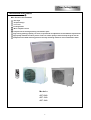
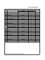
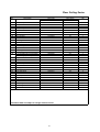
SERVICE MANUAL
FLOOR & CEILING
LARGE SERIES
ASF-09AL, ASF-12AL, ASF-18AL
Floor Ceiling Series
1 . Introduction and Features
Main Function and Features:
New style
Compact design
Low noise
Prolonged filter
Micro computer control
Complete unit of low height,sawing construction space
High cooling (heating) capacity, low noise, 3-speed motor for adjustment to meet different requirements
High-quality materaial and strict process control to ensure quality of the unit and prolong the use life
Compression-moulded water tray,pressure-viscosity insulating material to avoid condensation water
Models
ASF-09AL
ASF-12AL
ASF-18AL
2
Specifications and Technical Parameters
ASF-09AL
Model
COOLING
Function
Rated Voltage
HEATING
220-240V~
Rated Frequency
50Hz
Total Capacity (W/Btu/h)
2500(W)
2800(W)
Power Input (W)
890
980
Rated Input (W)
1200
1140
Rated Current (A)
5.54
3
5.25
550(H)
Air Flow Volume (m /h) (H/M/L)
Dehumidifying Volume (l/h)
1.6
EER / C.O.P (W/W)
2.8
Energy Class
/
ASF-06AL
Model of Indoor Unit
Fan Motor Speed (r/min)
(H/M/L)
Output of Fan Motor (W)
790/670/550
10
Input of Heater (W)
/
Fan Motor Capacitor (uF)
1
0.2
Fan Motor RLA(A)
Centrifugal Fan- 2
Fan Type-Piece
φ125 × 134
Aluminum fin-copper tube
Diameter-Length (mm)
Evaporator
φ7
2/1.6
Pipe Diameter (mm)
Row-Fin Gap(mm)
Indoor
Coil length (l) × height (H)×
unit
coil width (L)
Swing Motor Model
586×25.4×247.6
MP35CA
Output of Swing Motor (W)
2
Fuse (A)
Sound Pressure Level dB
(A) (H/M/L)
Sound Power Level dB(A)
(H/M/L)
Dimension (W/H/D) (mm)
Dimension of Package
(L/W/H) (mm)
Net Weight /Gross Weight
(kg)
PCB 3.15A
45/42/39
55/52/49
836/238/695
935/805/295
27/35.5
3
Floor Ceiling Series
Model of Outdoor Unit
ASF-09AL
Compressor Manufacturer/trademark
Shenyang
Compressor Model
ASG108CV-B7AT
Compressor Type
rotary compressor
18
L.R.A. (A)
4.28
Compressor RLA(A)
922
Compressor Power Input(W)
KA-172-LYGN914
Overload Protector
Throttling Method
Capillary
Starting Method
Capacitor
Working Temp Range (℃)
-50
Aluminum fin-copper tube
Condenser
ф7
2-1.4
Pipe Diameter (mm)
Rows-Fin Gap(mm)
714×25.4×495
Coil length (l)×height (H)×coil width (L)
Fan Motor Speed (rpm)
850
Output of Fan Motor (W)
30
Outdoor Fan Motor RLA(A)
unit
Fan Motor Capacitor (uF)
0.484
2
/
Air Flow Volume of Outdoor Unit
Fan Type-Piece
Axial fan –1
Fan Diameter (mm)
ф400
Auto defrost
Defrosting Method
T1
Climate Type
I
Isolation
IP24
Moisture Protection
Permissible Excessive Operating
Pressure for the Discharge Side(MPa)
Permissible Excessive Operating
Pressure for the Suction Side(MPa)
3.8
1.2
Sound Pressure Level dB(A) (H/M/L)
54
Sound Power Level dB(A) (H/M/L)
64
Dimension (W/H/D) (mm)
848/320/540
Dimension of Package (L/W/H)(mm)
878/360/590
30/34
Net Weight /Gross Weight (kg)
R410A/0.95
Refrigerant Charge (kg)
5
Length (m)
30
Gas additional charge(g/m)
ConneLiquid Pipe (mm)
Outer
ction
Diameter Gas Pipe (mm)
Pipe
Height (m)
Max
Distance Length (m)
6
12
5
10
In case of any change of data,please refer to the nameplate.
4
ASF-12AL
Model
Function
COOLING
HEATING
Rated Voltage
230V~
Rated Frequency
50Hz
Total Capacity (W/Btu/h)
3500(W)
3900(W)
Power Input (W)
1230
1290
Rated Input (W)
1570
1800
Rated Current (A)
8.05
7.5
3
600(H)
Air Flow Volume (m /h) (H/M/L)
Dehumidifying Volume (l/h)
1.6
EER / C.O.P (W/W)
2.8
Energy Class
ASF-12AL
Model of Indoor Unit
Fan Motor Speed (r/min)
(H/M/L)
Output of Fan Motor (W)
790/670/550
10
Input of Heater (W)
-
Fan Motor Capacitor (uF)
1.5
Fan Motor RLA(A)
0.15
Fan Type-Piece
Centrifugal Fan- 2
φ125×134
Aluminum fin-copper tube
Diameter-Length (mm)
Evaporator
φ7
3/1.6
Pipe Diameter (mm)
Row-Fin Gap(mm)
Indoor
Coil length (l)×height (H) ×
unit
coil width (L)
Swing Motor Model
586×38.1×247.6
MP35CA
2
Output of Swing Motor (W)
PCB 3.15A
Fuse (A)
Sound Pressure Level
dB(A) (H/M/L)
Sound Power Level dB(A)
(H/M/L)
Dimension (W/H/D) (mm)
Dimension of Package
(L/W/H) (mm)
Net Weight /Gross Weight
(kg)
46/42/38
56/52/48
836/238/695
935/805/295
27/35.5
5
Floor Ceiling Series
ASF-12AL
Model of Outdoor Unit
Compressor Manufacturer/trademark
Shenyang
Compressor Model
C-RV146H1C
Compressor Type
rotary compressor
L.R.A. (A)
30
Compressor RLA(A)
5.7
Compressor Power Input(W)
1245
Overload Protector
B235-150-241E
Throttling Method
Capillary
Starting Method
Capacitor
Working Temp Range (℃)
-50
Condenser
Aluminum fin-copper tube
ф7
2-1.4
Pipe Diameter (mm)
Rows-Fin Gap(mm)
Coil length (l)×height (H)×coil width (L)
714×25.4×495
Fan Motor Speed (rpm)
850
Output of Fan Motor (W)
30
Outdoor Fan Motor RLA(A)
unit
Fan Motor Capacitor (uF)
0.15
2.5
Air Flow Volume of Outdoor Unit
----
Fan Type-Piece
Axial fan –1
Fan Diameter (mm)
ф400
Auto defrost
Defrosting Method
Climate Type
T1
Isolation
I
Moisture Protection
IP24
Permissible Excessive Operating
Pressure for the Discharge Side(MPa)
3.8
Permissible Excessive Operating
Pressure for the Suction Side(MPa)
1.2
Sound Pressure Level dB(A) (H/M/L)
56
Sound Power Level dB(A) (H/M/L)
66
Dimension (W/H/D) (mm)
848/320/540
Dimension of Package (L/W/H)(mm)
878/360/590
Net Weight /Gross Weight (kg)
40/44
Refrigerant Charge (kg)
R410A/1.25
Length (m)
5
Gas additional charge(g/m)
ConneLiquid Pipe (mm)
Outer
ction
Diameter Gas Pipe (mm)
Pipe
Height (m)
Max
Distance Length (m)
30
6
12
5
10
In case of any change of data,please refer to the nameplate.
6
ASF-18AL
Model
COOLING
Function
HEATING
Rated Voltage
230V~
Rated Frequency
50Hz
Total Capacity (W/Btu/h)
5000(W)
5600(W)
Power Input (W)
1790
2090
Rated Input (W)
2210
2220
Rated Current (A)
11.5
11.5
3
700(H)
Air Flow Volume (m /h) (H/M/L)
Dehumidifying Volume (l/h)
1.6
EER / C.O.P (W/W)
2.8
-
ASF-18AL
Energy Class
Model of Indoor Unit
Fan Motor Speed (r/min)
(H/M/L)
Output of Fan Motor (W)
1070/970/870
40
Input of Heater (W)
-
Fan Motor Capacitor (uF)
Fan Motor RLA(A)
3
0.2
Fan Type-Piece
Centrifugal Fan- 2
φ125 × 134
Aluminum fin-copper tube
Diameter-Length (mm)
Evaporator
φ7
3/1.6
Pipe Diameter (mm)
Row-Fin Gap(mm)
Indoor
Coil length (l)×height (H)×
unit
coil width (L)
Swing Motor Model
586×38.1×266.6
MP35CA
2
Output of Swing Motor (W)
PCB 3.15A
Fuse (A)
Sound Pressure Level
dB(A) (H/M/L)
Sound Power Level dB(A)
(H/M/L)
Dimension (W/H/D) (mm)
Dimension of Package
(L/W/H) (mm)
Net Weight /Gross Weight
(kg)
54/50/46
64/60/56
836/238/695
935/805/295
27/35.5
7
Floor Ceiling Series
ASF-18AL
Model of Outdoor Unit
Hitachi
Compressor Manufacturer/trademark
Compressor Model
ASH218SV-C8LU
Compressor Type
rotary compressor
40
L.R.A. (A)
8.25
Compressor RLA(A)
1785
Compressor Power Input(W)
built in
Overload Protector
Throttling Method
Capillary
Starting Method
Capacitor
Working Temp Range (℃)
-50
Aluminum fin-copper tube
Condenser
ф7
2-1.4
Pipe Diameter (mm)
Rows-Fin Gap(mm)
753×25.4×655
Coil length (l)×height (H)×coil width (L)
Fan Motor Speed (rpm)
780
Output of Fan Motor (W)
60
Outdoor Fan Motor RLA(A)
unit
Fan Motor Capacitor (uF)
0.2
3
----
Air Flow Volume of Outdoor Unit
Fan Type-Piece
Axial fan –1
Fan Diameter (mm)
ф460
Auto defrost
Defrosting Method
T1
Climate Type
I
Isolation
IP24
Moisture Protection
Permissible Excessive Operating
Pressure for the Discharge Side(MPa)
3.8
Permissible Excessive Operating
Pressure for the Suction Side(MPa)
1.2
Sound Pressure Level dB (A) (H/M/L)
59
Sound Power Level dB (A) (H/M/L)
69
Dimension (W/H/D) (mm)
920/378/690
Dimension of Package (L/W/H)(mm)
994/428/750
52/57
Net Weight /Gross Weight (kg)
R410A/1.5
Refrigerant Charge (kg)
5
Length (m)
30
Gas additional charge(g/m)
ConneOuter
ction
Diameter
Pipe
Max
Distance
Liquid Pipe (mm)
6
Gas Pipe (mm)
12
Height (m)
5
Length (m)
10
In case of any change of data,please refer to the nameplate.
8
Component Name
Air outlet
Indoor Unit
Decorative panel
Front grill
Air inlet
Binding tape
!
Remote controller
Outdoor Unit
Connecting pipe
Air outlet
9
Floor Ceiling Series
Air outlet
Indoor Unit
Decorative panel
Front grill
Air inlet
Binding tape
!
Remote controller
Outdoor Unit
Connecting pipe
Air outlet
Drainage pipe
10
Overall and Installing Dimension
Overall and Installing Dimension of Indoor Unit
Unit: mm
11
Floor Ceiling Series
Overall and Installing Dimension of Outdoor Unit
Handle
Unit: mm
Over 600
Over 600
Over 600
Over 600
Bolt
Nut
Wrench
12
Overall and Installing Dimension of Outdoor Unit
Handle
Unit: mm
Over 600
Over 600
Over 600
Over 1000
Bolt
Nut
Wrench
13
Floor Ceiling Series
Electrical Diagram
ASF-09AL, ASF-12AL
ASF-18AL
In case of any change in the Electrical Diagram shown above, please follow the drawing on cabinet.
14
6
Controller Function Manual and Operation Instruction
Controller Function Manual
1 Temperature Parameters
Indoor preset temperature (Tpreset)
Indoor ambient temperature (Tamb.)
2 Basic Functions
Under each mode, once the compressor is started,it won't stop with the temperature spot within 6min and once stopped,
it won't start with the temperature spot within 3min.
(1) Cooling Mode
1.Cooling Conditions and Process
When T amb. ≥ Tpreset +1℃, the unit will run under cooling mode, in which case the compressor and outdoor fan will be
started and the indoor fan will run at preset speed.
When T amb≤Tpreset -1℃, the unit will be stopped under cooling mode, in which case the compressor and outdoor fan will
be stopped and the indoor fan will run at preset speed.
When Tpreset -1℃<T amb.< Tpreset +1℃, the unit will maintain its original operating status.
Under this mode, the temperature can be set within a range from 16 to 30 . The initial value is 26 .
Tpreset +1℃
Start cooling
Tamb
Original operating status
Tpreset -1℃
Stop cooling
≥6 min.
≥3 min.
≥6 min.
Compressor
Outdoor fan
Preset speed
Indoor fan
Stop
Run
( 2 ) Dehumidifying Mode
1.Dehumidifying Conditions and Process
When T amb.> Tpreset +2℃, the unit will run under cooling mode, in which case the compressor and outdoor fan will be
started and the indoor fan will run at low speed.
When Tpreset -2℃≤T amb.≤Tpreset -2℃, the compressor, indoor unit and outdoor unit will run 6 minutes and stop 4 minutes
in repeated cycle, while the indoor fan will run at low speed.
When T amb.< Tpreset -2℃, the unit stops under cooling mode and compressor and outdoor fan will be stopped.
Under dehumidifying mode, the temperature can be set within a range from 16 to 30℃.Initial value is 24
Tpreset +2℃
Tamb
Start cooling
Dehumidifying
Tpreset -2℃
6min.
6min.
4min.
4min.
Compressor
Outdoor fan
low speed
Indoor fan
Run
Stop
15
Stop cooling
.
Floor Ceiling Series
( 3 ) Fan Mode
Under this mode,all loads of outdoor unit will be stopped.Malfunction can be detected but not handled.
Indoor fan runs at preset speed.There are four kinds of fan speed for selection:Hi,Mid,Low, Auto.
The auto fan speed is constant mid grade.
The temperature is unadjustable, and
is displayed.
(4) Heating Mode
1.Heating Conditions and Process
When air inlet temp sensor is used ,Tcompensation =2
, when manual controller temp sensor is used Tcompensation =0
.
When T amb.≤Tpreset -1℃+ Tcompensation ,the unit will run under heating mode, compressor and outdoor fan will enter into
running.The indoor fan will run in 45s at most.(If compressor is not started, the indoor fan will stop.)
If T amb.≥Tpreset +1℃ Tcompensation the compressor and outdoor fan will be stopped and the 4-way valve is still energized.
Indoor guide louver is at level position and indoor fan runs at blowing low speed.When the system is stopped, the indoor
fan will stop after blowing 60s.
When Tpreset -1℃ <T
Tcompensation
amb.< Tpreset +1℃ Tcompensation , the unit will maintain its original operating status.
Under heating mode, the temperature can be set from 16 to 30℃.Initial value is 20
.
Stop heating
Tpreset +1℃ Tcompensation
Original operating status
Tpreset -1℃ Tcompensation
amb
6 min.
6 min.
3 min.
Start heating
Compressor
Outdoor fan
Indoor fan
Blow
residual
heat
s
Blow
residual
heat
s
Switchover valve
Run
Stop
2.Defrosting Conditions and Process
Upon defrosting condition is met,compressor, indoor fan and outdoor fan will be stopped at the same time.3 s later, the
4-way valve will be closed.Thirty seconds after the 4-way valve is closed,the compressor will be started.If it is detected the
defrosting is finished,the compressor will be stopped and the 4-way valve will be energized. After 30 seconds, the outdoor
fan will be started and the indoor fan will run in 45s at most.The entire defrosting process won't exceed 10 min.
(5) Auto Mode (only for the inodor unit with manual controller)
Under this mode, the system will automatically select its run mode (cooling, dehumidifying or heating) with the change of
ambient temperature.
(6) Forced Running Mode (only for the inodor unit with manual controller)
For the first energization of unit at off state, press TEMP
button for 5 successive seconds into heating mode, in this case,
the compressor and 4-way valve will start and indoor fan will run at high speed.The unit will automatically stop in 5min or
can be stopped for testing by pressing ON/OFF button.
For the first energization of unit at off state, press TEMP button for 5 successive seconds into cooling mode, in this case,
the compressor and 4-way valve will start and indoor fan will run at high speed.The unit will automatically stop in 5min or
can be stopped for testing by pressing ON/OFF button.
3 Other Control
(1)Sleeping Function
For floor ceiling series unit,its sleeping function only can be set by remote controller.
Setting SLEEP function under COOL or DEHUMIDIFY mode, the preset temperature will automatically rise by 1℃ after 1
hour and rise by another 1℃ after 2 hours. Preset temperature will rise by 2℃ in total within 2 hours. After that, the unit will
run at this preset temperature.
Setting temp. Tset
Tset
Tset
Tset
1Hr.
2Hrs.
16
2Hrs. above
Setting SLEEP function under HEAT mode, the preset temperature will automatically decrease by 1℃ after 1hr and decrease
by another 1℃ after 2 hours.Preset emperature will decrease by 2 ℃ in total within 2 hours. After that, the unit will run at
this preset temperature.
2Hrs. above
1Hr.
2Hrs.
Tset
Tset
Setting temp. Tset
Tset
No sleep function under FAN or AUTO mode.
(2) Timer Function
Timer function can be set only without malfucntion or protection.Once timer on/off has been set but malfunction or proctection
happens and is cleared then, the timer will continue to display if the time hasn't reached.
Timer ON function can be set when the unit is at off mode. Upon the time as set , the controller will run under preset
mode. The interval of time setting is 0.5h and can be set within 0.5-24h in cycle.
Timer OFF function can be set when the unit is at on mode. Upon the time as set , the system will be stopped.The
interval of time setting is 0.5h and can be set within 0.5-24h in cycle.
(3) Control of Swing Motor
The swing will be reset when stopping or electrifying the unit.
If swing motor is started and indor fan runs normally, the louver will swing to or fro .It will stop at present position if swing is stopped.
When the unit is on without swing or blowing residual heat setting, the lover will stop at 60 degrees.
If the unit stops for malfunction or defrosting during running process of indoor fan,the louver will stop at present position.
(4) Buzzer
When the controller is energized or receives valid key-press signal, the buzzer will give out a beep.
(5) Automatic Control of Indoor Fan Speed
Under cooling or heating mode, the indoor fan will automatically select its speed, i.e. high, medium or low, with the change
of ambient temperature. Once a speed is activated, it can be switched in 30s at least according to the condition.
(6) LED on Receive Board of Controller
Power LED: It is bright when energized and black when de-energized.
Cooling LED: It is bright under cooling,dehumidifying,auto cooling or auto dehumidifying mode and black under other modes.
Heating LED: It is bright under heating or auto heating and black under other modes
Dual-eight display of malfunction:Malfunction codes will be displayed according to priority level of them.(The manual controller will
also display the codes.)
4. Protection Measures
(1) Indoor Antifreeze Protection
If antifreeze protection is detected under cooling or dehumidifying mode,the compressor, outdoor fan will stop, indoor fan will
keep original state and LED will blink(or error code E2 is displayed).When antifreeze protection is solved and the compressor has
been stopped for 3 min, outdoor fan and compressor will resume running.
(2) High Pressure Protection(E1),Low Pressure Protection(E3) and Overload Protection (E5)
No these function for this unit.The controller is current, so the external leading wire is shielded.If the connecting wire is loose,
the unit will be stopped for controller potection and corresponding codes will be displayed.
Handling Method:Cut off the power after stop of the unit.Open the electric box of outdoor unit.Connect the wires on mainboard
terminals X14,X12,X10 and X15.Re-energize the unit.
(3) Indoor High Temperature Protection
If it is detected that the evaporator temperature (Tevap.) under heating mode is high, the indoor fan will automatically run at
high speed.If the temperature continuously increases to specified value, the outdoor fan will stop.If temperature decreases,
outdoor fan will start.If the temperature continuously decreases to normal value, the indoor fan will resume original setting
fan speed.
(4) Communication Malfunction
If outdoor unit after electrifying shows that there is no return of signal from indoor unit in successive 30s , it indicates that
communication malfunction of indoor unit exists, in which case, compressor and outdoor fan will stop.The 4-way valve will
stop after the compressor has been stopped for 2 min during heating.
17
Floor Ceiling Series
(4) Communication Malfunction
If outdoor unit after electrifying shows that there is no return of signal from indoor unit in successive 30s , it indicates that
communication malfunction of indoor unit exists, in which case, compressor and outdoor fan will stop.The 4-way valve will
stop after the compressor has been stopped for 2 min during heating.
If the indoor unit does not receive signal from outdoor unit in successive 1min,it indicates communication malfunction, in
which case, indoor unit will stop and LED will blink.If display board does not receive signal from outdoor unit in successive
1min ,it indicates communication malfunction, in which case malfunction will display but the unit does not act.After communication
resumes, the system will run under previous running mode.
(5) Temperature Sensor Malfunction
If short circuit or open circuit is detected, temp sensor exists.
1 Indoor Ambient Temp Sensor Malfunction
If indoor temp sensor short-circuits or open-circuits, the indoor ambient temp will be forced to be 24 .The system has not
any reaction except LED blinks or error code F0 is displayed.It will resume running after the malfunction is solved.Only malfunction
is displayed under fan mode but indoor fan runs normally.It will disappear after the malfunction is solved.
2 Indoor Evaporator Temp Sensor Malfunction
If indoor evaporator temp sensor short-circuits or open-circuits, the system will be stopped under cooling or dehumidifying
mode and LED blinks or error code F1 is displayed.It will resume running and malfunction display will disappear after the malfunction
is solved. All loads except 4-way valve are stopped under heating mode and LED blinks or error code F1 is displayed.The
system will automatically resume running after the malfunction is solved. Only malfunction is displayed under fan mode but
indoor fan runs normally.It will disappear after the malfunction is solved.
3 Condenser Temp Sensor Malfunction
If condenser temp sensor short-circuits or open-circuits, the system will be stopped under cooling or dehumidifying mode and
LED blinks or error code F2 is displayed.It will resume running and malfunction display will disappear after the malfunction is
solved. All loads except 4-way valve are stopped under heating mode and LED blinks or error code F2 is displayed.The
system will automatically resume running after the malfunction is solved. Only malfunction is displayed under fan mode but
indoor fan runs normally.It will disappear after the malfunction is solved.
4 Outdoor Ambient Temp Sensor Malfunction
If outdoor temp sensor short-circuits or open-circuits, the system will be stopped under cooling or dehumidifying mode and
LED blinks or error code F3 is displayed.It will resume running and malfunction display will disappear after the malfunction is
solved. All loads except 4-way valve are stopped under heating mode and LED blinks or error code F3 is displayed.The
system will automatically resume running after the malfunction is solved. Only malfunction is displayed under fan mode but
indoor fan runs normally.It will disappear after the malfunction is solved.
(6) Exhaust High-temp Protection (E4) and Exhasut Temp Sensor Malfunction (F4)
There is no this protection and exhaust temp sensor for this unit.But the controller is current, so if circuit malfunction is shielded
(shielding abnormality or broken circuit of resistance,or connecting wire is loose or has poor contact or controller has malfunction)
the above codes may be mis-displayed.
(7) Memory Function
Memorize mode, swing, setting temp, setting fan speed and ON/OFF.
18
7
Disassembly Procedures
Disassembly Procedures for Indoor Unit
Operating Procedures / Photos
1.Disassemble Front Grill and Filter
Manually pull the clasp 2 of front grill downwards to
open the front grill.Loose the clasp 1 with pincers to
remove the front grill.
Top the air filter to pull out the clasps at 2 sides and
pull it forward to remove it.
Grill Clasp 2
Fig.7-1,7-2
Front Grill
Fig.7-1
Grill Clasp 1
Filter
Fig.7-2
2.Disassemble Left and Right Decorative Panels
Unscrew the 2 screws on the left and right decorative
panels and them push the panels upwards forciblely
to take them out.
Fig.7-3,7-4
Screws
Fig.7-3
19
Floor Ceiling Series
Operating Procedures / Photos
3.Disassemble Front Panel
Unscrew the 4 screws at the front panel and 3 screws
in the sponge.Lift the front panel upwards to remove it.
Fig.7.5
Fig.7-4
Screws
Screws
Fig.7.5
Screws
4.Disassemble Rear Side Plate (air outlet)
Remove the flanneletteand unscrew the 2 screws
at the rear side plate to remove it.
Fig.7-6
Fig.7.6
Guide Louver
5.Disassemble Guide Louver
Top the middle of guide louver and pull it out from the middle
clasp and then bend the right and left axile bushes to take the
guide louver out.
Fig.7.7
Clasp
Fig.7.7
20
Operating Procedures / Photos
Axile Bush
Fig.7-8
6.Disassemble Water Tray Sub-assy
Unscrew the 4 screws fixing the right and left side
of the water tray to remove it.
Fig.7-9
Screw
Fig.7-9
7.Disassemble Evaporator Assy
Unscrew the 4 screws fixing the cover plate of
evaporator.Pull out the 3 temp sensors on the
pipes and then unscrew the 2 screws at the left
side of evaporator to remove it by inclined lift.
Screws
Fig.7-10,7-11,7-12
Evaporator
Cover Plate
Screws
Fig.7-10
21
Floor Ceiling Series
Operating Procedures / Photos
Temp Sensor
Fig.7-11
Temp Sensor
Fig.7-12
8.Disassemble Electric Box Assy
Unscrew the 2 screws fixing the electric box cover
to pull out the cover upwards.Loosen the wiring
terminals of fan motor and guide louver motor and
then remove the ambient temp sensor bound by the
tie line at the side of elelctric box.At last unscrew
the 3 screws fixing the electric box to remove it.
Fig.7-13,7-14
Screws
Screws
Fig.7-13
Ambient Temp Sensor
Fig.7-14
22
9.Disassemble Cross Flow Fan
Loosen the clasps in and at the front and back of
the propeller housing to remove it from the motor
support.Unscrew the 1 screw fixing cross flow fan
with a inner hexagon spanner to remove it.
Fig.7-15,7-16
Propeller Housing
Clasps
Fig.7-15
Cross Flow Fan
Screw
Nuts
Fig.7-16
10.Disassemble Motor
Loosen the 4 nuts fixing the support to remove the
motor sub-assy and then unscrew the 2 bolts onthe
clamping band to remove the motor.
Fig.7-17
Clamping Band
Bolts
23
Fig.7-17
Floor Ceiling Series
7.2
Disassembly Procedures for Outdoor Unit
Operating Procedures / Photos (9K,12K)
1.Disassemble Big Handle
Unscrew the screw fixing the big handle,and then
Screw
remove it downwards to take it out.
Big Handle
Fig.7-18
2.Disassemble Top Cover
Screw
Unscrew the 2 screws fixing left side of top cover
and the 1 screw fixing the right side to remove the
top cover.
Fig.7-19
Fig.7-19
3.Disassemble Rear Grill
Unscrew the 4 screws fixing the rear grill to
remove it.
Fig.7-20
Rear Grill
Screw
Fig.7-20
24
Operating Procedures / Photos
4.Disassemble Front Panel
Unscrew the 5 screws fixing the panel and dextrorotate the front panel to pull it out from groove.
Fig.7-21
Screws
Fig.7-21
5.Disassemble Electric Box
Unscrew the 3 screws fixing the electric box, and then
loosen the terminals of compressor and 4-way valve
to take out the electric box.
Fig.7-22
Fig.7-22,7-23
Screw
Electric Box
Fig.7-23
6.Disassemble Right Side Plate
Right Side Plate
Unscrew the 5 screws fixing the right side plate
to remove it.
Fig.7-24
Screws
Fig.7-24
25
Floor Ceiling Series
Operating Procedures / Photos
7.Disassemble Axial Flow Fan
Axial Flow Fan
Loosen the fastening nut fixing the axial flow fan with
a spanner ,and then take out the nut,spring gasket
and flap gasket in turn.
Nut
Fig.7-25
Fig.7-25
8.Disassemble Motor and Motor Support
Unscrew the 4 screws fixing the motor to take out
the motor,and then unscrew the 2 screws fixing the
motor support to take it out.
Fig.7-26
Screws
Screws
Fig.7-26
9.Disassemble Four-way Valve
Unscrew the fastening nut of the four-way valve coil
and remove the coil. Wrap the four-way valve with
wet cotton and unsolder the 4 weld spots connecting
the four-way valve to take it out. (Note:Refrigerant
Four-way
valve coil
should be discharged firstly.)
Four-way valve
Welding process should be as quick as possible and
keep wrapping cotton wet all the time. Be sure not to
burn out the lead-out wire of compressor.
Fig.7-27
Weld spots
Fig.7-27
26
Operating Procedures / Photos
10. Disassemble Capillary
Main Capillary
Respectively unsolder the weld spots of main capillary
and auxiliary capillary to take off the capillary.
Fig.7-28
Auxiliary Capillary
Fig.7-28
11.Disassemble Gas and Liquid Valves
Unscrew the two bolts fixing gas valve and liquid
valve.Unsolder weld spots between gas valve and
Weld spots
and air-return pipe to remove the gas valve.
Unscrew the two bolts fixing liquid valve. Unsolder
weld spots between liquid valve and capillary to
Liquid Valve
remove the liquid valve.
(Note:During unsoldering ,wrap the valves with
wet cloth to avoid damage for high temperature.)
Screws
Gas Valve
Fig.7-29
Fig.7-29
12.Disassemble Compressor
Unscrew the three foot-nuts at the foot of the compressor.
Unsolder the suction and the discharge pipes of the
compressor,and then carefully remove the pipes to
Compressor
take out the compressor.
Fig.7-30
Foot Nuts
Fig.7-30
27
Floor Ceiling Series
7.3
Disassembly Procedure of Outdoor Unit
Operating Procedures / Photos (18K)
1.Disassemble Top Cover
Top Cover
Unscrew the screws fixing the top cover, and
then lift the top cover to remove it.
Screws
Fig.7-31
Fig.7-31
2.Disassemble Handle
Unscrew the screw fixing the handle,and then push
it downwards to take it out.
Handle
Fig.7-32
Screw
Fig.7-32
3.Disassemble Rear Side Plate Sub-assay
Rear Side
Plate
Rear Grill
Unscrew the screws fixing the rear grill and rear side
plate to remove rear side plate sub-assy after removing
rear grill.
Fig.7-33
Screws
Fig.7-33
28
Operating Procedures / Photos
4.Disassemble Front Grill
Unscrew the screws fixing the front grill ,and then
lift it upwards to remove it.
Front Grill
Fig.7-34
Screw
Fig.7-34
5.Disassemble Cabinet
Unscrew the screws fixing the cabinet to remove it.
Cabinet
Fig.7-35
Fig.7-35
6.Disassemble Electric Box Sub-assy
Screw
Unscrew the 4 screws fixing electric box to pull out
the connection line between fan motor and electric
Electric
Box
box and then lift the electric box to take it out.
Fig.7-36
Fig.7-36
29
Floor Ceiling Series
Operating Procedures / Photos
7.Disassemble Gas and Liquid Valves
Unsolder the pipeline connecting with valves ( to prevent
soldering gun from burning out the chassis).Unscrew
2 bolts fixing gas valve ,and then unsolder the weld
spot between pipeline and gas valve to remove gas
valve. Unscrew the 2 bolts fixing liquid valve ,and
then unsolder the weld spots between pipeline
and liquid valve to remove liquid valve.
(Note:During unsoldering ,wrap the valves with
wet cloth to avoid damage for high temperature.)
Fig.7-37
Liquid Valve
Bolts
Gas Valve
Fig.7-37
8.Disassemble Axial Flow Fan
Unscrew the nut fixing the fan with a spanner to
take out the fan .
Axial Flow
Fan
Fig.7-38
Nut
Fig.7-38
9.Disassemble Outdoor Motor
Motor Wire
Unscrew the screws fixing the motor support ,and
then lift it upwards to remove it. Unscrew the screws
Motor
fixing the motor and pull out the connection line between
Terminal Screw
it and electric box to remove it.
of Motor
Fig.7-39
Motor Support
Clapboard
Terminal Screws
Fig.7-39
30
Operating Procedures / Photos
10.Disassemble Four-way Valve
Weld spots
Only for cooling and heating unit
Unscrew the fixing nut of the four-way valve coil
and remove the coil. Wrap the four-way valve with
wet cotton and unsolder the 4 weld spots connecting
the four-way valve to take it out. Welding process
should be as quick as possible and keep wrapping
cotton wet all the time. Be sure not to burn out the
Four-way
Valve
lead-out wire of compressor.
Fig.7-40
Fig.7-40
11.Disassemble Capillary
Capillary
Unsolder the weld spots of capillary,valve and outlet
pipe of condenser to remove the capillary.Prevent
welding slag from blocking the capillary.
Fig.7-41
Fig.7-41
12.Disassemble Compressor
Unsolder the pipeline connecting the compressor,
and then unscrew the 3 foot-nuts fixing conpressor
to remove it.
Fig.7-42
Foot-nut
Fig.7-42
31
Floor Ceiling Series
Exploded View and Components and Parts List
1.Exploded View of Indoor Unit
32
2.Components and Parts List of Indoor Unit
No.
1
2
3
4
5
6
7
8
9
10
11
12
13
14
15
16
17
18
19
20
21
22
23
24
25
26
27
28
29
30
31
Description
Rear Side Plate
Handle
Left Decoration Plate
Rear Side Plate of Air Outlet
Louver
Right Decoration Plate
Shaft of Louver II
Louver Support
Shaft of Louver I
Louver Fixer
Swing Louver
Connecting Lever
Connecting Lever
Right Swing Motor Fixer
Right Fixing Plate of Evaporator
Foam of Right Side Plate
Right Fixing Plate
Right Decoration Panel
Pipe Clamp Plate
Capacitor CBB611A 1uF/450
Transformer 57X25C
Electric Box
Main PCB Z7A351
Terminal Board RS9413G
Wire Base
Wire Clamp
Fuse 5A 250VAC
Cover of Electric Box
Pipe Clip
Drainage Pipe
Display Board 5T52
Electric Box
Part Code
ASF-09AL
01302013
26232001
261124151
01302015
1051953201
261124161
10512026
24212019
10512025
24212018
10512027
10582009
10582008
26152006
01072411
12312404
01332404
26112027
0107243701
33010035
43110237
01402407
30227105
42010178
24253001
24253002
46010013
01412408
70812001
05235433
30545654
20102138
33
Price Code
ASF-09AL
AX
AD
AE
AK
AN
AE
AB
AC
AB
AC
AB
AC
AC
AD
AD
AD
AH
AH
AC
AE
AM
AG
BF
AF
AC
AC
AA
AF
AB
AE
AW
AD
Qty
1
4
1
1
1
1
2
2
1
1
12
2
1
1
1
1
1
1
1
1
1
1
1
1
1
1
1
1
1
1
1
1
Floor Ceiling Series
No.
32
33
34
35
36
37
38
39
40
41
42
43
44
45
46
47
48
49
50
51
52
53
54
55
56
57
58
59
60
61
62
63
64
Description
Front Grill Clip 1
Filter
Front Grill
Front Grill Clip 2
Buttons Panel
Front Panel
Water Tray Panel
Motor Support
Left Decoration Panel
Left Fixing Plate
Left Side Foam
Left Fixing Plate of Evaporator
Motor Clamp
Step Motor MP35CA
Left Swing Motor Fixer
Evaporator Assy
Liquid-intake Pipe Components
Air Collecting Pipe Components
Temp Sensor 20K
Temp Sensor Insert
Water Lead Panel
Cover of Evaporator
Fixed Mount
Centrifugal Fan
Rear Snail Shell
Front Snail Shell
Axes Connector
Bar Clasp
Hoop
Motor PG10H
Remote Controller
Connecting Cable
Connecting Cable
Signal Cable
Part Code
ASF-09AL
26252002
11122013
22412010
76512210
201620041
01413008
01272205P
01709532
26112028
01332405
12312403
01072410
26112026
15212402
26152005
01032466
03222465
03533200
39000194
42020063
01362001
01072409
01708763
10312401
22202032
22202031
390001215
70819522
70819521
15707302
305125063
400205473
40020540
4001023214
The above data are subject to change withuot notices.
34
Price Code
ASF-09AL
AB
AD
AG
AC
AE
AF
AZ
AT
AH
AH
AD
AD
AC
AF
AD
BG
AX
AW
AD
AD
AD
AC
AK
AS
AF
AG
AD
AD
AD
BE
AT
AN
AN
AM
Qty
4
2
2
4
1
1
1
1
1
1
1
1
2
2
1
1
1
1
1
1
1
1
1
2
2
2
1
4
1
1
1
1
1
1
No.
1
2
3
4
5
6
7
8
9
10
11
12
13
14
15
16
17
18
19
20
21
22
23
24
25
26
27
28
29
30
31
Description
Rear Side Plate
Handle
Left Decoration Plate
Rear Side Plate of Air Outlet
Louver
Right Decoration Plate
Shaft of Louver II
Louver Support
Shaft of Louver I
Louver Fixer
Swing Louver
Connecting Lever
Connecting Lever
Right Swing Motor Fixer
Right Fixing Plate of Evaporator
Foam of Right Side Plate
Right Fixing Plate
Right Decoration Panel
Pipe Clamp Plate
Capacitor CBB611A 1.5uF/450
Transformer 57X25C
Electric Box
Main PCB Z7A351
Terminal Board RS9413G
Wire Base
Wire Clamp
Fuse 5A 250VAC
Cover of Electric Box
Pipe Clip
Drainage Pipe
Display Board 5T52
Electric Box
Part Code
ASF-12AL
01302013
26232001
261124151
01302015
1051953201
261124161
10512026
24212019
10512025
24212018
10512027
10582009
10582008
26152006
01072411
12312404
01332404
26112027
0107243701
33010020
43110237
01402407
30227105
42010178
24253001
24253002
46010013
01412408
70812001
05235433
30545654
20102138
35
Price Code
ASF-12AL
AX
AD
AE
AK
AN
AE
AB
AC
AB
AC
AB
AC
AC
AD
AD
AD
AH
AH
AC
AE
AM
AG
BF
AF
AC
AC
AA
AF
AB
AE
AW
AD
Qty
1
4
1
1
1
1
2
2
1
1
12
2
1
1
1
1
1
1
1
1
1
1
1
1
1
1
1
1
1
1
1
1
Floor Ceiling Series
No.
32
33
34
35
36
37
38
39
40
41
42
43
44
45
46
47
48
49
50
51
52
53
54
55
56
57
58
59
60
61
62
63
64
Description
Front Grill Clip 1
Filter
Front Grill
Front Grill Clip 2
Buttons Panel
Front Panel
Water Tray Panel
Motor Support
Left Decoration Panel
Left Fixing Plate
Left Side Foam
Left Fixing Plate of Evaporator
Motor Clamp
Step Motor MP35CA
Left Swing Motor Fixer
Evaporator Assy
Liquid-intake Pipe Components
Air Collecting Pipe Components
Temp Sensor 20K
Temp Sensor Insert
Water Lead Panel
Cover of Evaporator
Fixed Mount
Centrifugal Fan
Rear Snail Shell
Front Snail Shell
Axes Connector
Bar Clasp
Hoop
Motor PG10H
Remote Controller
Connecting Cable
Connecting Cable
Signal Cable
Part Code
ASF-12AL
26252002
11122013
22412010
76512210
201620041
01413008
01272205P
01709532
26112028
01332405
12312403
01072410
26112026
15212402
26152005
01032467
03222519
03533425
39000194
42020063
01362001
01072409
01708763
10312401
22202032
22202031
390001215
70819522
70819521
15707302
305125063
400205473
40020540
4001023214
The above data are subject to change withuot notices.
36
Price Code
ASF-12AL
AB
AD
AG
AC
AE
AF
AZ
AT
AH
AH
AD
AD
AC
AF
AD
BG
AX
AW
AD
AD
AD
AC
AK
AS
AF
AG
AD
AD
AD
BE
AT
AN
AN
AM
Qty
4
2
2
4
1
1
1
1
1
1
1
1
2
2
1
1
1
1
1
1
1
1
1
2
2
2
1
4
1
1
1
1
1
1
No.
1
2
3
4
5
6
7
8
9
10
11
12
13
14
15
16
17
18
19
20
21
22
23
24
25
26
27
28
29
30
31
Description
Rear Side Plate
Handle
Left Decoration Plate
Rear Side Plate of Air Outlet
Louver
Right Decoration Plate
Shaft of Louver II
Louver Support
Shaft of Louver I
Louver Fixer
Swing Louver
Connecting Lever
Connecting Lever
Right Swing Motor Fixer
Right Fixing Plate of Evaporator
Foam of Right Side Plate
Right Fixing Plate
Right Decoration Panel
Pipe Clamp Plate
Capacitor CBB611A 3uF/450
Transformer 57X25C
Electric Box
Main PCB Z7A351
Terminal Board RS9413G
Wire Base
Wire Clamp
Fuse 5A 250VAC
Cover of Electric Box
Pipe Clip
Drainage Pipe
Display Board 5T52
Electric Box
Part Code
ASF-18AL
01302013
26232001
261124151
01302015
1051953201
261124161
10512026
24212019
10512025
24212018
10512027
10582009
10582008
26152006
01072411
12312404
01332404
26112027
0107243701
33010027
43110237
01402407
30227105
42010178
24253001
24253002
46010013
01412408
70812001
05235433
30545654
20102138
37
Price Code
ASF-18AL
AX
AD
AE
AK
AN
AE
AB
AC
AB
AC
AB
AC
AC
AD
AD
AD
AH
AH
AC
AE
AM
AG
BF
AF
AC
AC
AA
AF
AB
AE
AW
AD
Qty
1
4
1
1
1
1
2
2
1
1
12
2
1
1
1
1
1
1
1
1
1
1
1
1
1
1
1
1
1
1
1
1
Floor Ceiling Series
No.
32
33
34
35
36
37
38
39
40
41
42
43
44
45
46
47
48
49
50
51
52
53
54
55
56
57
58
59
60
61
62
63
64
Description
Front Grill Clip 1
Filter
Front Grill
Front Grill Clip 2
Buttons Panel
Front Panel
Water Tray Panel
Motor Support
Left Decoration Panel
Left Fixing Plate
Left Side Foam
Left Fixing Plate of Evaporator
Motor Clamp
Step Motor MP35CA
Left Swing Motor Fixer
Evaporator Assy
Liquid-intake Pipe Components
Air Collecting Pipe Components
Temp Sensor 20K
Temp Sensor Insert
Water Lead Panel
Cover of Evaporator
Fixed Mount
Centrifugal Fan
Rear Snail Shell
Front Snail Shell
Axes Connector
Bar Clasp
Hoop
Motor PG40F
Remote Controller
Connecting Cable
Connecting Cable
Signal Cable
Part Code
ASF-18AL
26252002
11122013
22412010
76512210
201620041
01413008
01272205P
01709532
26112028
01332405
12312403
01072410
26112026
15212402
26152005
01032468
03222520
03533428
39000194
42020063
01362001
01072409
01708763
10312401
22202032
22202031
390001215
70819522
70819521
15707302
26112028
400205473
40020540
4001023214
The above data are subject to change withuot notices.
38
Price Code
ASF-18AL
AB
AD
AG
AC
AE
AF
AZ
AT
AH
AH
AD
AD
AC
AF
AD
BH
AX
AW
AD
AD
AD
AC
AK
AS
AF
AG
AD
AD
AD
BE
AT
AN
AN
AM
Qty
4
2
2
4
1
1
1
1
1
1
1
1
2
2
1
1
1
1
1
1
1
1
1
2
2
2
1
4
1
1
1
1
1
1
3.Exploded View of Outdoor Unit (9K,12K)
39
Foor Ceiling Series
4.Components and Parts List of Outdoor Unit (9K,12K)
No.
Description
1
2
3
4
5
6
Front Grill
Front Plate
Metal Base
4-way valve
4-way valve coil
4-way rever -sing valve
component
Compressor ASG108CV-B7AT
Compressor Gasket
Valve Support
Valve 3/8" (R410A)
Valve 1/4" (R410A)
Big Handle
Tapping Screw
Right Side Plate Assy
Capillary Assy
Wire Clamp
Wire Clamp
Terminal Board
Electric Plate Assy
Mat
Main Board WZ4C352
Terminal Board
Capacitor
AC Contactor
Transformer
Comp Capacitor
Capacitor Clamp
Isolation Sheet Assy
Condenser Assy
Rear Grill
Electric Box Cover
Top Cover
Motor Support
Axial Flow Fan
Motor FW30K
Drainage Connecter
7
8
9
10
11
12
13
14
15
16
17
18
19
20
21
22
23
24
25
26
27
28
29
30
31
32
33
34
35
Part Code
ASF-09AL
22413011
01533007
01203589P
430004022
43000400
03023917
Price Code
ASF-09AL
AL
AM
AR
AX
AP
AW
Qty
00120145
BN
01713041
07100005
07100003
26233433
70140165
01302004
03103379
71010103
71010003
42010255
01409070
/
30224033
42011103
33010025
44010245
43110240
33010743
02143401
01239052
01135005
01473030
01413048
01253443
017030511
10333414
15013067
06123401
AD
AG
AG
AE
AC
AM
AW
AB
AB
AD
AH
/
BA
AD
AE
AT
AL
AK
AB
AK
BD
AG
AF
AH
AL
AM
AU
AA
1
3
1
1
1
1
4
1
1
1
1
1
1
/
1
1
1
1
1
1
1
1
1
1
1
1
1
1
1
1
The above data are subject to change withuot notices.
40
1
1
1
1
1
1
No.
1
2
3
4
5
6
7
8
9
10
11
12
13
14
15
16
17
18
19
20
21
22
23
24
25
26
27
28
29
30
31
32
33
34
35
Description
Front Grill
Front Plate
Metal Base
4-way valve
4-way valve coil
4-way rever -sing valve
component
Compressor C-RV146H1C
Compressor Gasket
Valve Support
Valve 1/2" (R410A)
Valve 1/4" (R410A)
Big Handle
Tapping Screw
Right Side Plate Assy
Capillary Assy
Wire Clamp
Wire Clamp
Terminal Board
Electric Plate Assy
Mat
Main Board WZ4C352
Terminal Board
Capacitor
AC Contactor
Transformer
Comp Capacitor
Capacitor Clamp
Isolation Sheet Assy
Condenser Assy
Rear Grill
Electric Box Cover
Top Cover
Motor Support
Axial Flow Fan
Motor FW30K
Drainage Connecter
Part Code
ASF-12AL
22413011
01533007
01203591P
430004032
43000400
03023918
Price Code
ASF-12AL
AL
AM
AR
BA
AP
AW
Qty
00103712
BQ
01713041
07100006
07100003
26233433
70140165
01302004
03103379
71010103
71010003
42010255
01409070
/
30224033
42011103
33010025
44010245
43110240
33000018
02143401
01239052
01135005
01473030
01413048
01253443
017030511
10333414
15013067
06123401
AD
AG
AG
AE
AC
AM
AW
AB
AB
AD
AH
/
BA
AD
AE
AT
AL
AK
AB
AK
BD
AG
AF
AH
AL
AM
AU
AA
1
3
1
1
1
1
4
1
1
1
1
1
1
/
1
1
1
1
1
1
1
1
1
1
1
1
1
1
1
1
The above data are subject to change withuot notices.
41
1
1
1
1
1
1
Floor Ceiling Series
5.Exploded View of Outdoor Unit (18K)
42
6.Components and Parts List of Outdoor Unit (18K)
No.
1
2
3
4
5
6
7
8
9
10
11
12
13
14
15
16
17
18
19
20
21
22
23
24
25
26
27
28
29
30
31
32
33
Description
Front Grill
left Handle
Front Plate
Axial Flow Fan
Metal Base
Valve Support
Motor FW60L
Motor Support Plate
Condenser Assy
Ambient Sensor 15K
Top Cover
Valve 1/2"
Valve 1/4"
Rear Grill
Isolation Sheet Plate
Tube Sensor 20K
Rear Side Plate
Handle Assy
Capacitor clamp
Capacitor CBB65 60uF/450V
Transformer 57X25D
AC Contactor CJX9B-25S/D
Terminal Board 2-8
Capacitor CBB61 3uF/450V
Main Board WZ4C352
Wiring Terminal
Wire Clamp
Wire Clamp
Electric Plate Assy
Electric Box Cover
4 Way Valve Coil
4 Way Valve
Compressor ASH218SV-C8LU
Rubber foot of compressor
Part Code
ASF-18AL
22415001
26235401
01305017
10335253
01203590
01715006
15013063
01705107
011334641
3900012132
01255001
071302335
07130208
01473006
01233033
3900012128
01305029
26235255
02141375
33000039
43110240
44010245
42011103
33010027
30224033
42010255
71010003
71010103
01403636
01413079
430004002
430004032
00103006
76710202
The above data are subject to change withuot notices.
43
Price Code
ASF-18AL
AL
AC
AM
AP
AU
AD
AZ
AL
BF
AD
AH
AG
AG
AG
AK
AD
AM
AE
AB
AM
AL
AT
AD
AE
BA
AD
AB
AB
AH
AE
AM
BA
BT
AE
Qty
1
1
1
1
1
1
1
1
1
1
1
1
1
1
1
1
1
1
1
1
1
1
1
1
1
1
1
1
1
1
1
1
1
1
Floor Ceiling Series
9
Trouble-Shooting
When set short-circuiter
as “ ON ” , it trips
immediately
Trip of circuit
breaker or burn-out
of fuse
Air –conditioning unit
cannot be started
When
turning
the
air-conditioning unit to
the “ON”status, trip of
circuit breaker occurs
several minutes later
When air-conditioning
unit is powered on,
there is no action
(when the unit is
plugged in, buzzer
does not sound and
there is no action
after using the remote
controller to start the
unit)
Remote
controller
does not receive
signal (when unit is
powered on, buzzer
shall sound, unless
buzzer is damaged)
No power
supply
Check insulation resistance for
grounding;
Confirm
if
air-conditioning
unit
has
electrical
leakage
or
is
short-circuited
Failure of air-conditioning unit
or
component
insulation
failure,
short
circuit
or
electricle leakage owing to
insulation
puncture
after
heating, measure insulation
resistance or check the
components one by one to find
the ones with failure; failure of
circuit breaker itself, replace it.
Check power supply line
Power plug is not
firmly seated or
connection is poor
Check and secure the plug to
ensure firm contact
Controller fuse
burned out
Replace controller fuse
Connection line of
transformer is loose
or suffers from poor
plugging, or there is
transformer failure
Secure line connections;
measure output voltage of
transformer and replace
transformer if it is incorrect
Controller is damaged
Replace controller
Batteries of remote
controller are running
out of power
Replace battery
Remote
controller failure
Replace remote controller
Receiving head is
loose
or
plug
connection is poor
Receiving
damaged
head
is
Fix the receiving head at correct
position.
Replace receiving head
Check power voltage. If the voltage is 10% than rated
voltage, check the cause, and improve the power
supply conditions such as adding regulated power
supply.
Power voltage is too low
44
Set temperature
appropriate
is
Adjust the set temperature
not
Check if the cooling (heating)
load is appropriate
Check the forecasted cooling (heating) load
Leakage of refrigerant or
insufficient refrigerant
Poor cooling (heating)
effect
Failure of
refrigerant flow
Leakage between internal
high pressure and low
pressure
sections
of
compressor
Replace compressor
4-way valve failure
Replace 4-way valve
Partial block in capillary
Replace capillary
Observe the condensation condition
of evaporator or the reading of high
pressure meter to judge if the system
is blocked; deal with the system
accordingly
Block in cooling system
The thermal insulation of big pipe and small pipe
shall be separate and sound; joint and bare position
of copper pipe shall also have thermal insulation
Poor thermal insulation of connecting
pipe between indoor unit and outdoor
unit
Insufficient air
circulation volume
Block in outdoor heat
exchanger
Wash away dust on surface
of heat exchanger
Block in air filter
Clean filter
Fan speed was set too
low
Set fan speed as high or medium
Fan speed
lower
Capacitor
is damaged
Replace
capcitor
Motor is
damaged
Replace
motor
turns
Mounting position of
outdoor
unit
is
inappropriate
Outdoor temperature
is too high
Check
leakage,
carry
out
vacuum-pumping after repairing
leakage and charge refrigerant
according to requirements
Outdoor unit shall be installed in a
place with good ventilation
Install proper weather screen; it is suggested to replace
air-conditioner unit with one of higher capacity in case the best
available cooling effect does not satisfy needs
Indoor space is not sufficiently closed, or
people enters or leave the room frequently, or
there is heating equipment operating in the
room
45
Keep the indoor space as closed as
possible, do not use electrical appliance
generating large amount of heat
Floor Ceiling Series
When air supply
mode
is
selected, the fan
does
not
operate
When in cooling
or heating mode,
compressor
operates
but
outdoor fan does
not operate
When in cooling
or heating mode,
outdoor
fan
operates
but
compressor
does not operate
Indoor fan motor burned out or there
is wire breakage or failure of
overheating protector
Replace fan motor or components
with failure
The internal overheating protector
frequently breaks as overheating is
caused by abnormity of motor
Replace fan motor
Wrong line connection
Correctly connect lines according
to electrical diagram
Open circuit or damage of fan
capacitor
Replace it withfan capacitor of the
same model and spec
Outdoor fan motor is damaged
Replace fan motor
Wrong line connection
Correctly connect lines according
to electrical diagram
Outdoor fan capacitor is damaged
Replace fan capacitor
Compressor failure
Replace Compressor
Operating capacitor of compressor is
damaged
Replace capcitor
Voltage is too low or too high
It is suggested to equip voltage
regulator
Wrong line connection
Correctly connect lines according
to electrical diagram
Use uniersal meter to check if
contacts of compressure not
overheated
are
conducting;
replace protector in case of
non-conducting conditions
Failure of protector itself
Compressor is
overheated so
protector
is
activated
Insufficient or too much refrigerant
Adjust refrigerant amount
Capillary is blocked so air intake
temperature is too high
Replace capillary
Compressor does not operate
smoothly (seized or jammed), air
discharge valve is damaged
Replace Compressor
Failure of protector itself
Replace protector
Torque of swing motor is insufficient
Swing
louver
does not run
Fisrtly check if line connections
have fault, if no, replace
components at failure position
Wrong line connection
Controller is damaged (IC2003 is
damaged, swing relay cannot close
46
Abnormal
sound
and vibration
Fan of indoor unit touches other
positions
Adjust fan position
Foreign articles inside the indoor unit
Remove foreign articles
Vibration of compressor is violent
Adjust support foot mat of
compressor, tighten loose bolts
Pipes of outdoor unit bump together
Separate bumping pipes
Metal plates bump together inside the
unit
1. Tighten connection screws
2. Attach vibration damping gum
between metal plates
Indoor fan bumps cabinet
Adjust fan position
Abnormal
sound
compressor
from
inside
Replace Compressor
Abnormal electromagnetic noise from
4-way valve when in heating operation
Internal short circuit of solenoid
valve, replace solenoid valve
Block or breakage of drainage pipe
Replace drainage pipe
The refrigerant pipe joint is not
wrapped firmly
Wrap and bind it again firmly
Water leakage
47