1
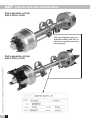
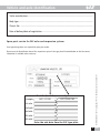
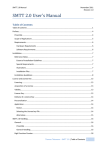
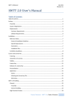
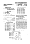
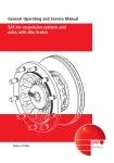
General Operating and
Service Manual
SAF suspension systems and
J-Series-axles with drum brakes
ILE
ALTE TS
N
I
G
I
R
R
nd O GINAL PA
u
E
C
I
ERVI
d OR
SAF S RVICE an
om
E
c
.
s
e
l
SAF S
-ax
.saf
w
w
w
Edition 01/2006
Service
Vehicle and axle identification
SAF suspension system
with J-Series axles
Axle type designation (Type) and
production number (Prod. No.) are
required for complaint processing
(see type plate).
SV11489GB Edition 01/2006 · Last updated 2006-01-31 · Amendments and errors reserved © SAF
SAF suspension system
with J-Series axles
GB
D 2
Vehicle and axle identification
Trailer manufacturer..................................................................................................................
Body type ..................................................................................................................................
Chassis No. ..............................................................................................................................
Date of delivery/date of registration ........................................................................................
Spare parts service for SAF axles and suspension systems
Exact type designations are required for spare parts orders.
Example:
Prod.-No. (Serial-No.)
0411121101
Type
RZT 12242/18C
1st axle
2nd axle
3rd axle
4th axle
5th axle
Enter the axle data from the SAF type plate
SV11489GB Edition 01/2006 · Last updated 2006-01-31 · Amendments and errors reserved © SAF
Please enter the identification data of the suspension system in the type plate illustrated below so that the correct
information is available when necessary.
3 GB
D
Contents
GB
Page
Identification of SAF axles ........................................................................................................................................2-3
SAF general safety instructions ....................................................................................................................................5
SAF general service instructions ..................................................................................................................................6
Tightening torques........................................................................................................................................................7
Service schedule
RZ 12242/18C, RZT 12242/18C, RZ 12242/20C, RZT 12242/20C..................................................................................8
General information
Check the brake setting................................................................................................................................................9
Slack adjuster ............................................................................................................................................................10
Tightening instructions for adjustable pivot bolt ........................................................................................................11
Semi-trailer tilt angle..................................................................................................................................................12
SV11489GB Edition 01/2006 · Last updated 2006-01-31 · Amendments and errors reserved © SAF
Adjustment of the air suspension system ride height ................................................................................................13
GB 4
Axle alignment ..........................................................................................................................................................14
General safety instructions
Please observe the following safety instructions in order to maintain the operational and road safety
of your SAF axles and suspension systems:
1. The wheel contact surfaces between the wheel disc and wheel hub and the wheel nut contact surface at the
wheel disc must not be additionally painted. The contact surfaces must be clean, smooth and free from
grease. Failure to observe this may result in the wheel coming loose. Any additional instructions of the wheel
manufacturer must also be observed.
2. Only the wheel and tyre sizes approved by the trailer builder may be used. The tyres must always have the
specified inflation pressure.
3. The brake systems of the tractor and the trailer/semi-trailer must be synchronised by means of a tractor/trailer
brake synchronisation not later than 5,000 km after the initial start of operation of the trailer/semi-trailer
in order to ensure a safe and uniform braking behaviour and uniform brake pad wear. Tractor/trailer brake
synchronisations should be carried out by appropriately qualified and equipped brake workshops.
The use of an additional braking system, such as a trailer anti-jackknife brake is forbidden by law on vehicles
with type approval after January 1999.
4. Before starting a journey, ensure that the maximum permissible axle load is not exceeded and that the load is
distributed equally and uniformly.
5. On trailers with air suspension, ensure that the air bags are completely filled with air before starting the
journey. Incompletely filled air bags may result in damage to axles, suspension, frame and superstructure and
impair road safety.
6. Ensure that the brakes are not overheated by continuous operation.
With drum brakes, overheating can result in a hazardous deterioration in the braking efficiency.
7. The parking brake must not be immediately applied when the brakes are hot, as the brake discs and brake
drums may be damaged by different stress fields during cooling.
8. Use the supports provided when loading and unloading in order to avoid damage to the axle.
9. Observe the operating recommendation of the trailer builder for off-road operation of the installed axles and
suspension systems.
The SAF definition of OFF-ROAD means driving on non-asphalted / non-concreted routes, such as e.g. gravel
roads, agricultural and forestry tracks, on construction sites and in gravel pits.
Off-road operation of SAF axles and suspension systems not designed for the purpose may result in damage
and hence to an impairment of road safety.
10. SAF axles and suspension systems require continuous care, service and maintenance in order to maintain
operational and road safety and to be able to recognise natural wear and defects in good time.
The daily inspection of the trailer for road safety before starting the journey is one of the driver’s obligations.
SAF recommends that at least the inspections and maintenance operations described on page 26 should be
carried out.
We recommend the use of original SAF spare parts.
A close-knit service network of SAF partner companies is available for the technical support of the SAF axles and
suspension systems and for the supply of original SAF spare parts (see rear cover or on the Internet under
www.saf-axles.com).
Updates will be published as necessary on the Internet under www.saf-axles.com.
SV11489GB Edition 01/2006 · Last updated 2006-01-31 · Amendments and errors reserved © SAF
With disc brakes, overheating can result in damage to surrounding components – in particular the wheel
bearings. This can result in a significant deterioration in road safety, e.g. failure of wheel bearings.
5 GB
SV11489GB Edition 01/2006 · Last updated 2006-01-31 · Amendments and errors reserved © SAF
General service instructions
•
Caution: After every wheel change, always retighten the wheel nuts to the prescribed torque after 50 km and
again after 150 km.
•
Check the brake lining thickness at regular intervals.
•
Carry out general visual inspections of the brakes, tyres and all suspension components at regular intervals and
check for proper attachment, wear, leaks, corrosion and damage.
•
Carry out regular visual inspections of the wheel bearing unit for grease leaks and axial clearance.
Wheel bearing grease change, see page 8.
•
Regularly check the camshaft for smooth return and the slack adjuster for proper function.
•
Lubricate the camshaft at regular intervals.
•
Inspect the brake drum for wear* and cracking at every brake lining change.
Minimum wear limits*, see page 8.
•
Replace the brake shoe return springs at every brake lining change.
•
Check the air suspension ride height at regular intervals in accordance with the trailer builder's specifications
and adjust as described on page 13.
•
On all units, check that the bolts of the U-brackets are tightened to the prescribed torques as described on page 7.
•
Carry out a general safety check in accordance with the statutory provisions.
•
We recommend the use of original SAF spare parts.
* We recommend that a general safety check is carried out when the minimum wear limit is reached.
GB 6
Tightening torques
Tightening torques for SAF leaf suspension system and J-Series axles
M14 105 Nm
M14 105 Nm
M24 600 Nm
M30 350 Nm
M48 1100 Nm
M30 350 Nm
M14 105 Nm
Strebenstangen-Gruppe verstellbar
adjustable torque arm kit
M30 350 Nm
M24 600 Nm
M30 350 Nm
M30 350 Nm
M14 105 Nm
Tightening torques for SAF air suspension system and J-Series axles
M24x2 (SW36)
400 Nm
M30 (SW46)
400 Nm + 120º
M22x1,5 (SW32) M20 (SW30)
580 Nm
180 Nm
M12 (SW19) 80 Nm
for steel plunger piston
Cut-screw
K100x40 (SW10)
20 Nm
for plastic plunger piston
Attention!
• Threads not to be oiled or greased!
• Pivot bolt on steel hanger brackets maintenance-free.
SV11489GB Edition 01/2006 · Last updated 2006-01-31 · Amendments and errors reserved © SAF
M30 350 Nm
M14 105 Nm
Strebenstangen-Gruppe starr
rigid torque arm kit
7 GB
Service schedule
Axle types
RZ 12242/18C, RZT 12242/18C, RZ 12242/20C, RZT 12242/20C
Grease specifications
Adjust wheel bearing clearance:
Tighten the WAF 85 axle nut to 150 Nm, turning the wheel hub
at the same time.
Turn back the axle nut by 2 1/2 holes of the lock washer.
Push on the lock washer and secure the axle nut with the
locking pin.
Tighten the lock nut to 400 Nm.
Check the running and rock of the wheel bearing.
The wheel must turn without resistance and no rock may be felt
at the wheel rim. Correct the adjustment, if necessary.
Replace the O-ring and fit the wheel cap.
Replace the brake shoe return springs at every brake pad change.
For wheel bearings:
SAF Part No. 5 387 0011 05
For camshaft:
SAF Part No. 5 387 0011 05
For axle stub end:
SAF mounting paste
SAF Part No. 5 387 0021 01
For ball in brake carrier:
Copper paste
SAF Part No. 5 387 0014 01
SV11489GB Edition 01/2006 · Last updated 2006-01-31 · Amendments and errors reserved © SAF
Brake
size
SAF Part No.
Brake lining
Brake drum / brake lining
Repair stages in mm
x 180
x 200
d0-420.0
3 057 9912 00
3 057 9912 10
3 057 9912 20
3 057 9913 00
3 057 9913 10
3 057 9913 20
Brake
lining
19.0
20.0
17.5
19.0
20.0
SAF Part No.
4 434 3828 00
3 301 0010 00
4 434 3822 00
3 434 3320 00
3 434 1036 00
3 349 1001 00
424.0
d2
2. Rep.-Stufe
2nd
oversize
422.0
d1
Rivet
Rivet
DIN 7338
Number per axle
d2-424.0
17.5
Assembly tools
Axle types 12242
Axle nut wrench
Puller for wheel hub
Universal puller for wheel hub
Fitting mandrel for wheel bearing and seal ring
Fitting mandrel for cassette seal ring
Brake shoe tensioner
GB 8
d1-422.0
420.0
424.0 mm
425.0 mm
Normal dimension 1st repair stage 2nd repair stage
SNF 420
1. oversize
Rep.-Stufe
1st
BRAKE SNF 420
Max. admissible brake drum machining diameter:
Max. admissible brake drum wear diameter:
Use only brake lining qualities recommended and approved by SAF!
Machine new brake linings to diameter + 0.3 mm of the brake drum.
When riveting on, observe the lining form (see instructions in the pack).
d0
Note during brake repairs:
Lubricate the camshafts, rotating the camshaft
through 360° several times.
Do not dismantle the wheel bearing unit.
Use a vacuum cleaner to remove brake dust.
Use of a high-pressure cleaner or liquid cleanser is
not permitted on the brake drum and brake hub.
Remove old grease from the stub axle and regrease.
Max. permissible axial backlash of hub unit:
0 - 0.20 mm
Normalmaß
nominal
size
Tighten axle nuts
8
8
8
8
8
8
80
80
80
80
80
80
B8 x 15
B8 x 15
B8 x 15
B8 x 15
B8 x 15
B8 x 15
General information
Check the brake setting
Adjustment of S-cam brakes with manual slack adjusters
The natural wear of the brake drum and brake lining necessitate frequent adjustment of the wheel brakes in order to
maintain the maximum stroke of the brake cylinders. In order to achieve good braking, it is essential to minimise the
clearance between the brake drum and brake lining. In order to check the clearance, the service brake is applied with
full pressure and the stroke of the brake cylinder checked. If the stroke at the yoke end is more than 2/3 of the maximum
cylinder stroke, the brake must be urgently adjusted. If the brakes are correctly adjusted, it should not be possible to
move the piston rod more than 15 mm by hand.
Turn the adjusting screw to the
right until the
brake shoes are firmly up
against the brake drum.
Turn the adjusting screw to
the left until
the free travel of the slack
adjuster (at 127 mm) is
approx. 10 - 15 mm.
Adjustment is performed at the
adjustment screw (WAF 19)
It must be possible to turn the
wheel freely without braking
(without scraping noises).
Special instructions apply for automatic slack adjusters (see adjustment procedure on the following
pages).
A = Angle must not exceed 90° at 1/2 stroke.
B = No contact permissible between slack adjuster and axle beam during emergency braking.
L = Observe piston rod length as per the SAF specifications.
SV11489GB Edition 01/2006 · Last updated 2006-01-31 · Amendments and errors reserved © SAF
No clearance between
piston and diaphragm
permitted in the rest
position.
9 GB
General information
Slack adjuster
Note when changing over from mechanical slack adjuster to automatic slack adjuster:
In order to avoid damage to the wheel brake, install only the automatic slack adjuster with the prescribed adjustment
gate and corresponding mounting point strap approved by SAF for the respective axle type.
Changes to the effective brake lever lengths are not admissible.
The field installation of automatic slack adjusters does not require type approval so that no inspection by the technical
inspection authorities (TÜV) is necessary.
Technical information on SAF spare part numbers and correspondence of slack
adjusters and axle types can be obtained from the SAF service partners.
SV11489GB Edition 01/2006 · Last updated 2006-01-31 · Amendments and errors reserved © SAF
From April 2004
TGL slack adjusters (14 mm hole diameter)
Manufacturer: Guangzhou Runhope Automotive Parts Co. Ltd.
From September 2005
QC slack adjusters (12,75 mm hole diameter)
Manufacturer: Wan Xiang Qianchao Co. Ltd.
GB 10
General information
Tightening instructions for adjustable pivot bolt
Pretightening 400 Nm
Use Torque wrench
Angle tightening 120°
Use impact wrench or extend
lever to 2.5 m
Bolt head always on the eccentric
washer side.
Marking for angle tightening
Visual inspection
SV11489GB Edition 01/2006 · Last updated 2006-01-31 · Amendments and errors reserved © SAF
Attention:
Tightening always within the
specified ride height range!
No paint residues between
eccentric/thrust washer and hanger!
11 GB
General information
Semi-trailer tilt angle
Ride heights
Adjust the ride height of the air suspension axles to the permissible range indicated in the corresponding SAF
documents.
With single axles, allow for a minimum suspension travel of 60 mm.
For trailers with multiple axles, allow for a minimum suspension travel of 70 mm.
SV11489GB Edition 01/2006 · Last updated 2006-01-31 · Amendments and errors reserved © SAF
Exception:
For multi-axle trailers with lift axles, the minimum suspension travel at the lift axle should not be less than 100 mm
in order to ensure an adequate ground clearance.
GB 12
General information
Adjustment of the air suspension system ride height
Air suspension valve
As standard, SAF air suspension axles and system require only one air suspension valve.
The air suspension valve controls the air bag pressure in relation to the trailer load in order to maintain a constant
ride height in every load condition.
The air suspension valve is fastened to the trailer frame with screws and connected to the axle via the pivot joint
(valve lever and adjustment pipe). On triple-axle trailers, the system is generally connected to the middle axle (normally
in the middle of the axle), and on twin-axle trailers to the rear axle. In special cases (e.g. large trailer tilt angle), the air
suspension valve can be installed in the rear axle.
Installation
The valve lever should be at least 200 mm long and is horizontal when the trailer is in the driving position.
As a function check, move the lever down slightly. Air must now escape via the venting cap into the atmosphere. If air
flows into the air bags when the lever is pushed down, the valve lever has to be turned through 180°. For this the valve
lever has to be disconnected. The ride height is set by adjusting the adjustment pipe in the fulcrums and by turning the
lock nuts.
The adjustment must be carried out with the trailer standing on level ground. It can be carried out with the trailer either
empty or loaded.
Note
For a final check, the air suspension system should be lowered to the suspension stop or raised to the limit (shock
absorbers, stop ropes, air bag length). During this process, the specified angle between valve lever and adjustment pipe
must not be exceeded in order that the valve lever does not move in the wrong direction.
SV11489GB Edition 01/2006 · Last updated 2006-01-31 · Amendments and errors reserved © SAF
For trailers with axle lifting system, the axle to which the system is connected depends on the axle to be lifted.
13 GB
Axle alignment
In order to compensate for production tolerances, an axle alignment and, if necessary, a correction should be carried out.
The maximum permissible deviations (tolerances) of the alignment values are specified by the tyre manufacturer.
The maximum possible wheelbase correction per axle is ± 6 mm.
Conventional adjustment
Determine the lengths of the diagonals A - C and A - F for the middle axle (reference axle) by comparison measurements,
observing the tolerances.
Check the wheelbases B - C and E - F for the front axle and C - D and F - G for the rear axle and correct, if necessary,
observing the tolerances.
Optical adjustment
SV11489GB Edition 01/2006 · Last updated 2006-01-31 · Amendments and errors reserved © SAF
Observe the operating and setting instructions of the measuring system manufacturer.
Calculation of the toe-in and
toe-out values:
A1 - B1 (mm)
=S
A (m)
S = positive value = Toe-in
S = negative value = Toe-out
Notes
1. In order to avoid tyre wear, we recommend that an axle alignment is performed at regular intervals.
2. We recommend the use of an optical measuring system for carrying out the axle alignment.
3. For alignment, only the centres of the middle of the wheel cap or the middle of the axle stub end are of interest
as reference points.
4. Possible causes of deviations in the axle alignment are:
• Loose U-bolts
• Wear of the spring guide bearing
• Deformation of the axle assembly components due to improper use
GB 14
SV11489GB Edition 01/2006 · Last updated 2006-01-31 · Amendments and errors reserved © SAF
NOTIZEN/NOTES/NOTE
15 GB
Australia
HDTE - Heavy Duty Transport
Equipment Pty. Ltd.
91 Dohertys Road
AUS- Altona North Victoria 3025
Brazil
SAF "Do Brasil"
Rua Margarida de Campos 77
13076-240 Prq. Taquaral
BR- Campinas
China
Jinan SAF ALKO Axle Co. Ltd.
No. 9 Xianwen South Road, Jinan
RC-250101 Shandong Province
China
SAF AL-KO Vehicle Technology Yantai Co. Ltd.
Guangchang North Road 1, Laishan
RC-264003 Yantai, Shandong
Japan
Shinko Boeki Co., Ltd.
Shibuya Central Building
3-14, Udagawa-cho,
J-150-0042 Shibuya-ku, Tokyo
SV11489GB Edition 01/2006 · Last updated 2006-01-31 · Amendments and errors reserved © SAF
New Zealand
Transport Specialties Limited
Cnr Kerrs and Ash Roads, Wiri
South Auckland Mail Centre
NZ- Auckland
Russia
SAF-INTCOM
Dolgoprydny, pos. Sheremetevsky
Novoe Shosse 1
RUS-141050 Moskovskay Oblast
South Africa
SAF Axles South Africa (Pty) Ltd
47 Oxford Road
ZA-2196 Forest Town
South Korea
JB Enterprises, Korea
Namdong-Gu, Guwall 1-Dong, 201-29
Gumhwa Office Suite 603
ROK-405-827Incheon
Mr. Craig Wallace
Tel.: +61 3 9369 0856
Fax: +61 3 9369 1681
[email protected]
www.hdte.com.au
Mr. Johann Strasser
Tel.: +55 19 32954214
Fax: +55 19 32953270
[email protected]
www.saf-axles.com
Mr. Dian Bo Li
Tel.: +86 1360 640 2297
Fax: +86 531 8870352
[email protected]
www.saf-alko.com
Mr. Dian Bo Li
Tel.: +86 1360 640 2297
Fax: +86 535 672 7797
[email protected]
www.saf-alko.com
Mr. Yutaka Nozawa
Tel.: +81 3 34630941
Fax: +81 3 34631407
[email protected]
www.saf-axles.com
Mr. Bruce Munro
Tel.: +64 9 9807322
Fax: +64 9 9807306
[email protected]
www.transpecs.co.nz
Mr. Emil Nizamov
Tel.: +7 095 7825082
Fax: +7 095 579 94 00
[email protected]
www.saf-intcom.ru
Mr. Willem Brits
Tel.: +27 11 646 0292
Fax: +27 11 942 1778
[email protected]
www.saf-axles.com
Mr. M. S. Kim
Tel.: +82 32 4220301
Fax: +82 32 4220091
[email protected]
www.saf-axles.com
www.saf-alko.com · www.saf-axles.com
Jinan SAF ALKO Axle Co. Ltd. · No. 9 Xianwen South Road, Jinan · RC-250101 Shandong Province
SAF AL-KO Vehicle Technology Yantai Co. Ltd. · Guangchang North Road 1, Laishan · RC-264003 Yantai, Shandong