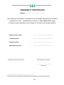
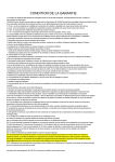
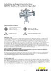
1
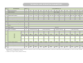
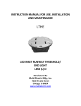
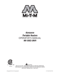
METAL ELEMENTS AND BOILER MANUFACTURER
28-100 Busko-Zdrój,
Owczary, ul. Przemysłowa 3
s
SAS MIECZYSŁAW
Phone: +48 41 378 46 19, Fax +48 41 370 83 10
TECHNICAL DOCUMENTATION OF
WATER CENTRAL HEATING BOILER OF
SAS AGRO-ECO TYPE
SAS
A GRO -E CO
1
INDEX
Conformity Declaration
3-4
Ecological Certuficate
5
1.
Introduction
6
2.
Boiler destination
6
3.
Boiler construction description
7
4.
Technical and operation parameters
10
Boiler construction scheme
11-12
5.
Fuel
13
6.
Guidelines for boiler installation
14
6.1
Requirements for boiler-room
15
6.2
Boiler installation
15
6.3
Chimney connecting
16
6.4
Central heating system connecting
17
6.5
Electrical system connecting
18
7.
Guidelines for operating and maintenance
18
7.1
Filling with water
18
7.2
Boiler fire-up and operation
19
7.2.1 Firing up and functioning of a boiler in automatic mode
19
7.2.2 Firing up and functioning of a boiler in emergency mode
21
7.3
Boiler cleaning
21
7.4
Operation ending
22
8.
Safe operation conditions
22
9.
Troubleshooting
23
10. Protections
24
11. Delivery conditions
25
12. Boiler utilization
25
13. Terms of warranty
26
Service repairs
28
Warranty card
29
-2-
-3-
-4-
-5-
1. INTRODUCTION
Dear purchaser and user of SAS AGRO-ECO boiler. This User Manual contains all
information required for ensuring of energy saving, safe and long operation of
purchased boiler.
Please read this Manual carefully before boiler installation and running.
2. BOILER DESTINATION
SAS AGRO-ECO boilers equipped with fuel storage bin and automatic feeder are
destined for central heating installations working in open system* with gravitational or
forced water circulation. Installation must be protected in accordance with PN-91/B-02413
standard. Boilers are recommended for single houses, trade service and gastronomic
pavilions, workshops, etc, on which heat distribution network water temperature is not
higher than 90°C and working pressure is not higher than 0.15 Mpa. Depending on boiler
power, required combustion gas draught after boiler is equal 15÷45 Pa.
Boiler can be also connected to hot water installation using heat exchanger.
The basis of selection of boiler for building should be heat balance prepared in
accordance with valid PN-B-02025:2001 standard.
Boilers of SAS AGRO-ECO type
installed in accordance with this documentation are not subject for Office of Technical
Inspection acceptance.
_____________________________
* Heating system installation must meet requirements of PN-91/B-02413 and BN-71/8864-27 polish standards
regarding protection of water heating devices working in open system and collect water bin of open system.
-6-
3. BOILER CONSTRUCTION DESCRIPTION
SAS AGRO-ECO type boiler is a low – temperature boiler for central heating. Boiler is
adapted for highly – efficient, fully automatic combustion of biomass supplied as
granulated product (called also „pellets”) and grains. Basic elements of boiler are showed
on the illustration.
Boiler frame is made from welded steel sheets. The water jacket is in form of cuboid
with double walls and separating water baffles. Combustion chamber is mounted under
highly efficient convectional heat exchanger.
The unit’s framework based on the three-way convective channel structure makes
the most of exhaust heat to heat the water. Upper part of combustion chamber is
covered by water jacket.
Combustion gases are carrying away to chimney by smoke conduit (pos 15), located
upper part of boiler.
Cleanout hole door, fuel loading door and double door, used as a furnace and ash
box door are located on the boiler front side. Front cleanout hole door (pos 2) and fuel
loading door (pos 3) enable access to combustion chamber in order to carry out a
maintenance activities and boiler convectional ducts periodical cleaning. Door can also
be used for manual (emergency) fire-up of boiler in automatic fuel loading mode and is
used as a fuel loading door for fuel loading in “conventional” mode. Ash box door (pos
4) is used as a furnace and ashtray door. In ashtray door bottom part flap (pos 5) is
located. Flap is used for air intake dosage for combusting process. Lateral cleanout hole
door (pos 7) allows removing ash produced during combusting process.
Hot water connector pipe (pos 14) is welded to the heat exchanger upper side.
Return water connector pipe (pos 18) is located on the lateral, bottom side of heat
exchanger. Blowdown connection (pos 19) is also located on the boiler lateral wall.
Charging hopper (fuel storage bin – pos 13), feeder drive mechanism (pos 10) and
downcast ventilator (pos 8) are located on the boiler rear side.
Heat exchanger is covered with insulating material (mineral wool) which filling space
between heat exchanger and boiler enclosure.
Characteristic feature of SAS AGRO-ECO type boilers is automatic, highly –
efficient, self – cleaning furnace, combusting only fuel portion necessary to reach
-7-
temperature defined by user on the temperature controller. Furnace elements exposed
to high temperature are made from heat – resisting steel and ceramic materials.
Applying of ceramic panels in furnace construction allows to ensure optimal conditions
for biomass combustion (corn combustion optimal temperature is equal 1200°C),
increasing furnace efficiency and furnace life – time.
Fuel is loading automatically from storage bin through feeding screw. All processes
leading to fuel combusting with air supplied by downcast ventilator located under burner
enclosure (pos 8) takes place on the combustion chamber fire grate. Blowed air is
distributed in air chamber. Primary air is delivered under fire grate; overfire air is blowed
into combustion zone through the nozzles system, located in ceramics panels.
Depending on fuel applied, electronics circuit controls air volume delivered by downcast
ventilator
In order to ensure comfortable operation boiler is equipped with incandescent spiral
used for self-acting fuel ignition. Thanks to automatic fuel ignition and fire maintaining
system after reaching of defined temperature boiler can operate even if demand for
thermal power is very small. Boiler can be operated continuously and is adopted for cooperation with hot water storage bin used in summer time.
Controller with build – in microprocessor automatically controls feeding screw,
downcast ventilator, incandescent spiral and furnace cleaning mechanism operation.
Small, non-combustible portion of fuel (ash) remaining after biomass combustion in
last combustion stage is carry away to ash box chamber and stored on the removable
ash tray (pos 6). Ashtray should be cleaned periodically. Ash reminder from biomass
combustion process can be successfully used as a full value, ecological fertilizer for soil
refining.
=============================================================
Efficient boiler furnace allows to combust only fuel portion, which is necessary to
maintain temperature set by user on the temperature controller. Controller measures
constantly water temperature in boiler and based on the results controls the boiler
working elements operation. Controller operates also circulating pump of central heating
-8-
and hot water storage bin.* Boiler controller is also adopted for operation with any
controller of room temperature.
The advantage of boiler operation is simple servicing which requiring only refueling
of storage bin (charging hopper must be refueled once per 1-3 days, depending on
weather conditions and building thermal insulation) and ash removing from ashtray.
There is no need to damp a fire. After light-up, boiler not requiring constant servicing
and can operate continuously within whole heating period except periodical, scheduled
maintenance activities. Boiler can also operate with hot water storage bin beyond
heating season.
Thanks to fuel feeder driven by gear – motor, self-cleaning furnace and electronics
temperature controller operation of SAS AGRO-ECO type boiler is operated
automatically (continuous operation).
Boiler is adopted for operation in “emergency burning” mode which is very useful in
case of no power or feeder / ventilator failure. In this mode boiler operates using natural
gas draught and electric energy is not required. Combustion process can be adjusted
manually using inflow air adjusting screw mounted in air dosing flap (pos 5).
In order to ensure operation safety, SAS AGRO-ECO boiler is equipped with multilevel protection system. Boiler is protected against flame back to storage bin through
fuel feeder (fuel duct temperature sensor) and boiler overheating (thermo breaker). In
case of fuel feeder blocking, movable grate-bar driving mechanism damage or flame
decay in heating chamber boiler will be switched-off automatically.
In case of power supply cutting, current operation state and all controller settings are
stored in memory and thanks to that after power – on boiler is started automatically and
defined temperature is reached.
* You will find a detailed description of structure, operation and service of the controller in an enclosed
specifications sheet „CONTROLLER OPERATING MANUAL”.
-9-
TECHNICAL AND OPERATION PARAMETERS
No.
Parameter
Unit
SAS AGRO-ECO
Boiler power
kW
17
23
29
36
42
48
58
68
78
90
100
2.
Boiler heated surface
m2
1.5
2.0
2.5
3.0
3.5
4.0
5.0
6.0
7.0
8.0
9.0
3.
Boiler efficiency
4.
Fuel consumpcion*
5.
Load chamber capacity
6.
Boiler water capacity
kg/h
dm3
kg
l
1,9
120
~75 ÷ 85
90
2,6
120
~75 ÷ 85
100
3,3
140
~90 ÷ 100
120
4,1
180
~115 ÷ 130
140
4,8
210
~135 ÷ 150
160
5,5
230
~145 ÷ 165
190
6,6
280
~180 ÷ 200
260
7,2
320
~200 ÷ 240
350
8,3
360
~240 ÷ 260
420
9,6
380
~260 ÷ 280
510
10,7
410
~280 ÷ 310
620
7.
Boiler weight (without water)
kg
440
490
520
610
650
780
890
930
1100
1220
1310
8.
9.
Required chimney draught
Exhaust temperature
°C
90 ÷ 210
10.
Maximal allowable opperating pressure
bar
1,5
11.
12.
°C
85
°C
60 ÷ 80
13.
Maximal allowable working temp.
Reccomended heating water working
temp.
Minimal return water temp.**
14.
Power supply
15.
Power consumption
16.
Dimensions
1.
%
87,7 ÷ 88,8
mbar
0,30
0,45
°C
55
V/Hz
~230 / 50
W
0,55
190
210
260
360
(+ 900 at start burning)
( + 900 at start burning)
(+ 900 at start burning)
(+ 900 at start burning)
A
mm
1490
1590
1590
1660
1780
1850
1900
1990
2090
2190
2240
A1
mm
840
940
940
1020
1020
1090
1140
1180
1180
1280
1280
B
mm
550
550
620
620
670
670
740
740
780
780
780
B1
mm
450
450
520
520
570
570
640
640
680
680
680
H
mm
1590
1590
1630
1630
1630
1630
1630
1740
1810
1810
1920
H1
mm
1420
1420
1420
1440
1520
1540
1540
1610
1610+c*
1610+c*
1720+c*
C
mm
260
360
360
430
430
450
500
500
500
590
590
C1
mm
180
180
180
180
180
250
250
250
250
280
280
D
mm
520
520
520
520
620
620
620
650
650
650
650
mm
∅160
∅180
∅200
∅200
∅220
∅220
∅250
Ø 260
Ø 270
Ø 280
Ø 300
17.
18.
19.
Smoke conduit diameter
20.
Min. chimney dimensions / diameter
Connector pipe diameter(supply/return)
"
Min. chimney height
m
6
7
cm x cm
18x18
Ø210
20x20
Ø220
mm
G 1½
G2
G 2½
8
21x21
Ø240
9
22x22
Ø250
25x25
Ø280
10
25x25
Ø280
26x26
Ø320
11
26x26
Ø320
28x28
Ø360
12
28x28
Ø360
29x29
Ø380
* when working at average load (50% or rated power)/ rated load
**if manufacturer recommendations regarding heating water temperature ranges are not observed, boiler must be obligatory connected to central heating system equipped with tree- or four- ways valve, protecting
against so called “low temperatures corrosion”
10
C* handle use to transport a boiler ( dimension 150 mm)
BOILER CONSTRUCTION SCHEME OF SAS AGRO-ECO TYPE (17 - 58 kW)
1.
2.
3.
4.
5.
6.
boiler cover (body)
washout door
fuel load door
ash box door
air intake dosage flap
ash box
7.
8.
9.
10.
11.
12.
lateral washout hole
blowing fan
grate drive mechanism
feeder drive mechanism
ceramic heater
ceramic panels
- 11 -
13.
14.
15.
16.
17.
18.
fuel storage bin
hot water connector pipe
smoke conduit
safety valve
controller (panel)
return water connector pipe
19.
20.
21.
22.
blowdown connection
air regulator knob
exhaust temperature sensor
handles grate assembly
replacement
23. connecting strip
24. air draft regulator
BOILER CONSTRUCTION SCHEME OF SAS AGRO-ECO TYPE (58-100 kW)
1.
2.
3.
4.
5.
air intake dosage flap
ash box door
ash box
boiler cover (body)
handles grate assembly
replacement
6. ceramic panels
7.
8.
9.
10.
11.
12.
fuel load door
washout door
safety valve
smoke conduit
exhaust temperature sensor
fuel storage bin
- 12 -
13.
14.
15.
16.
17.
18.
hot water connector pipe
controller
return water connector pipe
lateral washout hole
blowdown connection
feeder drive mechanism
19.
20.
21.
22.
ceramic heater
grate drive mechanism
blowing fan
air regulator knob
5. FUEL
Problem-free operation of SAS AGRO-ECO type boiler equipped with automatic
burner and fuel feeder depends on adequate fuel applying or adaptation of boiler
operation to available fuel.
Proper selection of kind of biomass guarantees not only fuel saving (thanks to
effective fuel combustion) but also makes possible to save time required for boiler
servicing. Kind of bio fuel and also applied bio fuel humidity are very important
parameters, which must be taken into account to reach adequate boiler heating results.
SAS AGRO-ECO type boilers combusting miscellaneous fuels – e.g. vegetable
products, what gives many possibilities for user. Primary fuel is granulated wood – so
called pellets* (both, from sawdust, tree bark, energetic willow and e.g. rape straw). As
a secondary fuel – combusted with good results – various grains can be applied, e.g.
oat, rye, barley, wheat, charlock, maize, lupine. Other fuels as e.g. willow chips (less
than 20 mm of length and less than 15% of humidity), dry stones (e.g. from cherry, etc.)
are also allowed. Low quality grains (e.g. from plantations located on polluted areas or
from trees with bacteriosis) can also be applied as a fuel. Because furnace is equipped
with movable fire-bars mechanism, fuels producing residues can be applied.
OTHER COMBUSTIBLE MATERIALS ARE NOT ALLOWED FOR USE WITHOUT
WRITTEN PERMISSION FROM MANUFACTURER.
______________________
* Diameter: 6÷8 mm, length 20÷30 mm. Please do not apply fuel with granulation other than stated
because it can cause feeder operation problems. In particular, during fuel loading or refueling it is
mandatory to check if some unwanted objects or stones are not present. Presence of this kind of objects
may cause locking of feeder mechanism.
13
Basic parameters of granulated product (pellets) for SAS AGRO-ECO type boilers:
Table 2
Granulated product
diameter
Granulated product
length
Calorific value
Humidity
Ash percentage
Sulphur percentage
Specific gravity
ø = 6 ÷ 8 mm
10 ÷ 30 mm
16 000 ÷ 19 500 kJ/kg
8 ÷ 10 %
0,6 ÷ 1,0 %
< 0,1 %
0,65 ÷ 0,75 kg/dm3
ATTENTION: Storage bin should be filled with water-free fuel, without excessive
quantity of small fraction or foreign matter!
6. GUIDELINES FOR BOILER INSTALLATION
Boiler installation must be realized by qualified staff holding authorization for this
kind of activity (specialized person, trained for this kind of activity, holding authorization
for maintenance and repair works). Fitter is obligated to become familiar with product,
product operation and protection circuits operation manner. Before boiler connecting to
central heating system it is mandatory to become familiar with this documentation.
- 14 -
6.1. REQUIREMENTS FOR BOILER-ROOM
Boiler room where central heating system boiler will be installed must meet
requirements of currently valid detailed regulations of destination country (e.g. PN-87/B02411 for Poland).
•
boiler-room must be located as centrally as possible in relation to heated rooms,
boiler should be installed very close to chimney;
•
boiler-room entry door should be opened outwards and must be made from nonflammable materials;
•
boiler-room should be equipped with supply ventilation in form of ventilating duct
with section not smaller than 50% of chimney section, but not smaller than 21 x
21 cm; outlet must be localized at the rear side of boiler-room. Absence of
supply ventilation or ventilation choke may cause smoking or impossibility to
reach higher temperature.
•
boiler-room should be equipped with exhaust ventilation, located under room
floor. Section of duct must not be smaller than 25% of chimney section, but not
smaller than 14 x 14 cm. Exhaust ventilation is destined for removing of harmful
gases from boiler-room).
ATTENTION:
It is not allowed to apply mechanical exhaust ventilation. Day and artificial
lighting should be available.
6.2. BOILER INSTALLATION
A special foundation is not required for boiler installation. It is recommended to install
boiler on the 2 cm height concrete footpace, but installation directly on the fire-resisting
floor is also allowed. Boiler must be located on such way, which makes possible easy
- 15 -
and safe furnace servicing, fuel loading and boiler cleaning. Very important point is to
keep suitable distance (min. 0,6 m) between boiler rear side and boiler-room wall.
6.3. CHIMNEY CONNECTING
Chimney duct construction and boiler connecting to chimney must meet
requirements of currently valid detailed regulations of destination country (e.g. Decree
of Infrastructure Minister dated April 12, 2002, Government bulletin number 75).
Boiler must be connected directly to chimney using smoke flue in form of wrought
pipe (allowable temperature of pipe must be higher than 400°C). Pipe diameter must
makes possible realization of tight connection between pipe and smoke conduit outlet.
Smoke conduit and chimney connection place must be sealed very carefully.
Height and section of chimney and realization precision are key factors for proper
boiler operation and because of that they should ensure maintaining of required
chimney draught.
Calculating of chimney height and section for boiler power should be realized
according to requirements of currently valid detailed regulations of destination country.
Table of chimney height and section recommended by manufacturer in relation to
boiler power.
If there is no possibility to ensure recommended chimney parameters and problems
with chimney draught appearing (incorrect boiler operation) it is recommended to install
waste gases exhaust ventilator or chimney cowl with built-in ventilator, which helps to
reach proper draught and draught stabilization.
Because waste gases from boiler should have reflection possibility, chimney must be
constructed from boiler-room floor level. Cleanout hole with hermetic closing should be
installed on the chimney bottom side.
In order to avoid reverse draught, chimney duct must be minimum 1,5 meter higher
than roof ridge. Chimney operation correctness should be checked and confirmed by
authorized chimney - sweep minimum once per year.
BEFORE BOILER START-UP CHIMNEY SHOULD BE BURNED !
It is strongly recommended to apply chimney insert made from stainless steel. In
case of long-lasting low temperature keeping in boiler applying of chimney insert
- 16 -
is mandatory. Keeping the low temperature in boiler causing emission of wet waste
gases. It can be a reason of moisture and corrosion of chimneys made from brick.
CHIMNEY OPERATION CORRECTNESS SHOULD BE
CONFIRMED BY AUTHORIZED CHIMNEY SWEEP.
6.4. CENTRAL HEATING SYSTEM CONNECTING
Boiler should be connected with central heating system using screw joints. Protection of
heating installations working in open system should be realized according to requirements
of currently valid detailed regulations of destination country (e.g. PN-91/B-02413 for
Poland). Volume of collect water bin should be equal minimum 4% of volume of water
flowing in heating installation.
ATTENTION: It is not allowed to install any valve on the ascent or downcomer tubes
and water circulating tube. Tubes and collect water bin should be protected against water
freeze.
SAS AGRO-ECO type boilers may work with gravitational or forced water circulation.
Differential valve should be mounted on supply / return tube if circulating pump is used in
installation. In case of electric power cut-off or pump damage valve will open automatically
and circulation will work in gravitational system.
ATTENTION: It is recommended to connect boiler to heating installation equipped with
three- or four - way valve. The advantage of proposed boiler connection method is boiler
protection against low temperature corrosion. Thanks to that boiler life – time will be longer.
In case of not observing manufacturer recommendations regarding maintaining of
defined heating water temperature ranges (defined in Table
TECHNICAL AND
OPERATION PARAMETERS, mainly long-lasting water low temperature keeping below
55°C) boiler must be connected to heating installat ion equipped with three- or four – way
valve which protects boiler against „low temperature corrosion”.
- 17 -
6.5. ELECTRICAL SYSTEM CONNECTING
Boiler – room should be equipped with 230V / 50Hz electrical system realized
according to requirements of currently valid detailed regulations of destination country.
Electrical system must be terminated with wall outlet with ground contact. Defective
electrical system may cause controller damage and user electric shock. Extension cords
are not allowed to use.
Controller and other actuators are supplied with 230 V voltage and because of that
all connections can be realized only by authorized person (authorized electrician).
Power cords for other devices supplying must be kept away from boiler elements, which
becomes hot during boiler utilization (cover of upper cleanout opening, smoke conduit,
door).
7. GUIDELINES FOR OPERATION AND MAINTENANCE
7.1. FILLING WITH WATER
Boiler and installation filling with water should take place by boiler blowdown connector.
In order to remove air from installation filling must be conducted very slowly. Water
outflow from overflow pipe means complete installation filling.
It is recommended to loose screw joint on boiler and installation connection place (on the
hot water connector pipe) when filling with water. On the water outflow moment screw joint
should be tightened.
ATTENTION: Filling with water during boiler operation, mainly when boiler is very
hot is inadmissible and forbidden. It can cause boiler damage or crack!
After heating season water shouldn’t be drained from installation and boiler. If required
water is drained after cooling via blowdown connector to sink or floor drain.
- 18 -
7.2.BOILER FIRE-UP AND OPERATION
Before fuel fire – up it is mandatory to check installation filling with water. Water can’t be
frozen. It must be checked also if there is no water leakage on boiler or screw joints. Before
first boiler start – up chimney must be burned.
Person who servicing boiler must be aware about that some boilers surfaces are hot
and before touching it is mandatory to wear protective gloves!
Safety goggles also should be used.
7.2.1. BOILER FIRE-UP AND OPERATION IN AUTOMATIC MODE
Electrical fire - up
Thanks to build – in incandescent spiral burner fire-up in SAS AGRO-ECO type boiler is
realized automatically. In order to run boiler (furnace fire-up) it is required only to activate
“IGNITION” function in controller menu.
In fire-up mode controller operates fuel feeder – fuel is delivered at fire grate, in the
same time electrical ignition is started. During fire-up controller verifies process by constant
measurement of waste gases temperature. When flame appears in furnace electrical heater
is off and boiler is switched to operation mode. Volume of air delivered by downcast ventilator
and fuel quantity delivered to furnace is adjusted automatically according to defined, optimal
parameters specified for particular fuel type (service parameters).
After single fire-up boiler operates with no service and combustion process go on
continuously. Further boiler service requiring only storage bin refilling and ash removing
from ashtray. During fuel loading to charging hopper special attention must be pay – bigger
pieces of some foreign matter or stones can’t be present on fuel because they can cause
feeder blocking!
Controller settings should be defined depending on temperature outside of building and
quality of used fuel. For more information please read controller service manual delivered
with this documentation (chapter “Boiler operation parameters programming”).
- 19 -
Depending on weather conditions regulation of specific flame output and boiler thermal
power should be changed by regulation of temperature of water out flowing from boiler (if
three – or four – way valve is used, then regulation damper position should be change).
Controller operates also circulating pump of central heating system (if heating
installation is equipped with circulating pump).
It is not recommended to open any door during boiler operation because it can cause
waste gases withdrawal to charging hopper. When fire-up, smoking to boiler-room or boiler
wetting may appear. After boiler and chimney duct heat up mentioned above effects should
abate.
In central heating system demand for warmth is changing together with external
conditions, it means with daytime and ambient temperature. Value of temperature of water
out flowing from boiler depends also on building thermal characteristic – mainly materials
used for construction and insulation material characteristics are important.
Manual fire-up
If burner fire-up using incandescent spiral fails (error message: „UNSUCCESSFUL
ATTEMPT TO START FIRE (IGNITION FAILURE)) there is a possibility of spiral damage.
In this situation following points must be checked: 1° Does charging hopper is filled with
fuel? Some unwanted object does not block does gear?2°Does furnace is not filled with
excessive quantity of ash, which preclude fuel ignition from heater? If heater is damaged,
burner must be run in manual fire-up mode () :
1. Furnace must be cleaned from heat and soot, burner controller must be
off.
2. In manual operation mode fuel must be loaded to fire grate
3. Fuel must be sprinkled with other flammable fuel, wait till percolate
4. Fire-up
5. Run the controller and select “IGNITION” function
Person who servicing boiler must be aware about that some
boilers surfaces are hot and before touching it is mandatory to
wear protective gloves!
- 20 -
7.2.2. BOILER FIRE-UP AND OPERATION IN EMERGENCY MODE
Before fire-up, fuel-loading door (pos 3) must be opened, cleanout door (pos 2) and ash
box door (pos 7) should be fully closed. Substitute fire grate (pos 22) should be placed
inside of furnace chamber.
In order to protect against waste gases withdrawal to charging hopper in
emergency mode (using substitute fire grate) it is recommended to partially fill the
storage bin (pos 13). This will also protect against smoking from charging hopper.
Fire-up should take place slowly, initially squeezed sheets of paper and wood should be
used. Thin hard coal portion should be added later. When hard coal portion kindle – up, a
little bit bigger hard coal portion should be added. When this portion is kindled, after closing
the double door furnace chamber can be filled with fuel via fuel loading door. Next air
dosing flap in double door position should be set using adjusting screw in order to reach
required caloric effect and required temperature.
In case of fire in boiler extinguish, furnace must be cleaned, boiler ducts must be
ventilate and fire-up must be started again.
During normal operation in “traditional combusting” mode combusting process consist
in periodical refueling in furnace chamber. Single refueling in case of emergency mode is
enough for few hours of boiler operation, depending on reached boiler power.
7.3.BOILER CLEANING
In order to ensure economical fuel consumption and reach boiler thermal power and
efficiency it is mandatory to keep clean boiler combustion chamber and convectional ducts.
In combustion chamber special attention must be pay for periodical cleaning of micro –
gaps in automatic furnace panel.
Convectional ducts, on which volatile ashes creating layers must be cleaned
systematically every 3 – 7 days. This is very important in case of boiler operation in
“traditional combusting” mode. Boiler is equipped with special tools for this purpose.
Front cleanout door (pos 2) and fuel loading door (pos 3) makes possible to clean
convectional ducts. Additionally, air chamber located on the boiler rear side must be also
- 21 -
cleaned periodically because ash flowing from automatic furnace panel accumulates in this
area. Lateral cleanout hole (pos 7) is destined for this cleaning.
Cleaning of chimney duct is also critical for proper boiler operation.
7.4.OPERATION ENDING
After heating season, or in case of other scheduled boiler stopping, loaded fuel portion
should be burnt. After fire dump all residues of combusted fuel must be removed, boiler
should be cleaned and maintenance activities should be performed. Internal furnace
chamber baffers and all movable components should be lubricated with oil. Mechanism that
is used for fuel delivering to furnace chamber must be protected during boiler non-operating
time (horizontal sideways lubrication).
After heating season water shouldn’t be emptied from installation and boiler. In case of
emergency boiler damping hot fuel must be removed to tin boxes and carry out outside
boiler-room. It is also possible to spill incandescent fuel with sand.
ATTENTION: Fuel extinguishing with water in boiler-room is forbidden!
8. SAFE OPERATION CONDITIONS
In order to ensure safe boiler operation following rules must be observed:
•
boiler and installation must be maintained in good technical condition. Special
attention must be pay to central heating installation leakproofness and door and
cleanout holes closings leakproofness,.
•
keep boiler-room clean, do not store any objects not related with boiler servicing,
•
on the wintertime do not switch off heating. If boiler is not used, water can froze in
installation or in part of installation, freeze-up of overflow safety outlet pipe is very
dangerous; it can cause boiler destroying,
- 22 -
•
usage of petrol, kerosene, dissolvent, or similar substances for boiler fire – up is
forbidden because it may cause explosion or user injury,
•
in case of installation failure and lack of water in boiler, water can’t be refilled
when boiler is hot because it can cause boiler failure,
•
all boiler defects should be repaired immediately.
Boiler must be cleaned regularly from soot and soot substances – each sediment
on the convectional ducts walls disturbing heat absorption from heat exchanger –
boiler efficiency is lower and fuel consumption is higher.
9. TROUBLESHOOTING
PROBLEM
REASON / SYMPTOM
SOLUTION
flues impurity
no fresh air inflow to boiler-room
inadequate fuel applied
Low boiler
calorific
effect
wrongly calculated boiler power in
relation to building surface
incorrect design and realization of
central heating system
incorrect operation of controller,
ventilator or feeder
Smoking
clean – up flues via cleanout hole
door
check supply ventilation condition
in boiler-room, improve airflow
apply fuel with proper quality
(please read “Fuel” chapter).
insufficient chimney draught
(if chimney draught is too weak
smoking from boiler may appear,
mainly when boiler starts-up)
flues impurity
define new controller settings
according to weather conditions
and kind of fuel, mainly feeder
operation time and fuel delivery
pauses should be changed
if controller doesn’t work correctly,
please refer to controller user
manual
please check chimney operation
correctness (refer to Table 2 with
manufacturer recommendations),
check also if chimney is not
ending below highest roof ridge.
clean-up boiler via cleanout hole
door
- 23 -
wear of stuffing used for door and
cleanout holes
Smoking
incorrect connection of boiler and
chimney
very low atmospheric pressure
smoke emanating under charging
hopper when fuel is combusted in
emergency mode
Sudden
installation valves closing
temperature
and pressure collect water bin freeze-up
raising
exchange stuffing used for door
and cleanout holes (this material
is subject for regular exchange)
check precision of connection
between boiler and chimney
In order to protect against waste
gases withdrawal to charging
hopper it is recommended to
partially fill storage bin
open valves
warm – up the collect water bin
feeder mechanism locking
Fire
extinguish in
furnace
wet fuel suspending in charging
hopper
incorrect fuel quality
Water
so called “boiler wetting” is
outflow from natural effect caused by
boiler
temperatures difference in boiler
switch-off controller from mains,
remove fuel from charging hopper,
remove object (e.g. lump), which
is the reason of mechanism
locking. Check feeder operation
correctness in manual mode. If
problem persists, please contact
with service representative.
empty charging hopper, provide
dried fuel
apply fuel according to
recommendations included in
“Fuel” chapter
hen boiler start-up and after every
boiler banking boiler must be
“warmed” – temperature 70°C
must be reached and kept for few
hours.
10. PROTECTIONS
In order to ensure failure-free and safe operation controller is equipped with various
protections. Sound alarm is activated and error message is displayed on display
(depending on controller version) in case of incorrect state detection.
THERMIC PROTECTION Boiler controller is equipped with safety temperature limiter,
which protects against boiler overheating (water in installation boiling) in case of controller
failure. Safety temperature limiter is a mechanical method of protection and is build as a
bimetallic sensor, located near to boiler water temperature sensor. If temperature 90°C is
- 24 -
exceeded, this protection cut off the downcast ventilator and fuel feeder power supply.
Pump remains operating.
TEMPERATURE PROTECTION In case of thermic protection failure, controller is equipped
with additional temperature protection (electronics circuit). If temperature 95°C is exceeded,
this protection cut off the downcast ventilator and fuel feeder power supply.
STORAGE BIN PROTECTION Controller is equipped with additional protection against
flame back to storage bin (charging hoper). Temperature sensor, which measure
temperature near to storage bin, is connected to controller. In case of sudden temperature
raising (flame back) alarm is activated and fuel is push out to combustion chamber.
SAFETY VALVE Boiler is equipped with safety valve which is additional protection against
pressure raising in case of water freeze-up in some part of installation, particularly in collect
water bin.
11. DELIVERY CONDITIONS
Boilers for sales are delivered as assembled product, including tools kit for service
and technical documentation.
Before boiler connecting to central heating system it is mandatory to check if all
boiler elements are fully working and all required elements are included.
ATTENTION: Boilers must be transported in vertical position!
12. BOILER UTILIZATION
In order to utilize boiler, device must be delivered to authorize institution, according
to requirements of currently valid detailed regulations of destination country.
- 25 -
13. TERMS OF WARRANTY
1. Manufacturer grants warranty for proper functioning of the heating boiler SAS AGROECO, what is confirmed with the stamp of factory.
2. Manufacturer grants warranty for the period covering the boiler installed and operated
according to all terms and recommendations included to Technical -Start-Up
Documentation (TSD).
3. A buyer gets together with terms of warranty hereby Technical-Start-Up-Documentation
(TSD), which is laid down rules for the proper operation and safe exploitation of the
heating boiler. Hereby documentation (TSD) must be reading careful and it is
obligatory.
4. Warranty terms are binding from the date of the purchase for the period of:
a. 5 years * for efficient functioning of the boiler,
b. 2 years on electronics and automation components mounted on the boiler and
produced by other manufacturers:
• controller
• blowing fan
• safety valve
• gear motor in feeder AGRO-ECO
• engine in feeder AGRO-ECO
• ceramic heater
• automatic fuel delivery system
5. Warranty does not cover consumable items:
• sealant (rope)
• capacitor
• sensors
6. Manufacturer is obligated to carry out the charge free repair under warranty in time period
of 14 days starting from the date of application (done by user).
7. Boiler’s repair, the construction or insulation alterations made by user or other third
parties – will cause the warranty to be invalid.
8. Application of reclamation should be addressed at manufacturer.
9. Boiler replacement realized by manufacturer is only possible based o expert opinion, that
repair is not workable.
10. If the advertiser does not allow double-warranty repairs, despite the willingness of the
guarantor to comply with it, is deemed to have resigned from the advertiser claims
contained in the application of reclamations.
___________________________________________________
* for boilers with nominal power rated ≥48 kW guarantee period is equal 24 months.
- 26 -
11. In case of unfounded service summon, the customer shell pay travelling and work
costs. Before you call service, please familiarize yourself with the chapter "States of
improper boiler’s functioning". We always offer help by telephone.
12. Warranty card makes up the only ground for charge free repair.
NOTE: Manufacturer reserves the right to introduce changes in the construction of
the product for modernization purpose.
Such changes may not be reflected in hereby
documentation, however basic, described properties of the product shall be
maintained
If you have any remarks or inquires regarding SAS boilers utilize, please fell free to contact
us:
ZAKŁAD METALOWO-KOTLARSKI
Owczary, ul. Przemysłowa 3
28-100 Busko - Zdrój
Tel.: +4841/378 46 19 Fax: +4841/370 83 10
http:// www.sas.busko.pl
e-mail :[email protected]
29
- 27 -
SERVICE REPAIRS
- 28 -
WARRANTY CERTIFICATE
Number
...............................................................
According to provided conditions w e provide w arranty for 60(24*)
m o n t h s f o r l o w – t e m p e r a t u r e b o i l e r o f S AS AG R O - E C O t y p e
installed and operated according to Technical Documentation.
Boiler serial number
-
..................................................................
Thermal power
-
..................................................................
Heated surface
-
..................................................................
Manufacturing year
-
..................................................................
............................................................
............................................................
Manufacturer signature and stamp
Seller signature and stamp
............................................................
Sales date
__________________________________________
* for boilers with nominal power rated ≥48 kW guarantee period is equal 24 months.
- 29 -