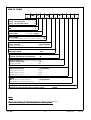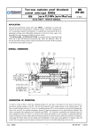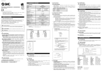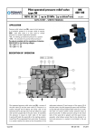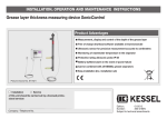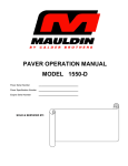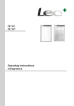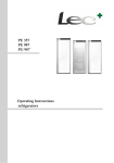
1
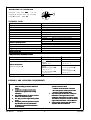
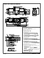
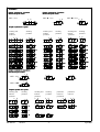
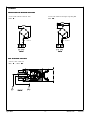
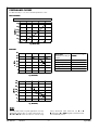
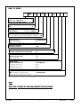
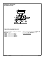
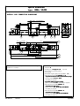
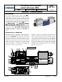
WK
499 775
Intrinsically safe directional
control valve type IWE6
NS6
up to 31,5 MPa up to 20dm3/min
DATA SHEET - OPERAT
RATION MANUA
MANUAL
NUAL
02.2014
APPLICATION
The 4-way directional control valves type IWE6…
electrically operated are intended for change in direction
of fluid flow in a hydraulic system. This valve is mainly
used in hazardous areas especially in underground pit
mines (group I) and in equipment working in vicinity of
flammable substances like gas, vapour, fog (group II). It
is certified with explosion proof attest - ATEX:
ATEX
I M1 Ex ia I Ma;
II 2G Ex ia IIC T6/T5 Gb;
Ma
Gb
GOST - R: PO Ex ia I Ma;
Ma 1Ex ia IIC
IIC T5/T6 Gb. Can work
with outlet explosion proof circuit “ia” or “ib” with
maximum parameters Ui = 15 V;
V li = 1,6 A; Ci = 0;
0 Li = 0.
Temperature classes T5 and T6 are dependent on
ambient temeperature, according to data table on
page 2.
DESCRIPTION OF OPERATION
The directional valve is switched by changing position of
the spool (3) which moving along its axis separates or
connects ports A , B , P , T in the housing (1). The move of
the spool is secured by the putting voltage on coil (2)
through the terminal strip (10) The return of the spool is
realized by the spring (4). A n optional manual override
button (6) permits movement of the spool without
solenoid. The valve is equipped with explosion proof
solenoid type EMSGI – 45. Solenoid is assembled with
sleeve (5) and manual override button (6).
There is a coil (2) on the sleeve (6). Outside of coil
mounted is cable box (7). Inside the cable box (7) are
diodes as well as safety device (9) preventing excessive
current increase. Electrical connection for is realized by
using terminal strip (10) and for type with light signaling
applied diode LED (11). The diode is mounted inside cable
box (7). Power lead must be sealed and immobilized
using gland (12). Sealing rings (14) protect the coil against
external impacts and prevent from turn of coil after
tightening up the nut (13).
4IWE6E12/G12NDL
12
2
7
11
4
14
5
a
b
6
13
A P B
9
T
3
1
10
8
Type IWE6
-1-
WK 499 775
02.2014
DESCRIPTION OF OPERATION
Directional valve type IWE6…
IWE6 … can be
equipped by throttle insert (15) mounting
in port P - version …IWE6…B
B ….
15
P
TECHNICAL DATA
Hydraulic fluid
Required
Required filtra tio
tion
Recommended filtration
Nominal fluid viscosity
Viscosity range
Fluid temperature range
Optimum fluid temperature range
Relative humidity of air
Protective coating
Maximum
Maxim um operating pressure
Maximum
Maxim um flo
fl ow
Weight
Supply vol tage U n
Supply current In
Degree of protec tio
ti on
mineral oil
up to16
to 16 µm
up to10 µm
37 mm 2/s at temperature 55 oC
2,8 up to 328 mm 2/s
-20 up to 60 o C
o
40 up to 55 C
to 95 %
housing
epoxy chemically resistant enamel
hot galvanizing
solenoid
port P , A, B - 31,5 MPa
port T - 21 MPa
20 dm 3 /min
1,6 kg
12 V DC
110 mA
IP 6 5
COMPLIA
PLIAN
IANCE WITH STANDA
ANDAR
DARD SY
S YS T E M
Standard system
Certifica
Certi ficate
fica te of
o f examinati on type
1456
145 6 KO MAG
MAG 06AT EX201X
201 X
- 20 do 40 C
II 2G
2 G Ex ia I IC T6 /T 5 Gb
for class temperature T6
o
- 20 do 40 C
for class temperature T5
o
- 20 do 60 C
1Ex ia I IC T5/T 6 Gb
for class temperature T6
o
- 20 do 40 C
for class temperature T5
o
- 20 do 60 C
o
Quality
Quali ty assurance certi ficate
fica te
RU CC-PL.ГБ08.B.0025
PL. 08.B.00251
08.B.00251
PO Ex ia I Ma
o
- 20 do 40 C
I M 1 Ex ia I M a
Intrinsic
tri nsic safe ty feat ure
Ambient temperature Ta
G O ST - R
ATE
ATEX (94/9/WE)
1026
102 6 FTZ
FT ZU No
N o. FTZ
FT ZU 05 AT EX Q 01 3
ASSEMBLY AND OPERATION REQUIREMENTS
1.
2.
3.
4.
5.
WK 499 775
Electric connection of the valve must be
made according to electric scheme on
page 5.
5.
Conductors of valve must be meet
requirements applied in the mining
machinery.
Only skilled workers can direct connect
valve to an
an electrical system.
The plug must be supported by retains
screw.
During the period of operation must be
kept the fluid viscosity and filtration
according to requirements defined in
Service Manual
02.2014
6.
In order to ensure the failure free and safe
operation must be check:
• condition
condition of the electrical connection
• the verity proper working of the valve
• cleanness of the hydraulic fluid
7. Any valve repair in the mine condition is
forbidden. A damaged valve must be
supplied to the producer in order to repair.
The address of service is shown on the last
page of this Data sheet – Service Manual
8. A person that operates the valve has to
acquaint with Service Manual.
-2-
Type IWE6
OVERALL AND CONNECTION DIMENSIONS
OO
61,5
23
42
b
a
80
2
9,4 - 4 depth holes
5,3 - 4 holes
3
1
2
S6
45
4
8
164
31
32,5
T
A
B
0,75
P
40,5
73
5
81,5
17
7
164
236
1 - Solenoid a
2 - Solenoid b
3 - Sealing ring - o - ring 9,2 x 1,8 - 4 pcs/kit
4 - Manual override
5 - Diode LED - light signaling
(only version IWE6…DLL…)
6 - Valve dimension:
3 - position directional valve with return springs
spri ngs
(solenoids a and b, spool symbols: E , H , J, L, M, U
according to page 4)
2 - position directional valve without return springs
(solenoids a and b spool symbols: A , C, D
according to page 4)
7 - Valve dimension:
2 - position directional
directional valve with return spring
(solenoid a, spool symbols: A, C, D , EA , HA,
LA,MA
HA JA ,LA
LA MA,UA
MA UA
according to page 4)
8 - Valve dimension:
2 - position directional valve with return spring
(solenoid b, spool symbols: B , Y, EB,
EB HB,
HB JB,
JB LB,
LB MB,UB
MB UB
according to page 4)
9 - Porting pattern for directional spool valve
configuration of connection holes in accordance with
the following standards:
• CETOP RP 121H - identified by CETOP 4.2-4-03
(nominal size CETOP 03)
03
• ISO 4401
- identified by ISO 4401-03-02-0-94
mounting bolts M5 x 50 - 10.9 in accordance with
PN - EN ISO 4762 - 4 pcs/kit,
tightening torque Md = 9 Nm
10 - Subplate surface required
O
M5 gł 10 - 4 holes
7,6 (max) - 4 holes (P,T,A,B)
9
T
B
26,55
31,75
32,5
A
P
10,3
19
27,8
40,5
min 73
r
0,75
5,95
16,25
min 45
6
min 17
0,01/100 mm
0,63
10
Type IWE6
-3-
WK 499 775
02.2014
SCHEMES
Grap
Graph
aphic sy
s ymbo
mbols for 2-po
2-p o sit
sition
directtional spo
direc
spoo l valves
Grap
Graph
aphic sy
s ymbo
mbols for 3-po
3-p osit
si tion
directtional spo
direc
spoo l valves
IWE6...1X/...
IWE6..A...1X/...
IWE6...B...1X/...
A
A B
0 b
a
a
P
a
a
b
B
A
0
0 b
T
P
T
B
P
b
T
Grap
Graph
aphic sy
s ymbo
mbols for spo
spo ols
working and
indirect
positions
A
a
B
0
a
b
T
P
B
A
0
P
B
A
b
a
A
0
T
a
T
P
working and
indirect
positions
A B
working
positions
working and
indirect
positions
working
positions
B
P
0
P
T
P
T
B
A
b
0
0
working
positions
b
T
E
EA
EB
H
HA
HB
J
JA
JB
L
LA
LB
M
MA
MB
U
UA
UB
Grap
Graph
aphic sy
s ymbo
mbols for 2-po
2-p osit
si tion
directtional spo
direc
spool valves
A B
...IWE6...1X/...
a
a
...IWE6..1X/O...
a
A
b
a
P
T
B
P
A
B
a b
B
A
b
a
b
a b
T
T
P
b
T
P
Grap
Gr aph
aphic sy
symbo
mbols for spo
sp ools
working and
indirect
positions
working
positions
A B
A B
a
b
P
a
T
working and
indirect
positions
a
b
P
B
A
P
T
B
A
a
b
T
położenia
robocze i
pośrednie
A B
working
positions
P
a
b
B
A
T
B
A
a
b
P
T
położenia
robocze
b
P
T
BX
C
D
WK 499 775
02.2014
Y
-4-
Type IWE6
SCHEMES
Electrical scheme of directional control valve
version with cable box without LED
IWE6…D
D ...
version with cable box and light signaling LED
IWE6…DL
DL…
DL
B1 - 0,25 A
+
B1 - 0,25 A
-
+
(-) (+)
12 V D C
-
(-) (+)
12 V D C
View of electrical
electrical connections
versions with cable box
IWE6…D
D …; IWE6…DL
DL...
DL
+
(-)
Type IWE6
12V DC
DC
(+)
-5-
WK 499 775
02.2014
PERFOMANCE CURVES
For fluid viscosity v = 41 mm2/s and temperature t = 50ºC
Flow resistance
flow direction: P → A; P → B; A → B; A → T
0,6
0,6
∆p [MPa]
0,5
0,5
0,4
0,4
0,3
0,3
0,2
0,2
0,1
0,1
0
5
10
15
Q [dm 3/ min
min]
20
25
Flow limits
35
30
1
p [MPa]
25
Spo
Spool type
schemes according to
page 4
3
E, A, B
A/ O
H, M, C/
C /O, D/
D /O
C, D, J, Y
20
2
15
10
L, U
5
0
5
10
15
3
Q [dm /mi
/ min
min]
20
25
20
25
Perform
Perf orma
orm ance di
d iagram
agr am
number
1
2
3
4
5
35
30
p [MPa ]
25
5
20
15
10
4
5
0
5
10
15
3
Q [dm /min
min]
NOTES:
The flow limits refer to typical application of 4-way
directional control valve i.e. with using 2 lines e.q.
P to A and B to T at the same time. In case of using
WK 499 775
02.2014
4-way directional valve with line e.q. P to A
(B
B plugged) or A to T (B
B plugged) actual flow limits
are considerably lower.
-6-
Type IWE6
HOW TO ORDER
IWE
Number of service ports
3-way - for spools A, B
4-way - for the other spools
=3
=4
Nominal size (NS)
NS6
=6
Spool type
spool symbol
6
12
N
- according to page 4
= 1X
(10-19) - installation and connection dimensions unchanged = 12
Series number
Spool centering/positioning
spring centering
without reverse spring
= no designation
=O
Voltage for solenoids
DC voltage 12V DC
= G12
Manual override
solenoids with manual override button
=N
Electrical connections (schemes according to page 5)
cable box without LED
=D
cable box with LED
= DL
Throttle insert
without throttle insert
throttle insert Ø 0.8 mm
throttle insert Ø 1.0 mm
throttle insert Ø 1.2 mm
= no designation
= B 08
= B 10
= B 12
Sealing
NBR (for fluids on mineral oil base)
FKM (for fluids on phosphate ester base)
= no designation
=V
NOTES:
Orders coded in the way showed above should be forwarded to the manufacturer.
Shorter terms of deli
del ivery f or valves with
ith par
p arameters
arameters in bo
b old are po
p ossib
ssible.
ible.
Coding example: 4IWE6 E 12/G12 N D
Type IWE6
-7-
WK 499 775
02.2014
EXAMPLE OF APPLICATION
IN HYDRAULIC SYSTEM
A
B
4IW
4I WE6 J...
P
T
M
SUBPLATES AND MOUNTING BOLTS
Subplates must be ordered according to the data sheet
WK 496 480. Subplates:
G 34
3 41/01 - threaded connection G 1/
1/4
G 34
3 /8
3 42/01 - threaded connection G 3/
G 34
3 41/02 - threaded connection M14 x1,5
1, 5
G 34
3 42/02 - threaded connection M16 x1,5
1,5
WK 499 775
02.2014
Subplates and bolts fixing directional valve M5 x 50 - 10,9
0,9
in accordance with PN - EN ISO 4762 - 4 pcs/kit
must be ordered separately.
-8-
Type IWE6
Special execution
type ...IWE6...SO495
APPLICATION, DESCRIPTION OF OPERATION,
ASSEMBLY AND OPERATION REQUIREMENTS,
PERFORMANCE CURVES, SCHEMES,
CONNECTION DIMENSIONS, SUBPLATES,
MOUNTING BOLTS,
16
4
as in basic execution of directional control valve
according to pages
pages 1 - 6
button of manual control
in initial position (unlocked)
DESCRIPTION OF OPERATION
Directional control valves type …IWE6…SO495 are
equipped with set of latch spring mounted on
solenoids. Latch spring (16) centrally mounted
forces valve presetting without necessity of manual
pressing on button (4). The button is unlocked after
latch spring release (16) and return the set to initial
position.
NO T E S :
button of manual control locked
Before st artart -up the
t he po
p ositi
ition of latc
l atch
atch spring
spri ngs
ngs of man
ma nual
con
co ntrol
tro l to
t o be chec
c heck
hec ked.
TECHNICAL DATA
Hydraulic fluid
Required
Required filtra tio
ti on
Recommended filtration
Nominal fluid viscosity
Viscosity range
Fluid temperature range
Optimum fluid temperature range
Relative humidity of air
Protective coating
Maximum
Maxim um operating pressure
Maximum
Maxim um flo
flow
Weight
Supply vol tage U n
Supply current In
Degree of protec tio
ti on
mineral oil
up to16
to 16 µm
up to10 µm
o
37 mm 2/s at temperature 55 C
2,8 up to 328 mm 2/s
-20 up to 60 o C
o
40 up to 55 C
to 95 %
housing
epoxy chemically resistant enamel
hot galvanizing
solenoid
port P , A, B - 31,5 MPa
port T - 10 MPa
20 dm 3 /min
1,6 kg
12 V DC
110 mA
IP 65
65
COMPLIA
PL IAN
IANCE WITH STANDA
ANDAR
DARD SY
S Y ST E M
Standard system
Certifica
Certi ficate
fica te of
o f examinati on type
1456
145 6 KOMA
KO MAG
MAG 06ATE
06AT EX201X
201 X
- 20 do 40 C
II 2G
2 G Ex ia I IC T6 /T 5 Gb
for class temperature T6
o
- 20 do 40 C
for class temperature T5
o
- 20 do 60 C
1Ex ia I IC T5/T 6 Gb
for class temperature T6
o
- 20 do 40 C
for class temperature T5
o
- 20 do 60 C
o
Quality
Quali ty assurance certi ficate
fica te
Type IWE6
RU CC-PL.ГБ08.B.0025
PL. 08.B.00251
08.B.00251
PO Ex ia I Ma
o
- 20 do 40 C
I M 1 Ex ia I M a
Intrinsic
tri nsic safe ty feat ure
Ambient temperature Ta
GOST - R
ATE
ATEX (94/9/WE)
1026
No
o. FTZ
FT ZU 05 AT EX Q 01 3
102 6 FTZ
FT ZU N
-9-
WK 499 775
02.2014
Special execution
type ...IWE6...SO495
OVERALL AND CONNECTION DIMENSIONS
OO
42
61,5
b
23
a
80
9,4 - 4 depth holes
5,3 - 4 holes
3
1
S6
2
8 bolts
5
45
4
9
197
31
32,5
T
A
B
0,75
P
115
40,5
73
6
17
8
197
7
303
View of connection and required conditions of connecting
surface acc. to page 3.
WK 499 775
02.2014
1 - Solenoid a
2 - Solenoid b
3 - Sealing ring - o - ring 9,2 x 1,8 - 4 pcs/kit
4 - Press button of manual control
5 - Lock spring
6 - Diode LED - light signal (only type IWE6…DLL…)
7 - Valve dimension with 2 solenoids - a, b:
b
•3
3 -position
po sition directional valve centered with springs
(spool symbols: E, H , J, L, M, U
according to page 4)
•2
2 - position without reverse springs
(spool symbols: A, C , D - according to page 4)
8 - Valve dimension with 1 solenoid - a
•2
2 -position
pos ition set with spring
(spool symbols: A , C , D, EA,
EA HA , JA,LA
JA LA,MA
LA MA,UA
MA UA
according to page 4)
9 - Valve dimension with 1 solenoid - b
•2
2 -position set with spring
(spool symbols: B , Y, EB,
EB HB,
HB JB,
JB LB,
LB MB,UB
MB UB
according to page 4)
- 10 -
Type IWE6
HOW TO ORDER
IWE
Number of service ports
3-way - for spo ols A, B
4-way - for the other spools
=3
=4
Nominal size (NS)
NS6
=6
Spool type
spool symbol
6
12
N
- according to page 4
= 1X
Series number
(10-19) - installation and connection dimensions unchanged = 12
Spool centering/positio ning
spring centering
without reverse spring
= no designation
=O
Voltage for solenoids
DC voltage 12V DC
= G12
Manual override
solenoids with manual override button
=N
Electrical connections (schemes according to page 5)
cable bo x without LED
=D
cable box with LED
= DL
Throttle insert
without throttle insert
throttle insert Ø 0.8 mm
throttle insert Ø 1.0 mm
throttle insert Ø 1.2 mm
= no designation
= B 08
= B 10
= B 12
Sealing
NBR (for fluids on mineral oil base)
FKM (for fluids on phosphate ester base)
= no designation
=V
Special type
solenoids with latch spring of button manual control
= SO495
NOTES:
Orders coded in the way showed above should be forwarded to the manufacturer.
Shorter terms of delivery for valves with parameters in bold are possible.
Coding example: 4 IWE6 E12/G12 N D SO495
Type IWE6
- 11 -
WK 499 775
02.2014
PONAR Wadowice S.A.
ul. Wojska Polskiego 29
34-100 Wadowice
tel. +48 33 488 29 00
fax.+48 33 488 21 03
www.ponar-wadowice.pl
WK 499 775
02.2014
- 12 -
Type IWE6