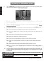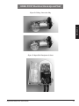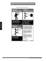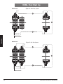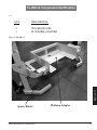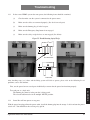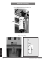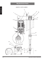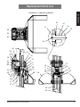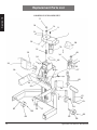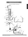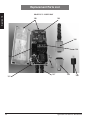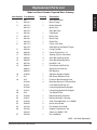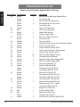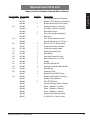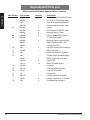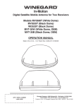
1
OPERATION AND SERVICE INSTRUCTIONS Heavy-Duty Mobile Above Ground Lifts HDML-6 HDML-8 HDML-9 Forklift Adapters FL-3 FL-3-4 FL-OM-12 IMPORTANT SAFETY INSTRUCTIONS READ ALL INSTRUCTIONS SAVE THESE INSTRUCTIONS Automotive Resources, Inc. 12775 Randolph Rige Lane ● Manassas, VA 20109 (800) 562-3250 ToIl Free (703) 359-6265 Local (703) 359-6405 Fax www.ari-hetra.com Web Site [email protected] E-Mail February 2007 Edition Introduction This manual provides operation and service instructions and parts breakdown for the ARI-HETRA Heavy-Duty Mobile Lift (HDML) Systems: Models HDML-6AE Series, 8AE Series, 9AE Series and all FL Series. Read this manual thoroughly before installing, operating, servicing or maintaining the lift and/or forklift adapters and pay particular attention to the WARNINGS and CAUTIONS. The ARI-HETRA systems must be used in accordance with the manual; any misuse will void warranty. ARI-HETRA has many years of experience in mobile lift manufacturing. This, coupled with our continual working relationship with fleet owners, managers and mechanics, contributes to bringing you the most advanced lifting technology today. ARI-HETRA’s Priorities Are: SAFETY SERVICE SALES Any specific recommendations to enhance this publication are invited and would be appreciated. The HDML is approved for indoor installation and use only. The HDML is not intended for outdoor use. Operation and Service Instructions IMPORTANT SAFETY INSTRUCTIONS When using your garage equipment basic safety precautions should always be followed, including the following: 1. Read and understand all instructions for the lift and all optional accessories. 2. Inspect the HDML Lifting System daily before use. 3. Care must be taken as burns can occur from touching hot parts. 4. Do not operate equipment with a damaged cord or if the equipment has been dropped or damaged – until it has been examined by a qualified service person. 5. Do not let a cord hang over the edge of the table, bench or counter, or come in contact with hot manifolds or moving fan blades. 6. If an extension cord is necessary, a cord with a current rating equal to or more than that of the equipment should be used. Cords rated for less current than the equipment may overheat. Care should be taken to arrange the cord so that it will not be tripped over or pulled. 7. Always unplug equipment from electrical outlet when not in use. Never use the cord to pull the plug from the outlet. Grasp plug and pull to disconnect. 8. Let equipment cool completely before putting away. Loop cord loosely around equipment when storing. 9. To reduce the risk of fire, do not operate equipment in the vicinity of open containers of flammable liquids (gasoline). 10. Adequate ventilation should be provided when working on operating internal combustion engines. 11. Keep hair, loose clothing, fingers and all parts of body away from moving parts. 12. To reduce the risk of electric shock, do not use on wet surfaces or expose to rain. 13. Use only as described in this manual. Use only ARI-HETRA optional accessories and attachments. 14. ALWAYS WEAR SAFETY GLASSES. Everyday eyeglasses only have impact resistant lenses, they are not safety glasses. 15. Only allow qualified personnel to operate, maintain, service or repair the lift. 16. Never modify the lift or add/use unapproved adapters or optional equipment to/with the lift. 17. Never overload the lift. The rated load is printed on the lift name plate. 18. Never allow anyone to climb on or ride in the vehicle when raised or lowering. 19. Know and follow all local, national and international health and safety regulations. SAVE THESE INSTRUCTIONS Operation and Service Instructions Letter From The President SUBJECT: FROM: TO: Safety Advisory Robert S. Penenburgh President ALL USERS OF THE ARI-HETRA MOBILE LIFTING SYSTEM As President of AUTOMOTIVE RESOURCES, INC. (ARI), I am writing to you, a valued customer, to remind you that we believe the ARI-HETRA mobile lifting systems are the finest on the market. However, like any other industrial tool, our systems perform most effectively and safely when used in the manner and for the purpose they are designed. Safety is a major concern at ARI! ARI-HETRA systems are clearly marked with several warning labels. The Operation and Service Instructions are provided with each system, which describes explicitly the way in which the equipment should be used. The ARI-HETRA hoist is a wheel-engagement system. If a user attempts to use the lifts in any other manner (for example, by lifting the bumpers of a vehicle rather than by the tires), the lift will not perform properly. Improper use could cause injury to the operator, damage to the vehicle or to the lifting system itself. Please stress to your personnel/users the need to follow the instructions on the warning labels and those contained in the Operation and Service Instructions. ARI-HETRA is designed only for use as a wheel engagement system and for use with ARI-HETRA optional equipment and accessories. If wheel-free access is required, please use our adjustable support stands, chassis cross beam and/or FL forklift adapters, in order to engage the vehicle frame members correctly. Should you have any questions, do not hesitate to contact your local ARI-HETRA Representative or if your prefer, you may call me directly. Sincerely yours, Robert S. Penenburgh President Operation and Service Instructions Operation and Service Instructions Table of Contents Sections Introduction.................................................................................................................................................................... 1 Letter from the President............................................................................................................................................... 3 Table of Contents .......................................................................................................................................................... 5 Section 1 General Specifications............................................................................................................................... 7 Section 2 Owner/Employer Responsibility............................................................................................................... 9 Section 2 Unpacking the ARI-HETRA System....................................................................................................... 10 Section 3 Moving Posts............................................................................................................................................. 11 Section 4 Electrical Hook Up and Test..................................................................................................................... 13 Section 5 Operation / Orientation.............................................................................................................................. 17 Section 6 Operational Precautions............................................................................................................................ 21 Section 7 Start Up...................................................................................................................................................... 27 Section 8 Optional Equipment.................................................................................................................................. 29 Section 9 Support Stands........................................................................................................................................... 31 Section 10 Forklift Adapters – FL-3 & FL-3-4........................................................................................................... 33 Section 11 Lifting Platform – FL-OM-12................................................................................................................... 40 Section 12 Troubleshooting......................................................................................................................................... 45 Section 13 Manual Lowering of the ARI-HETRA System....................................................................................... 49 Section 14 Wiring Schematics..................................................................................................................................... 51 Section 15 Replacement Parts List.............................................................................................................................. 55 Section 16 General Lockout/Tagout Procedure........................................................................................................... 67 Section 16 Maintenance Service................................................................................................................................. 69 Section 17 Extended Warranty and Preventative Maintenance Programs.................................................................. 75 Quarterly Service Inspection Check List(s).................................................................................................................. 71 Figures Figure A Figure B Figure C Figure D Figure E Figure F Figure G Figure H Figure I Figure J Figure K Figure L Figure M Figure N Figure O Figure P Figure Q Figure R Figure S Figure T Figure U Figure V Figure W Figure X Figure Y Technical Data/Dimensions of a Standard Carriage................................................................................. Shipping Pallet ......................................................................................................................................... Hydraulic Jack Operation . ....................................................................................................................... Voltage Conversion Plug........................................................................................................................... Input Pilot Transformer Selector............................................................................................................... Post & Cable Distribution......................................................................................................................... Control Panel . .......................................................................................................................................... Manufacturer's Identification Plate........................................................................................................... Warning Operation Instruction Label........................................................................................................ Caution Label............................................................................................................................................ Safety Instruction Label............................................................................................................................ Warning Label........................................................................................................................................... Safety Tips . .............................................................................................................................................. Automotive Lift Institute Label................................................................................................................. Four Post System....................................................................................................................................... Six Post System......................................................................................................................................... Support Stands........................................................................................................................................... Reduction Sleeves...................................................................................................................................... FL-3 Components...................................................................................................................................... FL-3-4 Components ................................................................................................................................. FL-OM-12 ................................................................................................................................................ Technical Data/Dimensions of a FL-OM-12 ........................................................................................... Troubleshooting Safety Wedge ................................................................................................................ Manual Brake Release Tool & Access Port.............................................................................................. Safety Wedge............................................................................................................................................. Operation and Service Instructions 7 10 11 15 15 18 18 21 22 23 24 25 26 26 28 28 29 29 34 35 41 42 45 50 50 Table of Contents Figures Figure Z Figure AA Figure BB Figure CC Figure DD Figure EE Figure FF Power Box Electrical Schematic............................................................................................................... Post Electrical Schematic.......................................................................................................................... Electrical Components.............................................................................................................................. Switch Set to Off ...................................................................................................................................... Lockout Tag on Power Box . .................................................................................................................... Lifting Nut Lubrication............................................................................................................................. Hydraulic Jack........................................................................................................................................... 51 52 53 68 68 70 70 Drawings / Photos Drawing I Drawing II Drawing III Drawing IV Photo V Drive Assembly ...................................................................................................................................... 56 Carriage Assembly ......................................................................................................................... ........ 57 Exploded View ....................................................................................................................................... 58 Electrical Components ........................................................................................................................... 59 Power Box .............................................................................................................................................. 60 Operation and Service Instructions 1.1 Section 1 General Specifications ARI-HETRA manufactures various models of heavy-duty mobile lifts. Model Specifications Number Capacity Model of Per Specification Columns Column HDML 6-4AE 412,000 lbs. HDML 6-6AE 612,000 lbs. HDML 8-4AE 415,000 lbs. HDML 8-6AE 615,000 lbs. HDML 8-4-WAE 415,000 lbs. HDML 9-4AE 416,000 lbs. HDML 9-6AE 616,000 lbs. HDML 9-4-WAE 416,000 lbs. CAUTION NOTE: Total Capacity 48,000 lbs. 72,000 lbs. 60,000 lbs. 90,000 lbs. 60,000 lbs. 64,000 lbs. 96,000 lbs. 64,000 lbs. Power System Requirements Amperage (3 Phase) 30/15208-230/460-480 50/20230/460-480 30/15208-230/460-480 50/20230 /460-480 30/15208-230/460-480 30/15208-230/460-480 50/20230 /460-480 30/15208-230/460-480 Confirm power supply and system wiring MATCH before applying power. All systems come standard with 208/230 wiring (See 460 Volt Conversion Procedures, Page 14). Figure A: Technical Data/Dimensions of a Standard Carriage Operation and Service Instructions Section 1 General Specifications 1.2 Additional Technical Data Lifting Height (Inches) 68 Length (Inches) 41 Width (Inches) 45 Maximum Height (Inches) 92 Lifting Time To Maximum Height (Seconds): HDML-6AE 95 HDML-8AE 105 HDML-9AE 115 Control Voltage110 Volts Tire Sizes, Accepted (Standard Carriage)12R - 24.00 to 10.00 - 19.00 Tire Sizes, Airport Equipment (Tug)14.00 R 24 Tire Sizes, With Reduction Sleeves (On Standard Carriage) (EP-2 or EP-2-HD) P135 R 13-8.25 x 20 Weight of Each Post (Standard Carriage) Approximately 975 lbs. Foundation/Floor Requirements 3000 psi concrete min 6" thick (Specifications subject to change without notice.) 1.3 Warranty One year warranty on parts and labor. Operation and Service Instructions 2.1 Lift Operator Qualifications and Training The owner/employer shall ensure that all lift operators have the appropriate qualifications and that they are trained in the safe operation of the lift by making use of the following materials: ARI-HETRA supplied Operation and Service Instructions; ALI/SM 05-1, ALI Lifting It Right safety manual; ALI/ST 90 Safety Tips (Page 26) ANSI/ALI ALOIM – 2000, American National Standard for Automotive Lifts – Safety Requirements for Operation, Inspection and Maintenance; ALI/WL series, ALI Uniform Warning Label Decals/ Placards; and if required, ALI/LP-Guide, Vehicle Lifting Points/Quick Reference Guide for Frame Engaging Lifts. Operator training shall be appropriately documented in accordance with ANSI/ALI ALOIM-2000. 2.2 Display of Information Materials The owner/employer shall display the following information materials in a prominent location in the lift area: ARI-HETRA Operation and Service Instructions; ALI/SM 05-1, ALI Lifting It Right safety manual; ALI/ST 90 Safety Tips card; ANSI/ALI ALOIM-2000, American National Standard for Automotive Lifts – Safety Requirements for Operation, Inspection and Maintenance; ALI/WL series, ALI Uniform Warning Label Decals/ Placards; and if required, ALI/LP-Guide, Vehicle Lifting Points/Quick Reference Guide for Frame Engaging Lifts and ANSI/SAE J2184-May2000, Vehicle Lift Points for Service Garage Lifting. 2.3 Periodic Inspection The owner/employer shall establish a periodic inspection procedure in accordance with ARI-HETRA’s recommendations (Page 71 & 73) or ANSI/ALI ALOIM-2000. The owner/employer shall ensure that all lift inspectors have the appropriate qualifications and that they are trained in the inspection of the lift. Periodic inspections shall be appropriately documented in accordance with ARI-HETRA’s recommendations or ANSI/ALI ALOIM-2000. 2.4 2.5 2.6 Preventative Maintenance The owner/employer shall establish a preventative maintenance procedure in accordance with ARI-HETRA's recommendations (Page 71 & 73) or ANSI/ALI ALOIM-2000. The owner/employer shall ensure that all preventative maintenance personnel have the appropriate qualifications and that they are trained in the preventative maintenance of the lift. Preventative maintenance shall be appropriately documented in accordance with ARI-HETRA’s recommendations or ANSI/ALI ALOIM-2000. Repair Maintenance The owner/employer shall perform repair and maintenance procedures whenever considered necessary by lift operator, lift inspector or preventative maintenance personnel in accordance with ARI-HETRA’s recommendations (Page 71 & 73) or ANSI/ALI ALOIM-2000. The owner/employer shall ensure that all technicians have the appropriate qualifications and that they are trained in the repair and maintenance of the lift. Repair and maintenance shall be appropriately documented in accordance with ARI-HETRA’s recommendations or ANSI/ALI ALOIM-2000. The owner/employer shall provide appropriate Lockout/Tagout means for all energy sources in accordance with ANSI Z 244. 1-2003 (R1993), Safety Requirements for the Lockout/Tagout of Energy Sources (Page 67). This shall be done before any repair work is performed. ARI-HETRA recommends its quarterly service plan (Page 75). Modifications The owner shall not modify or reconstruct any lift. Owner modifications will void lift warranty and release ARI-HETRA of all liability. Operation and Service Instructions Section 2 Owner/Employer Responsibility Unpacking the ARI-HETRA System Two (2) ARI-HETRA posts are shipped on one (1) pallet. Each post is marked with a serial number and the power box is in the cardboard box underneath the front carriage. Section 2 2.7 Figure B: Shipping Pallet For additional installation safety information see ANSI/ALI ALIS, Safety Requirements for Installation and Service of Automotive Lifts. 2.8 Each post is shipped in an upright position. Care must be used when unpacking to prevent damage. The lift is bolted at the base of the unit to the pallet. 2.9 The following eight (8) steps are recommended to facilitate proper unpacking of the ARI-HETRA system: Step 1: Check all the posts for any transport damage and report it to the freight forwarder. Step 2: Remove the shipping bracket on top by unscrewing the bolts. (Screw the supplied rings back in place.) Step 3: Remove the two (2) hydraulic jack/steering assemblies from the pallet. Step 4: Remove the cardboard box containing the power box. Step 5: Loosen the two (2) bolts which secure the post to the pallet. Cut the steel banding. Step 6: Lift the post (weight approximately 1,000 lbs) by the lifting ring with a forklift or hoist from the pallet. Step 7: Mount hydraulic jack/steering assembly with four (4) bolts to the base of the post. Step 8: To set up, please read the Operation and Service Instructions and warning labels attached to each post. 2.10 10 The steering wheel has a hydraulic jack installed for raising the unit. To raise the unit, close the hydraulic valve by turning it clockwise. Operate the hydraulic jack handle and the post will raise. Raise the post just enough to clear the floor. CAUTION If post is raised too high, the steering tube will come out of the hydraulic jack holder. WARNING To lift the post, use the lifting ring located at the top of the post. DO NOT lift the post by any other point, thereby avoiding serious damage to the post. Operation and Service Instructions HDML Operation - Moving Posts To enhance mobility, each ARI-HETRA post has self-contained wheels and a hydraulic jack/steering assembly. 3.2 Before attempting to move post be sure: ● Power has been disconnected; ● All cables are disconnected; ● Post forks are in the “down” position and NOT under load. 3.3 To raise post, close the valve on the hydraulic jack on the steering assembly. Operate the hydraulic jack handle in a pumping action and the unit will raise to allow movement. Once positioned under vehicle’s tires the hydraulic jack valve must be opened, which allows the lift to be completely lowered thereby avoiding damage to the jack system during lift use. CAUTION Section 3 3.1 Raise unit just enough to clear the floor. If post is raised too high, the steering tube will come out of its holder. Figure C: Hydraulic Jack Operation Operation and Service Instructions 11 Section 3 12 Operation and Service Instructions HDML POST Electrical Hook-Up and Test 4.1 ARI-HETRA power box, power requirement and set up are: 208/230 (200 - 250) Volts - 3 Phase - 60 Hertz - 30 Amps. If six posts are used, 50 Amps are required. 4.2 The ARI-HETRA power box is supplied with 50' of cable. Note: Power box may be located on any one (1) post. It is recommended that a disconnect plug be installed on the end of the cable, allowing it to be plugged into receptacles located throughout shop. Connect the external power as shown below. Connect External Power WARNING White Voltage: Red 208-230 or 460-480 Black 3 Phase, 4 Wire Green Ground The system must be grounded at all times. Use of non-grounded outlet is a safety hazard. 4.3 The ARI-HETRA power box contains a phase polarity detector. This sensor monitors incoming power for phase sequence, missing phase and low voltage. The detector will select the proper phase sequence to allow the ARI-HETRA system to operate in the proper direction regardless of incoming phase sequence. 4.4 Electrically Interconnecting ARI-HETRA Posts: Remove connector (dummy plug) from the power box located on the post closest to the power source. Connect female connector from power box to the male connector (right) on the first post. Connect second, third and fourth posts together with interconnect cables. On the last post, connect the dummy plug that was removed from the power box. All ARI-HETRA posts are now electrically interconnected. Operation and Service Instructions 13 Section 4 460/480 (440 - 500) Volts - 3 Phase - 60 Hertz - 15 Amps. If six posts are used, 20 Amps are required. If eight posts are used, 30 Amps are required. HDML POST Electrical Hook-Up and Test 4.5 Conversion Instructions 208-230 Volts to 460 Volts: If your system is not set up for the correct voltage, below are instructions on how to make the changes. Otherwise, please go to the next section of this manual. Call your Regional Manager or ARI-HETRA for the voltage conversion plugs if needed. WARNING This conversion must be performed on each post. Section 4 Printed Circuit Board (a) The printed circuit board can be accessed by removing the three (3) 10mm nuts from the black disc on the bottom of the aluminum control housing (Item 73, Page 59). (b) Slowly lower the disc to remove the printed circuit board. Unplug the orange connector on the right and release the board until the orange, eleven-pin voltage conversion plug is visible on the upper left side of the board. (c) Remove the eleven-pin voltage conversion plug. The new plug has only six (6) pins. It must be installed in the top of the connector. Make sure that the numbers on the plug match those printed on the board (See Figure D, Page 15). (d) Make sure all other connectors on the board are still plugged in. The motor connectors on the backside of the board must not be interchanged. If unplugged, make sure that the numbers on the board match those on the plugs. (e) Slide board back into the housing. If slid all the way out, board must be in the large slots. Make sure not to pinch the wires between the housing and the disc. (f) Reinstall wire ties on all connectors removed from printed circuit board. Power Box Only 14 (a) Open power box by unscrewing the four (4) screws. (b) On the top of the box is a printed circuit board. On the left of this board are two (2) fuses and a terminal strip. The red wire must be relocated on the terminal strip from #1 (208/220 position) to #3 (408/480 position). To release the wire, insert a small screwdriver in the slot above the wire (See Figure E, Page 15). (c) The two (2) fuses on the left side of the board named “input pilot fuse” must be changed from 6.3 Amps to 4 Amps. Operation and Service Instructions HDML POST Electrical Hook-Up and Test Section 4 Figure D: VoItage Conversion Plug Figure E: Input Pilot Transformer Selector Operation and Service Instructions 15 Section 4 16 Operation and Service Instructions 5.1 The ARI-HETRA system will provide reliable, efficient service and increase plant productivity. It is essential that all operators of the ARI-HETRA system be properly trained. Once all lift posts have been tested and are working satisfactorily, you now can proceed with lifting a vehicle. 5.2 There are several Warnings and/or Safety Precautions that must be exercised at all times: (a) The ARI-HETRA system should be used on a solid 3000 psi concrete floor minimum 6" thick. The floor where the vehicle is to be lifted should be reasonably flat and capable of supporting the vehicle and the lift. (b) Raise each lift post with its hydraulic jack so the post can be moved under the tires of the vehicle. Position the power box post first (post with electrical power cable) to allow the shortest most convenient distance to the power source (see Figure F, Page 18). (c) Push the lift post forks completely under tire with carriage square to the wheel of vehicle (see Figure F, Page 18). (d) Lower lift to the floor by releasing the hydraulic jack valve. Make sure lifting posts are resting completely on the floor before lifting the vehicle. This maximizes stability of the lift system and precludes damage to the hydraulic jack. (e) Position all other posts under the remaining wheels. Push the lift column forks completely under the tire with carriage square to the wheel of vehicle. (f) Lift by the rear wheels of a tandem axle vehicle (see Figure F, Page 18). The lifting capacity per axle is 24,000 pounds for the HDML-6AE, 30,000 pounds for the HDML-8AE and 32,000 pounds for the HDML-9AE. If the rear axle load is higher than the rated capacity of the ARI-HETRA lift, two (2) additional lift posts should be used on the other axle (Section 7.7 Page 27). This will provide 48,000 pounds lifting capacity at the tandem axle area for the HDML-6AE, 60,000 pounds for the HDML-8AE and 64,000 pounds for the HDML-9AE. WARNING Do not exceed rated capacity of each lift post, as indicated on the identification label. Operation and Service Instructions 17 Section 5 HDML POST Operation/Orientation HDML POST Operation/Orientation 0!'% Figure F: Post & Cable Distribution Section 5 $5--90,5' 0/7%2"/8 0/7%23/52#% 5.3 After all lift posts are in position, connect cables between all lifting posts. Install the dummy plug in the last post. Plug in electrical power cable and turn external power on. Turn power switch (2) on power box to the “on" position (see No. 2, Figure I, Page 22). On each post select the 'MULTI' post mode of operation by pressing the 'MULTI' button on the keypad. The LED above the 'MULTI' button will light. If any of the posts are in 'SINGLE' mode the 'SINGLE' and 'MULTI' LEDs will blink, alternating. If neither of the LEDs are blinking or lighted, check to see that the dummy plug is properly in place or that a red Emergency Stop button has been pushed. Pull or twist to release the red Emergency Stop button. 5.4 SINGLE MULTI The ARI-HETRA system is now ready to lift a vehicle. Figure G: Control Panel 18 Operation and Service Instructions HDML POST Operation/Orientation WARNING Before raising the vehicle: ● Do not lift vehicle in an inclined position, side to side or end to end. ● Do not stand or move under the lift when operating. ● Release brakes of vehicle and put in neutral before operating lift. ● In case of trouble, release the "up/down" push button immediately. ● Do not operate the lift if any safety device is inoperative. ● Do not override or put any safety device out of operation. ● ● ● Do not use the unit for any other purpose than its intended use. The unit is not designed to be used as a bumper lift. Do not lift vehicles weighing more than the rated capacity of the lift. Operation of unit can be stopped at any time by releasing the push button switch or pushing the Emergency Stop Button. ● Before lowering vehicle, be sure all obstructions are removed from the vicinity of the vehicle. ● Do not allow any person to operate the control of the lift when people are underneath the raised vehicle. ● ● ● When performing maintenance work on the unit, always remove vehicle from the unit and be sure power is disconnected from the unit, unless required for checking unit. There are warning and operation decals on the unit. Be sure you read and understand if you operate or maintain the lift. Do not remove decals from the unit. Keep warning/operating plates clean so they can be read easily by all operating and maintenance personnel. Contact ARI-HETRA for free replacements if required. ● Perform scheduled maintenance inspections as required. (Quarterly as a minimum). ● When replacing parts on the unit use only ARI-HETRA parts. ● Observe complete area when lifting or lowering vehicle. Use a second person to observe the area which the operator cannot see. Section 5 ● Order replacement parts from the sales agency from whom the unit was originally purchased, or from ARI-HETRA. Operation and Service Instructions 19 HDML POST Operation/Orientation 5.5 Raising the vehicle: (a) Push the "up" button on the keypad (see No. 4, Figure I, Page 22). All lifting posts will start to lift vehicle. When lift begins to pick-up load, stop operation and check that all forks are fully engaged under tires and each lifting post is clear of vehicle. CAUTION (b) As the vehicle raises, observe that each lifting post is clear of vehicle and will not rub against side of vehicle as it raises. Continue raising vehicle, stopping and checking both sides of vehicle during the raising cycle. The lifting and lowering of vehicle can be done at any lifting post using the “up” or “down” button. Section 5 CAUTION During the raising and lowering of vehicle, observe that the vehicle is staying level. If vehicle is not level, release the switch. To level the vehicle, press the 'SINGLE' button to put the post into 'SINGLE' post mode of operation (see No. 6 Figure I, Page 22). The post is in 'SINGLE' mode and can now be raised or lowered to level the vehicle. Repeat at other posts if necessary. Operate the lifting post which will level the vehicl Once the vehicle is level, return all posts to the 'MULTI' post mode of operation by pressing the 'MULTI' button. (c) Once vehicle is raised, turn power box switch to “off’ position or push-in the Emergency Stop button on any post. This will prevent operation of the lift while someone is under the vehicle. CAUTION 20 Do not operate lift when individuals are under vehicle. Operation and Service Instructions HDML POST Operational Precautions 6.1 6.2 Various warning labels and operating instructions are applied to each post (see Figures I - N, Pages 22 - 26). Labels are normally applied at the factory, howerver if necessary, replacement labels are available from ARI-HETRA corporate office. Each post has an “Identification Plate” containing the manufacturer's item description data (see Figure H, Below). Section 6 Figure H: Manufacturer's Identification Plate Operation and Service Instructions 21 HDML POST Operational Precautions Figure I: Warning Operation Instruction Label 7!2.).' #OPPERMINE$RIVE -ANASSAS6! &!8 "EFOREOPERATINGTHISLIFT Section 6 2EADOWNERSMANUALFORCOMPLETE/PERATIONAND3ERVICE)NSTRUCTIONS $ONOTEXCEEDRATEDCAPACITYOFLIFT -AKESUREFLOORISSTRONGENOUGHTOSUPPOR TLOADOFLIFT )NSTALLFORKSCOMPLETELYUNDERTIRES /PENHYDRAULICVALVEBEFOREOPERATING 2ELEASEBRAKESOFVEHICLEANDPUTINNEUTRALBEFOREOPERATINGLIFT $ONOTSTANDORMOVEUNDERLIFTWHENOPERATING 5SEASECONDPERSONTOOBSERVECOMPLETEAREAWHENLIFTINGORLOWERING )NCASEOFTROUBLEPUSHRED%MERGENCY3TOPBUTTONIMMEDIATELY $ONOTOPERATETHISLIFTIFANYSAFETYDEVICEISINOPERATIVE $ONOTOVERRIDEORPUTANYSAFETYDEVICEOUTOFOPERATION $ONOTATTEMPTREPAIRINGUNTILFIRSTTURNINGPOWEROFF 2EPLACECABLESWHENDAMAGED $ONOTUSELIFTFORANYTHINGOTHERTHANITSINTENDEDUSE ,OWERFORKSANDDISCONNECTALLCABLESBEFOREMOVINGLIFT 0/7%2"/8 $5--90,5' #ABLE(OOK5P !NYPOSTMAYBEUSEDFORTHEPOWERBOX !DUMMYPLUGMUSTBEUSEDONTHELASTPOST !LWAYSCHECKFORPROPERPOWERSOURCE !LWAYSLIFTBYREARMOSTWHEELS #ABLETOPOWERSOURCE -AINPOWERSWITCHONOFF #ABLETOFIRSTPOST 5PBUTTON $OWNBUTTON 3I).',%BUTTON -5,4)BUTTON $IGITALDISPLAYREADOUT %MERGENCY3TOPBUTTON -ANUALLOWERINGACCESS #ABLETONEXTPOST 3YSTEM4ROUBLESHOOTING #HECKPOWERSUPPLYBYINSTALLINGADUMMYPLUGTOPOWERBOX 2ECHECKCABLEHOOKUP -AKESUREADUMMYPLUGISINSTALLEDINTHELASTPOST %MERGENCY3TOPBUTTONSMUSTBEDISENGAGEDONALLPOSTS #ARRIAGEMOVEMENTSENSORMAYRESPOND3WITCHOFFMAINPOWERFOR SECONDSTHENSWITCHONAGAINTORESET 3AFETYWEDGEMAYBEENGAGEDPROCEEDASBEFOREANDLIFTUPUNITBYINCHES BEFORELOWERINGAGAIN )FALLATTEMPTSFAILCHECKMANUALORCALLSERVICEAGENT 086-01AE 22 Operation and Service Instructions HDML POST Operational Precautions Section 6 Figure J: Caution Label Operation and Service Instructions 23 HDML POST Operational Precautions Section 6 Figure K: Safety Instruction Label 24 Operation and Service Instructions HDML POST Operational Precautions Section 6 Figure L: Warning Label Operation and Service Instructions 25 HDML POST Operational Precautions Section 6 Figure M: Safety Tips Figure N: Automotive Lift Institute Label This product was manufactured by a member of the Automotive Lift Institute, Inc., the North American trade association of lift manufacturers dedicated to promoting responsible design, construction, installation, use, and maintenance of automotive vehicle service lifts. 26 Operation and Service Instructions HDML Post Start Up 7.1 On each post control box is an Emergency Stop button (No. 9, Figure I, Page 22). To release button, twist. Make sure these buttons are released at each post. 7.2 On each lift post there is a button on the keypad, which allows selection of multiple 'MULTI' lift post operation or 'SINGLE' lift post operation. Select the multiple position 'MULTI' on each post (No.7, Figure I, Page 22). 7.3 Turn power switch (No.2, Figure I, Page 22) to the “on” position. Make sure external power is present. When power is on, the LEDs and Digital Display Readout will be illuminated. Test every post to ensure it responds to the “up” and “down” buttons (No.4 & No.5, Figure I, Page 22). 7.4 With all lifting carriages completely lowered, select position 'MULTI' with the selector button (No.7, Figure I, Page 22). LEDs above the 'MULTI' will remain on and will not blink. Check lights at each post. Push the "up" button (No.4, Figure I, Page 22) on one of the posts. The carriages of all the lifts will rise together. 7.5 Let carriages rise until all have reached their upper limit. Then lower by using the "down" button (No.5, Figure I, Page 22). Make sure all carriages are completely lowered before turning off the electrical power. 7.6 Disconnect cables before relocating for use in another location andIor storage. 7.7 Section 7 CAUTION (a) Always disconnect the power cable from the outlet before moving the post. (b) Always disconnect connection cables at the left (male) connector keeping the right (female) connector end plugged into each post. (c) Never lay plugs on the ground as they can become damaged. For storage, wrap the cable around the hook on the motor gearbox. (d) Never move the lift posts with the cables connected or with the cables laying on the ground. (e) Never drive over the connection cables. (f) Never operate a welder or cutting torch in the vicinity of the connection cables. To operate as a six-post system - add two (2) posts and two (2) cables as shown. (see Figure O, Page 28) Operation and Service Instructions 27 HDML Post Start Up 0!'% $5--90,5' Figure O: Four Post System 0/7%2"/8 Section 7 0/7%23/52#% $5--90,5' Figure P: Six Post System 0/7%2"/8 0/7%23/52#% 28 Operation and Service Instructions Optional Equipment 8.1 8.2 Support Stands - ARI-HETRA system stands are available with rated capacity of 15,000 pounds each. A description and how to use the stands is in Section 9 herein. Stands are available as follows: AB-6-07 Short Support Stand, capacity: 15,000 pounds, weight: 35 pounds, adjustable from 17.5"28.5" at 1.25" steps AB-6-l2 Medium Support Stand, capacity: 15,000 pounds, weight: 53 pounds, adjustable from 29.5"47.2" at 2.00" steps (See Figure Q, Below) AB-6-20 Tall Support Stand, capacity: 15,000 pounds, weight: 145 pounds, adjustable from 47.2"-78.8" at 2.95" steps SP-75 Screw-Fine Adjustment for AB-6-20 support stands only, adjustable from 2"-4", weight: 15 pounds Reduction Sleeves for lifting small tired vehicles (down to a 9” rim) are available, which fit onto the forks of the carriage. These sleeves make the fork's opening more narrow allowing small tired vehicles to be lifted. The reduction sleeve(s) may be used individually or in pairs (See Figure R, Below). Model EP-2 – Down to 13” rim (5,000 lb. capacity) Model EP-2-HD – Heavy-Duty down to 13” rim (15,000 lb. capacity) Model EP-2-9 – Down to 9” rim (5,000 lb. capacity) Do not attempt to lift small tired vehicles without using the reduction sleeves. Smaller tires could slip through the forks of the lift. Figure Q: Stands Operation and Service Instructions Section 8 WARNING Figure R: Reduction Sleeves 29 Section 8 30 Operation and Service Instructions Support Stands 9.1 For each ARI-HETRA system, one (1) or more sets of stands may be needed. The actual number of sets required varies with plant’s productivity objectives, plant layout and manpower resources. 9.2 A set of stands consists of four (4) units; each stand has a rated capacity complimentary to the ARI-HETRA system. In use, i.e. HDML-6AE provides 12,000 pounds of lift at each post. Stands have a rated capacity of 15,000 pounds each. A set of stands is placed in position when a vehicle is raised by the ARI-HETRA system. When the stands are in position, the ARI-HETRA system is free for use on another vehicle. WARNING 9.3 Do not exceed rated capacity of each stand (15,000 pounds). Positioning Stands: To determine the proper support points on the vehicle, refer to the manufacturer’s manual for that particular vehicle. WARNING Do not use support points which, under vehicle weight, might break or collapse. Move a set of stands into position and raise each stand as high as possible to the nearest pin hole. Insert pin. WARNING Make sure pins are fully inserted through both holes before lowering vehicle on stand. A channel steel section is provided at the top of each stand. The lifting point of the vehicle should lay flat on this channel and all three (3) legs of the stand should be in contact with the floor surface. 9.4 The support point on the vehicle must be flat. Do not use on sloping or irregular surface, which may topple the stand(s) when vehicle is lowered onto stand(s). Lower vehicle onto stands: With all stands in position, lower vehicle onto stands one (1) lift at a time by selecting 'SINGLE' post mode on the touch keypad. LED lights will blink. Operate each one of the posts independently, to make contact with individual stand at the support point. To remove the lifting posts, select 'MULTI' post mode on the keypad and lower the carriages completely down before moving lift post. CAUTION Do not move lift post with carriage raised. A lift post with a raised carriage is top-heavy and could tip over. With carriages lowered, disconnect cables, leave cable plugged into control box and wrap cable around control box. Operate hydraulic pump handle to raise lift post unit. Lift post is now ready to move. Operation and Service Instructions 31 Section 9 WARNING Support Stands 9.5 Removing the stands from under the vehicle: To remove stands from vehicle, move posts into position and connect cables. ● Turn the power box switch to "on" position and press the 'SINGLE' button to select 'SINGLE' mode on operator control. The LED lights will be blinking. ● ● Operate each post independently, raising the carriage until the fork just touches the tire. Make sure the forks are fully engaged with the tires and the carriage is square with the wheel. Release the hydraulic valve on the hydraulic jack/steering assembly. ● Proceed in same manner with the remaining lift posts. ● With all the lift posts in position and the forks fully engaged with tires, put all posts in the 'MULTI' post mode of operation by pressing the 'MULTI' button on the keypad. ● ● Raise vehicle observing that all lift post forks are fully engaged with tires. Raise vehicle until stands are free and can be removed. WARNING Before going under vehicle, turn power switch to the "off" position or push one of the Emergency Stop buttons. This will prevent the unit from being operated. With stands removed, lower vehicle, observing that lift posts are clear of vehicle and do not rub side of vehicle during lowering. Section 9 ● WARNING 9.6 32 Do not use lift for other than its intended use. The ARI-HETRA system is not designed to be used as a bumper or frame contact lift. See Section 8.1 for description of available stands and their model numbers. Operation and Service Instructions Forklift Adapters-Models FL-3 and FL-3-4 10.1 Inspect ARI-HETRA FL-3 adapter kit immediately upon delivery. A list of the components and a drawing of their set-up is included in the “Component Identification” section of this manual. If shipping damage is evident, inform the delivering carrier immediately and contact ARI-HETRA customer service. Introduction The ARI-HETRA FL-3 forklift adapter must be used with two (2) lifting posts of the ARI-HETRA Mobile Lifting System. This specific section will address the utilization and safety considerations of the combined use of the forklift adapters and the two (2) lifting posts. The set-up and use of the mobile lifting posts is addressed in sections 2 through 6 of the manual. The service technicians must thoroughly familiarize themselves with the safe and efficient use of the ARI-HETRA lifting posts as outlined in the Operation and Service Instruction manual provided with the lifting posts. The combined above referenced units comprise the ARI-HETRA Forklift System. The system is designed to raise forklifts up to 68" in the air so that service technicians can perform, in a standing position, the necessary under vehicle maintenance functions. This two-post system is designed to lift forklifts that have a wheelbase no greater than 76". Forklifts that exceed the above specifications should be lifted with a four-post, wheel engaging, ARI-HETRA Mobile Lifting System. The FL-3 forklift adapter system lifts a forklift via lifting pads that are placed under the flat undersides of the forklift. Full access is provided to the drive and transmission components beneath the forklift. Full access is also provided to the wheels, brakes and steering components. Section 10 10.2 Operation and Service Instructions 33 FL-3 Component Identification 10.3 FL-1-00 FL-3-00 FL-3-01 FL-3-03 FL-3-04 FL-3-07 DRIVE-OVER PAD FOR LIFTING POST DRIVE-ON RAMP FRONT PLATFORM RAMP REAR PLATFORM RAMP STABILIZER TUBE STABILIZER BRACKET Section 10 Figure S: FL-3 Components 34 Operation and Service Instructions FL-3-4 Component Identification 10.4 FL-1-00 FL-3-00 FL-3-01 FL-3-02 FL-3-03 FL-3-04 FL-3-07 DRIVE-OVER PAD FOR LIFTING POST DRIVE-ON RAMP FRONT PLATFORM RAMP CENTER PLATFORM FOR 3 WHEEL FORKLIFT REAR PLATFORM RAMP STABILIZER TUBE STABILIZER BRACKET Section 10 Figure T: FL-3-4 Components Operation and Service Instructions 35 FL Specifications 10.5 FL-3-4 WEIGHT: 550 lbs 630 lbs RAMP HEIGHT: 7” 7” RAMP WIDTH:10”10” LEVEL RAMP LENGTH: 79” 79” INCLINED RAMP LENGTH: 48” 48” Section 10 FL-3 36 Operation and Service Instructions Forklift Safety 10.6 WARNING Study, understand and follow all instructions: ● ● ● Provided in this complete manual; Listed below; On system safety labels. Failure to heed this warning may result in personal injury and/or property damage. The ARI-HETRA Forklift System is designed to safely and efficiently raise forklifts in the air so that service technicians can provide maintenance on all the components under the forklift. Section 10 Operation and Service Instructions 37 Forklift Safety 10.7 WARNING Section 10 TO SAFELY LIFT A FORKLIFT WITH THE ARI-HETRA FORKLIFT SYSTEM THE SERVICE TECHNICIAN SHOULD: (A) NEVER LIFT A FORKLIFT THAT HAS A WHEELBASE GREATER THAN 76". (B) NEVER LIFT A FORKLIFT BY THE COUNTERWEIGHT. (C) NEVER USE THREE (3) LIFTING POSTS TO LIFT A FORKLIFT THAT HAS FOUR (4) WHEELS. (D) NEVER “ROCK” A FORKLIFT ONCE IT IS HIGHER THAN 6” IN THE AIR. (E) NEVER LIFT A FORKLIFT IF BOTH SIDE FL-3 LIFTING PADS ARE NOT AT LEAST 4” UNDER THE UNIT. (F) NEVER LIFT A FORKLIFT WHOSE UNDERSIDE ISN’T COMPLETELY FLAT WHERE THE FL-3 LIFTING PADS MAKE CONTACT TO LIFT THE FORKLIFT. (G) NEVER USE FORKLIFT SYSTEM WITH THE CONTROL SET TO 'SINGLE' POST MODE OF OPERATION. NEVER LOWER THE LIFT USING THE EMERGENCY MANUAL LOWERING MECHANISM. (H) (I) NEVER USE THE RAMP SYSTEM WITHOUT THE TWO (2) STABILIZER TUBES. (J) NEVER LIFT A FORKLIFT IF THE COUNTERWEIGHT, MAST OR BATTERIES HAVE BEEN REMOVED. (CENTER OF GRAVITY WOULD BE SEVERELY AFFECTED). (K) ALWAYS SET-UP THE SYSTEM ON A FLAT, LEVEL CONCRETE FLOOR. (L) ALWAYS BE SURE THERE ARE NO OVERHEAD OBSTRUCTIONS WHERE THE SYSTEM WILL BE USED. (M) ALWAYS RAISE THE FORKLIFT NO MORE THAN 3”, STOP, AND THEN CHECK TO SEE THE WEIGHT IS BALANCED FRONT TO BACK AND THE LIFTING PADS (FL-1-00) ARE FULLY ENGAGED UNDER FORKLIFT. (IF NECESSARY, LOWER FORKLIFT AND ADJUST FOR THE CENTER OF GRAVITY). 38 (N) BE SURE THE LIGHTS ABOVE THE "UP/DOWN" CONTROL BUTTONS OF THE LIFTING POSTS ARE NOT BLINKING. Operation and Service Instructions Fork Lift Operation/Orientation Prior to set-up and operation of the Forklift Adapters (FL-3 & FL-3-4), completely familiarize yourself with set-up and operation of two (2) ARI-HETRA lifting posts. Full instructions are included in sections 2 through 6 of this manual. Select a flat concrete surface to set-up the complete Forklift Adapter System. Be sure there are no overhead obstructions. Determine the width of the forklift to be raised, and, on the shop floor, layout the FL components as indicated on page 34 or 35 of this manual. The lifting pads (FL-1-00) are positioned on the carriage forks of the lifting posts, with the engagement lugs of the FL-1-00 clipped over the top of the back of the lifting carriage. The assembled system will provide a set of parallel drive-on ramps. Make sure the connection cables are clear of the wheel path onto the ramps. Make sure the touch keypad on the Control is set to 'MULTI' post mode of operation. (Never operate the assembled FORKLIFT ADAPTER SYSTEM with the CONTROL set in the 'SINGLE' post mode of operation). **DO NOT EXCEED THE DESIGN SPECIFICATIONS DETAILED ON PAGE 36** Slowly drive or back the forklift onto the drive-on ramps to the “stop” on the last ramp section. Assistance from another technician to direct the driver on the ramps will facilitate the loading. Raise the forklift 3" or 4" in the air. Check to see that the unit is being lifted at its center of gravity. If not, lower the unit, and repeat prior steps to achieve a well-balanced load. The forklift can now be raised so that the technician can perform the required maintenance under the unit. NO ONE SHOULD BE UNDER OR ON THE FORKLIFT WHEN THE UNIT IS IN PROCESS OF BEING RAISED OR LOWERED. When the work is completed, lower the forklift onto the ramps. Operation and Service Instructions Section 10 10.8 39 Lifting Platform-Model FL-OM-12 11.1 Inspect the ARI-HETRA FL-OM-12 lifting platform immediately upon delivery. A list of the components and a drawing of their set-up is included in section 11.3. If shipping damage is evident, inform the delivering carrier immediately and contact ARI-HETRA customer service. Introduction The ARI-HETRA FL-OM-12 lifting platform must be used with two (2) lifting posts of the ARI-HETRA Mobile Lifting System. This specific section will address the utilization and safety considerations of the combined use of the lifting platform and the two lifting posts. The set-up and use of the mobile lifting posts is addressed in sections 2 through 6 of this manual. The service technicians must thoroughly familiarize themselves with the safe and efficient use of the ARI-HETRA lifting posts as outlined in sections 2 through 6 of this manual. The combined above referenced units comprise the ARI-HETRA Forklift System. This system is designed to raise forklifts 68” so that service technicians can perform (in a standing position) the necessary under vehicle maintenance functions. This two-post system is designed to lift narrow aisle forklifts only. The FL-OM-12 lifting platform lifts a forklift by driving the forklift out rigger wheels (base arms) through the adapter. At that point, position forklift balance point in line with lifting post columns. Full access is provided to drive components beneath the forklift. Full access is also provided to the wheels, brakes and steering components. Section 11 11.2 40 Operation and Service Instructions FL-OM-12 Component Identification 11.3 QTY 2 1 DESCRIPTION SPACER BLOCKS PLATFORM ADAPTER Section 11 Figure U: FL-OM-12 Spacer Blocks Operation and Service Instructions Platform Adapter 41 FL-OM-12 Specificaitons 11.4 FL-OM-12 WEIGHT: 884 lbs ADAPTER HEIGHT :14” ADAPTER WIDTH: 55” Opening OVERALL ADAPTER WIDTH: 93” ADAPTER LENGTH: 45” LIFTING CAPACITY:12,000 lbs Section 11 Figure V: Technical Data/Dimensions of a FL-OM-12 42 Operation and Service Instructions FL-OM-12 Specificaitons 11.5 WARNING Study, understand and follow all instructions: ● ● ● Provided in this complete manual; Listed below; On system safety labels. Failure to heed this warning may result in personal injury and/or property damage. The ARI-HETRA Lifting Platform Adapter for Narrow Aisle Forklifts (FL-OM-12) is designed to safely and efficiently raise forklifts in the air so that service technicians can provide maintenance on all the components under the forklift. (A) NEVER LIFT A FORKLIFT WITH A PERSON ON IT. (B) NEVER “ROCK” A FORKLIFT ONCE IT IS HIGHER THAN 6” IN THE AIR. (C) NEVER LIFT A FORKLIFT IF CENTER OF LOAD IS NOT IN LINE WITH LIFTING COLUMNS. (D) NEVER LIFT A FORKLIFT WHOSE UNDERSIDE ISN’T COMPLETELY FLAT OR BLOCKED TO REMAIN LEVEL WHEN LIFTED. (E) NEVER USE THE FORKLIFT SYSTEM WITH THE CONTROL SET TO 'SINGLE' POST MODE OF OPERATION. (F) NEVER LIFT FL-OM-12 ADAPTER IF NOT FULLY ENGAGED WITH LIFTING COLUMN. (G) NEVER LOWER THE LIFT USING THE EMERGENCY MANUAL LOWERING MECHANISM. (H) NEVER LIFT A FORKLIFT IF THE COUNTERWEIGHT, MAST OR BATTERIES HAVE BEEN REMOVED. (CENTER OF GRAVITY WOULD BE SEVERELY AFFECTED). (I) ALWAYS SET-UP THE SYSTEM ON A FLAT, LEVEL CONCRETE FLOOR. (J) ALWAYS BE SURE THERE ARE NO OVERHEAD OBSTRUCTIONS WHERE THE SYSTEM WILL BE USED. (K) ALWAYS RAISE THE FORKLIFT NO MORE THAN 3”, STOP, AND CHECK TO SEE THE WEIGHT IS BALANCED FRONT TO BACK AND THE FORKLIFT IS SITTING LEVEL ON THE PLATFORM ( IF NECESSARY, LOWER FORKLIFT AND ADJUST THE CENTER OF GRAVITY). (L) BE SURE THE LIGHTS ON THE "UP/DOWN" CONTROL BUTTONS OF THE LIFTING POSTS ARE NOT BLINKING. Operation and Service Instructions 43 Section 11 TO SAFELY LIFT A FORKLIFT WITH THE ARI-HETRA FORKLIFT SYSTEM THE SERVICE TECHNICIAN SHOULD: FL-OM-12 Adapter Operation/Orientation 11.6 Prior to set-up and operation of the Lifting Platform (FL-OM-12), completely familiarize yourself with the set-up and operation of the two (2) ARI-HETRA lifting posts. Full instructions are included in sections 2 through 6 of this manual. Select a level concrete surface to set-up the complete Forklift Adapter System. Be sure there are no overhead obstructions Determine the width of the forklift to be raised, remove guide angles if over 46", and, on the shop floor, place the FL component as indicated on page 42 of this manual. The lifting platform is positioned on the carriage forks of the lifting posts, with the engagement lugs of the platform clipped over the top of the back of the lifting carriage. Make sure the connection cables are clear of the wheel path onto the platform. Make sure the touch keypad on the Control is set to 'MULTI' post mode of operation. (Never operate the assembled FORKLIFT ADAPTER SYSTEM with the CONTROL set in the 'SINGLE' post mode of operation). **DO NOT EXCEED THE DESIGN SPECIFICATIONS DETAILED ON PAGE 36** Slowly drive the forklift onto the platform. Assistance from another technician to direct the driver on the platform will facilitate the loading. Raise the forklift 3" or 4" in the air. Check to see that the unit is being lifted at its center of gravity. If not, lower the unit, and repeat prior steps to achieve a well-balanced load. The forklift can now be raised so that the technician can perform the required maintenance under the unit. NO ONE SHOULD BE UNDER OR ON THE FORKLIFT WHEN THE UNIT IS IN PROCESS OF BEING RAISED OR LOWERED. When the work is completed, lower the forklift to the ground. Section 11 44 Operation and Service Instructions Troubleshooting 12.1 In the event a HDML system does not operate, the following items should be examined: (a) Check to make sure the system is connected to the power source. (b) Make sure the cables are connected properly. (See decals on each post) (c) Make sure the dummy plug is in the last post. (d) Make sure the Emergency Stop button is not engaged. (e) Make sure the safety wedge devices are not engaged. (See below) Figure W: Troubleshooting Safety Wedge NOT ENGAGED ENGAGED After checking steps (a-e) above and the lifting system still fails to operate, please refer to the following list of problems, causes and solutions. First, test the power box on several posts individually to ensure that the power box functions properly. 12.2 Section 12 Test each post as a single unit. The dummy plug must be in the post that is being tested. The selector button must be in the multiple 'MULTI' position. Power Box will not operate on any posts. With the power box plugged into the power outlet, install the dummy plug into the orange 4’ cable and turn the power switch “on”. You should hear the reversing relay pull in. Operation and Service Instructions 45 Troubleshooting PROBLEM: Reversing relay will not pull in CAUSE: No power at outlet Fuse blown in the power box Defective power switch (Item 107, Page 60) SOLUTION: Reset breaker and check the supply voltage Replace fuse Replace power switch Defective phase control relay (PFR) (Item 104, Page 60) ●The PFR supplies 110 volts to energize one of the two (2) coils (depending on the phase sequence) of the reversing relay. Check both coils for voltage. If neither coil has voltage Replace PFR Defective reversing relay (Item 106, Page 60) ●The coil has voltage but the the relay does not pull in Replace reversing relay Section 12 PROBLEM: With the power on, the 'SINGLE' or 'MULTI' button LEDs do not light CAUSE: SOLUTION: Damaged cable connectors on the control box. (Item 82 & 83, Page 59) ●Check mating cable connectors for corresponding damaged Replace connectors Touch Keypad is not conntected to main PCB Reconnect ribbon cable connection Defective Emergency Stop Switch (Item 77, Page 59) Replace switch Open thermal switch in the motor. Check T12-T13 for continuity at (L3) motor plug Replace motor Defective printed circuit board (Item 78, Page 59) Replace printed circuit board LEDs do not light Replace Touch Keypad 46 Operation and Service Instructions Troubleshooting PROBLEM: Switches light up, motor hums but will not run or runs slow CAUSE: SOLUTION: Check cable connectors on the control box, contact #’s 1, 2, and 3. ● Check mating cable connectors for corresponding damage Replace damaged contacts Motor brake not releasing No voltage to the brake ● 110 volts DC @ plug L3 10/11 Voltage supplied to the brake but brake does not release Defective motor contactors on the printed circuit board 12.3 Carriage/Motion sensor Test with manual release brake tool by inserting the tool and pulling down while operating the 'up' and 'down' buttons. Replace printed circuit board Adjust air gap on the brake Replace the brake coil Replace printed circuit board The motion sensor system has an internal counter clock. If any post does not move or runs too fast or slow, the system will sense this and open an interlock, shutting the entire system down. The motion sensor circuit can be reset by turning the power switch “off” (waiting a minimum of three (3) seconds) and turning it back “on”. There are three (3) lights on the printed circuit board that indicate the operating condition of the motion sensor circuit. These lights can be viewed through the access hole located above the control pad on each post. The top green light indicates that the control circuit has power. Each time the power is reset this light will be “on”. The center green light will blink when the motion sensor circuit is receiving a motion signal at the correct rate, which indicates the post is operating properly. The bottom red light indicates open or closed circuits and error pulses. An occasional red flash while the system is running is normal. PROBLEM: Post cuts off at varying heights CAUSE: Motion sensor anchor loose or broken (Item 52, Page 57) Timing belt loose on track (Item 66, Page 57) Operation and Service Instructions SOLUTION: Replace sensor Section 12 PROBLEM: Post runs 3” and cuts off CAUSE: Bad spot in sensor SOLUTION: Adjust or replace anchor Replace track (rubber tooth runner) 47 Section 12 48 Operation and Service Instructions Manual Lowering of the ARI-HETRA 13.1 In case of a power failure, or if the electrical system of the ARI-HETRA lift cannot be activated, the lift can be lowered in the following manner: WARNING Release the safety wedge (see Figure X, Page 50) on each post before disengaging the motor brake. Failure to do so will engage the safety wedge and prevent the lift from lowering. To disengage safety wedge, press the 'SINGLE' button on the keypad to select 'SINGLE' post mode of operation and press the 'UP' button to run the carriage "UPWARD" to release the safety device. Manual release tool is shipped with each system (see Figure X, Page 50). Remove plastic plug above the selector switch and install the manual release tool into each motor brake (see Figure X, Page 50). ● ● ● The safety wedge engagement finger on each post must be released while lowering. Push inward on the finger on the top of the safety wedge to release (see Figure X, Page 50). Gently apply downward pressure on the manual release tool. The lifting carriage will lower. Control the descent by modulating pressure on the release tool. Allow the lift to lower no more than 1' at a time. Repeat this operation at each post until the lift is completely lowered. Use extreme caution to prevent vehicle from being tilted to excessive angles or allowing the lift to touch the vehicle. We recommend that this lowering method be tried before an electrical failure occurs in order to become familiar with its operation. ● ● Section 13 ● Operation and Service Instructions 49 Manual Lowering Figure X: Manual Brake Release Tool Access Port Section 13 Figure Y: Safety Wedge 50 Operation and Service Instructions ARI-AE POWER BOX AND DUMMY PLUG ( Demo ) ARI-HETRA 470 Ohm 0,47uF Operation and Service Instructions Filename: PowerBox_WIRING_DEMO.doc TRANSFORMER INPUT 1 = 208-240V (6,3A) 2 = 350-400V (4,0A) 3 = 408-480V (4,0A) 2006-JUL-31 Figure Z: Power Box Electrical Schematic Section 14 Wiring Schematics 51 Section 14 Wiring Schematics Figure AA: Post Electrical Schematic Pushbutton Assembly Coil Cord Assembly $)6%23)/. "/8 8 WHITE BLACK YELLOW WL GREEN WHITE BLACK YELLOW BLUE RED BROWN GREEN RED WL 50 ,)-)4 37)4#( ,/7 ,)-)4 37)4#( BROWN 8 BROWN 3/,%./)$ GREY BLUE VIOLET GREY #HANNEL! PINK PINK #OMMON VIOLET #HANNEL" %LEMENT WIRES #(!..%, %.#/$%2 %LEMENT WIRES 8 %LEMENT WIRES DRAIN WIRE WHITE DRAIN WIRE RED BLANK SHIELD GREEN WHITE WHITE BLACK RED YELLOW GREEN GREEN BLACK BROWN %LEMENT WIRES %34/0 ,/!$#%,, 8 RED RED 52 Operation and Service Instructions Section 14 Wiring Schematics Figure BB: Electrical Components Load Cell (behind cover plate) Diversion Box Lower Limit Switch Operation and Service Instructions Upper Limit Switch 53 Section 14 54 Operation and Service Instructions 15.1 The numbers shown on the following drawings correspond to the parts list numbers. Also shown are the quantity used and part descriptions. 15.2 A purchase order for parts should be issued to the sales agency from which the unit was originally purchased from or to ARI-HETRA. When issuing the purchase order, it is important to include the model and serial number found on the manufacturer's identification plate (see Figure H, Page 21). The cost of the parts may be obtained by calling your Regional Manager or ARI-HETRA directly. Operation and Service Instructions 55 Section 15 Replacement Parts List Replacement Parts Section 15 DRAWING I: DRIVE ASSEMBLY 9 11 1 8 10 27 14 13 12 2 7 3 15 16 25 66 6 5 4 68 22 67 25 23 56 24 21 Operation and Service Instructions Replacement Parts List 52 31 Section 15 DRAWING II: CARRIAGE ASSEMBLY 51 34 35 93 94 92 43 36 50 48 71 42 20 32 33 47 40 96 74 17 49 18 44 45 39 38 89 30 19 17 18 90 74 28 53 95 46 41 37 66 54 Operation and Service Instructions 57 Replacement Parts List Section 15 DRAWING III: EXPLODED VIEW 11 10 14 9 13 12 1 26 50 70 15 18 40 34 54 46 33 30 38 37 17 53 65 34 35 56 61 62 63 57 64 55 69 69 21 60 59 58 58 Operation and Service Instructions Replacement Parts List Section 15 DRAWING IV: ELECTRICAL COMPONENTS 96 97 72 72 71 77 83 79 101 84 87 86 100 85 78 73 81 74 80 82 88 92 49 90 91 95 89 88 Operation and Service Instructions 94 93 59 Replacement Parts List Section 15 DRAWING V: POWER BOX 103 100 106 104 102 105 101 60 107 109 108 Operation and Service Instructions Replacement Parts List * Model and Serial Number Required When Ordering Quantity Description 1 001 * 1 Gear Brake Motor 2 001-02 * 1 Motor Flange 3 001-03 * 1 Brake Solenoid 001-04 * Motor Only 001-05 * Gear Box Only 4 001-06 1 Plug Brake 5 001-07 1 Motor Plug 6 001-08 1 Motor Plug 7 001-09 * 1 Brake Disk 8 001-10 * 1 Pinion 19.4 Ratio 001-20 * Section 15 Item Number Part Number Shaft Seal for the Motor Flange 9 002-00 1 Lifting Eye Bolt 10 003-00 4 Plastic Plugs M16 x 1.5 11 004-00 * 1 Sealing Cap for Gear Motor 12 005-00 4 Gear Box Leveling Screw 13 006-00 4 Gear Box Mounting Screw 14 007-00 1 Nut M35 x 2.0 15 008-00 * 1 Drive Screw with Ball Nut 009-01 * Wiper Seal for Ball Nut 009-02 * Ball Bearing 16 010-00 1 Spherical Support Washer 17 011 1 Ball Screw Reaction Plate 18 012 1 Diversion Box Mounting Plate 013-00 4 Mounting Screw for Diversion Box 013-01 Lock Washer MS DIN 127 014-00 Lubricating Nipple M6 Straight 19 014-01 1 20 015 21 018-00 1 Bottom Bearing Assembly 22 018-01 1 Bottom Bearing in Housing 23 019-00 1 Stud (Threaded Rod) 16 x 150MM 24 020-00 3 Nut for the 019-00 25 021-00 4 Flat Washer for 019-00 26 022-00 2 Rubber Protection on Top Top Switch Plate 022-02 27 023-00 Lubricating Nipple M10 Straight Screw 8 x 40MM 1.25P 1 Key for 008-00 (NSS = Not Sold Seperately) Operation and Service Instructions 61 Replacement Parts List * Model and Serial Number Required When Ordering Section 15 Item Number Part Number 28 024-00 Quantity 2 024-01 Bolt M8 x 20 for Ball Screw Reaction Plate Lock Washer M8 025-00 2 Diversion Box Mounting Screw 026-00 6 Mounting Screw for Limit Switch 026-01 Lock Washer M4 29 028-00 Upper Limit Switch Stop 30 036 * 1 Lift Carriage (Standard) 31 036-01 4 Weld In Axle Bushing 036-02 * 1 Lifting Carriage (Wide) 037-00 2 Bolt for Front Mounting Cover 32 037-01 Flat Washer M8 33 038-00 1 Front Cover Plate 34 039-00 4 Guidance Wheel Support w/o DU-Bearing (056-00) 35 040-00 2 Axle for Carriage Rollers 36 041-00 1 Finger of Security Device (NSS) 37 042-00 1 Cone of Security Device - Safety Wedge 38 043-00 1 Counter Cone, Security Device 39 043-01 2-5 40 044-00 1 Clamping Plate for Solenoid 41 045-00 1 Spring for Finger Safety Wedge (NSS) 42 046-00 1 Roll Pin for Safety Wedge (NSS) 43 047-00 2 Axle Locking Bolt M5 x 12 44 048-00 1 Bolt M12 x 80 DIN 933 ZP 45 Shim for Safety Wedge Assembly 048-01 Flat Washer M12 DIN 125 ZP 048-02 Lock Washer M12 DIN 127-B 049-00 1 Bolt M10 x 75 DIN 931 ZP 049-01 Flat Washer M10 DIN 125-A-ZP 049-02 Lock Washer M10 DIN 127-B-ZP 46 050-00 1 T-Nut Stone M12 10-8 DIN 508 47 051-00 2 Solenoid Clamping Bolt M6 x 55 051-01 Fender Washer 6 x 18 x 1.6MM 051-02 Lock Washer M6 DIN 127-B 48 053-00 2 Bolt M6 x 12 DIN 933 ZP 49 054 1 U-Clip for Spiral Cable 50 055 1 Black Plastic Rear Cover 055-01 1 Warning Label for Cover 056-00 8 Du-Bearing for Guidance Wheel (NSS) 51 62 Description Operation and Service Instructions Replacement Parts List * Model and Serial Number Required When Ordering 52 057-00 Quantity 4 057-02 53 55 Du-Skating Washer for Guidance Bronze Thrust Washer for Guidance 059-00 2 Round Head Groove Pins(Cotter) 060-00 1 Guidance Screw for Inductive 064-00 * 54 Description Post-Base, Column Complete 065-00 * 1 Base With Column 065-02 2 Pair of Gusset (Base Support) 065-03 * Base Only 067-00 PVC Screw Protection Cover 068-00 Mounting Screw for PVC Screw 069-00 2 Bolt 1/2 x 3-1/2” Socket Head 070-01 1 Pivoting Assembly Complete 56 071-00 1 Pivoting Assembly Holder 57 072-00 1 Pivoting Assembly Only 58 073-00 1 Back Wheel 59 074-00 1 Hex Head Screw M12 x 90 60 075-00 3 Self-Locking Nut 1/2-13 Elas. 61 076-00 1 Handle 62 077-00 1 Bolt M8 x 80 DIN 931 63 078-00 1 Steering Handle Nut M8 DIN 985 64 079-00 1 Steel Spring 65 082-00 * 1 Hydraulic Pump 084-01 * 1 Rebuild Kit for REICO Pump 085-00 1 Rubber Tooth Runner Complete 66 085-01 086-00 Rubber Timing Material 2 ARI-HETRA Decal 086-01 System Warning Label UL Rated 086-03 Decal, 12,000 lbs. Capacity 086-04 Decal, 15,000 lbs. Capacity 086-05 Decal, 16,000 lbs. Capacity 086-06 Support Stand Warning Label 086-07 ALI WL4OO-C Caution Label Operation and Service Instructions Section 15 Item Number Part Number 63 Replacement Parts List * Model and Serial Number Required When Ordering Section 15 Item Number Part Number Description 086-08 Safety Instruction WL4OO-S Label 086-09 ALI WL4OO-W Warning Label 086 Operation and Service Manual 086-150 1 Preventive Maintenance Label 087-00 1 C-Bars 089-00 8 Flat Washer, ZP MS DIN 125A 090-00 8 Mounting Nut for C-Bar 68 093-00 2 Clip for Rubber Tooth Runner 69 095-00 * 67 098-00 5” Steel Front Wheel 4 Mounting Screw (order 024-00) 098-01 Body / Fender Washer M8 098-02 Lock Washer M8 70 100 1 Extrusion Control Box Complete 71 101-00 1 Black Hole Plug 72 104 Switch, Security Off Complete 73 106 Printed Circuit Board Assembly 106-01 * 1 Relay / Contractor 110 Volts 106-09 6 Plastic Ties 106-12 12 Brass Threaded Inserts 74 107-00 Load Cell 75 107-10 Load Cell Mounting Plate 76 107-01 Load Cell Connector 77 107 Control Pad 78 108-10 * 1 Printed Circuit Base (Metal) 108-01 2 Phillips Panhead 10 x 1/2 sheet 109 3 Threaded Rod Complete 79 64 Quantity Operation and Service Instructions Replacement Parts List * Model and Serial Number Required When Ordering Part Number Quantity 109-04 Description Acorn Nut ZP M6 DIN 1587 80 110-00 1 Retaining Flange, Spiral Cable 81 111-10 * 1 Female Connectors for Control Box 111-11 1 Female Frame 111-12 1 3 Contact Female Module 111-13 1 10 Contact Female Module 111-14 3 Large Female Pin 111-15 8 Small Female Pin 111-16 2 Metal Housing w/Latch 112-10 * 1 Male Connectors for Control Box 112-11 1 Male Frame 112-12 1 3 Contact Male Module 112-13 1 10 Contact Male Module 112-14 3 Large Male Pin 112-15 8 Small Male Pin 113-00 12 Connector Mounting Screw 83 115-00 1 Wiring Harness for Switch Plug 84 115-01 1 Wiring Harness Plug Only 85 116-10 * Orange 36’ Connection Cable w/Metal Ends 116-17 * Orange 50’ Connection Cable w/Metal Ends 116-30 2’ Adapter Metal Female to Plastic Male 116-40 2’ Adapter Metal Male to Plastic Female 82 86 117-10 * 1 Metal Female Cable End 117-16 2 Metal Cable End Housing 117-18 1 Label Indicator (Right) 118-10 1 Metal Male Cable End 118-18 1 Label Indicator (Left) 119-00 2 Strain Relief (order 157-00) 88 120-00 2 Strain Relief w/Bending Protection 89 121-00 1 Spiral Cable 90 122 1 Diversion Box (Junction Box) 91 123-00 1 Diversioner (Terminal Strip) 92 129-00 1 Limit Switch (Up) Complete 93 131-00 1 Limit Switch (Down) Complete 94 132-00 1 Solenoid 110 Volt Complete 95 134 1 Inductive Sensor Complete 96 135-01 1 Lever for Manual Brake Release 87 Operation and Service Instructions Section 15 Item Number 65 Replacement Parts List Section 15 * Model and Serial Number Required When Ordering Item Number Part Number Quantity Description 97 137-00 * 1 Sealing O-Ring 98 138-00 1 Plug for Spiral Cable 99 138-01 Wago 138-02 2 Cond Wago 139-00 1 140-00 100 150-00 Plug 380/440 Volt 1 Empty Power Box 150-02 Internal Mounting Plate 150-03 Screw for Power Box Lid 150-04 Set of Hinges for Power Box 101 151-00 1 Mounting Plate for Power Box 102 152-00 1 Phase Control Relay 103 153-00 1 Transformer, Fuse Plate & Hardware 153-01 1 Fuse Print Plate 153-07 Fuse, 4.0 AMP 153-08 Fuse, 6.3 AMP 104 154-00 2 Reversing 30 Amp Relay 105 155-00 1 On / Off Switch 155-01 1 Lockable Operator Knob 106 156-10 * 1 4’ Cable w/Metal Connector 107 157-00 2 Strain Relief w/Flexible PR 108 158-00 1 Power Cable 158-01 1 Twist Lock Plug 30 AMP 3 HP 159 * 1 Metal Dummy Plug 109 161-00 66 Voltage Plug 208/230 Standard Touch-Up Paint Operation and Service Instructions Purpose and Scope The purpose of this procedure is to prevent injury to employees, operators or maintenance personnel from unexpected start-up, energizing or release of stored energy from the lift system during repair, servicing or maintenance. This standard specifies the minimum locking, tagging, clearing and trying procedure necessary to prevent injury from an inadvertent start-up, or release of energy or material. Read and understand standard ANSI Z244.1 – 2003 Safety Requirements for the Lockout/Tagout of Energy Sources. 16.2 Steps to Follow: Step 1 - Preparation For Shutdown – Personnel authorized to Lockout/Tagout the lift system shall notify all affected personnel in the area that the lift system will be Locked/Tagged out. Step 2 – Equipment Shutdown – The equipment shall be shut down by lowering any vehicle and turning the Main Control Switch to "off" or ‘0’. The Main Control Switch is the red/yellow switch attached to the power box (see figure CC page 68). Step 3 – Equipment Isolation – Turn off supply power at the Facility/Building Main Disconnect Box. Remove the Main Power Cord from the supply power receptacle. The Main Power Cord is connected to the power box. Step 4 – Application of Lockout/Tagout Device – Locks/Tags shall be applied to the isolation device. All personnel working on the lift shall be responsible for attaching a personal lock onto the Main Control Switch or Building Main Disconnect box, without exception (see fig DD page 68). Step 5 – Stored Energy – After applying Locks/Tags to the energy isolation devices, all potentially hazardous stored or residual energy must be relieved, blocked, bled, restrained or rendered safe. Step 6 – Verification of Isolation – Prior to starting repair, service or maintenance work and after isolation and Lockout/Tagout, verify the lift is de-energized by pressing the lift "up/down" buttons and confirm that it does not move and the Digital Display Readout is blank. Step 7 – Release from Lockout/Tagout Control – Prior to restoring energy/power to the lift, remove all tools, replace all covers/guards and ensure that all personnel are clear and informed that energy/power will be restored to the lift system. Then, the Main Power Cord can be plugged into the supply power receptacle, Locks/Tags can be removed and the Main Disconnect Power can be restored. 16.1 Operation and Service Instructions 67 Section 16 General Lockout/Tagout Procedure General Lockout/Tagout Procedure Section 16 Figure CC: Switch Set to Off Figure DD: Lockout Tag on Power Box WARNING Disconnect Power Before Servicing OFF OFF Main Control Switch 68 Operation and Service Instructions 16.3 Maintenance inspections should be performed every (90) days. To facilitate this inspection service, refer to the quarterly service inspection checklists (starting page 71). A service log should be maintained. 16.4 The purpose of these inspections is to ensure the continued safe operations of the ARI-HETRA lifts. In addition, the inspections are to maintain the proper lubrication on the lifting ball nut, wheels and hydraulic pump. Any part(s) found damaged or worn should be replaced immediately. (a) Lifting Ball Nut-Lubrication: Raise the carriage halfway with the "up" button. Remove the black front cover plate of the carriage. Remove the two (2) phillips screws on the top of the beam to remove the protective cover. The “lifting ball nut” grease fitting is in the middle of the limit switch mounting plate (see Figure EE, Page 70). Use a hand operated grease gun to apply only three (3) shots of automotive type grease into the lifting ball nut grease fitting. DO NOT over lubricate or use air operated grease guns. (b) Roller: The rollers inside the carriage are equipped with self-lubricating bushings. Check the rollers for worn or damaged bushings and thrust bearings. (c) Bottom Bearing: The bottom bearing is located behind the protective cover at the base of the drive screw. Remove the two (2) phillips screws at the bottom of the beam that holds the protective cover. Inspect for wear. (d) Front Wheels: The front wheels have grease fittings on one side near the axle. Apply grease with a grease gun until the grease appears near the axle. (e) (f) Hydraulic Jack: Check the oil level of the hydraulic pump (see Figure FF, Page 70). Be sure the hydraulic lift is in the lowered position and not engaged. Remove oil plug/screw. The oil level should be 1" below the hole. If oil is required, use automotive transmission fluid. (g) Safety Wedge Finger: Check the safety wedge with the lift in the lowered position. Operate the “up” button and visually check that the safety wedge finger engages in each hole while traveling in the “up” direction. Keep safety devices clean of debris and lubricate with a light spray oil. Pivot Assembly: The pivot assembly may be raised up and greased if necessary. WARNING If the safety wedge finger does not engage in every hole, the safety wedge is not operatating properly and the lift should not be used until the problem is resolved. (h) Limit Switch: Test all limit switches for proper operation. (i) Connection Cables: Inspect cable jacket and connectors for damage. Operation and Service Instructions 69 Section 16 Maintenance Service Maintenance Section 16 Figure EE: Lifting Nut Lubrication Figure FF: Hydraulic Jack Oil Plug/Screw 70 Operation and Service Instructions Quarterly Service Inspection Check List ARI-HETRA Models HDML 6AE, 8AE, & 9AE Customer: _______________________________ Serial Numbers: _________________________ Service Date: _______________________________ Last Service Date: _________________________ PERFORM THE FOLLOWING INSPECTION AND SERVICE ON EACH LIFTING POST EVERY 90 DAYS: 1. Make general visual inspection of entire unit to judge overall condition _______________ 2. Safety lock finger _______________ 3. Safety lock solenoid _______________ 4. "Up” limit switch _______________ 5. “Down” limit switch _______________ 6. Power “on/off” switch - power box only _______________ 7 “Up” & “Down” buttons _______________ 8. Inspect carriage movement sensors and track _______________ 9. Inspect condition of main relays _______________ 10. Inspect ball screw _______________ 11. Cables and connectors _______________ 12. “Emergency” switch _______________ 13. Dummy plug-pins _______________ 14. Carriage & roller bearings _______________ 15. Hydraulic jack _______________ 16. Wheels _______________ 17. Warning labels _______________ 18. Spray silicone on rubber guard in front of screw _______________ PERFORM EVERY 90 DAYS: 1. Grease ball-screw nut (three shots only) 2. Grease & Oil wheel shafts _______________ _______________ Repair required: _________________________________________________________________________ _______________________________________________________________________________________ _______________________________________________________________________________________ Repair performed: _______________________________________________________________________ _______________________________________________________________________________________ _______________________________________________________________________________________ Inspected by: ____________________________________ Date: ________________________________ Operation and Service Instructions 71 72 Operation and Service Instructions Quarterly Service Inspection Check List ARI-HETRA Models HDML 6AE, 8AE, & 9AE Customer: _______________________________ Serial Numbers: ___________________________ Service Date: _______________________________ Last Service Date: _________________________ PERFORM THE FOLLOWING INSPECTION AND SERVICE ON EACH LIFTING POST EVERY 90 DAYS: 1. Make general visual inspection of entire unit to judge overall condition _______________ 2. Safety lock finger _______________ 3. Safety lock solenoid _______________ 4. "Up” limit switch _______________ 5. “Down” limit switch _______________ 6. Power “on/off” switch - power box only _______________ 7 “Up” & “Down” buttons _______________ 8. Inspect carriage movement sensors and track _______________ 9. Inspect condition of main relays _______________ 10. Inspect ball screw _______________ 11. Cables and connectors _______________ 12. “Emergency” switch _______________ 13. Dummy plug-pins _______________ 14. Carriage & roller bearings _______________ 15. Hydraulic jack _______________ 16. Wheels _______________ 17. Warning labels _______________ 18. Spray silicone on rubber guard in front of screw _______________ PERFORM EVERY 90 DAYS: 1. Grease ball-screw nut (three shots only) 2. Grease & Oil wheel shafts _______________ _______________ Repair required: _________________________________________________________________________ _______________________________________________________________________________________ _______________________________________________________________________________________ Repair performed: _______________________________________________________________________ _______________________________________________________________________________________ _______________________________________________________________________________________ Inspected by: ____________________________________ Date: ________________________________ Operation and Service Instructions 73 74 Operation and Service Instructions Ensure that your system is operating according to factory specifications. Prolong the useful life of your equipment. Have all required repairs due to normal use of the equipment done at no additional cost for parts or labor. ARI-HETRA uses only factorytrained employees or representatives. Automotive Resources, Inc. 7251 Coppermine Drive Manassas, Virginia 20109 (703) 359-6265 FAX (703) 359-6405 (800) 562-3250 Web Site: www.ARI-HETRA.com E-Mail: [email protected] YES, NO, SERVICE: ARI-HETRA will perform the following inspection and service on each lifting post (semi-annually or quarterly depending on service level selected by you): 1. 2. 3. 4. 5. 6. 7. 8. 9. 10. 11. 12. 13. 14. 15. 16. 17. 18. 19. 20. 21. 22. 23. Inspect/Adjust Safety Wedge Safety Lock Finger Safety Lock Solenoid Up Limit Switch Down Limit Switch Up and Down Buttons Inspect Carriage Movement Sensors and Track Inspect Condition on Main Relays Inspect and Grease Ball Screws Cables and Connectors Emergency Stop Switch Dummy Plug Pins Carriage and Rollers Bearings Hydraulic Jack Wheels-Grease and Oil Shafts Warning, Safety and Inspection Labels Spray Silicone on Rubber Guard Covering the Drive Screw Power On/Off Switch Voltage Rating Train/Retrain Personnel Provide Current Operations Manual Clean and Evaluate Overall Condition of the System Provide You With Signed Service Report For Your Records Don’t delay: fax or mail back the response and keep your system working like new! I’m interested in a Warranty/Preventative Maintenance Agreement. Not at this time, but call me in 6 months. Company Name Phone Your Name Fax Street Address City State Zip 75 Section 17 PROTECT: Your Employees, Yourself, And Your Investment! 76 Ensure that your system is operating according to factory specifications. Prolong the useful life of your equipment. Have all required repairs done on the spot. ARI-HETRA uses only factory-trained employees or representatives. ARI-HETRA will perform the following inspection and service on each lifting post: 1. 2. 3. 4. 5. 6. 7. 8. 9. 10. 11. 12. 13. 14. 15. 16. 17. 18. 19. 20. 21. 22. 23. Inspect/Adjust Safety Wedge Safety Lock Finger Safety Lock Solenoid Up Limit Switch Down Limit Switch Up and Down Buttons Inspect Carriage Movement Sensors and Track Inspect Condition on Main Relays Inspect and Grease Ball Screws Cables and Connectors Emergency Stop Switch Dummy Plug Pins Carriage and Rollers Bearings Hydraulic Jack Wheels-Grease and Oil Shafts Warning, Safety and Inspection Labels Spray Silicone on Rubber Guard Covering the Drive Screw Power On/Off Switch Voltage Rating Train/Retrain Personnel Provide Current Operations Manual Clean and Evaluate Overall Condition of the System Provide You With Signed Service Report For Your Records Automotive Resources, Inc. 7251 Coppermine Drive Manassas, Virginia 20109 (703) 359-6265 FAX (703) 359-6405 (800) 562-3250 Web Site: www.ARI-HETRA.com E-Mail: [email protected] YES, YES, YES, I’m interested in a Annual Preventative Maintenance Agreement. I’m interested in a Semi-Annual Preventative Maintenance Agreement. I’m interested in a Quarterly Preventative Maintenance Agreement. NO, Not at this time, but call me in 6 months. Company Name Phone Your Name Fax Street Address 77 City State Zip Section 17 PROTECT: Your Employees, Yourself, And Your Investment! 78