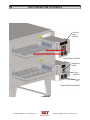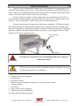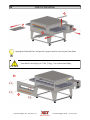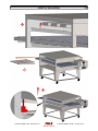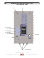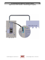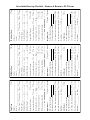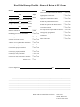
1
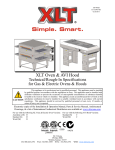
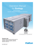
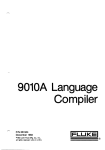
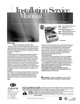
XD-9005A EL-SWB1-HB 02/22/2012 XLT Electric Oven & AVI Hood Installation & Operation Manual CAUTION This appliance is for professional use by qualified personnel. This appliance must be installed by qualified persons in accordance with the regulations in force. This appliance must be installed with sufficient ventilation to prevent the occurrence of unacceptable concentrations of substances harmful to health in the room in which it is installed. This appliance needs an unobstructed flow of fresh air for satisfactory operation & must be installed in a suitably ventilated room in accordance with current regulations. This appliance should be serviced by qualified personnel at least every 12 months or sooner if heavy use is expected. Current versions of this manual, Rough-In Specifications, Parts & Service Manual, Architectural Drawings, & a list of International Authorized Distributors are available at: www.xltovens.com For use with the following XLT Electric Oven Versions: Standard (S) B1 World (W) B1 For use with the following AVI Electric Hood Versions: Standard (S) B World (W) B 2000887 US: 888-443-2751 XLT Ovens PO Box 9090 Wichita, Kansas 67277 FAX: 316-943-2769 INTL: 316-943-2751 WEB: www.xltovens.com WARNING & SAFETY INFORMATION 2 SAFETY DEPENDS ON YOU WARNING Improper installation, adjustment, alteration, service or maintenance can cause property damage, injury, or death. Read the installation, operating and maintenance instructions thoroughly before installing, using, or servicing this equipment. FOR YOUR SAFETY Do not store or use gasoline or other flammable liquids or vapors in the vicinity of this or any other appliance. WARNING Do not restrict the flow of ventilation air to the unit. Provide adequate clearance for operating, cleaning, and maintaining the unit when in the installed position. Keep the area free and clear of combustible material. DO NOT SPRAY AEROSOLS IN THE VICINITY OF THIS APPLIANCE WHILE IT IS IN OPERATION. Ovens are certified for installation on combustible floors. Electrical schematics are located inside the control box of the oven and in this manual. Disconnect input power to the unit before performing any maintenance. This unit requires a ventilation hood. The installation must conform to local codes. This unit must be operated by the same voltage, phase, & frequency of electrical power as designated on the nameplate label located on the side of the unit. Minimum clearances must be maintained from combustible & non-combustible construction materials. Follow all local codes when installing this unit. Follow all local codes to electrically ground the unit. Appliance is not to be cleaned with high pressure water. XLT ovens are certified for use in stacks of up to three (3) units of XLT products. Integration of other manufacturer’s products into an oven stack is not recommended, & will void any warranties. XLT Ovens assumes no liability for mixed product applications. Failure to call XLT Customer Service at 1-888-443-2751 prior to contacting a repair company voids any & all warranties. PLEASE RETAIN THIS MANUAL FOR FUTURE REFERENCE. XLT Ovens has spent millions of dollars designing and testing our products as well as developing Installation & Operation Manuals. These manuals are the most complete and easiest to understand in the industry. However, they are worthless if they are not followed. We have witnessed store operators and building owners lose many thousands of dollars in lost revenue due to incorrect installations. We highly recommend you follow all instructions given in this manual as well as follow best practices in plumbing, electrical, and HVAC building codes. Technical Support US: 888-443-2751 Technical Support INTL: 316-943-2751 WARNING & SAFETY INFORMATION 3 Definitions & Symbols A safety instruction (message) includes a “Safety Alert Symbol” & a signal word or phrase such as WARNING or CAUTION. Each signal word has the following meaning: HIGH VOLTAGE This symbol indicates high voltage. It calls your attention to items or operations that could be dangerous to you & other persons operating this equipment. Read the message & follow the instructions carefully. Indicates a potentially hazardous situation that, if not avoided, can result in serious injury or death. WARNING Indicates a potentially hazardous situation, that if not avoided, can result in minor to moderate injury or serious damage to the product. The situation described in the CAUTION may, if not avoided, lead to serious results. Important safety measures CAUTION are described in CAUTION (as well as WARNING), so be sure to observe them. NOTE TIP Notes indicates an area or subject of special merit, emphasizing either the product’s capability or common errors in operation or maintenance. Tips give a special instruction that can save time or provide other benefits while installing or using the product. The tip calls attention to an idea that may not be obvious to first-time users of the product. Technical Support US: 888-443-2751 Technical Support INTL: 316-943-2751 4 WARRANTY - US & Canada XLT warrants gas ovens manufactured after April 1, 2009 utilizing quietFIRE™ burners and all electric ovens manufactured after April 1, 2011 to be free from any defect in material and workmanship under normal use for five (5) years from the date of original purchase by the end user, and further warrants main fan blades, conveyor shafts, and conveyor bearings for ten (10) years. XLT further warrants all ovens to be free from rust for ten (10) years from the date the equipment is originally purchased. XLT warrants AVI hoods to be free from any defect in material and workmanship under normal use for two (2) years from the date of original purchase by the end user. In the event of a part failure, XLT will furnish a replacement part and pay for all labor associated with the replacement of the part if, upon inspection, XLT determines that the part is defective. This warranty is extended to the original end user purchaser and is not transferable without prior written consent of XLT. Damages are limited to the original purchase price. DUTIES OF THE OWNER: The owner must inspect the oven and crates at time of receipt. Damage during shipment is to be immediately reported to the carrier and also to XLT. The oven must be operated in accordance with the written instructions furnished with the unit. This warranty shall not excuse the owner from properly maintaining the oven in accordance with the written instructions furnished with the unit. A copy of the “Oven Initial Start-Up Checklist” must be filled out and returned to XLT Ovens and the Authorized Distributor when the unit is initially installed, and/or when the unit is removed and installed in another location. The gas, electric, and HVAC utilities must be connected to the oven and installed by locally licensed contractors. Failure to contact XLT Ovens prior to contacting a repair company for warranty work voids any and all warranties. WHAT IS NOT COVERED: The following items are not covered by this warranty: Freight damage Any part that becomes defective because of utility services (power surges, high or low voltages, high or low gas pressure or volume, contaminated fuel, or improper utility connections) Conveyor belts Filters Exhaust Fans Light Bulbs Normal maintenance or adjustments This warranty shall not apply if the oven or any part is damaged as a result of accident, casualty, alteration, misuse, abuse, improper cleaning, improper installation, improper operation, natural disasters, or man-made disasters. CLAIMS HANDLED AS FOLLOWS: Should any such defect be discovered, XLT must be notified. Upon notification, XLT will arrange for necessary repairs to be made by an authorized service agent. Denial of services upon the arrival of an authorized service agent will release XLT of any and all warranty obligations. Technical Support US: 888-443-2751 Technical Support INTL: 316-943-2751 LIMITED WARRANTY - INTERNATIONAL 5 XLT warrants gas ovens manufactured after January 1, 2011 utilizing quietFIRE™ burners and all electric ovens manufactured after April 1, 2011 to be free from any defect in material and workmanship under normal use for two (2) years from the date of original purchase by the end user. XLT warrants AVI hoods to be free from any defect in material and workmanship under normal use for one (1) year from the date of original purchase by the end user. In the event of a part failure, XLT will furnish a replacement part to the Authorized Dealer if, upon inspection, XLT determines that the part is defective. The Authorized Dealer will pay for all labor associated with the replacement of the part. This warranty is extended to the original end user purchaser and is not transferable without prior written consent of XLT. Damages are limited to the original purchase price. DUTIES OF THE OWNER: The owner must inspect the oven and crates at time of receipt. Damage during shipment is to be immediately reported to the carrier and also to XLT. The oven must be operated in accordance with the written instructions furnished with the unit. This warranty shall not excuse the owner from properly maintaining the oven in accordance with the written instructions furnished with the unit. A copy of the “Oven Initial Start-Up Checklist” must be filled out and returned to XLT Ovens and the Authorized Dealer when the unit is initially installed, and/or when the unit is removed and installed in another location. The gas, electric, and HVAC utilities must be connected to the oven and installed by locally licensed contractors. Failure to contact the Authorized Dealer prior to contacting a repair company for warranty work voids any and all warranties. WHAT IS NOT COVERED: The following items are not covered by this warranty: Freight damage Any part that becomes defective because of utility services (power surges, high or low voltages, high or low gas pressure or volume, contaminated fuel, or improper utility connections) Conveyor belts Filters Exhaust Fans Light Bulbs Normal maintenance or adjustments This warranty shall not apply if the oven or any part is damaged as a result of accident, casualty, alteration, misuse, abuse, improper cleaning, improper installation, improper operation, natural disasters, or man-made disasters. CLAIMS HANDLED AS FOLLOWS: Should any such defect be discovered, the Authorized Dealer must be notified. Upon notification, the Authorized Dealer will arrange for necessary repairs to be made by an authorized service agent. The Authorized Dealer will notify XLT Ovens of all discovered defects. Technical Support US: 888-443-2751 Technical Support INTL: 316-943-2751 6 RECEIVING & INSPECTION NOTIFY CARRIER OF DAMAGE AT ONCE Upon receiving of all goods shipped by a Common Carrier, check for any exterior damage that may indicate interior damage. If conditions permit, open all crates & do a full inspection for any damage while the delivery driver is still there. If there is damage, please note on the delivery receipt & call the carrier to make a freight damage claim within 24 hours of receipt. Failure to make a damage claim within the first 24 hours may void the opportunity to have the claim resolved. XLT Ovens wants you to be totally satisfied with every aspect of owning & using your oven & hood. Your feedback, both positive & negative, is very important to us as it helps us understand how to improve our products & our company. Our goal is to provide you with equipment that we can be proud to build & you can be proud to own. To receive technical support for the oven or hood you purchased, XLT has qualified customer service personnel that can provide assistance on any type of XLT oven problem you may experience. Customer Service is available 24/7/365 or visit www.xltovens.com. Installation of all electric appliances & ventilation exhaust hoods should only be performed by a qualified professional who has read & understands these instructions & is familiar with proper safety precautions. Read this manual thoroughly WARNING before installing or servicing this equipment. Save this Manual This document is the property of the owner of this equipment. XLT Ovens reserves the right to make changes in design & specifications, and/or make additions to or improvements to its product without imposing any obligations upon itself to install them in products previously manufactured. All Right Hand & Left Hand designations in this manual are from the point of view as if standing directly in front of the glass sandwich door. Revision History Table Revision A Comments Date New Release 02/22/2012 Technical Support US: 888-443-2751 Technical Support INTL: 316-943-2751 TABLE OF CONTENTS Warning & Safety Information..................................................................................................... 2 Warranty ....................................................................................................................................... 4 Oven & Hood Descriptions .......................................................................................................... 8 Oven Dimensions & Weights ..................................................................................................... 10 Oven Electrical Requirements .................................................................................................... 12 Oven Only Rough-In Specifications .......................................................................................... 13 Oven Assembly .......................................................................................................................... 14 Oven Installation ........................................................................................................................ 20 Oven Fire Suppression ............................................................................................................... 21 Oven Ventilation Requirements & Guidelines ........................................................................... 23 Oven Initial Start-Up .................................................................................................................. 24 Oven Operation .......................................................................................................................... 25 Oven Operator Controls ............................................................................................................. 26 Oven Cleaning ............................................................................................................................ 27 Oven Maintenance ...................................................................................................................... 31 Oven Troubleshooting ................................................................................................................ 32 Hood Description ....................................................................................................................... 35 Hood Dimensions & Weights..................................................................................................... 36 Hood Electrical Requirements.................................................................................................... 38 Hood Electrical Connections ...................................................................................................... 40 Hood Rough-In Specifications ................................................................................................... 53 Hood Exhaust Flow Rates .......................................................................................................... 54 Hood Installation ........................................................................................................................ 56 Hood Initial Start-Up .................................................................................................................. 75 Hood Operator Controls ............................................................................................................. 76 Hood Valance Kit ....................................................................................................................... 77 Hood Duct Wrap Kit .................................................................................................................. 80 Hood Cleaning ............................................................................................................................ 81 Hood Troubleshooting ................................................................................................................ 82 Variable Frequency Drive Manual Mode ................................................................................... 83 Electrical Schematics ................................................................................................................. 84 Certifications .............................................................................................................................. 95 Oven Start-Up Checklist ............................................................................................................ 97 Hood Start-Up Checklist ............................................................................................................ 99 Technical Support US: 888-443-2751 Technical Support INTL: 316-943-2751 7 8 DESCRIPTIONS This manual covers the following XLT Oven & AVI Hood models: Ovens Hoods Standard World Standard World XLT-1832B1-EL-S XLT-1832B1-EL-W AVI-1832B-EL-S AVI-1832B-EL-W XLT-1855B1-EL-S XLT-1855B1-EL-W AVI-1855B-EL-S AVI-1855B-EL-W XLT-2440B1-EL-S XLT-2440B1-EL-W AVI-2440B-EL-S AVI-2440B-EL-W XLT-3240B1-EL-S XLT-3240B1-EL-W AVI-3240B-EL-S AVI-3240B-EL-W XLT-3255B1-EL-S XLT-3255B1-EL-W AVI-3255B-EL-S AVI-3255B-EL-W XLT-3855B1-EL-S XLT-3855B1-EL-W AVI-3855B-EL-S AVI-3855B-EL-W The first 2 digits of the model number represent the conveyor width and the last two digits indicate the bake chamber length. The “EL” designates electrically heated ovens. The ovens may be used in a single, double, or triple stack configuration. All models have a single control box, which can be mounted on either the right-hand or left-hand side, and are heated by electric elements. All models can be configured for a split belt conveyor. OVEN DESCRIPTION Food product is placed on the stainless steel wire conveyor belt on one side of the oven. The conveyor then transports the food through the bake chamber at a user-controlled speed. This provides repeatable and uniform food cooking. The conveyors can be easily configured to move either left-to-right or right-to-left. A large center sandwich door allows the introduction or removal of food items for cooking at shorter times. Precise temperatures are user adjustable and maintained by a digital control. An easily removable front panel allows the full cleaning of the oven interior. All exposed oven surfaces both exterior and interior are stainless steel. The conveyor is a one piece design and is removed from the side which has the control box. No tools are required for disassembly and cleaning of the conveyor or oven interior. The oven itself is mounted on lockable swivel casters for easy moving and maintenance. Accessories such as extended conveyor shelves, base shelves, cool fronts, fire suppression components, and perforated crumb trays are available from XLT. In addition, moving equipment such as carts and lifting jacks are available to help install and move ovens. Please contact XLT Ovens or your Authorized Distributor for more information. Technical Support US: 888-443-2751 Technical Support INTL: 316-943-2751 9 OVEN DESCRIPTION Sandwich Door Oven Lid Conveyor Control Box Crumb Tray Front Panel Knob Product Stop Front Panel Locking Swivel Caster Data Plate Control Box Lid Control Switch Control Panel Chain Guard Technical Support US: 888-443-2751 Technical Support INTL: 316-943-2751 10 OVEN DIMENSIONS Technical Support US: 888-443-2751 Technical Support INTL: 316-943-2751 OVEN DIMENSIONS & WEIGHTS SINGLE OVEN 1832 1855 2440 3240 3255 3855 DOUBLE STACK 1832 1855 2440 3240 3255 3855 TRIPLE STACK 1832 1855 2440 3240 3255 3855 A B C D E F G 18 [457] 18 [457] 24 [610] 32 [813] 32 [813] 38 [965] 32 [813] 55 [1397] 40 [1016] 40 [1016] 55 [1397] 55 [1397] 47 1/4 [1200] 47 1/4 [1200] 53 1/4 [1353] 61 1/4 [1556] 61 1/4 [1556] 67 1/4 [1708] 70 [1778] 93 [2362] 78 [1981] 78 [1981] 93 [2362] 93 [2362] 67 1/4 [1708] 90 1/4 [2292] 75 1/4 [1911] 75 1/4 [1911] 90 1/4 [2292] 90 1/4 [2292] 42 3/4 [1086] 42 3/4 [1086] 42 3/4 [1086] 42 3/4 [1086] 42 3/4 [1086] 42 3/4 [1086] 32 [813] 32 [813] 32 [813] 32 [813] 32 [813] 32 [813] A B C D E F 18 [457] 18 [457] 24 [610] 32 [813] 32 [813] 38 [965] 32 [813] 55 [1397] 40 [1016] 40 [1016] 55 [1397] 55 [1397] 47 1/4 [1200] 47 1/4 [1200] 53 1/4 [1353] 61 1/4 [1556] 61 1/4 [1556] 67 1/4 [1708] 70 [1778] 93 [2362] 78 [1981] 78 [1981] 93 [2362] 93 [2362] 67 1/4 [1708] 90 1/4 [2292] 75 1/4 [1911] 75 1/4 [1911] 90 1/4 [2292] 90 1/4 [2292] A B C D 18 [457] 18 [457] 24 [610] 32 [813] 32 [813] 38 [965] 32 [813] 55 [1397] 40 [1016] 40 [1016] 55 [1397] 55 [1397] 47 1/4 [1200] 47 1/4 [1200] 53 1/4 [1353] 61 1/4 [1556] 61 1/4 [1556] 67 1/4 [1708] 70 [1778] 93 [2362] 78 [1981] 78 [1981] 93 [2362] 93 [2362] 11 H J N/A N/A N/A N/A N/A N/A N/A N/A N/A N/A N/A N/A G H J 62 3/4 [1594] 62 3/4 [1594] 62 3/4 [1594] 62 3/4 [1594] 62 3/4 [1594] 62 3/4 [1594] 32 [813] 32 [813] 32 [813] 32 [813] 32 [813] 32 [813] 52 [1321] 52 [1321] 52 [1321] 52 [1321] 52 [1321] 52 [1321] E F G H J WEIGHT 67 1/4 [1708] 90 1/4 [2292] 75 1/4 [1911] 75 1/4 [1911] 90 1/4 [2292] 90 1/4 [2292] 67 3/4 [1721] 67 3/4 [1721] 67 3/4 [1721] 67 3/4 [1721] 67 3/4 [1721] 67 3/4 [1721] 17 [432] 17 [432] 17 [432] 17 [432] 17 [433] 17 [433] 37 [940] 37 [940] 37 [940] 37 [940] 37 [941] 37 [941] 57 [1448] 57 [1448] 57 [1448] 57 [1448] 57 [1448] 57 [1448] 1216 [552] 1624 [737] 1386 [629] 1617 [733] 1964 [891] 2156 [978] N/A N/A N/A N/A N/A N/A WEIGHT 477 [216] 624 [283] 543 [246] 629 [285] 757 [343] 829 [376] WEIGHT 863 [391] 1141 [518] 981 [445] 1142 [518] 1380 [626] 1513 [686] NOTE: All dimensions in inches [millimeters], ± 1/4 [6], unless otherwise noted. All weights in pounds [kilograms] unless otherwise noted. Technical Support US: 888-443-2751 Technical Support INTL: 316-943-2751 12 OVEN ELECTRICAL REQUIREMENTS Electric Oven Electrical Requirements Per EACH Oven Oven Model 1832 1855 2440 3240 3255 3855 STANDARD WORLD Volts AC Amps Hertz Volts AC Amps Hertz 208/240 44/38 24 208/240/480 88/77/38 48 208/240/480 75/65/33 41 60 380 50 208/240/480 75/65/33 41 208/240/480 88/77/38 48 208/240/480 88/77/38 48 4 Wire Service - L1, L2, L3 5 Wire Service - L1, L2, L3 +1 Ground (per oven) N +2 Grounds (per oven) ALL Phase KW 16 32 27 3 27 32 32 FOR EACH OVEN: A separate circuit breaker must be provided for each oven deck. Electrical connections must be accessible when the ovens are in the installed position. Electrical connections must meet all local code requirements. Ensure ovens are grounded per local codes. Incoming Power Connection Point Ground Lug Control Box Rear - Standard Incoming Power Connection Point Ground Lug Earth Ground Lug Control Box Rear - World Technical Support US: 888-443-2751 Technical Support INTL: 316-943-2751 OVEN ONLY ROUGH-IN SPECIFICATIONS 13 6.00 [152] From back of oven to wall NOTE Utilities must be easily accessible when the ovens are in the installed position. Do not install utilities behind the ovens. Disconnect Switch Breaker Panel (Shown for reference only) NOTE All installations must conform to local building and mechanical codes. It is required that the ovens be placed under a ventilation hood to provide exhaust ventilation and adequate air supply. Technical Support US: 888-443-2751 Technical Support INTL: 316-943-2751 14 OVEN ASSEMBLY Base Assembly - Triple Stack Technical Support US: 888-443-2751 Technical Support INTL: 316-943-2751 OVEN ASSEMBLY Base Assembly - Single & Double Stack Technical Support US: 888-443-2751 Technical Support INTL: 316-943-2751 15 16 OVEN ASSEMBLY WARNING & SAFETY INFORMATION XLT ovens can easily be moved and stacked with the proper lifting equipment. The use of XLT approved lifting equipment is highly recommended. Contact XLT for more information. WARNING These ovens are heavy & can tip or fall causing bodily injury. NEVER place any part of your body beneath any oven that is suspended by the lifting jacks. A crush hazard exists if the oven falls or slips. DO NOT place your hands on the lifting jack vertical pole beneath the jack’s winch. As the jack’s winch descends when you turn the jack handle, a pinch point is created between the winch & the pole. BE CAREFUL when rolling the oven on the cart, especially when going up or down ramps & over bumps. Leave the straps/banding on until the oven is near the assembly area. CAUTION WARNING Make sure that the notch on tube of the winch assembly is aligned with the pin in the tripod base as shown. These alignments are important and keep the jack aligned properly. Check for smooth operation. The cable should not be pinched and should pass smoothly over the pulley on top of the pole assembly. Inspect cable prior to each use. If cable is frayed or shows signs of excessive wear and tear, DO NOT USE until cable is replaced. At a minimum replace the cable annually with wire rope that meets or exceeds the jack manufacturer’s specifications. Do not exceed the stated capacity of the jack. 1 Technical Support US: 888-443-2751 Technical Support INTL: 316-943-2751 OVEN ASSEMBLY 17 2 NOTE The Lifting Pipe hole, marked for the appropriate oven size, must be installed closest to the control box. 3 Technical Support US: 888-443-2751 Technical Support INTL: 316-943-2751 18 OVEN ASSEMBLY Stacking the Ovens Failure to engage the Lifting Jacks into the Lifting Pipe properly and completely will result in damage, injury, or death from a falling oven. WARNING WARNING Both jacks should be raised in unison, otherwise they may bind and a dangerous situation will develop. Do not put any part of yourself under the oven at any time. The Oven is top heavy. Be careful. 5 4 6 Technical Support US: 888-443-2751 Technical Support INTL: 316-943-2751 OVEN ASSEMBLY Stacking the Ovens Technical Support US: 888-443-2751 Technical Support INTL: 316-943-2751 19 20 OVEN INSTALLATION Physical Location & Spacing Requirements These ovens are suitable for installation on either combustible or non-combustible floors, and adjacent to either combustible or non-combustible walls. The motor cover is designed to provide the proper clearance to the back of the oven. The minimum side clearances are 6in. / 150mm, measured from the end of the conveyor. All installations must conform to local building and mechanical codes. NOTE Restraint Because all ovens are equipped with casters, all installations must be configured with a restraint to limit the movement of the oven without depending on the electric power supply cord to limit the oven movement. One (1) restraint kit, which includes one (1) eye bolt, (1) stainless steel clip & a cable, is required for each oven stack, regardless if used on a single, double, or triple configuration. The clip should be installed in the lowest hole of the back wall on the control end of the lowest oven in the stack. The lag eye bolt must be installed into a structural member of a wall or the floor. It is the owner’s responsibility to ensure the restraint is installed correctly. Upon completion of performing any service or cleaning functions that require removal of the restraint, insure that it is correctly re-attached to the oven. Technical Support US: 888-443-2751 Technical Support INTL: 316-943-2751 OVEN FIRE SUPPRESSION 21 The requirement for fire suppression systems vary by location and the authority having jurisdiction. If you are required to install fire suppression on your oven, a pre-assembled piping kit is available that utilizes pre-existing holes that simplify installation and future service. This design has been tested and approved to successfully comply with fire suppression codes. It uses only two (2) nozzles per bake chamber, and allows crumb trays, chain guards, and all other accessories to be easily removed. The kit does not interfere with any operations or maintenance. A flexible hose that connects the oven to the rest of the fire suppression system is also available. This allows easy movement of the oven(s) for cleaning and maintenance. Technical Support US: 888-443-2751 Technical Support INTL: 316-943-2751 22 OVEN FIRE SUPPRESSION Technical Support US: 888-443-2751 Technical Support INTL: 316-943-2751 OVEN VENTILATION REQUIREMENTS & GUIDELINES 23 Ventilation Requirements A powered ventilation hood is required to remove heat and vapors. Some provision must be made to replenish the amount of air that is extracted from the building. The hood and HVAC installation must meet local building and mechanical codes. Requirements vary throughout the country depending upon location. Proper ventilation is the oven owner’s responsibility. The AVI Hood system is designed to meet all requirements for XLT ovens and it is our recommendation that this system be used. Ventilation Guidelines Obtain information from the authority having jurisdiction to determine the requirements for your installation. Your ventilation hood supplier and HVAC contractor should be contacted to provide guidance. An air balance test is highly recommended, performed by a licensed contractor. A properly engineered and installed ventilation hood and HVAC system will expedite approval, reduce all maintenance costs, and provide a more comfortable working environment. XLT also recommends that the operator switches for the ovens and the operator switch for the exhaust fan be interlocked so that the exhaust fan gets energized whenever the ovens are turned on. For more information, see the following links at xltovens.com: Kitchen Ventilation Design Guide 1 Kitchen Ventilation Design Guide 2 Kitchen Ventilation Design Guide 3 Kitchen Ventilation Design Guide 4 Ventilation Performance Test After the oven and ventilation hood have been installed and are operating, a smoke candle can be used to “see” if the heat and vapors are being completely extracted. The test procedure is outlined below: The oven must be operating at 450º-500ºF / 232º-260ºC. The conveyor must be turned off. The ventilation hood exhaust fan must be turned on. Put a smoke candle in a pan on the conveyor belt at the center of the oven. Observe the smoke pattern coming out of the oven. Repeat the smoke candle test for each oven, as well as when all ovens are operating. The ventilation hood must capture all of the smoke from the oven. After the exhaust fan has been adjusted to completely capture and contain the heat, there needs to be a corresponding amount of make up air (MUA) introduced into the building to offset the amount of air volume being removed. An air balance test can determine the proper amount of make-up air flow rates. Technical Support US: 888-443-2751 Technical Support INTL: 316-943-2751 24 OVEN INITIAL START-UP All ovens are tested at the factory for functional operation. Operation is verified and adjustments are made to ensure proper function. However, field conditions are sometimes different than factory conditions. It is necessary to have an authorized service technician verify operation and make field adjustments if needed. The Oven Initial Start-Up Checklist, found at the end of this manual, must be completed (both sides) at time of installation, signed by the Customer and returned to XLT Ovens and the Authorized Distributor to initiate Warranty Policy. If the Start-Up Checklist is not filled out completely and returned to XLT Ovens, then the Warranty will not be honored. Technical Support US: 888-443-2751 Technical Support INTL: 316-943-2751 OVEN OPERATION 25 This oven is not capable of being safely placed in operation in the event of a power failure. No attempt should be made to operate this oven during power CAUTION failure. Set Point Temperature 1 Actual Temperature 2 Temperature Control Push and Hold 3 4 Conveyor Control Push and Hold Conveyor Belt Times (Min:Sec) Oven Models All MINIMUM MAXIMUM 1:30 17:00 Oven Operating Temperature Range Oven Models MINIMUM MAXIMUM All 400° F 205° C 590° F 310° C Technical Support US: 888-443-2751 Technical Support INTL: 316-943-2751 26 OVEN OPERATOR CONTROLS Conveyor Speed Controls Control Panel Split Belt Temperature Control Circuit Breakers Fans & Filters Control Panel Standard Belt Technical Support US: 888-443-2751 Technical Support INTL: 316-943-2751 OVEN CLEANING 27 Your XLT oven is constructed of stainless steel. Most commercial cleaning agents may be used safely on all stainless steel surfaces. Check application restrictions on product label prior to usage. Observe recommended precautionary and safety measures as dictated by the product manufacturer. Do not use caustic cleaner on the conveyor bearings. Do not use abrasive cleaners or abrasive pads as they can scratch stainless steel surfaces. Areas with heavy buildup should be sprayed and allowed to soak for up to 5 minutes prior to wiping clean. Always wipe with the “grain” of the surface to maintain appearance. The most critical item to be cleaned is the filter on the cooling fans. The filters are held in place by the stainless steel fan guard/filter mount & can be washed several times. Regular cleaning of the cooling filters is important to maintain air circulation within the control box. Depending upon store conditions, this filter should be cleaned weekly or as it gets clogged with dust. Please contact XLT Ovens for replacement parts. Fan Guard/Filter Holders Fan Filters WARNING Oven must be cool and the electric cord unplugged before any cleaning or maintenance is done. If the oven is to be removed from its installed location for cleaning or servicing, the following procedure is to be followed: CAUTION 1. Shut off main electrical disconnect. 2. Unplug electric cord, if equipped. 3. Unlock casters. 4. Disconnect restraint. 5. When servicing or cleaning is complete, move oven to original location. 6. Connect restraint. 7. Lock casters. 8. Plug in electric cord, if equipped. 9. Turn on main electrical disconnect. 10. Follow normal starting instructions. Technical Support US: 888-443-2751 Technical Support INTL: 316-943-2751 28 OVEN CLEANING 2 1 3 1 Opening the Sandwich Door will provide a grip location for removing the Front Panel. TIP Front Panels can weigh up to 75 lbs. [34 kg]. Use caution when lifting. CAUTION 4 5 Technical Support US: 888-443-2751 Technical Support INTL: 316-943-2751 OVEN CLEANING 6 7 8 Technical Support US: 888-443-2751 Technical Support INTL: 316-943-2751 29 30 OVEN CLEANING 9 10 DO NOT spray liquid cleaning agents in the slots and holes in the following locations: Rear of Control Box Underneath Control Box CAUTION Main Fan Motor Cover Technical Support US: 888-443-2751 Technical Support INTL: 316-943-2751 OVEN MAINTENANCE 31 As with any appliance, periodic maintenance is required. Many factors affect this schedule such as product mix and hours of usage. An example schedule is included. Oven Maintenance Schedule Daily Weekly Monthly SemiAnnual Cleaning Empty Crumb Trays Wipe down Front, Sides, & Top Wipe down Control Box & Control Panel Clean or Fan Filters Remove large debris from Conveyor Wipe down Motor Cover Clean Sandwich Window Remove debris from Finger Outers Remove debris from inside Bake Chamber Remove debris from Main Fan Motor Clean Finger Outers Clean inside Bake Chamber Clean Conveyor Assembly □ □ □ Check Fan Filters for dirt Check Conveyor Wire Belt for Stretch Check Conveyor Drive Roller Chain for Stretch □ As Needed □ □ □ □ □ □ □ □ □ Inspection □ □ Adjust Conveyor Wire Belt □ Lubricate Conveyor Drive Roller Chain □ Replace Fan Filters As Needed Contact a factory representative or a local service company to perform all other maintenance and repairs. WARNING Oven must be cool and the electric cord unplugged before any cleaning or maintenance is done. Contact a factory representative or a local service company to perform all other maintenance & repairs. Technical Support US: 888-443-2751 Technical Support INTL: 316-943-2751 32 OVEN TROUBLESHOOTING Proper Cooking Experimentation is about the only way to determine proper time and temperature settings. While a pizza may look perfectly cooked on the outside, the inside may be undercooked. A thermometer is necessary to determine if food items are being properly cooked. Most health departments have rules and regulations that establish minimum temperatures for internal food temperatures. Most operators want to cook foods as fast as possible in order to serve more customers per hour. However, cooking foods slower is the only way to achieve a proper internal temperature. If your food products look acceptable on the outside, but have an internal temperature that is too low, then lowering the temperature and decreasing the belt speed (thereby increasing the cook time), will be necessary. Several factors may affect the cooking performance and characteristics: 1. 2. 3. 4. 5. 6. 7. 8. 9. Oven temperature (generally affects color) Conveyor speed (generally affects doneness) Finger arrangement Altitude Pans versus screens Dough thickness Cheese type Raw ingredient temperature (frozen?) Quantity of toppings XLT ovens can be configured to cook a wide variety of food items. This is accomplished by arranging the fingers to control the baking characteristics. Generally speaking, most cooking is a “bottom up” process. The hot air from the bottom row of fingers has to go through the conveyor (a distance of about 2” / 50.8mm), heat the pan or screen, and then actually cook raw dough. The hot air from the top, on the other hand, basically only has to melt cheese and re-heat precooked toppings. Consequently, most operators will use the oven with the fingers arranged so that a lot more air is directed to the bottom of the pizza than to the top. There are places for an equal number of fingers above and below the conveyor. Available are finger cover plates that have six rows of holes, four rows of holes, two rows of holes, and no holes (or blank cover plates). A typical finger arrangement might have most or even all fingers on the bottom “full open”, that is fingers with all six rows of holes, and only two or three fingers on top with four or six rows of holes. The top fingers can be arranged in a symmetrical pattern or can be shifted asymmetrically to either the entrance or exit end of the conveyor. We encourage you to experiment by trying different finger arrangements, temperatures and belt speeds. XLT Ovens can assist you with your oven/product configurations. Technical Support US: 888-443-2751 Technical Support INTL: 316-943-2751 OVEN TROUBLESHOOTING 33 Mechanical Function If your oven does not function properly, please verify the following conditions: 1. Verify that the power cord to the oven is connected and/or plugged in if equipped with a plug and receptacle. 2. Check to see that the circuit breakers in the building electrical service panel have not been tripped or turned off. 3. Check all circuit breakers on the oven control panel to ensure they have not been tripped. 4. Ensure proper voltage, amperage, and wire size. If your oven still does not function properly, XLT has qualified customer service personnel that can provide assistance on any type of XLT oven problem you may experience. Customer Service is available 24/7/365 at 888-443-2751, or visit www.xltovens.com. An interactive troubleshooting guide is available on the website. Technical Support US: 888-443-2751 Technical Support INTL: 316-943-2751 34 AVI HOOD INSTALLATION WARNING Check all local codes prior to installation. Special requirements may be necessary depending upon building material construction. It is the installing contractor’s responsibly to ensure that the structure the hood is to be hung from meets all codes and can carry the hood weight. Purchaser’s Responsibility It is the responsibility of the purchaser: Thoroughly review the floor plans and specifications. The exact location of the oven must be determined before installing the hood. To unload, uncrate, assemble, and install the hood to it’s intended location. To ensure that electric utilities are installed on site in accordance with local building codes and with the specifications in this manual. To see that electric utilities are connected properly by a qualified installer using the proper hardware. To ensure a qualified installer has performed an initial start-up procedure. Location should minimize long and twisted duct runs. Make efforts to have a straight clear path to the roof fan curb. All hood supporting structures must be strong enough to support the weight of the hood and shrouds. Refer to the Hood Dimensions & Weights page for weight. Maintain the proper clearances from combustible materials according to International Mechanical code (IMC), and National Fire Protection Agency (NFPA) 96, and local mechanical codes. Technical Support US: 888-443-2751 Technical Support INTL: 316-943-2751 AVI EXHAUST HOOD 35 HOOD DESCRIPTION Main Canopy Front Shroud Panel VFD Exhaust Fan Controller End Shroud Panel (size specific) The AVI Hood System consists of three (3) major parts; the Main Canopy, the Shrouds, and the Variable Frequency Drive (VFD) exhaust fan controller. The Main Canopy serves to collect and transmit heat to the exhaust fan. It houses filters, lights, and switches. The switches control both the hood and ovens. The main canopy size is dependent upon oven size. The Shrouds assist the efficiency of the main canopy by entrapping heat. They are configurable for either side or end loading or unloading, and are easily removable for cleaning and maintenance. The VFD converts input power to variable frequency three-phase output power to control the speed of the exhaust fan. All electric utilities for the hood and exhaust fan connect through the electrical box located on the rear of main canopy. The operator switches are located on the control panel on the front of main canopy, and interlock the function of the hood and oven(s). There are optional relays that provide interlocks for equipment such as, fire suppression, HVAC dampers, and/or dedicated MUA units. All AVI hoods are available pre-piped for fire suppression, allowing for simple, in-field installations. Technical Support US: 888-443-2751 Technical Support INTL: 316-943-2751 36 AVI HOOD DIMENSIONS Technical Support US: 888-443-2751 Technical Support INTL: 316-943-2751 AVI HOOD DIMENSIONS & WEIGHTS Oven Model 1832 1855 2440 3240 3255 3855 37 Hood Dimensions A B C 34 3/8 [873] 34 3/8 [873] 40 3/8 [1026] 48 3/8 [1229] 48 3/8 [1229] 54 3/8 [1381] 88 5/8 [2251] 111 5/8 [2835] 96 5/8 [2454] 96 5/8 [2454] 111 5/8 [2835] 111 5/8 [2835] 18 [457] 18 [457] 24 [610] 32 [813] 32 [813] 38 [965] D E 32 [813] 55 [1397] 40 [1016] 13 1/2 40 [343] [1016] 55 [1397] 55 [1397] F Hood Weights G H 30 5/8 [778] 30 5/8 [778] 33 5/8 12 69 5/8 [854] 37 5/8 [305] [1768] [956] 37 5/8 [956] 40 5/8 [1032] J 89 7/8 [2283] K 91 3/4 [2330] Single Double Triple 540 [245] 615 [279] 620 [281] 680 [308] 740 [336] 795 [361] 500 [227] 565 [256] 570 [259] 630 [286] 670 [304] 720 [327] 525 [238] 590 [268] 595 [270] 655 [297] 695 [315] 745 [338] NOTE: All dimensions in inches [millimeters], ± 1/4 [6], unless otherwise noted. All weights in pounds [kilograms] unless otherwise noted. Technical Support US: 888-443-2751 Technical Support INTL: 316-943-2751 38 AVI HOOD ELECTRICAL REQUIREMENTS Inputs into VFD Box AVI Hood Electric Utility Specifications # of Circuits Rating Purpose 1 230 VAC, 1 Phase, 50 Hz, 3 Amp VFD Controller Australian 1 230 VAC, 1 Phase, 50 Hz, 1 Amp Lights 1 208/240 VAC, 3 Phase, 60 Hz, 3 Amp VFD Controller Standard 1 120 VAC, 1 Phase, 60 Hz, 1 Amp Lights 1 230 VAC, 1 Phase, 50 Hz, 3 Amp VFD Controller World 1 230 VAC, 1 Phase, 50 Hz, 1 Amp Lights Outputs from VFD Box The AVI Hood system provides: Three (3) switching outputs for HVAC dampers and dedicated units One (1) 230 VAC, 10 Amp, variable frequency, three phase power output for the ventilation exhaust fan. Technical Support US: 888-443-2751 Technical Support INTL: 316-943-2751 AVI HOOD ELECTRICAL DESCRIPTION 39 VFD Control Box - Standard Terminal Strip (TS1) Grounding Block Terminal Strip (TS2) Manual Mode Relay (R5) MUA Damper Relay (R2) (optional) Manual Mode Relay (R6) MUA Damper Relay (R3) (optional) Manual Mode Relay (R7) MUA Damper Relay (R4) (optional) Circuit Breaker VFD Controller Manual Mode Switch #1 Manual Mode Switch #2 Oven/hood interface VFD Control Box (Cover removed) Technical Support US: 888-443-2751 Technical Support INTL: 316-943-2751 40 AVI HOOD ELECTRICAL CONNECTIONS Input Power to VFD Controller - Standard Voltage & Frequency Technical Support US: 888-443-2751 Technical Support INTL: 316-943-2751 AVI HOOD ELECTRICAL CONNECTIONS Input Power to Lights with VFD- Standard Voltage & Frequency Technical Support US: 888-443-2751 Technical Support INTL: 316-943-2751 41 42 AVI HOOD ELECTRICAL CONNECTIONS Power from VFD to Exhaust Fan - Standard Voltage & Frequency Technical Support US: 888-443-2751 Technical Support INTL: 316-943-2751 AVI HOOD ELECTRICAL CONNECTIONS Fire Alarm Relay - Standard Voltage & Frequency Option currently not available Technical Support US: 888-443-2751 Technical Support INTL: 316-943-2751 43 AVI HOOD ELECTRICAL CONNECTIONS 44 MUA Damper Relays - Single Output - Standard Voltage & Frequency MUA Unit Relay Customer Supplied Power In Power Out A1 A2 Neutral Supply from Breaker Panel 10 Amperes Maximum TS 1 TS 2 R1 R2 R3 Some wiring removed for clarity. See schematic for details. Technical Support US: 888-443-2751 Technical Support INTL: 316-943-2751 AVI HOOD ELECTRICAL CONNECTIONS 45 MUA Damper Relays - Multiple Output - Standard Voltage & Frequency MUA Unit Relay Customer Supplied Power In MUA Unit Relay Customer Supplied Power Power Out In A1 A2 MUA Unit Relay Customer Supplied Power Power Out In A1 A2 Power Out A1 A2 Neutral Supply from Breaker Panel 10 Amperes Maximum TS 1 TS 2 R1 R2 R3 Some wiring removed for clarity. See schematic for details. Technical Support US: 888-443-2751 Technical Support INTL: 316-943-2751 46 AVI HOOD ELECTRICAL CONNECTIONS VFD Control Box - World Terminal Strip (TS1) Grounding Block Terminal Strip (TS2) MUA Damper Relay (R2) (optional) MUA Damper Relay (R3) (optional) MUA Damper Relay (R4) (optional) Circuit Breaker VFD Controller Oven/hood interface VFD Control Box (Cover removed) Technical Support US: 888-443-2751 Technical Support INTL: 316-943-2751 AVI HOOD ELECTRICAL CONNECTIONS Input Power to VFD Controller - World Voltage & Frequency Technical Support US: 888-443-2751 Technical Support INTL: 316-943-2751 47 48 AVI HOOD ELECTRICAL CONNECTIONS Output Power from VFD to Exhaust Fan - World Technical Support US: 888-443-2751 Technical Support INTL: 316-943-2751 AVI HOOD ELECTRICAL CONNECTIONS Fire Alarm Relay - World (optional) Option currently not available Technical Support US: 888-443-2751 Technical Support INTL: 316-943-2751 49 AVI HOOD ELECTRICAL CONNECTIONS 50 MUA Damper Relays - Single Output - World Voltage & Frequency MUA Unit Relay Customer Supplied Power In Power Out A1 A2 Neutral Supply from Breaker Panel 10 Amperes Maximum TS 1 TS 2 R1 R2 R3 Some wiring removed for clarity. See schematic for details. Technical Support US: 888-443-2751 Technical Support INTL: 316-943-2751 AVI HOOD ELECTRICAL CONNECTIONS 51 MUA Damper Relays - Multiple Output - World Voltage & Frequency MUA Unit Relay Customer Supplied Power In MUA Unit Relay Customer Supplied Power Power Out In A1 A2 MUA Unit Relay Customer Supplied Power Power Out In A1 A2 Power Out A1 A2 Neutral Supply from Breaker Panel 10 Amperes Maximum TS 1 TS 2 R1 R2 R3 Some wiring removed for clarity. See schematic for details. Technical Support US: 888-443-2751 Technical Support INTL: 316-943-2751 52 AVI HOOD ELECTRICAL CONNECTIONS Input Power to Lights - Without VFD Controller Terminal Strip (TS1) Grounding Block Oven/hood interface Non-VFD Control Box (Cover removed) Technical Support US: 888-443-2751 Technical Support INTL: 316-943-2751 Technical Support US: 888-443-2751 Fire Suppression Service Panel 1/2” All-thread Supported by Unistrut (4 Locations) Duct Wrap (optional) Welded Duct Fan Curb Exhaust Fan Three Phase Power to Oven Drop Ceiling Ceiling Joist Roof Finished Floor 3 Phase Power to Hood Electrical Box HVAC Unit AVI HOOD ROUGH-IN SPECIFICATIONS 53 All structural members, electrical & fire suppression equipment shown for reference only. Technical Support INTL: 316-943-2751 54 AVI RECOMMENDED EXHAUST FLOW RATES Top Single X X Double X X Triple X X X Exhaust Flow Rates VOLUME (min. recommended) Switches On 18xx 24xx 32xx Middle Bottom 500 500 500 [14.16] [14.16] [14.16] 500 500 500 [14.16] [14.16] [14.16] 506 644 828 X [14.33] [18.24] [23.45] 506 644 828 X [14.33] [18.24] [23.45] 500 500 500 [14.16] [14.16] [14.16] 506 644 828 X [14.33] [18.24] [23.45] 766 975 1254 X [21.69] [27.61] [35.51] 506 644 828 X [14.33] [18.24] [23.45] 766 975 1254 X [21.69] [27.61] [35.51] 766 975 1254 X X [21.69] [27.61] [35.51] 766 975 1254 X X [21.69] [27.61] [35.51] 38xx 500 [14.16] 500 [14.16] 966 [27.35] 966 [27.35] 500 [14.16] 966 [27.35] 1463 [41.43] 966 [27.35] 1463 [41.43] 1463 [41.43] 1463 [41.43] 3 NOTE: All values are CFM [M /Min] unless otherwise noted. NOTE: Figures represent TOTAL VOLUME measured at the duct. In accordance with mechanical codes, make up air must be supplied. For commercial kitchen make up air, the amount is determined by the exhaust hood flow rate requirements & all other exhaust flow rate requirements in the kitchen. At a minimum, smoke candles must be used for a Capture & Containment (C&C) test. Refer to the Ventilation Requirements disclosed in the Oven section in this manual. A Test & Balance (TAB) report is recommended after installation has been completed. Below are the minimum items to be included is this report: Total airflow on all A/C, Make-Up Air (MUA), & exhaust systems. Airflow on each supply & exhaust grille. Airflows on exhaust hoods compared to design specifications. A final air balance report, with any corrections of issues found in the report, will help to insure that your building systems are functioning properly & efficiently. Refer to “Oven Ventilation Requirements & Guidelines” Technical Support US: 888-443-2751 Technical Support INTL: 316-943-2751 AVI RECOMMENDED EXHAUST FLOW RATES Top Single X X Double X X Triple X X X Exhaust Flow Rates VELOCITY (min. recommended) Switches On 18xx 24xx 32xx Middle Bottom 187.5 187.5 93.75 [57.15] [57.15] [28.58] 187.5 187.5 93.75 [57.15] [57.15] [28.58] 189.75 241.5 155.25 X [57.84] [73.61] [47.32] 189.75 241.5 155.25 X [57.84] [73.61] [47.32] 187.5 187.5 93.75 [57.15] [57.15] [28.58] 189.75 241.5 155.25 X [57.84] [73.61] [47.32] 287.25 365.625 235.125 X [87.55] [111.44] [71.67] 189.75 241.5 155.25 X [57.84] [73.61] [47.32] 287.25 365.625 235.125 X [87.55] [111.44] [71.67] 287.25 365.625 235.125 X X [87.55] [111.44] [71.67] 287.25 365.625 235.125 X X [87.55] [111.44] [71.67] 55 38xx 93.75 [28.58] 93.75 [28.58] 181.125 [55.21] 181.125 [55.21] 93.75 [28.58] 181.125 [55.21] 274.3125 [83.61] 181.125 [55.21] 274.3125 [83.61] 274.3125 [83.61] 274.3125 [83.61] NOTE: All values are FPM [M/Min] unless otherwise noted. NOTE: Figures represent VELOCITY measured at the Grease Filter. NOTE: Most building codes require 500 Feet per Minute velocity. Exhaust duct is 1 ft2. Check with your local building official for requirements. The VELOCITY readings above are obtained by holding an anemometer 3” away from the Grease Filter. Take several readings in different locations across the filters and average the results. Technical Support US: 888-443-2751 Technical Support INTL: 316-943-2751 56 AVI HOOD INSTALLATION Prepare Ovens - Remove Lid Screws - Two (2) Only Prepare Ovens - Control Box Closeout Bracket Conveyors have been removed for clarity Technical Support US: 888-443-2751 Technical Support INTL: 316-943-2751 AVI HOOD INSTALLATION Prepare Ovens - Front Shroud Brackets Technical Support US: 888-443-2751 Technical Support INTL: 316-943-2751 57 58 AVI HOOD INSTALLATION Prepare Ovens - Bottom Rail Bracket Prepare Ovens - Control Box Side Closeout Technical Support US: 888-443-2751 Technical Support INTL: 316-943-2751 AVI HOOD INSTALLATION Prepare Ovens - Rear Shroud Brackets Technical Support US: 888-443-2751 Technical Support INTL: 316-943-2751 59 60 AVI HOOD INSTALLATION Prepare Hood Technical Support US: 888-443-2751 Technical Support INTL: 316-943-2751 AVI HOOD INSTALLATION 61 Lifting Gear Setup AVI hoods can easily be moved and stacked with the proper lifting equipment. The use of XLT approved lifting equipment is highly recommended. Contact XLT for more information. Technical Support US: 888-443-2751 Technical Support INTL: 316-943-2751 62 AVI HOOD INSTALLATION Lifting Jack Setup WARNING Check for smooth operation. The cable should not be pinched & should pass smoothly over the pulley on top of the pole assembly. Inspect cable prior to each use. If cable is frayed or shows signs of excessive wear & tear, DO NOT USE until cable is replaced. At a minimum replace the cable annually with wire rope that meets or exceeds the jack manufacturer’s specifications. Do not exceed the stated capacity of the jack. Technical Support US: 888-443-2751 Technical Support INTL: 316-943-2751 AVI HOOD INSTALLATION 63 Stacking Hood on the Ovens Failure to engage the Lifting Jacks into the Lifting Pipe properly and completely will result in damage, injury, or death from a falling hood. WARNING WARNING Both jacks should be raised in unison, otherwise they may bind and a dangerous situation will develop. Do not put any part of yourself under the hood at any time. The hood is top heavy. Be careful. Technical Support US: 888-443-2751 Technical Support INTL: 316-943-2751 64 AVI HOOD INSTALLATION Hang Hood From Ceiling Joists All thread provided by others 69 5/8 ±1/8 [1768 ±3] Technical Support US: 888-443-2751 Technical Support INTL: 316-943-2751 AVI HOOD INSTALLATION 65 Install Grease Trays, Light Bulbs & Covers, and Grease Filters 1 2 3 4 5 6 Grease Tray Grease Filters Technical Support US: 888-443-2751 Filler Panel to be over Grease Tray Technical Support INTL: 316-943-2751 66 AVI HOOD INSTALLATION Install Shroud Hanging Brackets Technical Support US: 888-443-2751 Technical Support INTL: 316-943-2751 AVI HOOD INSTALLATION Install Corner Posts Technical Support US: 888-443-2751 Technical Support INTL: 316-943-2751 67 68 AVI HOOD INSTALLATION Install Bottom Rails Technical Support US: 888-443-2751 Technical Support INTL: 316-943-2751 AVI HOOD INSTALLATION Install Bottom Rails Technical Support US: 888-443-2751 Technical Support INTL: 316-943-2751 69 70 AVI HOOD INSTALLATION Install Control Box Upper Closeout Technical Support US: 888-443-2751 Technical Support INTL: 316-943-2751 AVI HOOD INSTALLATION Install Shroud Panels - Front and Ends 1 2 Technical Support US: 888-443-2751 Technical Support INTL: 316-943-2751 71 72 AVI HOOD INSTALLATION Install Back Shroud Panel Technical Support US: 888-443-2751 Technical Support INTL: 316-943-2751 AVI HOOD INSTALLATION 73 Install Hood Control Cord Assembly All hoods are outfitted with three (3) control cord outlets, regardless of how many XLT Ovens are installed. For a single oven use “Top” location. For a double stack use “Top” location for upper oven and “Bottom” location for lower oven, leaving “Middle” location open. Insert and lock each oven control cord into the designated location on the bottom of the hood control box. Technical Support US: 888-443-2751 Technical Support INTL: 316-943-2751 74 AVI HOOD INSTALLATION Connect Hood Control Cord Assembly Technical Support US: 888-443-2751 Technical Support INTL: 316-943-2751 AVI HOOD INITIAL START-UP 75 Variable Frequency Drive Adjustments All AVI Hoods are functionally tested at the factory. Operation is verified, and adjustments are made to ensure proper operation. However, field conditions are sometimes different than factory conditions. These variables make it necessary to have an authorized service technician verify operation and make field adjustments if needed. The following items must be checked and verified to meet the specifications and requirements stated in this manual prior to the hood being commissioned: Correct fan rotation. Balanced make-up air. The Initial Start-Up Checklist must be completed at time of installation, signed by the Customer and returned to XLT Ovens to initiate Warranty Policy. The VFD controller is adjusted at the factory to the values displayed in the chart below. VFD Controller Settings Switches On 1832, 1855 & 2440 3240, 3255 & 3270 3855 & 3870 Top Middle Bottom Single X 20 Hz 25 Hz 30Hz X 20 Hz 25 Hz 30Hz Double X 35 Hz 40 Hz 45 Hz X X 35 Hz 40 Hz 45 Hz X 20 Hz 25 Hz 30Hz X 30 Hz 35 Hz 40 Hz X 40 Hz 45 Hz 50 Hz Triple X X 30 Hz 35 Hz 40 Hz X X 40 Hz 45 Hz 50 Hz X X 40 Hz 45 Hz 50 Hz X X X 45 Hz 50 Hz 55 Hz Fire Suppression 60 Hz If you require either more or less air flow, follow these steps: 1. Turn at least one (1) oven switch ON. The VFD display should show the POWER and RUN LED lamps lit up, and a numeric value should appear in the window display. Window Display Function Store VFD Controller Display Technical Support US: 888-443-2751 Technical Support INTL: 316-943-2751 76 AVI HOOD OPERATOR CONTROLS 2. Press & hold the function key until <d001> displays. 3. Use the up / down arrows to reach <F001>. 4. Press the function key one (1) time. A frequency will display according to the switches that are ON per the chart below. 5. Turn all oven switches OFF. The display should read <0.0>. 6. Turn ON the oven switches to be set. For example, both Top and Bottom ovens, or Top oven only, or Bottom oven only, etc. 7. Press the Up/Down arrows until you reach the desired initial settings. 8. Press the store button once to store the new setting. 9. Repeat steps 6-8 for additional settings as needed. 10. When finished, turn all of the oven switches to the OFF position. 11. Press the <FUNC> key until <d001> appears in the display. 12. Press the <FUNC> one more time. The actual frequency will appear in the window display. 13. Press the <STR> button one time to store the values. The control switches are located on the front of the hood. NOTE When XLT Ovens are outfitted with AVI Hoods, the main switch on the oven is disabled and no longer operates. The switch on the AVI Hood overrides the oven switch. Hood Operation 1. Turn the light switch on. 2. Turn the desired oven switch on. Refer to the Oven start-up section for instructions on how to adjust temperature and conveyor speed. The oven(s), exhaust fan, and make-up air unit will be activated by this switch if the AVI Hood is installed according to this manual. 3. When additional oven switches are turned on, the VFD will automatically increase the exhaust fan speed. 4. When shutting down the ovens, turn the desired oven switch off. The make-up air unit will shut off. The ovens and exhaust fan will shut off after about 30 minutes. Refer to the Oven shutdown section for instructions. 5. Do not press the <STOP/RESET> switch on the Variable Frequency Drive itself. The RUN and POWER LED should stay lit all of the time. Technical Support US: 888-443-2751 Technical Support INTL: 316-943-2751 AVI HOOD VALANCE KIT (OPTIONAL) 77 The valance kit size is determined by AVI Hood size & distance from the finished floor to the installed drop ceiling height. The valance kit screws directly to the AVI Hood & does not require any structural support. All kits have provisions for hood fire suppression piping to pass through without modification. The plastic coating must be removed from all parts prior to installation. AVI Hood valance kits are available for different floor to ceiling heights. Contact XLT Ovens or your designated representative for more information. Technical Support US: 888-443-2751 Technical Support INTL: 316-943-2751 78 AVI HOOD VALANCE KIT (OPTIONAL) Install Valance Brackets Install Front & Back Panels Technical Support US: 888-443-2751 Technical Support INTL: 316-943-2751 AVI HOOD VALANCE KIT (OPTIONAL) Install Corner Panels Install End Panels Technical Support US: 888-443-2751 Technical Support INTL: 316-943-2751 79 80 AVI DUCT WRAP KIT (OPTIONAL) Technical Support US: 888-443-2751 Technical Support INTL: 316-943-2751 AVI HOOD CLEANING 81 Your AVI hood is constructed of stainless and aluminized steel. Check application restrictions on product label prior to usage. Observe recommended precautionary and safety measures as dictated by the product manufacturer. Do not use abrasive or caustic cleaners. Abrasive pads will scratch stainless steel surfaces. Areas with heavy buildup should be sprayed and allowed to soak for up to 5 minutes prior to wiping clean. Always wipe with the “grain” of the surface to maintain appearance. Hood Cleaning & Maintenance Schedule Daily Weekly Monthly SemiAs Required Annual Cleaning Wipe down Front, Sides, & Top Clean Light Globes Empty & Clean Grease Trays Clean Grease Filters Clean Duct and Exhaust Fan □ □ □ Check Indicator Lamp Check Grease Trays Check Grease Filters □ □ □ □ □ □ □ Inspection □ Adjust No Adjustments Necessary Lubricate No Lubrication Required Replace Light Bulbs □ Schedule provided as a guide only. Frequency of cleaning may vary as needed. Oven must be cool and the electric cord unplugged before any cleaning is done. WARNING Shroud Panels can weigh up to 60 lbs [27 kg]. Use caution when lifting. CAUTION DO NOT spray liquid cleaning agents in the slots & holes of the following locations: Hood electrical box (located on back of upper portion) VFD Controller CAUTION Back of control box Underneath control box Refer to the Hood Installation Section for disassembly and reassembly. Technical Support US: 888-443-2751 Technical Support INTL: 316-943-2751 82 AVI HOOD TROUBLESHOOTING Before troubleshooting the hood: 1. Make sure that the RUN lamp and POWER lamp are lit. 2. Check to see that the breaker in the service panel is not tripped. 3. Check to see that the breaker on the hood electrical box is not tripped. 4. Make sure the Switch Relocation Cords (SRC) are properly installed to the oven(s). 5. Check to see that the grease filters are clean & installed properly. 6. Check to see if the exhaust fan is rotating in the correct rotation. (applies to new installations) In the occurrence that the VFD controller has an ERROR Code displaying. Follow these steps to clear them. Error Codes: E01-E04 Inverter output was short circuited E05 motor overload is detected by electronic thermal function. E07 DC bus voltage exceeds a threshold E09 DC bus voltage is below a threshold E14 Ground fault detected between controller output and motor. Error Code Reset: Check VFD display for error code and record it. Clear error by pressing the <Stop Reset> button. Press the <Run> button to activate exhaust fan. Normal operation resumes with no error codes. If error codes return press the <Stop/Reset> key and call XLT service. If the corrective actions listed above do not correct the problem, then XLT has qualified customer service personnel that can provide assistance on any type of XLT Oven or AVI Hood problem you may experience. Customer Service is available at 888-443-2751 24/7/365, or visit www.xltovens.com. The website offers an interactive troubleshooting guide that can further assist in diagnosing problems. For repairs or maintenance of the fire suppression system and components, contact the local Ansul dealer or XLT for assistance. Technical Support US: 888-443-2751 Technical Support INTL: 316-943-2751 AVI VARIABLE FREQUENCY DRIVE (VFD) MANUAL MODE83 Standard Hoods ONLY The manual mode feature was designed to offer temporary operation of the exhaust fan at full power if the VFD controller fails. Manual mode should not be used for normal day-to-day operation and should only be utilized during emergency situations. The operator should return the VFD controller back to normal run mode as soon as the VFD is repaired or replaced. A key is supplied with the unit that unlocks both switches. The key must remain in keyed switch #1, Standard Mode, during normal operation. If the VFD fails, then follow these steps: 1. Rotate keyed switch #1 clockwise to the OFF position. 2. Wait until the VFD LED display and the POWER indicator lamp goes completely blank. NOTE: This may take up to 1 minute! Do not turn this switch off or on without allowing the VFD controller to completely shut down. CAUTION Failure to follow these instructions will result in damage to the VFD controller. After the VFD Controller display has gone off: 3. Remove the key from keyed switch #1 and insert it into keyed switch #2. 4. Rotate keyed switch #2 clockwise to the ON position. The exhaust fan should now operate at full speed, and can be turned ON & OFF from this switch. Exhaust fan will run at highest speed (60 Hz) when in manual mode. NOTE As soon as possible, ensure the VFD is either repaired or replaced. After the VFD is returned to operating condition, then follow these steps: 1. Rotate keyed switch #2 counter-clockwise to the OFF position. 2. Wait for the exhaust fan to come to a complete stop. 3. Wait 5 minutes. Ensure the exhaust fan has come to a complete stop before proceeding. Failure to follow these instructions will result in damage to the VFD controller. CAUTION After the exhaust fan has come to a complete stop: 4. Remove the key from keyed switch #2 & insert into keyed switch #1. 5. Rotate keyed switch #1 counter-clockwise to the ON position. 6. Press the green <RUN> button on the VFD Controller to reactivate standard mode. The VFD controller should illuminate & show <0.0>. Follow the steps outlined in the VFD Adjustments section of this manual. Technical Support US: 888-443-2751 Technical Support INTL: 316-943-2751 84 OVEN SCHEMATIC - STANDARD 1832-EL Standard 208/240 VAC Technical Support US: 888-443-2751 Technical Support INTL: 316-943-2751 OVEN SCHEMATIC - STANDARD 2440-EL, 3240-EL Standard 208/240 VAC Technical Support US: 888-443-2751 Technical Support INTL: 316-943-2751 85 86 OVEN SCHEMATIC - STANDARD 1855-EL, 3255-EL, 3855-EL Standard 208/240 VAC Technical Support US: 888-443-2751 Technical Support INTL: 316-943-2751 OVEN SCHEMATIC - STANDARD 2440-EL, 3240-EL Standard 480 VAC Technical Support US: 888-443-2751 Technical Support INTL: 316-943-2751 87 88 OVEN SCHEMATIC - STANDARD 1855-EL, 3255-EL, 3855-EL Standard 480 VAC Technical Support US: 888-443-2751 Technical Support INTL: 316-943-2751 OVEN SCHEMATIC - WORLD 1832-EL, World 380 VAC Technical Support US: 888-443-2751 Technical Support INTL: 316-943-2751 89 90 OVEN SCHEMATIC - WORLD 2440-EL, 3240-EL World 380 VAC Technical Support US: 888-443-2751 Technical Support INTL: 316-943-2751 OVEN SCHEMATIC - WORLD 1855-EL, 3255-EL, 3855-EL World 380 VAC Technical Support US: 888-443-2751 Technical Support INTL: 316-943-2751 91 92 AVI HOOD SCHEMATIC - STANDARD w/VFD Technical Support US: 888-443-2751 Technical Support INTL: 316-943-2751 AVI HOOD SCHEMATIC - WORLD w/VFD Technical Support US: 888-443-2751 Technical Support INTL: 316-943-2751 93 94 AVI HOOD SCHEMATIC w/o VFD Technical Support US: 888-443-2751 Technical Support INTL: 316-943-2751 APPENDIX A 95 Product Certifications and Applicable Codes Standard XLT Oven Certifications ¹: XLT Gas Ovens: 1. ANSI Z8311-2006/CSA 1.8-2006 Standard for Gas Food Service Equipment 2. ANSI /NSF 4-2006e Sanitation for Commercial Cooking Rethermillization & Powered Hot Food Holding & Transportation Equipment XLT Electric Ovens: 1. ANSI/UL197-CSA C22.2 Commercial Electric Appliances 2. ANSI /NSF 4-2006e Sanitation for Commercial Cooking Rethermillization & Powered Hot Food Holding & Transportation Equipment World XLT Oven Certifications¹ : XLT Gas Ovens: 1. EN 60335-2-42:2003 + A1:2008, used in conjunction with EN 60335-1:2002, Safety of Household Appliances and Similar Electrical Appliances 2. EN 60335 A11, A1:2004 + A12, A2:2006 + A1/C1:2007 + A13:2008 Low Voltage Directive (LVD) 3. EN 55014-1:2006 EN 61000-3-2:2006, EN 61000-3-3:1995 +A1:2001 +A2:2006, Electromagnetic Compatibility. (EMC) 4. EN 55014-2:1997 +A1:2001, Conducted Emissions, Surge Immunity 5. BS EN 203-1:2005+A1:2008, Standard for Safety of Gas Heated Catering Equipment 6. BS EN 203-2-1: 2005, Standard for Gas Heated Catering Equipment 7. 90/396/EEC. Gas Appliance Directive (GAD) XLT Electric Ovens: 1. EN 60335-2-42:2003 Safety of Household Appliances and Similar Electrical Appliances 2. EN 60335-1:2002 +A11, A1:2004 + A12, A2:2006 + A1/C1:2007 + A13:2008) Low Voltage Directive (LVD) 3. EN 6100-6-5 Electromagnetic Compatibility (EMC) 4. EN 55014-2:1997 +A1:2001, Conducted Emissions, Surge Immunity 5. EN 6100-6-1 EMC Immunity for residential, commercial & light industrial Technical Support US: 888-443-2751 Technical Support INTL: 316-943-2751 96 APPENDIX A Product Certifications and Applicable Codes - Continued 6. EN 5504-1 EMC house hold appliance electric tools & similar appliances 7. EN 6100-3-3 +A1+A2 Voltage fluctuation Standard & World AVI Hood Certifications ¹: 1. UL 710 Standard for Safety Exhaust Hoods for Commercial Cooking 2. ANSI/NSF 2-2009 Sanitation Food Equipment 3. ULC-S646, Standard for Exhaust Hoods and Related Controls for Commercial and Institutional Kitchens Australian XLT Oven Certifications ²: XLT Gas Ovens: (certificate 7373) 1. AS 4563-2004 Commercial Catering Gas Equipment 2. AS/NZS 3350.1:2002 Safety of Household & Similar Electrical Appliances. ¹ The noted certifications for XLT ovens and AVI Hood are performed and documented by Intertek Testing Services NA Inc. 165 Main Street, Cortland, NY 13045. Intertek is a nationally and internationally certified testing and accreditation agency. ² The certifications for Australia are administered and verified by the Australian Gas Association 2 Park Way, PO Box 122, BRAESIDE, VIC 3195 Technical Support US: 888-443-2751 Technical Support INTL: 316-943-2751 Oven Initial Start-up Checklist - Remove & Return to XLT Ovens Date of installation: _____________________________ Installed by: Company: Phone #: Installer: XLT installer: ____________Other: Oven Size: 1832 1855 2440 3240 3255 3270 3855 3870 Heat Source: Natural Gas LP Electric Facility Information Electrical Store Name: Electrical utilities accessible: Address: City: ____________________ State: _____ Zip:_______ Phone #: ______________________________________ Separate electrical circuit per oven: Yes No Yes No Electrical Supply (per oven): Volts Amps E-mail: _______________________________________ Hz Contact Person: ________________________________ Freestanding Strip Mall New construction Existing location Remodel Oven Location: Against wall In corner Island I&O Manual presented to store operator: Yes No Utilities present at installation: Electric Gas On-Site dough prep: Yes No Air-born contaminates: Flour Cornmeal Grease Phase Gas Ovens Only Inlet Pressures: Static: Dynamic: “WC “WC Gas Line Size: ___________ Teflon Tape: Yes No Address: ______________________________________ List all gas appliances in store (with gas requirements) Oven #1: Btu Oven #2: Btu Oven #3: Btu Water Heater: Btu Furnace: Btu Other: Btu Total gas requirements for store: Btu Regulator Capacity: Btu Meter Capacity: Btu City: ____________________ State: _____ Zip:_______ Shut off valve accessible after installation: Phone #: _______________ Cell: __________________ One shut off valve per oven: Other _________________________________ HVAC/Contractor Contact:_______________________ E-mail: _______________________________________ Restraint Cable installed on bottom oven: Yes No Drip Leg installed: Gas line purged of air prior to installation: Customer or store operator shown how to disassemble and clean ovens and hood: Test cook performed: Ovens ran for 30 min: All features explained: Yes No Yes No Yes No Yes No Damage to ovens or hood during shipment or installation: Fittings tested for gas leaks: Yes No Yes No Yes No Yes No Yes No Ventilation Hood manufacturer AVI Other (specify) _____________________________________________ Interlock system for non-AVI hood: Air balance test performed: Smoke test preformed: Customer Signature: Date: Return to: XLT Ovens PO Box 9090 Wichita, KS 67277 FAX: 316-943-2769 Yes No Yes No Yes No Front Belt Speed: _______min ______sec Front Belt Speed: _______min ______sec Yes No Yes No Yes No Yes No Yes No Yes No High Bias: ___________ Low Bias: ___________ Was Combination Valve adjusted: Low flame after temperature drop: Yes No Yes No N/A High Bias: ___________ Low Bias: ___________ Was Combination Valve adjusted: Low flame after temperature drop: Secondary Shutter Setting: Secondary Shutter Setting: Left Burner: Primary Shutter Setting: N/A High Bias: ___________ Low Bias: ___________ Was Combination Valve adjusted: Yes No Yes No Square Round Low flame after temperature drop: Primary Shutter Setting: Left Burner: High Bias: ___________ Low Bias: ___________ Was Combination Valve adjusted: Low flame after temperature drop: Secondary Shutter Setting: Secondary Shutter Setting: Right Burner: Primary Shutter Setting: Square Round ———-—— GAS OVENS ONLY —————— Fire Suppression Installed: Primary Shutter Setting: Right Burner: ———-—— GAS OVENS ONLY —————— Fire Suppression Installed: Fingers in proper location: Yes No Yes No Fingers in proper location: Set Point Temp: Left ________ Right _________ Conveyor Belt Direction: Proper Belt Tension: Set Point Temp: Left ________ Right _________ Conveyor Belt Direction: Proper Belt Tension: Back Belt Speed: _______min ______sec N/A Yes No L to R R to L Other Product: ____________________________ Other Product: ____________________________ Back Belt Speed: _______min ______sec Thin Crust Thick Crust Pan Screen Thin Crust Thick Crust Pan Screen N/A Yes No L to R R to L Serial #: __________________________________ N/A Serial #: __________________________________ Middle Oven Model #: __________________________________ N/A Model #: __________________________________ Top Oven N/A Yes No Yes No Yes No Yes No N/A High Bias: ___________ Low Bias: ___________ Was Combination Valve adjusted: Low flame after temperature drop: Secondary Shutter Setting: Primary Shutter Setting: Left Burner: High Bias: ___________ Low Bias: ___________ Was Combination Valve adjusted: Yes No Yes No Square Round Low flame after temperature drop: Secondary Shutter Setting: Primary Shutter Setting: Right Burner: ———-—— GAS OVENS ONLY —————— Fire Suppression Installed: Fingers in proper location: Set Point Temp: Left ________ Right _________ Conveyor Belt Direction: Proper Belt Tension: N/A Yes No L to R R to L Back Belt Speed: _______min ______sec Front Belt Speed: _______min ______sec Other Product: ____________________________ Thin Crust Thick Crust Pan Screen Serial #: __________________________________ Model #: __________________________________ Bottom Oven Oven Initial Start-up Checklist - Remove & Return to XLT Ovens Hood Initial Start-up Checklist - Remove & Return to XLT Ovens Model #: Serial #: VFD power supplied: Oven switch cords connected to VFD box: Volts Amps Hz Phase Light globes installed over bulbs: Height from bottom of hood to finished floor: Feet Exhaust fan purchased from XLT: Inches Length of duct run (from top of hood to fan): Feet Lights operate with switch: Exhaust fan operates with hood switches: Inches Correct fan rotation: Number of bends in duct run: ________45º ________ 90º Rating of exhaust fan: CFM Hood hung prior to oven installation: Hood hung to local codes: Switches face front of ovens: VFD box cover replaced after installation: All shroud panels properly installed: Grease filters properly installed: Grease trays properly installed: Crumb trays easily removable: Oven power cords connected to VFD box: Electric Oven Customer Signature: Yes No Yes No Yes No Yes No Yes No Yes No Yes No Yes No Yes No N/A Fire suppression relay in VFD box utilized: VFD properly programmed: Valance Kit: Duct Valance Kit: Yes No Yes No Yes No Yes No Yes No Yes No Yes No Yes No Yes No Yes No Date: Notes: _________________________________________________________________________________________ _______________________________________________________________________________________________ _______________________________________________________________________________________________ _______________________________________________________________________________________________ _______________________________________________________________________________________________ _______________________________________________________________________________________________ Return with Oven Initial Start-up form to: XLT Ovens PO Box 9090 Wichita, KS 67277 FAX: 316-943-2769 US: 888-443-2751 XLT Ovens PO Box 9090 Wichita, Kansas 67277 FAX: 316-943-2769 INTL: 316-943-2751 WEB: www.xltovens.com