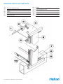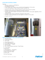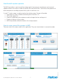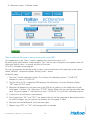
1
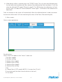
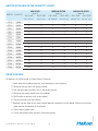
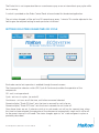
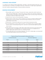
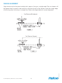
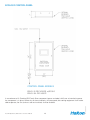
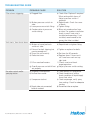
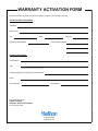
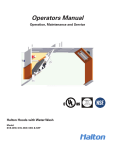
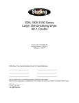
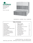
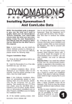
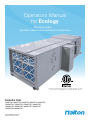
Operators Manual
for Ecology
Manual provides
Operation, Maintenance and Service Instructions
UL 1978 “Standard for Grease Ducts”, UL 710, “Exhaust Hoods for
Commercial Cooking Equipment”, ULC-S647-05 and/or UL197
EcoloAir Unit
3000CFM, 4000CFM, 5000CFM, 6000CFM, 8000CFM,
10000CFM, 12000CFM, 15000CFM, 18000CFM,
20000CFM, 24000CFM, 28000CFM, 32000CFM,
36000CFM, 40000CFM
Form#: OM020_ECOLOGY
Date: 22-06-2015 - Rev2
GENERAL
The EcoloAir System should be installed, operated and maintained as illustrated in the Installation
Instruction Manual, and the Operation and Maintenance Instruction.
1
EcoloAir Operation, Maintenance & Service Manual
2
OM-020/062015/rev2/EN
2
MAJOR COMPONENTS FOR ECOLOAIR
1. EcoloAir Control Panel 2. Filter Module 3. Exhaust Fan Module
4. Odor Reducing Module
3
EcoloAir Operation, Maintenance & Service Manual
3
OM-020/062015/rev2/EN
4
FILTER AND ODOR REDUCING MODULES
The filter and odor reducing modules are made up of the following:
1. A 2” (51mm) MERV 8 (Minimum Efficiency Reporting Value) 30/30 UL Class 1 disposable pleated Pre-Filter
2. A 15” (381 mm) MERV 14 (Minimum Efficiency Reporting Value) Hi-Flo 95 Class 1 disposable Pocket Filter.
3. A 12” (305 mm) MERV 16 (Minimum Efficiency Reporting Value) Micretain UL Class 1 Smoke Filter
4. Odor Reducing Module
5. Fire Damper
FILTER AND ODOR REDUCING MODULE PARTS
1
Hinged Access Door (Pre Filter & Medium Filter)
2
3
4
5
6
7
8
9
10
Pre Filter
11
12
13
14
15
16
17
18
19
20
Medium Filter
Hinged Access Door (Absolute Filter)
High Efficiency Filter
Ecolo Odor Reducing Module
Screwed On Access Panel
Door Latch
Ecolo Support Bracket
Fire Damper
Insulation
Hanger or Lifting Bracket
20 Gauge Insulation Skin
16 Gauge Welded Fire Proof Panels
Stiffner Channels
Removable Pressure Tube Cover
Pressure Tube Ports
Absolute Filter Track
Medium Filter Track
Pre Filter Track
FILTER AND ODOR REDUCING
MODULE PARTS VIEW
EcoloAir Operation, Maintenance & Service Manual
4
OM-020/062015/rev2/EN
Not to scale for reference only.
PRESSURE SWITCH AIR TUBE PARTS
Pressure Switch Air Tube
2
3
4
5
Pressure Switch Air Tube Connecting Nut
6
7
8
9
10
Elbow
16 Gauge Top Panel
Elbow Lock Nut
EcoloAir Operation, Maintenance & Service Manual
5
Mullion
16 Gauge Bottom Panel
Structural Base
Fire Proof Door Gasket
Filter By-Pass Gasket
OM-020/062015/rev2/EN
1
ECOLOAIR CONTROL PANEL
Features:
• Service connection to 120/1/60 Hz.
• Microprocessor based.
• User friendly touch screen for easy monitoring of parameters in the system.
• One control panel per system controls exhaust and MUA fan.
• Remote system status monitoring (Internet remote connection as an option).
• Setting of the hood airflows (calibration) through touch panel.
• Monitors each filter condition and maintains constant airflow in the system regardless of the
filter condition.
• Setting of odor control unit operation through the touch panel.
• Monitors system and displays text messages for all alarms in the system.
• Size 15’’ x 24’’ x 7’’.
1. Enclosure Panel
2. Control Transformer
3. (Not Used)
4. Power Supply 24 VDC
5. Fuse Holder (Midget Type)
6. Terminal Block ---- Ground
7. PLC Controller
8. HMI (Human Machine Interface) - Touch Screen
9. Control Relay
10.Wire Duct
11.Terminal Block ---- Distribution
12.Fuse Holder (Glass Type)
13.HMI Connection Cable
14.Glass Fuse
15.Fuse (Time Delay)
EcoloAir Operation, Maintenance & Service Manual
6
OM-020/062015/rev2/EN
Main components of the control panel are:
How EcoloAir system operates
The MC8 controller is used to read the analog signals from pressure transducers and to control
speed of exhaust fan motor in order to maintain the constant airflow. It also drives the operation of
ecolo compressor according to preset duty cycle or continuous run.
A small 7‘‘ touch screen is used to monitor the whole system. Screen will provide:
• Information on filters condition (remaining life of the filter (%)
• VFD actual speed (%)
• Features to operate ecolo compressor and to change the time settings on it
• Displays all alarms of the system
• HMI also provides calibration features for startup purpose
How to move around the screens in HMI
EcoloAir Operation, Maintenance & Service Manual
7
OM-020/062015/rev2/EN
There are total of 6 screens used for this application. They are shown below in consecutive order.
Moving between screens function is available through the labeled screen buttons at the top of each
screen. Press the ‘‘Fast Select’’ button at the lower left corner of the screen to display a pop up menu
of screen options. Press the ‘‘Fast Select’’ button again to remove the pop up menu.
The operator can go directly to the alarms screen in order to verify what alarm has occurred.
Touch screen operation
The size of the touch screen by default is 7‘‘.
Screens explanation:
The screen displays the value of the VFD speed of the exhaust fan, particular filters life remaining
(status) and alarms warning symbol. An off/on button to start/stop the operation of the system is also
displayed.
EcoloAir Operation, Maintenance & Service Manual
8
OM-020/062015/rev2/EN
1. Main screen - Filter screen
The first bar graph relates to the VFD speed.
The second bar graph relates to the DP (static pressure in inches of water column) for the pre filter.
The third bar graph relates to the DP for the medium filter.
The fourth bar graph corresponds to the DP for the absolute filter.
(The filter bar graph display shows percentage of life remaining in each filter. See the
Start Up Operating Instructions section for the specific static pressure range for each filter.)
Regular operation – Screen shows the current value of VFD speed.
All filters are at 100 % life remaining when new filters are installed, filters are all 100% clean, VFD
calibrated speed at certain percentage % (this relates to certain static pressure [“ WC] at main DP)
when filters are clean and last there are no alarms in the system.
Ecolo odor control unit operation is enabled through the ecolo screen.
The three position selector switch (Off/ Cycle & Continuous) enables the operation of the
compressor.
Off - unit is not operational.
Cycle - unit runs in cycles (on and off).
Continuous - unit runs on all the time, until other command selected.
Numeric display ‘‘Ecolo ON time’’ sets the time in seconds for unit to be on.
Numeric display ‘‘Ecolo OFF time’’ sets the time in seconds for unit to be off.
Once these times are set, if selector switch is in cycle mode, unit will run for a preset time, when
this time has been elapsed, the operation of the compressor automatically stops and it will be off
for the preset time set in off mode. The status changes again to ‘‘on’’ state and goes in cycles as
previously described.
EcoloAir Operation, Maintenance & Service Manual
9
OM-020/062015/rev2/EN
2. Ecolo screen --- ecolo odor control screen
3. Calibration screen - Calibrate screen
How to calibrate the system during start up by using HMI
First appearance is the ‘‘filters’’ screen ---appears first when the system is off.
By pressing the off/on button, screen displays ‘‘ON’’, the fan starts and goes to the speed which will
maintain a default value --- a manual set point of the main
DP of 0.5‘‘ (variable) set by program.
For start up purposes and setting up the system, a service technician will need to go to the screen
called ‘‘calibrate’’. Calibration requires Security Level 1 access.
Calibration steps:
1. Press the ’’Initiate calibration’’ button. This initiates the calibration process. ’’CALIB OFF’’
changes its state to ‘‘CALIB ON’’.
2. The fan will go to 70% speed and HMI displays that calibration is active (calibration display
‘‘OFF’’ goes to ‘‘ON’’ state).
3. Measure the differential static pressure on the TAB port or velocity on the hood filters for old
style hoods. If airflow is Ok, then press ‘‘STORE’’ button. Make sure you see the new calibrated
value ‘‘Store fan speed %‘‘ and then press once ‘‘CALIB ON’’. This will finish calibration process.
4. In case of an unsatisfactory measurement:
5. Press jog buttons ‘‘INC’’ and ‘‘DEC’’, the speed of the fan will be increased or decreased to allow
for airflow changes. You can monitor the speed in the Fan speed % block.
7. Repeat using ‘‘DEC’’ or ‘‘INC’’ until design airflow is reached.
EcoloAir Operation, Maintenance & Service Manual
10
OM-020/062015/rev2/EN
6. Measure the hood differential static pressure again.
8. When design airflow is reached, press the ‘‘STORE‘‘ button. This will store the calibrated values
for main pressure transducer, pre filter, medium filter and absolute filter transducers. It will also
store the calibrated VFD speed (‘‘Store fan speed’’). The HMI displays that calibration is off and
the last step is to undo the ‘‘initiate calibration’’ button again --- confirmation that calibration has
been done.
From this moment on the system will automatically follow the calibrated values in order to maintain
the constant airflow and it will start monitoring the status of the filters (filter remaining life).
4. Alarm screen
Possible alarms
Alarms which can appear on the ‘‘alarms’’ screen are:
1. Pre-filter clogged
2. Pre-filter missing
3. Medium filter clogged
4. Medium filter missing
5. Absolute filter clogged
6. Absolute filter missing
7. Fire
8. Change filters (if VFD speed is @100 % for more than 10 min!)
9. Low ecolo level (low level of ecolo solution in the tank)
10. Fan failed!
EcoloAir Operation, Maintenance & Service Manual
11
OM-020/062015/rev2/EN
Alarms screen appearance:
5. User Guide screen
This screen gives a pictorial reference to the main screen. It offers a guide to the features and use of
the touch screen and can help navigate the HMI screens. Refer to it when you need help interpreting
the information and features of the Main Screen.
This screen will be used by your service agent only.
EcoloAir Operation, Maintenance & Service Manual
12
OM-020/062015/rev2/EN
6. Security screen
FILTER REPLACEMENT
Note: Halton filters should be used to avoid the need to re-calibrate.
To replace filters, proceed as follows:
1. Shut off fan.
2. Loosen the access door latches and open door.
3. Check how filters are set in place to prevent air by-pass.
4. Remove filter clamp on absolute filters with hook handle provided in unit, located on inside of
access door.
5. Remove all filters by sliding out the filter along bottom of filter track.
6. Slide the new filters along the bottom filter track and seat properly along filter by-pass gasket.
Replace all filters in this manner. Ensure all filters are seated properly and replace filter clamp to
lock Absolute filters in place.
7. Check that pressure transducer air tube connection have not been disturbed by removing
pressure tube chase.
8. Close access door and lock all latches.
9. To start fan, turn on disconnect switch at fan.
10.If the fan stops, remove the filter access door and check if all filters have been replaced and are
seated properly.
11.Should fan continue to shut off, check all pressure transducer settings.
FILTER REMOVAL TEST
To perform Filter Removal Test, proceed as follows:
1. Ensure all filters are in place and properly seated.
2. Remove one absolute filter.
3. Start fan. Alarm should sound and fan should shut down within one minute.
4. Replace High Efficiency filter.
5. Restart Fan.
NOTE: A FACTORY INSTALLED FIRESTAT SET AT 350˚F (177˚C) IS LOCATED AT THE ENTRANCE
TO THE EXHAUST FAN. IT WILL SHUT OFF THE EXHAUST AND SUPPLY FANS IF THE SET
TEMPERATURE IS REACHED.
FIRE DAMPER
1. Loosen the access door latches.
2. Remove defective fusible link and replace with new link, by holding up damper blades and
wrapping link support across blades and secure at clip, on other side of frame.
3. Close the access door and lock all latches.
4. Start Fan.
EcoloAir Operation, Maintenance & Service Manual
13
OM-020/062015/rev2/EN
The Fire Damper is located at the discharge set of the EcoloAir Filter Module. All Fire Dampers are
supplied with fusible links set to close at 286˚F (138˚C) or 165˚F U.S. Only. Should the fusible link
melt and blades shut down by gravity, linkage replacement is necessary as follows:
HALTON ECOLOAIR FILTER QUANTITY CHART
MODEL CAPACITY
PRE FILTER
MEDIUM FILTER
ABSOLUTE FILTER
MERV 8
MERV 14
MERV 16
FULL SIZE
HALF SIZE
FULL SIZE
HALF SIZE
24”x 24”x 2”
24”x12”x2”
24”X24x15”
24”x12”x15”
FULL SIZE
HALF SIZE
24”x24”x12” 24”x12”x12”
EF3
3000
1
1
1
1
1
1
EF4
4000
2
0
2
0
2
0
EF5
5000
2
1
2
1
2
1
EF6
6000
2
2
2
2
2
2
EF8
8000
4
0
4
0
4
0
EF10
10000
4
2
4
2
4
2
EF12
12000
6
0
6
0
6
0
EF15
15000
6
3
6
3
6
3
EF18
18000
9
0
9
0
9
0
EF20
20000
9
3
9
3
9
3
EF24
24000
12
0
12
0
12
0
EF28
28000
12
4
12
4
12
4
EF32
32000
16
0
16
0
16
0
EF36
36000
16
4
16
4
16
4
EF40
40000
20
0
20
0
20
0
ODOR CONTROL
To replace a 5 Gallon bottle of Ecolo Scentry Solution
1. Open enclosure cabinet door by unscrewing the two lock bolts.
2. Remove the cap from the empty bottle.
3. Pull the dip tube assembly out of the empty bottle.
4. Remove the empty bottle from the cabinet.
5. Refill bottle or replace with a new bottle.
6. Place the bottle into the cabinet.
7. Replace the dip tube or low level control device assembly into the bottle. Make sure the dip
tube reaches the bottom of the bottle.
8. Place cap on bottle neck.
9. Close the cabinet door and lock with locking bolts.
EcoloAir Operation, Maintenance & Service Manual
14
OM-020/062015/rev2/EN
The Ecolo Unit is set to operate either on a continuous spray or on an intermittent spray cycle while
fan is running.
A switch is provided on the Ecolo Control Panel to be activated for the desired application.
The unit when shipped, will be set for a 20 second spray every 1 minute. This can be adjusted in the
field to give the required setting for each particular installation.
SETTING ECOLO TIME ON AND TIME OFF CYCLE
Ecolo odor control unit operation is enabled through the ecolo screen.
The three position selector switch (Off/ Cycle & Continuous) enables the operation of the
compressor.
Off - unit is not operational.
Cycle - unit runs in cycles, (on and off).
Continuous - unit runs on all the time, until other command selected.
Numeric display ‘‘Ecolo ON time’’ sets the time in seconds for unit to be on.
Numeric display ‘‘Ecolo OFF time’’ sets the time in seconds for unit to be off.
EcoloAir Operation, Maintenance & Service Manual
15
OM-020/062015/rev2/EN
Once these times are set, if selector switch is in cycle mode, unit will run for a preset time, when
this time has been elapsed, the operation of the compressor automatically stops and it will be off
for the preset time set in off mode. The status changes again to ‘‘on’’ state and goes in cycles as
previously described.
EXHAUST FAN MODULE
1
Access Door
2
3
4
5
6
7
8
9
10
11
12
13
Side Panel
14
15
16
17
18
19
20
21
22
23
24
25
Corner Panel
Disconnect Switch
Hanger or Lifting Brackets
Spring Isolators
Floating Steel Base
Motor Slide Base
Structural Base
Bottom Panel
Lower Fan Discharge Panel
Flexible Connection
Fan
Fan Pulley
Fan Belt
Motor
Motor Pulley
Electrical Box Terminal Strip
Pressure Switch (optional location)
Firestat
Air Tubes for Pressure Switch (optional location)
Pressure Switch Box Cover (optional location)
Pressure Tube Cover (optional location)
Top Panel
Upper Fan Discharge Panel
FAN TYPES
NOTE: Ensure motor disconnect switch in exhaust fan housing is in OFF position prior to any service
work.
EcoloAir Operation, Maintenance & Service Manual
16
OM-020/062015/rev2/EN
For all models, a double width double inlet Class 2 airfoil type fan is used. The motor and drive package is located in the exhaust airstream. All fan wheels are mounted to facilitate easy removal should
adjustment or repairs be necessary.
FAN WHEEL REPLACEMENT
It is unlikely the fan wheel will require replacement. However, if the wheel requires balancing, it can
normally be done in the field by a certified fan technician. Should the fan wheel require replacement,
the work should only be performed by a Halton certified fan technician.
BEARING REPLACEMENT
1. Remove belts and the fan sheave. To remove fan sheave, remove the cap bolts and screw
them into the threaded holes in the bushing. Snug up all bolts then continue to tighten each
cap bolt in half turn increments until the sheave comes loose from the bushing. The bushing
and sheave should now slide off the fan shaft.
2. Loosen the set screws on the locking collars of bearing.
3. Remove the fan wheel and fan shaft by sliding the fan shaft out through the bearing collars.
Polishing the fan shaft with emery cloth and some light lubrication on the fan shaft will
make removal much easier.
4. Remove bolts, fastening the bearing to the top and bottom bearing base plates.
5. Re-install equipment in reverse order of removal. Care should be taken to properly tighten
the set screws in the bearing locking collar’ see chart for recommended tightening torque
of set screws.
6. When replacing the fan sheaves, slide sheave and bushing onto the fan shaft and insert the
cap bolts into the non-threaded holes of the bushing and screw into threaded holes in sheave. Tighten each cap bolt a half turn in rotation until tight.
7. Ensure proper belt tension and sheave alignment. The use of straight edge is recommended
to ensure proper alignment and maximum efficiency.
Tightening Torque Recommended for Bearing Set Screws
Set Screw Tightening
Inches
mm
(in.lb.)
(kgm.)
1
25
30
0.04
1 - 3/16
30
40
0.05
1 - 7/16
37
50
0.06
1 - 11/16
43
65
0.08
1 - 15/16
49
65
0.08
2 - 3/16
56
80
0.10
2 - 7/16
62
135
0.16
EcoloAir Operation, Maintenance & Service Manual
17
OM-020/062015/rev2/EN
Fan Shaft Diameter
SHEAVE ALIGNMENT
Align the drive by the four-point method with a piece of string or a straight edge. The two sheaves will
be aligned when two points (near and far) on the face of each of the sheaves touch the straight edge
of the string when the string is a straight line. Refer to the figure below for correct alignment.
Fan Sheaves Misaligned
EcoloAir Operation, Maintenance & Service Manual
18
OM-020/062015/rev2/EN
Fan Sheaves Aligned
BELT ADJUSTMENT
Measure the belt span, (see image). Using a spring
scale, apply a perpendicular force to any one of the
belts at the mid point of the span. Measure the force
required to deflect any one of the belts 1/64” (.40mm)
for every inch (25mm) of span length. For example,
the deflection for a 32” (813mm) span would be 1/64”
(.40mm) multiplied by 32, or 1/2” (13mm). The force
required to deflect the belt is listed in the table below.
Initially, tighten the belts to the values listed in column
“Run-In Time”. There will normally be a drop in tension
during the first 24 to 49 hours of operation. During this
“run in” period, the belts seat themselves in the sheave
grooves and the initial stretch is removed. After a day
or two, the drive should be stopped and another check
made for the correct amount of tension. The tension
should now compare with the values in column “Normal
Time”. If the force is below the level in column “Normal
Time”. The belts are too loose. If the force is greater than
the high level, the belts are too tight. Readjust so that
the deflection force is between the high and low value in
column “Normal Time”.
CONVENTIONAL BELT DEFLECTION FORCE
A
B
SMALL DIAMETER RANGE
Inches
3.0 - 3.6
3.8 - 4.8
5.0 - 7.0
3.4 - 4.2
4.4 - 5.6
5.8 - 8.6
mm
76 - 91
97 - 122
127 - 178
86 - 107
112 - 142
147 - 218
EcoloAir Operation, Maintenance & Service Manual
PRIME MOVER BELTS
RUN-IN TIME
NORMAL TIME
lbs.
kg.
lbs.
kg.
4-1/2
9.9
3
6.6
5-1/4
11.6
3-1/2
7.7
6-1/2
14.3
4-1/4
9.4
6-1/2
14.3
4-1/4
9.4
8-1/4
18.2
5-1/2
12.1
10-1/2
23.1
7
15.4
19
OM-020/062015/rev2/EN
BELT
ECOLOGY CONTROL PANEL
CONTROL PANEL MODELS
EPLV5 - 3: DRY HOODS, w/ECOLO
EPLV5 - 3A: DRY HOOD
EcoloAir Operation, Maintenance & Service Manual
20
OM-020/062015/rev2/EN
In accordance to UL Standard S647, each filter component (grease and odor) shall have an interlock to prove
the component is in place. Where any of these interlocks are interrupted, the cooking equipment shall not be
able to operate, the fans (exhaust and re-circulation) shall be disabled.
TROUBLESHOOTING GUIDE
PROBLEM
PROBABLE CAUSE
SOLUTION
Unit not exhausting properly
a) Belts slipping or broken.
b) Fire damper shut. Check
ecology unit and exhaust
hood.
c) Plugged filter.
d) Water level in exhaust hood
too high. Drain plugged.
e) Exhaust fan motor off on
overload.
f) Duct work or air outlet
blocked.
a) Loose damper linkage causing
both dampers to close.
b) Loose or broken fan belts.
c) Plugged air filter.
d) Supply fan motor off on
overload.
e) Separate supply air system not
operating.
a) No power.
b) Fuses blown.
a) Tighten or replace belts.
b) Replace fusible link or holding
wire. Check cause.
No make-up air
Unit will not start
c) Off on overload heater in
magnetic starter.
d) 120 volt control transformer
fuse.
e) Blown 5 amp. fuse in exhaust
hood wash control panel.
f) Defective exhaust fan motor.
c) Replace filter.
d) Unplug drain, check filter if wet.
e) Reset and check amperage
draw
f) Remove obstruction.
a) Tighten and reset linkage
b) Tighten or replace belts.
c) Replace filters.
d) Reset and check amperage
draw.
e) Recommend to owner to have
system serviced.
a) Check power supply.
b) Replace fuse, check for cause
of blown fuse.
c) Reset overload and take
amerage reading to be sure
motor is not overloaded. A
blown fuse can cause an overload to trip.
d) Replace fuse; if blown, check
for cause in 120 volt circuit incl.
exhaust hood wash control
panel.
e) Replace fuse. Check for cause
in detergent pump or solenoid
coils.
f) Replace motor. Check for cause
bearings, alignment, motor
burn out. Check overload settings with name plate.
g) Turn to “ON” position.
EcoloAir Operation, Maintenance & Service Manual
21
OM-020/062015/rev2/EN
g) Fan switch on Ecology control
panel in “OFF” position.
h) Control switch on exhaust
h) Turn to “RUN” position
hood panel in “WASH” position
TROUBLESHOTING GUIDE
PROBLEM
PROBABLE CAUSE
SOLUTION
Filter alarms triggering
a) Plugged filter.
a) Check filter. Replace if required
What setting did it alarm at?
Adjust pressure switch if
required.
b) Repair break. Check for cause
of break.
c) Tighten fitting.
d) Blow out condensation from
air tube. For outdoor installation
check to see if heat wire is
installed and operating. If not
installed, recommend to the
owner that it be installed.
a) Seat filters.
b) Repair break or tighten fitting.
b) Broken pressure switch air
tube.
c) Loose pressure switch fitting.
d) Condensation in pressure
switch tubing.
Unit starts, then shuts down a) Filter not seated properly
b) Broken or loose pressure
switch air tube.
c) Exhaust fan belt slipping (not
moving enough air).
d) Timer not set correctly.
e) Defective timer.
d) Set time for 60 seconds.
e) Replace timer. If burnt out it
will have burn mark on top
right side.
f) Check, reset and check
f) Off on overload heaters.
amperage draw.
g) Overall pressure switch #4 not g) Adjust pressure switch setting.
set properly.
a) No power to compressor
a) Check power to Compressor.
b) No fluid from nozzle.
b) Check condition of orifice,
check condition of liquid supply
line at foot valve.
c) Compressor too hot.
c) Check amperage, verify spray
time setting. Check for adequate
venting.
d) Supply tube not connected/
d) Re-connect tube or replace.
loose or cracked.
EcoloAir Operation, Maintenance & Service Manual
22
OM-020/062015/rev2/EN
No odor control and/or
spraying action
c) Tighten or replace fan belts.
START UP OPERATING INSTRUCTIONS
IMPORTANT: Initial system start-up and certification by factory authorized personnel only.
Operating system prior to certification will void warranty.
• Turn on main disconnect switch at EcoloAir fan.
• The EcoloAir filter unit is designed to operate with the following pressure drops across each filter
stage.
1) Pre Filter .2” to .75”
2) Medium Efficiency Filter .4” to 1.25”
3) High Efficiency Filter
.75” to 2.0”
When the pressure drop for each filter bank exceeds the upper limits, an audible/visual alarm will
sound and activate a pilot light.
The alarm is a warning only, and does not shut the system down. The alarm can be silenced by
pushing the alarm reset button in the centre of the Ecology panel.
The firestat is also capable of triggering an alarm on the control panel. Upon the firestat detecting 350°F,
it will shut the exhaust fan off and display a FIRE alarm. Once the firestat sees the temperature drop
down below 320°F it will clear the alarm on the panel and restore operation of the exhaust fan. • There are two other alarm conditions:
1) “A filter not in place” sensing system. 2) A fire state to sense excessive temperatures in the
duct. Should either alarm be triggered, the audible/visual alarm will sound, an indicator light
labeled “filters overall” will be illuminated, and the system will shut down. After the cause
of the alarm has been corrected, the system can be restarted by pushing the reset button
and also turning the main disconnect switch to the “OFF” position. then back to the “ON”
position.
MAINTENANCE INSTRUCTIONS
NOTE: Heavy hamburger type operations require extra maintenance and frequent filter changes. We
recommend a maintenance contract be set up for this type of operation.
MONTHLY:
• Check condition of air filters. Replace if necessary.
• Check odor control liquid level. Replace if necessary.
• Check odor nozzle condition (check for debris)
When replacing belts when multiple belts are used, they MUST ALL BE REPLACED, as they are a
matched set.
EcoloAir Operation, Maintenance & Service Manual
23
OM-020/062015/rev2/EN
QUARTERLY: (to be performed by a qualified service agent).
• Check belt tension at exhaust fan. Tighten as required.
• Check belt alignment.
• Lubricate motor bearings.
• Lubricate fan bearings.
• Check contacts on motor starter in control panel.
• Check amperage draw of fan motor.
• Check to see if the overall filter warning system operates correctly. This can be done by removing
the high efficiency filters and starting the system.
• Check fusible link on the fire dampers (filter section)
ROUTINE MAINTENANCE
1. A preventive maintenance program is an important aspect of an effective safety program.
Consult the manufacturing or other qualified service agents with question concerning changes
observed during periodic inspections and routine maintenance.
2. The fan manufacturer’s operating and maintenance recommendations, as well as the
components manufacturer’s instructions (such as motor, bearing, drives, etc.) should be strictly
followed.
3. Maintenance should always be performed by experienced and trained personnel who are aware of the hazards associated with rotating equipment. Do not attempt any maintenance
on a fan unless the fan power supply has been locked out and tagged out and the impeller has
been secured.
4. When performing maintenance functions which include disassembly of the fan, careful
consideration should be given to the size, weight center of gravity, and lifting means of the
fan components. It should also be noted that the outboard bearing on some fans such as
arrangements 1,8,9 and 10 is often cap-loaded. Removal of the securing means may result in a
sudden change in impeller position.
5. Historical data is often the best indicator for determining the operational condition of the
fan. Maintenance logs which include lubrication, vibration levels, temperature levels, power
requirements, inspection, and other pertinent records should be maintained and consulted as
necessary when assessing the condition of the fan.
6. Under normal circumstances, handling clean air, the system should require cleaning only once a
year. However, the fan and system should be checked at regular intervals to detect any unusual
accumulation.
7. The fan impeller should be specially checked for build-up of material or dirt which may cause
an imbalance with resulting undue wear on bearings and belt drives. A regular maintenance
program should be established as needed to prevent material build-up.
EcoloAir Operation, Maintenance & Service Manual
24
OM-020/062015/rev2/EN
8. Periodic inspection of the rotating assembly should be made to detect any indication of
weakening of the rotor because of corrosion, erosion, or metal fatigue. Where signs of
deterioration are found, lock out and tag out the impeller until the unit had been inspected and
approved by a qualified consultant.
START UP CHECK LIST
1.1 Before putting any fan into initial operation, the manufacturer’s instructions should be followed.
Transportation, handling, and installation can cause fasteners to loosen, and cause misalignment
of fan components. Carefully follow this check list when commissioning equipment.
1.2 Lock out the primary and all secondary power sources.
1.3 A complete inspection should be made of all the ductwork and the interior of the fan. Make
certain there is no foreign material which can be drawn into or blown through the fan or ductwork
Appropriate protective measures and safety practices should be observed when entering or
working within these areas. These measures might include the use of goggles, respirators, or
other personal protective devices.
1.4 Make sure the foundation or mounting arrangement and the duct connections are adequately
designed and installed per drawings and in accordance with recognized acceptable engineering
practices and with the fan manufacturer’s recommendations.
1.5 Check and tighten all bolts, fasteners, and set screws as necessary .
1.6 Check the fan assembly and bearings for proper grounding to prevent static electricity discharge.
1.7 Ensure power and drive components such as motor starter, variable frequency drive, or hydraulic
power unit are properly sized, matched , and connected to the fan.
1.8 Check bearing for recommended lubricant and lubrication amount.
1.9 Spin the rotation assembly to determine whether it rotates freely, without hitting anything, and is
not grossly out of balance.
1.10 Inspect impeller for proper rotation for the fan design.
1.11 Check alignment of drives and all other components.
1.12 Check the belt drive for proper sheave selection and installation and make sure the sheaves are
not reversed (excessive speeds could develop).
1.13 Check for recommended belt tension.
1.14 Properly secure all safety guards.
1.15 Assure that all appropriate warnings have been put in place.
EcoloAir Operation, Maintenance & Service Manual
25
OM-020/062015/rev2/EN
1.16 Secure all access doors to the fan and ductwork.
START UP CHECK LIST Continued...
1.17 Momentarily energize the fan to check the direction of rotation. Listen as the fan coasts to a
stop for any unusual noise, identify the source, and take corrective action as necessary.
1.18 Switch on the electrical supply and allow the fan to reach full speed. Check carefully for:
a) Excessive vibration
b) Unusual noise
c) Proper belt alignment
d) Proper lubrication
e) Proper amperage, voltage, or power values.
f) If any problem is indicated, SWITCH OFF IMMEDIATELY.
g) Lock out the power supply. Secure the fan impeller if there is a potential for wind milling.
Check carefully for the cause of the trouble, correct as necessary, and repeat check list
procedure.
2.0 Even if the fan appears to be operating satisfactorily, shut down after a brief period, lock out the
power supply, and recheck item 1.5 through 1.17 as the initial start-up may have loosened the
bolts, fasteners, and set screws.
3.0 The fan may now be put into operation, but during the first eight (8) hours of running, it should be
closely observed and checked for excessive vibration and noise. At this time checks should also
be made of motor input current and motor and bearing temperatures to ensure that they do not
exceed manufacturer’s recommendations.
4.0 After eight (8) hours of operation, the fan should be shut down and the power locked out. Check
list items 1.5 through 1.17 should be inspected and adjusted, if necessary.
5.0 After twenty-four (24) hours of satisfactory operation, the fan should be shut down (locked out)
and the drive belt tension should be readjusted to recommended tension.
6.0 After commissioning and start-up, the fan should be operated and maintained in accordance with
the manufacturer’s and component manufacturer’s recommendations.
EcoloAir Operation, Maintenance & Service Manual
26
OM-020/062015/rev2/EN
For any questions, please call Halton Service Network at US (270) 237-5600 or Canada (905) 624-301.
WARRANTY ACTIVATION FORM
This form must be completed and returned to Halton in order for your warranty to be valid.
Job & Location Information:
Job Name:
Street Name:
City:
State:
Zip Code:
Equipment Start-Up Date:
Product Serial Numbers:
Contact Information:
Contact Name:
Title:
Chef, Kitchen Mgr/Facilitly Mgr/Property Mgr/ etc.
Facility Management Company Name (if applicable):
Email:
Phone Number:
Cell Number:
Submit by Email
Please use the "Submit by Email" button to submit this form electronically or:
Fax completed form to:
Halton Company
Attention: Service Department
1-800-442-5866
www.halton.com
OM-020/062015/rev2/EN
Fax: (270) 237-5700
HALTON LIMITED WARRANTY
Halton (“Manufacturer”). Warrants only to its direct purchasers and to no others, that all products
manufactured by the Manufacturer shall be free from defect in materials and workmanship for a period
of twelve (12) months from the date of the original installation and start-up or eighteen (18) months
from date of shipment, whichever occurs first. All products sold but not manufactured by Manufacturer
will be warranted for a period of twelve (12) months from date of shipment. (Halton’s Warranty Card
must be completely filled out and returned to Halton within 3 weeks after the equipment start-up
date for your warranty to be valid *IMPORTANT NOTE: “IF” this form is returned within the specified
timeframe, Halton will extend your standard warranty by 120 days.)
For products manufactured by the Manufacturer we agree to pay any reasonable labor costs necessary
to repair or replace, at Manufacturers option, defective parts or materials for a period of twelve (12)
months from date of original installation and start-up or eighteen (18) months from date of shipment,
whichever occurs first. All labor costs subject hereto shall be performed during standard work hours at
straight-time rates. For products sold but not manufactured by the Manufacturer we agree to pay any reasonable labor costs
necessary to repair or replace, at Manufacturers option, defective parts or materials for a period of (90)
days from date of original installation and start-up or (12) months from date of shipment, whichever
occurs first. All labor costs subject hereto shall be performed during standard work hours at straighttime rates.
Purchaser shall pay incurred premium labor charge, including overtime, weekends and holidays.
Travel time, service charges, miscellaneous tools, material charges, and labor charges resulting from
inaccessibility of equipment will not be paid by Manufacturer.
This LIMITED WARRANTY SHALL APPLY ONLY to products that have been installed and maintained
in accordance with the installation and Care Instruction Manuals. Purchaser shall be solely responsible
for adhering to the instructions and procedures set forth in the said instruction manuals.
This LIMITED WARRANTY SHALL NOT BE APPLICABLE to any damage or defect resulting from fire,
flood, freezing or any Act of God, abuse, misuse, accident, neglect or failure to adhere to all instructions
set forth in the installation and Care Instruction Manuals. Furthermore, this limited warranty shall not
apply to any product that has been altered, unless such alteration has been approved in writing by a
duly authorized representative of the manufacturer. In no event shall the manufacturer be liable for any
loss, expense, personal injury or consequential damage, of any kind or character, as may result from a
defect in material, and/or workmanship, however caused.
Continuous product improvement is a Halton policy, therefore specifications and design are subject to change without notice.
Halton Company
101 Industrial Drive, Scottsville, KY 42164, USA
Phone 270 237 5600 Fax 270 237 5700
Website: www.halton.com
Halton Indoor Climate Systems, Ltd.
1021 Brevik Place, Mississauga, ON L4W 3R7, Canada
Phone 905 624 0301 Fax 905 624 0301
OM-020/062015/rev2/EN
EXCEPT AS IS EXPRESSLY SET FORTH IN THIS LIMITED WARRANTY, MANUFACTURER MAKES
NO WARRANTY OF MARKETABILITY FOR FITNESS OR ANY PARTICULAR PURPOSE. NEITHER
DOES MANUFACTURER MAKE ANY WARRANTY, EXPRESSED OR IMPLIED, WITH RESPECT TO
PRODUCTS SOLD BY MANUFACTURER OR AS TO THE USE THEREOF.