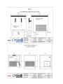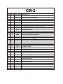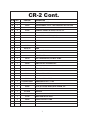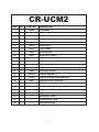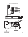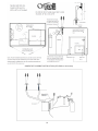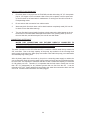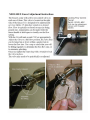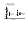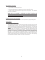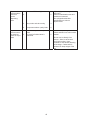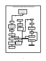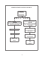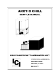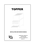
1
CR-2 Countertop
& CR-UCM2 Undercounter
Installation & Service Manual
6313
IMPORTANT:
This manual is a guide for installing, operating,
servicing and maintaining this equipment.
Refer to Table of Contents
for page location of detailed information to answer questions that
arise during installation, operating, service and maintenance, or
installation of this equipment.
TABLE OF CONTENTS
PAGE
PREFACE ........................................................................................................................... 1
CHAPTER I GENERAL DESCRIPTION ............................................................................. 2
SYSTEM DESCRIPTION ....................................................................................... 2
DESIGN DATA ....................................................................................................... 3
MODEL LINE DRAWINGS………………………………………………………………4
CR-2 EXPLODED VIEW ........................................................................................ 5
DESCRIPTION, EXPLODED VIEW, CR-2 ............................................................ 6
CR-UCM2 EXPLODED VIEW ................................................................................ 8
DESCRIPTION, EXPLODED VIEW, CR-UCM2 .................................................... 9
COMMON PARTS LIST………………………………………………………………..11
ELECTRICAL SCHEMATIC, DUAL CARB, DIRECT WIRE ................................ 12
ELECTRICAL SCHEMATIC, S-68-B ................................................................... 12
THEORY OF OPERATION .................................................................................. 14
CHAPTER II INSTALLATION ........................................................................................... 17
UNPACKING AND INSPECTION ........................................................................ 17
SELECTING LOCATION ..................................................................................... 17
LOCATION RECOMMENDATIONS AND HINTS ................................................ 18
SAMPLE INSTALL DRAWING………………………………………………………...18
CR-UCM2 INSTALLATION .................................................................................. 20
CR-UCM2 INSTALL DIAGRAM……………………………………………………….21
CR-2 INSTALLATION…………………………………………………………………..22
CR-2 INSTALL DIAGRAM……………………………………………………………..23
INSTALL HIGH PRESSURE CO2 REGULATOR, CO2 CYLINDER
AND LINES .......................................................................................................... 24
INSTALL WATER FILTER ASSEMBLY............................................................... 25
INSTALL WATER PRESSURE REGULATOR, (OPTIONAL) ............................. 25
INSTALL DRAIN LINE ......................................................................................... 26
CONNECTING WATER INLET ............................................................................ 26
CONNECTING CBR-V2C DRAFT TOWER…………………………………………27
ELECTRICAL REQUIREMENTS ......................................................................... 28
CHAPTER III PREPARATION .......................................................................................... 29
PREPARING SYSTEM FOR OPERATION ......................................................... 29
PREPARING AND STARTING REFRIGERATION UNIT .................................... 29
ACTIVATE HIGH PRESSURE CO2 SYSTEM .................................................... 29
ADJUST WATER FLOW RATE ........................................................................... 29
CHAPTER IV OPERATORS INSTRUCTIONS ................................................................. 30
DAILY PRE-OPERATION CHECK ...................................................................... 30
REPLENISHING CO2 SUPPLY ........................................................................... 30
COOLING UNIT MAINTENANCE ........................................................................ 30
CHECKING WATER BATH.................................................................................. 30
CHANGING WATER BATH ................................................................................. 31
ADJUSTMENTS ................................................................................................... 31
ADJUSTING WATER FLOW RATE..................................................................... 31
TESTING FOR LEAKS ........................................................................................ 31
SETTING AND ADJUSTING SELF SERVE X0101-HEX FAUCET..……………..32
CHAPTER V SERVICE AND MAINTENANCE ................................................................. 33
PERIODIC INSPECTION AND CLEANING......................................................... 33
DAILY CLEANING………………………………………………………………………33
WEEKLY CLEANING…………………………………………………………………...33
MONTHLY CLEANING…………………………………………………………………33
CR-UC2 CABINET MAINTENANCE .................................................................... 34
TABLE OF CONTENTS (cont’d) ................................................................ PAGE
CR-2 CABINET MAINTENANCE……………………………………………………...34
CLEANING CONDENSER COIL ......................................................................... 34
CHECKING/CHANGING WATER BATH ............................................................. 35
WATER PUMP MAINTENANCE ......................................................................... 36
CARBONATOR MAINTENANCE ........................................................................ 37
SERVICING CHECK VALVES ............................................................................. 37
REPLENISHING CO2 SUPPLY ........................................................................... 40
CHANGING WATER FILTER CARTRIDGE ........................................................ 40
ADJUSTMENT OF CO2 REG .............................................................................. 40
SANITIZING PROCEEDURES ............................................................................ 41
CHAPTER VI TROULBESHOOTING ............................................................................... 42
CARBONATOR .................................................................................................... 42
WATER PUMP MOTOR WILL NOT OPERATE ..................................... 42
WATER PUMP MOTOR WILL NOT SHUT OFF .................................... 42
WATER PUMP WILL NOT SHUT OFF AND PRESSURE
RELIEF ENGAGED................................................................................. 42
SHORT CYCLING OF WATER PUMP MOTOR .................................... 42
WATER PUMP CAPACITY TOO LOW................................................... 42
WATER PUMP OPERATES BUT WATER PUMP DOES
NOT PUMP ............................................................................................. 42
FROZEN WATER BATH ......................................................................... 43
COOLING OR CONDENSING UNIT NOT OPERATIONAL ................... 43
AGITATOR MOTOR NOT OPERATING ................................................ 43
COMPRESSOR DOES NOT OPERATE ................................................ 43
COMPRESSOR WORKS CONTINUOUSLY BUT DOES
NOT FORM SUFFICIENT ICE BANK ..................................................... 43
COMPRESSOR WILL NOT STOP AFTER SUFFICIENT
ICE BANK IS PRODUCED ..................................................................... 44
CONDENSER FAN MOTOR NOT OPERATING ................................... 44
NO WATER BEING DISPENSED ........................................................... 44
DISPENSED PRODUCT CARBONATED TO LOW ............................... 44
DISPENSED PRODUCT MAKES FOAM AS IT LEAVES
NOZZLE .................................................................................................. 45
DISPENSED PRODUCT COMES OUT CLEAR BUT FOAMS
WHEN IT TOUCHES CUP OR GLASS .................................................. 45
CARBONATION TROUBLESHOOTING FLOW CHART #1 ............................... 46
CARBONATION TROUBLESHOOTING FLOW CHART #2 ............................... 47
CARBONATION TROUBLESHOOTING FLOW CHART #3 ............................... 48
NOTE SECTION ............................................................................................................... 49
WARRANTY BOND………………………………………………………………………………50
PREFACE
Crysalli is manufactured on behalf of Western Pacific Distributors by
International Carbonic Inc.
INTERNATIONAL CARBONIC INC. has enjoyed over 53 years of
manufacturing excellence in the field of carbonation and in the beverage
related industry. They have had a long and proud history with quality as
their standard and innovation as their goal. They enjoyed patents on the
first Sodajet type carbonator. This method of carbonation instantaneously
carbonated the water to 100% saturation.
They developed the first
patented dispensing valve to dispense bulk beverage with carbonation
equal to or in excess of bottled beverages. A valve with three flavors and
soda was another first. They were the first to incorporate the total postmix
package, i.e., carbonation, refrigeration, and the ability to dispense from
one self contained unit. They have pioneered many such firsts and will
continue to develop advanced systems for the future, such as electronic
interrogatable portion controls to electronic liquid level controls.
1
CHAPTER I
GENERAL DESCRIPTION
This chapter gives the description, theory of operation, and design data for the CR-2 and
CR-UCM2 Crysalli units and related components.
SYSTEM DESCRIPTION
The Crysalli CR-UCM2 series of Undercounter Artisan Water units are a configuration of
cold dispensed sparkling and still filtered water, requiring a draft tower to dispense the
product. These units have a water bath derived re-circulation system to help maintain
product temp between chiller and tower.
The Crysalli CR-2 series Countertop Artisan Water units are configured to dispense cold
sparkling and still filtered water directly from the taps on the unit. Left side tap is always
sparkling water, right side is always still water.
The CR-2 and CR-UCM2 units consist of a condensing unit, a manual fill water reservoir,
water-cooling coil, a carbonator tank, (carbonated systems only), an agitator/recirculation pump, and cooling coil(s). The unit will freezer over 1/3 of the reservoir/bath
water to create an ice bank. This ice bank is responsible for maintaining a 32 degree
reservoir water temp. The cooling coils and carbonator tank are submerged in the
reservoir/bath water to chill and maintain ice cold product temperatures.
For proper function the Crysalli units must have a filtered water supply, and electrical
supply and drainage. Other items that will be required are the Draft tower, water filtration
system, installation kit including a High pressure CO2 regulator or secondary pressure
regulator, connecting lines, fitting and C02 tank.
WARNING: Before shipping or relocating a Crysalli into a freezing ambient
environment empty still and carbonated water. Ice bank melted, and
water drained from water bath. A freezing ambient environment will
cause existing water in unit to freeze possibly resulting in damage to
pump/motor assembly, water coil, water bath, valve(s), etc.
2
TABLE I - I
DESIGN DATA
COOLING UNIT
Overall cabinet dimensions:
Height
Width
Depth
Weights:
Shipping
Dry weight
Operational Weight
Ice Bank
CR-2 CUBE
CR-UCM2 CUBE-RM
24”
20”
22”
20”
20”
20”
160
135
250
25
160
135
250
25
Capacities: CR-2
Unit water bath (no ice bank)
Refrigerant requirement (R-134-A)
Ambient operating temperature
Compressor:
6 gallons
250 grams
40 F to 100 F
1/3 hp. 2600 BTU ave
Capacities: CR-UCM2
Unit water bath (no ice bank)
Refrigerant requirement (R-134-A)
Ambient operating temperature
Compressor
6 gallons
250 grams
40 F to 100 F.
1/3 hp. 2600 BTU ave
Electrical Requirements: The cooling unit requires a 115 VAC, single phase, 60 Hertz
Power circuit.
CR-2
14.9
6.9
6.2
.8
Ampacity
Condensing Unit
Water/Recirc. Pump Motor
Agitator
CR-UCM2
14.9
6.9
6.2
.8
Water Filter Required: CR-24FC at 5 GPM, 30,000 gallon capacity, submicron TOC.
Or CR-27FCP at 5 gpm, 50,000 gallon capacity, submicron TOC.
Pressure
Incoming Water Pressure Regulator (Optional)
25 – 65
C02 High Pressure Regulator (Carbonated units only) PSI
55 – 75
DISPENSING VALVES Ambient Operating Temperature
32 F to 100 F
Electrical Requirements: Operating Voltage
24VAC, 6Ohz
3
4
CR-2
2
1
4
3
6
7
5
8
9
10
13
11
14
12
5
17
19
18
20
21
22
16
15
28
27
23
22
30
24
29
31
25
32
33
26
34
20
36
35
37
38
39
43
40
47
44
41
48
45
42
52
53
49
46
50
54
51
55
INTERNATIONAL CARBONIC INC.
ICI
56
57
ADELANTO, CALIFORNIA
5
TITLE
SC-BF
CR-2
BIG FELLA POST MIX
DATE
1/6/05
DRN. BY
CHK. BY
APPR. BY
GLW
CR-2
SYM
QTY
PART NO.
1
1
S0653
3
1
S0262-LF
CARBONATOR TANK ASSEMBLY
4
1
S0073-48
PROBE ASSEMBLY
5
2
S0660
SERVICE PANEL, SIDE
6
1
S0678
SERVICE PANEL, REAR
7
1
S0684
WATER COIL, COPPER
S0208-A
DESCRIPTION
LID
WATER REGULATOR, NOT SHOWN, OPTIONAL
8
1
S0669
WATER LINE, COPPER
9
1
S0203
UNION CONNECTOR
10
5
S0661
EVAPORATOR COIL RETAINER
11
5
S1323
EVAPORATOR GUIDE WEDGE
12
5
S0662
EVAPORATOR SUPPORT BRACKET
13
1
S0509
ACCUMULATOR
14
1
S0663
EVAPORATOR COIL ASSEMBLY
15
1
Z0010
CAP TUBE, 9' - .050
16
1
S0513-A
17
1
S0657
STAND PIPE, 7 3/4", WHITE
18
1
S0658
OVERFLOW, 8", GRAY
19
1
G0016
TYE WRAP, LARGE
20
9
A0020
SCREW, 8-32 X 3/8 TH., S.S.
21
1
S0835
AGITATOR PUMP
22
2
.....
INSULATION, LEFT & RIGHT SIDE
23
1
.....
INSULATION, REAR
24
1
.....
INSULATION, FRONT
25
1
.....
INSULATION, BOTTOM
26
3
.....
MOISTURE BARRIER
27
1
S0656
BUCKET COMPLETE W/INSULATION
28
1
S0664
ICE BANK BULB CLIP
ICE BANK CONTROL
6
CR-2 Cont.
SYM
QTY
PART NO.
29
1
S0655
FRAME, COMPLETE
30
1
E0276
TRANSFORMER, 40 VA, TWO REQUIRED W/8 VALVES
31
1
S1308
CONTROL BOX, W/COVER
32
4
S1335
TERMINAL BOARD SPACER, NYLON, 3/8"
33
1
S1310
CONTROL BOX COVER
34
1
S0068B
35
1
E0664
STRAIN RELIEF
36
5
S0046
BUSHING
37
1
S-7/8
HOLE PLUG
38
1 SET
S0765
LEGS
39
1
E0141-12
CORD
40
1
S0783
42
1
43
2
S0170
HALF UNION BRASS, 3/8 MF X 3/8 MP
44
1
S0103
PUMP PROTECTOR
45
1
S0104
PUMP PROTECTOR BRACKET
46
2
A0045
5/16 X 18 FLANGE WHIZ LOCK SCREW, 1/2"
47
1
S0650
STRAINER, BRASS
48
1
S0175
90 DEGREE ELBOW, 3/8 MP X 1/4 MF
49
1
S0200
PUMP, CARBONATOR
50
1
S0106
CLAMP, V BAND
51
1
S0096
MOTOR, CARBONATOR
52
1
AEA3440YXAXL
LIQUID LEVEL CONTROL, (LLC)
UNIT ON OFF SWITCH
VALVE PLATE
AEA3440YXA
53
DESCRIPTION
CONDENSING UNIT, 1/3 HP
COMPRESSOR ONLY
2
A0046
5/16 X 18 FLANGE WHIZ LOCK SCREW, 3/4"
2
X0101
FAUCETS SPEEDY VALVE
55
1
S1158-A
56
1
S0743
DRAIN PAN HARDWARE, SET
57
1
S1158
DRAIN PAN W/CUP REST
2
X0102
SPEEDY VALVE FITTING
CUP REST
7
CR-UC2
1
4
7
6
5
2
8
3
9
3
11
13
12
14
10
15
4
16
18
19
2
20
17
21
22
26
27
22
23
28
24
29
25
31
32
30
36
34
37
35
43
38
39
40
41
33
47
49
45
42
48
50
51
INTERNATIONAL CARBONIC INC.
44
ICI
52
53
2
55
54
46
ADELANTO, CALIFORNIA
8
SC-R
TITLE
CR-UCM2
SPACE CADET REM OTE
DATE
1/6/05
DRN. BY
CHK. BY
APPR. BY
GLW
CR-UCM2
SYM
QTY
PART NO.
DESCRIPTION
1
1
S0680
LID ASSEMBLY
2
4
A0020
SCREW, 8-32 X 3/8 T.H., S.S.
3
2
S0679
SERVICE PANEL, SIDE
4
1
S0678
SERVICE PANEL, LARGE, FRONT & REAR
5
1
S0657
STANDPIPE, 7 3/4"
6
1
S0658
OVERFLOW, 8"
7
1
G0016
TY-RAP LARGE
9
1
S0840
AGITATOR PUMP
10
1
S0668
WATER LINE, COPPER
11
1
S0203
UNION
12
1
S0262
CARBONATOR TANK ASSEMBLY
13
1
S0073-48
PROBE ASSEMBLY
14
1
S0208-A
WATER REGULATOR, OPTIONAL
15
1
S2029
16
1
S0513-A
ICE BANK CONTROL
17
1
S1304-U
ICE BANK CONTROL PROBE BRACKET
18
5
S0661
EVAPORATOR COIL RETAINER
19
5
S1323
EVAPORATOR GUIDE WEDGE
20
5
S0662
EVAPORATOR COIL SUPPORT BRKT
21
1
.......
BEADBOARD, SIDES
22
1
.......
BEADBOARD, BACK
23
1
.......
BEADBOARD, FRONT
24
1
.......
BEADBOARD, BOTTOM
25
1
.......
MOISTURE BARRIER
WATER COIL W/YOKE
9
CR-UCM2 Cont.
SYM QTY
PART NO.
DESCRIPTION
26
1
S0663
EVAPORATOR ASSEMBLY
27
1
S0509
ACCUMULATOR
28
1
Z0010
CAP TUBE, 9' - .050
29
1
S0656
BUCKET COMPLETE W/INSULATION
30
1
S0655
FRAME, COMPLETE
31
12
S1325
SQUARE GROMMET NUT
32
12
A0014
SCREW, #10 X 1/2" PH T.H., S.S. COMBO
33
1 SET
S1318
LEVELING FEET
34
1
S0103
PUMP PROTECTOR
35
1
S0104
PUMP PROTECTOR BRACKET
36
1
S0170
HALF UNION, BRASS, 3/8 MP X 3/8 MF
37
1
S0175
ELBOW, 90 DEGREE, BRASS 3/8 MP X 1/4 MF
38
1
S0650
"Y" STRAINER, BRASS
39
2
A0045
5/16 X 18 1/2" FLANGE WHIZ LOCK SCREW
40
1
S0200
CARBONATOR PUMP, 100 GPH
41
1
S0106
CLAMP, "V" BAND CLAMP
42
1
S0096
MOTOR
43
1
E0141-9
44
1
AEA3440YXA
45
2
A0046
46
1
AEA3440YXAXL
47
2
S-7/8
HOLE PLUG
48
1
S1308
CONTROL BOX W/COVER
49
5
S0046
BUSHING
50
4
S1335
TERMINAL BOARD SPACER, NYLON, 3/8"
51
2
A0049
8-32 X 3/8 PH, TYPE F. SELF TAP
52
1
S0068-B
53
1
A0067
8-32 X 3/8 HEX HD, PH GREEN GROUND SCREW
54
1
S01310
CONTROL BOX COVER
55
1
E0664
STRAIN RELIEF
CORD
1/3 H.P. COMPRESSOR ONLY
5/16 X 18 FLANGE WHIZ LOCK SCREW, 3/4"
1/3 H.P. CONDENSING UNIT
LIQUID LEVEL CONTROL
10
Common parts list for both Models
Item No.
N0032
Description
Fan Motor
S0068-B
Liquid Level Control
S0073-48
Probe, Carb Tank
Z0009
Cap Tube CR-1 & CR-UC1
Z0010
Cap Tube CR-2 & CR-UC2
S0096
Carb Motor
S0200
Carb Pump
S0513-A
Ice Bank Control
S0783
Switch, On/Off
S0835
Agitator Pump
S0840
Agitator/Circulator Pump
X0101
Blk Speedy Valve
X0101-HEX
Blk Speedy Valve w/Hex
X0102
Speedy Valve fitting
X0101-CRM
Chrm Speedy Valve
SS water Valve
10-2381-80
Adjusting Screw Lever
10-2256-80
Adjusting Screw Hex
O-Ring Clear, CBR Tower
S0275
Flow Adjuster, inline block
S1318-SET
Adjustable cushion feet
0747-SET
4.25" Legs kits set
11
S-68-B
ELECTRICAL SCHEMATIC 120 VOLT
FAN M OTO R
C
S
3
R
M
1
1
S
ICE BANK CONTROL
CO MPR ESSOR
TRANSFORMER
GREEN
GREEN
WHITE
120 VAC BLACK
ON /OFF
ON/OFF
INTERNATIONAL CARBONIC INC.
POWE R
ON /OFF
B1
G1
G2
G3
G4
A2
A3
A4
A5
B2
B3
B4
B5
IBC1
IBC2
MO TOR2
AGITATOR PUMP
SHORT
WHITE
GREEN
BLACK
WHITE
CONDENSING
UNIT
S-68 -B
MO TOR1
GREEN
CU1
CU2
LONG
GND
BLACK
GREEN
ELECTRODE
CARB
MOTOR/PUMP
GROUND TERMINAL SCREW IN
CONTROL BOX
GREEN
Note: Ground Termi nals, Carbonator Tank
and Water Bath Must be
Commonly Grounded
NOTE: IF USING EXTRA 120V. ACCESSORIES SUCH AS RECIRCULATING MOTOR, ILLUMINATION
ETC., MAKE CONNECTIONS AT TERMINAL A4, A5 FOR POWER/BLACK LEG. TERMINALS B4, B5,
FOR NEUTRAL/WHITE LEG AND GROUND AT BOX OR ANY GROUND TERMINAL NOT IN USE.
TERMINALSGROUND TERMINALS ARE G1, G2, G3, G4.
12
DIRECT WIRE CARB-RECIRC
DIRECT WIRE BLACK
DIRECT WIRE WHITE
DIRECT WIRE (GREEN) GROUND
"USE COPPER CONDUCTOR WIRE ONL Y"
TERMINAL BLOCK
BOARD #1
BLACK
CONDENSING UNIT
BLACK
WHITE
BOARD #1
WHITE
WHITE
CONDENSING UNIT
GREEN
BOARD #1
GREEN
BLACK
ON/OFF
TOGGLE
FROM DIRECT
WIRE BAR
CONDENSING
UNIT
WHITE
GREEN
ON/OFF
TOGGLE
GREEN
FROM DIRECT
WIRE BAR
WHITE 120 VAC BLACK
ON/OFF
I BC1
POW ER
ON/OFF
ON/OFF
B1
G1
G2
G3
G4
A2
A3
A4
A5
B2
B3
B4
B5
I BC2 CU 1
CU 2
MOTOR2
BLACK
SHO RT
WHITE
GREEN
GREEN
WHITE
MOTOR1
S- 68-B
AGITATOR PUMP
RECIRC
MOTOR
LON G
GN D
BLACK
GREEN
ELECTRODE
CARB
MOTOR/PUMP
GROUND TERMINAL SCREW IN
CONTROL BOX
GREEN
Not e: Ground Ter minals, C arbonator Tank
and Water Bath Must be
Commonly Gr ounded
10/01
13
THEORY OF OPERATION
The Crysalli was designed to manufacture and dispense carbonated and non-carbonated
water much like your local bottling plant that cans or bottles your favorite carbonated or
non-carbonated water.
Initially water is chilled and then carbonated to dispense a quality drink. To chill the water
the water is routed through a water coil that is submerged in an ice-cold water bath. The
temperature of the incoming water is at ambient temperature as it enters the water coil.
As the incoming water passes through the water coil the heat is removed from the water
in the water coil and chilled to a temperature acceptable for a quality drink (34-36
degrees target). The chilled water is now routed into a carbonator tank where this ice cold
water is mixed with CO2. This water is now transformed into a carbonic acid, (sparkling
water) and ready for dispensing. Optionally the cold sparkling water and still can plumbed
to the Carbonation Adjustment Valve (S-0270) which blends still water into the sparkling
water to achieve a specific bubble texture and size.
The units contain a water bath. A certain amount of this water will be transformed into ice.
This water reserve and ice bank will act as a reservoir for refrigeration. This reserve is
utilized during peak periods when the BTU output of the compressor is not sufficient to
meet the demand of the draw. An Ice Bank Control (IBC, S-0513A) senses the level of
the ice and turns on or off the refrigeration system. The IBC has a sensing bulb, cap tube
and controller. There is a fluid in the bulb that expands when the bulb is covered in ice.
This pushes fluid through the cap tube that pushes a diaphragm that activates the switch.
Once ice is dissipated from the bulb the fluid backs off deactivating the switch.
It should be recognized that without refrigeration your carbonation system would not
produce a drink that will hold carbonation. There is a direct relationship between
dispensed temperature and the volumes of C02 that can be held in liquid form.
The following will give a general overview of the flow of individual circuits and a clearer
understanding of our mini bottling plant.
Carbon dioxide gas (CO2) passes from a C02 cylinder through high-pressure regulator
(CR-3741). The high-pressure regulator regulates the CO2 feeding the Crysalli and
should be set at 55-75 PSI. The gas, after leaving the high-pressure regulator goes to
the carbonator tank. This gas must be at a pressure greater than the incoming water by
at least 25-PSI to assure the proper function of the carbonator
As discussed earlier plain water enters the Crysalli through the incoming water line. This
water proceeds through the water coil where it is chilled prior to entering the carbonator
tank or in the case of non-carbonated water chilled prior to going directly to a valve. Prior
to entering the carbonator tank the chilled water goes through another regulator. This
assembly is utilized to maintain water pressure feeding a non-carbonated valve when
used in conjunction with carbonated valves.
The incoming water source should be regulated as well, this is normally performed by the
use of an in line water regulator provided in the install kit (50 psi). If the water is not
regulated and the water pressure is equal or greater than the incoming CO2 the act of
carbonation will be greatly inhibited or completely eliminated.
At the proper settings, the gas pressure will stop the water from entering the carbonator
tank. To force the water into the tank a liquid level control and motor/pump will be used.
This combination will force the water into the tank mixing the water and CO2 together.
The carbonator utilizes a Soda Jet Recirculating Principle. This process was pioneered
in the early 1950's. This principle produces instantaneous carbonation at extremely large
capacities of 100 gallons per hour minimum.
14
The level of the carbonated water within the stainless steel mixing tank is used to operate
the motor driven pump. The liquid level control, in conjunction with a probe housed in the
carbonator tank, controls the pump motor. The motor will come on when the carbonated
water within the mixing tank recedes to a predetermined low level and stops the pump
motor when the carbonated water reaches a predetermined high level.
During the cycle of operation, fresh water enters the carbonator tank through the soda jet
after passing through the water pump. The water pump has impellers, which drives the
water through the water coil then a dual check valve and then through the soda jet and
into the carbonator tank.
The position and angle of the soda jet is fixed to direct an extremely high velocity solid jet
of fresh water so as to impinge upon the surface of the stored body of carbonator water
within the stainless steel mixing tank. The force created by this jet of fresh water entering
the mixing tank causes all the water within to cascade and foamesce through the carbon
dioxide gas area in a continuous recirculating-manner.
This action causes a breakdown of the surface tension of the water, forming numerous
minute gases filled water bubbles. The micro thin walls of these water bubbles
surrounded by gas both inside and out, offer maximum water surface for the absorption
of the gas. The size opening through this jet permits large volumes of water to be
carbonated.
As the incoming water is being carbonated, the level within the tank rises to contact the
upper probe tip, which will de-energize a relay on the liquid level control and stop the
motor from turning the pump. This motor will be inactive until water within the tank
recedes below the long probe tip, at which time, the relay on the liquid level control will
close, engaging the motor once again.
REMOTE CIRCULATING COOLING SYSTEM (in the CR-UCM2 CUBE-R only)
The remote station circulating cooling system is used as its name implies to cool the
water, and soda water lines between the dispenser and the remote stations.
The cooling is accomplished by circulating the water from the cold water bath of the
dispenser through tubing to the remote station and then returning this partially warmed
water to the water bath.
When installing stations remote from the dispenser cabinet, the following operations are
very important:
Location of the Cabinet: - Locating the dispenser cabinet properly depends upon two
factors: convenience to the user and convenience of installation and service.
If cabinet is not used as a serving station it is permissible to place it in a basement, back
room, or any other out of the way place. However, it is important to locate the cabinet as
close as possible to the remote station in order to keep the heat loss through the
insulated extended lines at a minimum. When used as a serving station, it is necessary
to place the cabinet where it will be most accessible to the operator.
Water shut off valves and power switches should be located as near the cabinet as
possible in order to facilitate service. Where an air-cooled condenser is used, there
should be enough space surrounding the cabinet to insure adequate air circulating
through the refrigeration condenser. Space should also be provided if possible, for doing
service work on the cabinet. Note: when units are located in isolated rooms outside
ventilation is necessary and air conditioning is recommended.
15
CAUTION:
In order to have even distribution of cold water, the cold-water circulating
lines must always be run in series even on multiple station installations.
IMPORTANT: Be sure to leave all connections and fittings exposed until after the entire
system has been pressure tested.
In order to insure maximum heat transfer between the braided plastic
lines (through which the water and soda are carried) and the circulating
tubing, it is necessary to tape these lines firmly together.
It is of utmost importance that the extended lines of the remote
installation be properly and adequately insulated. Failure to do this will
cause overloading of the refrigeration unit and ice bank, condensation
on the outside of the insulation and reduced cold drink dispensing
capacity.
CAUTION:
All open ends, joints and connections of the insulation must be sealed air
tight to prevent outside air from entering the insulated duct. Outside air, which contains
moisture, would condense this moisture within the insulation duct resulting in the
insulation becoming wet, which would reduce its insulating qualities. Water dripping from
duct would also result.
Pressure Drop within the Carbonated Water Lines – All Soda systems will maintain the
pressure necessary to prevent any carbonation loss throughout the entire system even
while the valve is open.
Attention must be given to avoid restrictions in the lines, which may cause a reduction in
pressure upon the carbonated water and allow some of the gas to escape from the
carbonated water in the lines.
The pressure is measured on pounds per square inch and is the reduction in pressure
within the carbonated water line between the carbonator outlet and the valve inlet while
carbonated water is being drawn.
The amount of pressure drop will vary with the length of the line, size of the tubing used,
(inside Diameter), the rise of the line, and the flow of the carbonated water through the
line, (gallons per hour).
Carbonated water lift pressure is .45 pounds per foot rise.
The pressure drop within a carbonated water line should not exceed 30 P.S.I.
When soda lines are run more than 10 feet in any one direction a minimum of 3/8” tubing
is recommended. When soda lines are run more than 50 feet 1/2” tubing is
recommended.
Braided Plastic Tubing – The flexible braided plastic tubing is used for carbonated water..
It will withstand high pressure and is easily installed because of its flexibility but should
never be used in contact with hot water or steam lines.
16
CHAPTER II
INSTALLATION
This chapter covers unpacking and inspection, selecting location, installing CR-UC# and
related components, connecting water inlet and electrical requirements.
UNPACKING AND INSPECTION
Upon receiving unit, immediately remove unit from shipping carton and inspect for
shipping damage.
NOTE: Before leaving the factory all CR-UC# units were carefully inspected and the
carrier has accepted and signed for them. Any damage or irregularities should be noted
at the time of delivery and immediately reported to delivering carrier. Request a written
inspection report from claims inspector to substantiate any necessary claim. File claim
with delivering agency, not International Carbonic Inc.!
Unpack LOOSE-SHIPPED PARTS. At this time make sure all parts listed are present
and in good condition. If any parts are missing, notify factory.
TABLE 2-1
LOOSE - SHIPPED PARTS
Item
No.
1
2*
3
4*
5
6*
7
8
8b
9
Name
Installation/Service Manual
High Pressure C02 Regulator CR-3741
6’ Gas Line (Inner Braid)
Water Pressure Regulator
Water filter System, CR-24FC
Back Flow Preventer
BarbS, JG fittings and Oetiker Clamps
CBR-V2 Draft Tower (w/ CR-UCM2 only)
CBR-V1 Draft Tower (option)
Drip Tray (w/ CR-UCM2 only)
* Optional
SELECTING LOCATION
IMPORTANT: Ambient temperature for CR-2 and CR-UCM2 should not exceed 100
degrees “F.” Operation of cooling unit in ambient above 100 degrees “F” can and will
contribute to early failure of condensing unit and poor quality of finished product.
17
Qty
1
1
1
1
1
1
lot
1
2
1
LOCATION RECOMMENDATIONS FOR CR-UCM2 AND HINTS
1.
Position unit as close as possible to proper electrical source, 120V 60HZ.
2.
Position unit with a minimum of 6” space between bulkhead and cabinet for sufficient
ventilation (air in and air out). Pour ventilation can cause the unit to overheat and shut
down or have pour performance characteristics as well as short life the compressor.
Allow enough space between ceiling and unit for lid removal.
3.
Position unit as close as possible to water source. Half-inch gate valve recommended for
water connection.
4.
Enough space must be allowed to install C02 cylinder and water filter system.
5.
Position unit as close as possible to floor drain for over flow tube. Unit will primarily only
drain water from over flow tube upon initial start-up and freezing of ice bank.
6.
When the Trunkline is installed Vertically, greater than 10’, the re-circ tubes may need to
be primed (manually filled with water) before final connections are made at the highest
point and the system is started up. This will help the re-circ pump from having to push the
water up the vertical rise and ensure proper in and out recirculation of the bath water.
SAMPLE OF POSSIBLE INSTALLATION.(single Tower)
18
SAMPLE OF POSSIBLE INSTALLATION (CR-UCM2 to two towers)
19
CR-UCM2 Chilled Sparkling & Still Water Dispenser Installation Instructions
1. Select a counter location for your draft tower and an undercounter or back-of-house location for
your CR-UCM2 unit (unit requires a minimum of 6” on all side and top). Place the CR-UM2 unit as
close as possible to water filter connection & 120-volt electrical outlet.
2. Place the condenser coil facing out for best air in to the unit and access to the air filter. Allow for
air flow out of cabinet as well (louver paneling if enclosed). Without adequate air flow the unit will
not operate properly and have possible early failure issues.
3. Mount the draft tower and drain pan. Take care to tighten the faucets on to the tower. Plumb the
drain line from pan to the floor sink. Use silicone on bottom and edges of drain pan for best seal.
4. Mount the Water Filter System in an accessible location. The CR-24FC Filter system has a ¾” fpt
inlet and outlet, so use the adaptors in the install kit to reduce down to accommodate your line
size. Use the 3/8” ID braded hose for the outlet tubing of the filter to the CR-UCM2 chiller.
5. If using a Back Flow Preventer and or Water Pressure Regulator supplied in the install kit, plumb
in after the water filter system. Use Water Pressure Regulator when incoming water pressure is
above 65 PSI.
6. Measure and Route the needed length of CR-4L38 insulated trunk line from the CR-UCM2 unit to
the location of the draft tower. Leave extra line for bends.
7. At the CR-UCM2, cut back 8” of insulation from the trunkline to expose the 4 tubes for the
connections to the chiller.
8. Connect the four 90 degree John Guest adaptor fitting to the four outlets at the manifold on the
chiller (marked: Soda Water, Water Bath In, Water Bath Out and Cold Water) if needed to
accommodate space. Connect the Blue striped tube to “Soda Water”, the clear tube to “Cold
Water” and the red striped tubes to the “Water bath” outlets.*
9. At the tower end of the trunkline, Cut back about 4” of insulation and cut the red stripped tubes so
they are 1” longer then the clear and blue striped ones. Connect together the ends of the two red
striped water bath re-circ tubes with the “U” shaped 3/8” union JG fitting from the install kit. This
creates a continual/re-circulating loop of chilled water from the “Water Bath” of the chiller to the
tower and back. (see re-circ priming instructions on page 18 if running long vertical runs).
10. Connect your water inlet line from the water filter system to the “Water Inlet” connection on the
CR-UCM2 chiller. Use the 3/8” smooth to barb JG adaptor if using the barbed hose from the
install kit.
11. Connect a High Pressure CO2 regulator (CR-3741) to CO2 cylinder, then connect CO2 line from
unit to regulator. CO2 braided line has a stainless steel nut on it and is labeled “co2”. Make sure
connections are tight.
12. Run the clear overflow drain hose to floor drain or other waste drain for initial over flow and
condensation on start-up from ice bank formation.
13. Fill the Water Bath: Remove lid and fill water bath with non-filtered tap water, to ¼” from top of
standpipe. This is the white over flow tube in the water bath. Unit will not be able to provide cold
sparkling and still water, nor will the water carbonate properly without this being done.
14. Turn on the Water to the system. Check all connections for leaks. Make sure faucet shanks are
tight to the tower. And JG fittings firmly placed on tubing.
15. Wrap any exposed trunk line tubing and fittings with insulated tape or foam including the fitting at
the manifold. The “Water bath” re-circ lines and exposed fittings may drip from condensation if not
wrapped up.
16. Plug unit power cord into 120-volt outlet. Toggle the ON/OFF rocker switch to the ON position.
Fan and compressor will turn on. Fan and Compressor will automatically turn off when a complete
ice bank is made and cycle on and off to maintain it.
17. After the water is on, Open CO2 by turning knob on tank. Adjust regulator between 55-75 PSI,
check for leaks.
18. Unit will take between 3 & 4 hours to make a complete ice bank in the bath.
19. Pull open the still water and sparkling water faucets to run water through the system. You will
need to run the sparkling water faucet for several minutes to cycle the carbonation system before
full sparkling water will dispense.
20. Once unit has built the ice bank in the water bath you are ready to dispense chilled still and
chilled sparkling water.
*
-Water Inlet Fitting 3/8”
-CO2 Hose ¼” with nut
-Electrical Cord
-Overflow drain
hose
Use the “U” bend JG
fitting to complete the
red striped re-circ tubing
loop.
22
CR-2 INSTALL Countertop
1. Select a location for you chilled water dispenser. Place unit as close as possible to water
filter connection & 120-volt electrical outlet. Make sure sufficient space between bulkheads,
walls and overheads is available for proper air circulation around cooling unit
2.
Connect water inlet line from unit to your water filter system.
3.
Connect a High Pressures CO2 regulator (CR-3741) to CO2 cylinder then connect CO2 line
from unit to regulator. CO2 braided line has a stainless steel nut on it.
4.
Turn on Water. Check connections for leaks.
5.
Open CO2 by turning knob on tank. Adjust regulator between 55-75 PSI.
6.
Run clear drain over flow hose to floor drain or other waste drain if available.
7.
Fill Water Bath: Remove the lid of the unit and fill water bath with non-filtered tap water, fill to
¼” from top of standpipe. This is the white tube in the water bath. This must be done for the
unit to work.
8.
Plug unit power cord into 120-volt outlet. Toggle the ON/OFF rocker switch to the ON
position. Fan and compressor will turn on. Fan and Compressor will automatically turn off
when a complete ice bank is made and cycle on and off to maintain it.
9.
Unit will take between 3 & 4 hours to make a complete ice bank.
10.
Pull open the still water and sparkling water faucets to run water through the system. You
will need to run the sparkling water faucet for several minutes to cycle the carbonation
system before full sparkling water will dispense.
11.
Once unit has built the ice bank you are ready to dispense chilled still and sparkling water.
22
23
INSTALLATION Cont
1.
Make all connections: C02 gas, plain water .
2.
Place CR-UC2 in position. Make sure sufficient space between bulkheads, walls and
overheads is available for proper air circulation around cooling unit.
INSTALL HIGH PRESSURE C02 REGULATOR, C02 CYLINDER AND LINES
1. Install high pressure C02 regulator (CR-3741), on C02 cylinder using a new seal
gasket.
MAKE SURE NEW WASHER IS INSIDE REGULATOR ASSEMBLIES COUPLING NUT
BEFORE CONNECTING TO CYLINDER.
WARNING-: To avoid personal injury and/or property damage, always secure C02
cylinder with safety chain to prevent cylinder from falling. It is recommended that
the C02 cylinder be installed away from heavily traveled areas such as doors,
passageways, corridors, etc.
2. Connect 1/4" inner braided plastic tubing from the Crysalli unit to outlet of high
pressure C02 regulator, (CR-3471), make sure fitting is tight and leak free.
3.
. When using a Bulk CO2 System, use a High Pressure CO2 Regulator (CRT5261SN) to individually control the CO2 pressure at the Crysalli unit. A line
typically must be fabricated at this time to tee off main co2 feed. Cut inner braid
tubing to size and install nipple, (S-145), and nut, (S-150), to each end of tubing
making sure either oetiker or ferrule is previously installed on line. Secure these
connections by use of proper tool. Connect ¼“, braid plastic tubing from the Crysalli
to the outlet of the secondary high pressure regulator, (CR-T5261SN). Connect the
main CO2 feed line to the inlet side of the secondary High Pressure reg (CRT5261SN). Make sure all connections are tight.
30
140
150
160
1000
1500
2000
3000
HIGH PRESSURE C02 REGULATOR
REGULATOR (CR-3741)
SECONDARY PRESSUR C02
REGULATOR (CR-T5261SN)
24
INSTALL WATER FILTER ASSY.
1. Install water filter assembly on wall or other supporting structure.
2. Connect water filter assembly to inlet of valve on water supply line using minimum 3/8"
I.D. water line. CR-24FC and CR-27FCP Twin Filter Systems have a ¾” fmp and must be
reduced down.
3. Connect water filter assembly outlet to Crysalli unit plain water inlet fitting using
minimum 3/8" I.D. water line. See CONNECTING WATER INLET.
When a water filter is used, it is important that it has a minimum 100 gallons per hour
capacity and should be thoroughly flushed before it is connected to the water inlet
connection.
WATER PRESSURE REGULATOR & BACK FLOW PREVENTER (OPTIONAL)
- If water pressure exceeds 60 psi, a water pressure regulator or water pressure-reducing
valve should be installed after the water filter in the water supply line and adjusted to
maintain a pressure of 50 psi. (The water regulator must have an orifice of at least 3/16”
so as not to restrict the water flow through the valve. Valves that are built with 1/2" pipe
thread connection usually have a sufficient orifice opening.)
- Always reference local plumbing code for local standards about Back Flow Preventers such as
need, installation placement and type of back flow preventer required.
25
INSTALL OVER FLOW DRAIN LINE
1.
Rout drain hose or connect hose on CR-UCM2 unit with drain using 1/2” I.D. clear plastic
pipe or 1/2” copper or PVC to nearest outlet or floor sink to capture over flow upon startup and for drain out of water bath for maintenance. If running to a floor sink run drain to
local plumbing codes.
2.
Do not reduce drain connection from cabinet outlet.
3.
Water may drain from drain hose until ice bank has been completely made (2-3 hour for
ice bank to form after initial start-up).
4.
The over flow drain hose primarily functions to drain water at the initial startup as the ice
banks forms in the water bath and displaces the water level, pushing water up and out
the over flow tube, and after that point, the unit will not drain water.
CONNECTING WATER INLET
WATER PIPE CONNECTIONS AND FIXTURES DIRECTLY CONNECTED TO
POTABLE WATER SUPPLY SHALL BE SIZED, INSTALLED AND MAINTAINED
ACCORDING TO FEDERAL, STATE, AND LOCAL LAWS.
The water connection on the CR-UCM2 and CR-2 is made to a flexible water line by means of a
3/8”, male flare. Due to the large capacity of the pump, any restriction of the incoming fresh
water supply would starve the water pump and create noise within the pump, poor carbonation
and extremely long running time.
After all primary water lines are made up, but prior to connecting water supply to cabinet, be
sure to thoroughly flush all incoming water lines to remove all scale and any impurities that may
be in the lines. It is important to remember that the CR has a carbonator capacity of a minimum
of 100 gallons per hour. Therefore, it is imperative that the fresh water conduit has not less
than 3/8” I.D. passageway for any distance greater than ten feet from the CR. It can be
reduced to 3/8” O.D., copper tubing and connected to the water inlet connection with-in ten feet
of the CR. All water inlet connections are clearly tagged.
26
CONNECTING THE DRAFT TOWER (CBR-V2C) TO CR-UC2
The CBR-V2C draft tower contains two water lines plumbed to the faucets, one for carbonated
sparkling water the other for still water. Connect these lines to the labeled braided lines from
the trunk line, which extends from the CR-UCM2 unit. The CBR-V2C also has two re-circ line
which should be connected to the clear re-circ lines also from the trunk line. Care should be
taken to wrap any exposed lines with foam tape to insulate them.
SINGLE CBR-V2C TOWER INSTALL DETAIL
27
TWO CBR-V2C TOWERS INSTSALL DETAIL.
28
ELECTRICAL REQUIREMENTS:
The CR-UC# requires a 120 VAC, single phase, 60-Hertz power circuit, and must be wired in
accordance with N.E.C. or local ordinance.
NOTE: Check CHAPTER I for running amperage and connect to appropriate electrical
circuit.
CHAPTER III
PREPARATION
All steps in previous chapters should be understood and carried out before proceeding.
PREPARING SYSTEM FOR OPERATION
Be sure that electrical power is unplugged, valve on C02 cylinder is closed, and valve on water
supply line is closed, and release pressure of C02 gas and water from carbonator tank.
PREPARING AND STARTING REFRIGERATION UNIT
1. CR-UC# refrigeration is pre-set at factory and ready to operate.
2. Remove lid.
3. Fill water bath with clean water up to ¼” from top of drain stand pipe or until water
runs up and out of standpipe. (water will drain out of standpipe until ice bank is
completely formed).
4. Open water inlet supply line.
5. Plug CR-2 or CR-UCM2 power cord into electrical receptacle box. Make sure
compressor, condenser fan motor, agitator motor start. The process of cooling the water
bath will now commence. With ambient and water temperature of 75 degree “F” initial
pull down or formation of complete ice bank will take approximately 5 hrs. When full ice
bank has been formed, compressor and condenser fan motor will stop. Agitator will
continue to operate, circulating water in water bath.
ACTIVATE HIGH PRESSURE C02 SYSTEM
1. Open valve on the C02 cylinder. Be sure to open valve completely until back seated.
2. Turn high pressure C02 regulator screw clockwise until the pressure is 55 to 75 psi.
3. Dispense water from dispensing valves until the carbonator activates.
4. Allow carbonator to run until it automatically shuts off. Pump is fully primed and
carbonator is now ready for use.
5. Check all connections on high pressure C02 system for leaks. Repair any leaks that
are found.
ADJUST WATER FLOW RATE
Control dispensing water flow rate at the faucets by adjusting the flow compensator valve
handle on the right side of the faucets. Horizontal position is wide open, quarter turn is closed.
Control and Set incoming water pressure to CR unit via the Water Pressure Regulator. Set
between 40-60 psi. Or use the preset nonadjustable 50 PSI water regulator.
29
CHAPTER IV
OPERATORS INSTRUCTIONS
This chapter covers operator’s responsibilities for daily pre-operation check, adjustments,
replenishing C02 and syrup supplies, cleaning, and sanitizing.
DAILY PRE-OPERATION CHECK
1. Make sure high-pressure C02 regulator's pound per square inch indicator is not in
shaded portion of dial. If so, C02 cylinder is almost empty and must be replaced.
NOTE:
This reading should be carried out at normal room temperature.
REPLENISHING C02 SUPPLY
NOTE: If pound per square inch indicator of high pressure C02 regulator on C02
cylinder is in shaded portion of the dial, C02 cylinder is almost empty and should be
changed.
C02 supply must be checked daily and if necessary, replenished as instructed (see
CHAPTER II) or contact CO2 supplier.
COOLING UNIT MAINTENANCE
NOTE: Air circulation through the condenser coil, required to cool the condenser
coil/compressor, is drawn in through grills on the cooling unit, through condenser coil and
is exhausted out grills on the sides of the unit. Restricting air circulation through the
cooling unit will decrease its cooling capacity.
To avoid needless and sometimes costly repairs, it is imperative to keep condenser fins
clean. This may be accomplished by one of three methods. One method is use of a
condenser brush (a longhaired, soft bristle brush) to gently sweep fins of condenser
clean. Second method is to use a strong vacuum. The third method is to use C02 or an
air hose to blow out condenser. The latter method should only be attempted after normal
business hours to avoid dust contamination.
CHECKING WATER BATH
Periodically check water level in water bath. If it is low more water should be added as
instructed for maximum product cooling. This dehydration will normally not occur in
normal temperate climate zones. With normal humidity the opposite will occur therefore
a condensate drain is installed. Any extra water in the water bath will exit the unit via the
drain outlet. When unit is building it's first ice bank it is normal to have water overflow the
into the drain hose.
30
CHANGING WATER BATH
Drain water bath a minimum of twice a year. This can be accomplished by siphoning
water with short hose into bucket or removing over flow standpipe. Once water is drained
and ice bank is melted, water bath, water coils, bath walls, tank, etc. should be cleaned.
Fill water bath to the top of the standpipe, (S-657).
ADJUSTMENTS
Periodically C02 regulators should be checked for proper pressure settings and if
necessary, adjust as instructed. These settings can be recorded in NOTE section of this
manual.
ADJUSTING WATER PRESSURE
If adjustment of water flow rate should be necessary, turn the valve on the Water
Pressure Regulator till the desired PSI is reached.
Check the Flow Control valve on the faucets as well to adjust the flow out of the faucets.
CARBONATION ADJUSTMENT VALVE (S0270)- Optional Accessory
There are plunger valves on both sides of the body of the Carbonation Adjustment Valve
which is located inside the water bath area of the unit. These can be adjusted in or out
with a flat head screw driver. Closing off the still water side means there is a zero bypass
and the Sparkling water has full bubble. Open up the still water side a few turns to bleed
in still water which will lessen the volume of bubble in the sparkling water. Adjust till
desired results are achieved. See visual detail on next page.
TESTING FOR LEAKS
1. Completely back off adjusting screw on low pressure C02 regulator.
2. Close valve on top C02 cylinder.
3. Wait for 5 minutes or more. If pressure on high pressure gauge decreases
excessively, there is leak in the carbonator circuit.
4. All connections including cylinder valve should be coated with a soap solution. If
bubbles appear a leak is apparent.
S. Always be sure that the low pressure adjusting screw is completely backed off before
testing carbonator circuit for leaks. Otherwise, gas going into syrup tanks would cause
this high pressure gauge needle to balance with pressure in syrup tanks, which would be
a false indication of a leak in the carbonator circuit.
6. After it has been determined that there are no leaks in the carbonator circuit, open
C02 cylinder valve and adjust low pressure regulator to 15 psi. Allow enough time for the
syrup tanks to fill completely with gas, (5 minutes or longer).
7. Next, completely back off low-pressure regulator adjusting screw, and if gauge needle
of low-pressure regulator commence to move downward, there is leak in the low-pressure
circuit. Check all connections with a soap solution, paying particular attention to syrup
tank covers. If low pressure gauge needle remains stationary, there is no leak.
31
32
CHAPTER V
SERVICE AND MAINTENANCE
This chapter describes service and maintenance procedures to be performed on CR units and
related components.
PERIODIC INSPECTION AND CLEANING
1. If Sparkling water no longer has any bubble, check the CO2 tank and pressures. It is likely
the CO2 is empty or at a lower pressure than the water pressure. Replace the CO2.
2. If the Sparkling water side “gases out” (water flow is interrupted by a spitting of gas) and or
the Still water side has a very low flow, check the water filter system. It is likely the filters are
clogging with debris and restricting water flow (the needle in the gauge on the filter system
will be in the red zone when water is called). In this instance CO2 pressure is stronger than
water pressure and over comes the water which produces a “gas out” situation. Replace the
water filters and properly flush the new ones.
Daily:
1. Check the C02 gas supply. If cylinder pressure is below 500 P.S.I., replace the
cylinder.
NOTE: Readings should be taken at normal room temperature, approximately 70
degrees “F” and above. If C02 cylinder is stored in a walk-in refrigerator, the P.S.I.
indicator will read below 500 psi even when cylinder is full.
2. Check the C02 gas pressure supplying the carbonator and syrup tanks. These
pressures should not change. If a change occurs repeatedly, contact your local service
agency. It is suggested to make a comment about this occurrence in NOTE SECTION of
manual.
If an odd smell occurs in the sparkling water side, replace the CO2 tank with a
new one. The CO2 can be old or contaminated.
3. Clean the beverage dispensing area.
4. Check that Faucet handles, bonnet nut, couple nut on Faucet are all tight and leak
free. Hand tighten and check that handle releases back to closed position.
5.
Remove and clean nozzles and all exposed areas on valves.
6.
Wipe exterior of unit with moist towel and buff dry. Stainless cleans well with
carbonated water.
7.
Check the water filter and water pressure.
Weekly:
1. Check all CO2 gas connections for leaks as well as CO2 gas level.
2. Check Air Filter and condenser coil for obstructions or dirt. Clean if dirty.
33
Monthly:
1. Clean Air Filter and check condenser fins to make sure the refrigeration unit has
adequate airflow and free from dust and dirt.
2. Inspect components of cooling unit water bath for cleanliness.
4.
Check entire system for leaks or damaged components. Repair as necessary.
5.
Check the inlet water lines, if any discoloration such as green or black can be seen
they system should be sanitized.
CR-UCM2 CABINET MAINTENANCE
Periodically wash all external surfaces of CR-UCM2 cabinet to remove dust, rinse with
clean water, then wipe dry with a clean soft cloth. DO NOT USE ABRASIVE TYPE
CLEANERS. Clean Air filter frequently.
CR-2 CABINET MAINTENANCE
The CR-2 exterior finish is a mirrored stainless steel. Windex cleans it nicely without
leaving behind streaks. Wipe the top and louvers clean of dust. DO NOT USE
ABRASIVE TYPE CLEANERS OR SCRUB PADS.
CLEANING AIR FILTER AND CONDENSER COIL
IMPORTANT: Air circulation through the condenser coil is required to cool the
compressor. Air is drawn in through the Air filter on the outside of the chiller, then
through the condenser coil and exhausted out grills on the top of unit. Restricting air
circulation through the cooling unit will decrease its cooling capacity.
NOTE: Clean the Air filter when a visible layer of dust or dirt can be seen.
1. Remove Air Filter by lifting it up and out of the slots it sits in
2. Use a brush to wipe off dust or compressed air to blow the dust off
3. Once clean replace by sliding the filter down into the slots.
NOTE: Cleaning condenser coil should be done during non-use periods.
1. Unplug refrigeration unit power cord from electrical socket.
2. Remove service panels.
3. Vacuum or use a soft brush to clean fins of condenser coil. Use low-pressure
compressed air or C02 gas to blow through condenser fins. This should only be
performed after normal business hours to prevent dust contamination. A damp cloth on
backside of condenser coil will prevent some dust contamination
4. Replace service panels.
5. Plug the Crysalli unit’s power cord in electrical socket and turn back on.
34
CHECKING / CHANGING WATER BATH
Semi-Annually check water level in water bath. If it is low, more water should be added for
maximum product cooling. Before adding more water, water bath and ice bank should be
checked for excessive mineral deposit build up.
NOTE:
The water in water bath should be changed and all components in water bath
should be cleaned as often as necessary to keep it clean. A convenient time to perform
this operation is when the system is being sanitized.
1. Unplug refrigeration unit power cord from electrical socket.
2. Remove lid from unit.
3. Look down into water bath (if necessary, use flashlight) and inspect water bath, ice
bank and all components for cleanliness. Water, ice bank and all components should be
clear and free of foreign particles. If ice bank is clear of foreign particles, it does not have
to be melted down. Proceed to step 10, if foreign particles are present in the ice bank,
proceed to step 4.
4. Siphon out water with short hose or pull out over flow standpipe.
5. Allow ice bank to melt. WARM NOT HOT water may be used to speed melting.
CAUTION: Never use an ice pick or other sharp instruments to remove ice from
evaporator coil. Such practice can result in puncture to the refrigeration circuit.
6. Use fiber brush and carefully clean mineral deposit from all components.
8.
Wash evaporator coil with a mild soap solution. Copper cleans well with mild
solution of citric acid (1 cup of citric acid for 2 gallons of water). Stainless steel
cleans well with carbonated water. Then rinse with clean water.
9.
Rinse out water bath with clean water until water running out of siphon hose is
clean.
9. Insert standpipe in drain hole
10. Fill water bath to top of standpipe.
11. Replace lid.
12. Plug refrigeration unit power cord in electrical socket.
35
WATER PUMP MAINTENANCE (RECOMMEND THIS BE DONE BY A TRAINED SERVICE
TECH)
Warning: The water pump inlet strainer screen must be inspected and serviced at least
once a year under normal circumstances of after any disruptions (plumbing work,
earthquake, etc.), to the water supply systems that might cause clogged flow of water
through system. Water pump with no screen or a defective screen in the strainer would
allow foreign particles into water system and create a health hazard.
1. Unplug power cord from electrical socket.
2. Shut off plain water supply to water pump by closing shutoff valves in water supply line.
3. Shut off CO2 supply to CR-UCM# by closing shutoff valve on CO2 cylinder
4. Remove lid from unit.
5.
Gain access to water bath.
6.
Pull up on carbonator tank relief valve to relieve CO2 pressure from tank.
7. Go to carbonator motor “Y” strainer and remove screen retainer.
8.
Pull screen retainer and water strainer screen out of water pump port.
9.
Clean any sediment from screen retainer and water pump port.
10. Inspect water strainer screen for holes, restrictions, corrosion, and other damage. A
water strainer screen should always be used, otherwise particles could
damage pump and foul the double check valve.
11.
Check “O” ring on screen retainer. Replace worn or damage “O” ring
S-650
S-650A
S-200
WATER PUMP, “Y” STRAINER & SCREEN
36
CARBONATOR MAINTENANCE SAME AS WP
1. Unplug refrigeration unit power cord from electrical socket.
2. Remove lid from unit.
3. Look down into water bath (if necessary, use flashlight) and inspect carbonator tank
for leak. Air bubbles will arise from place of leak, if leak is below surface of water. If
leak is above surface of water soap bubbles should be used to find any leak.
4. Shut off plain water supply to water pump by closing shutoff valve in water supply line.
5. Shut off C02 supply to refrigerating unit by closing shutoff valve on C02 cylinder.
6. Pull up on carbonator tank relief to relieve C02 pressure from tank.
7. Eliminate leak, tighten bad connections, or replace defective Probe assembly, water
double check valve, (S-20), gas single check valve, (S-22), or valve relief, (S-215).
8. Service check valves as outlined in SERVICING CHECK VALVES.
9. Reassemble as necessary.
10. Replace lid.
11. Plug refrigeration unit power cord in electrical socket.
12. Turn on plain water supply to water pump by opening shutoff valves in water supply
line.
13.
Turn on C02 supply to refrigerating unit by opening shutoff valve on C02 cylinder.
14. Activate all systems as outlines in CHAPTER III.
SERVICING CHECK VALVES SHOULD BE DONE BY TECH
It is not recommended to disassemble the check valves unless it is absolutely necessary. As
stated before this necessity would be prompted by earthquakes, disruption of water service, etc.
The symptoms of a malfunctioning check valve would be:
Water check valve
Carbonation throughout water supply, i.e., basins,
toilets, etc. or an activated vent valve.
Gas check valve
Water in C02 cylinder, water escaping from high
pressure C02 regulator, (S-101), during cylinder
change and possibly water in syrup containers. If any
of the above symptoms occur proceed with the
following:
1. Disconnect water line from double check valve outlet. Remove double check from
water pump outlet fitting.
2. Remove one check valve from other, then disassemble each check valve as shown.
3. Wipe each part with clean lint-free cloth. Inspect each part, especially the ball, for
burrs, nicks, corrosion, deterioration, and other damage. Discard ball “O”-ring, (S13), and any damaged or suspicious parts and replace with new parts during reassembly.
4. Reassemble each check valve as shown.
37
ALWAYS INSTALL NEW “O” RING, (S-13).
5. Assemble check valves together as shown.
6. Connect water inlet line to double check valve assembly.
7. Activate the system as outlined in CHAPTER III.
S-15
S-13
S-12
S-11
S-14
S-10
S-9
S13
S-16
S-13
S-12
S-11
S-20 WATER
CHECK VALVE
S-11
S-12
S-10
S-9
S-6
S-10
S-9
S-6
CHECK VALVES
38
S-22 GAS CHECK
VALVE
SYM QTY PART NO. DESCRIPTION
1
1
S-14
HOUSING, CHECK VALVE 1/4" M.F.
2
3
S-13
SEAT "O" RING CHECK VALVE
3
3
S-12
SLEEVE, SEAT RETAINER CHECK VALVE
4
3
S-11
BALL, CHECK VALVE
5
3
S-10
SPRING, CHECK VALVE
6
3
S-9
GASKET, CHECK VALVE
7
2
S-6 1/8
8
1
S-16
ADAPTOR HOUSING, DOUBLE CHECK VALVE
9
1
S-15
HOUSING, CHECK VALVE 3/8" M.F.
10
1
S
11
1
12
1
13
1
14
1
15
1
2
1
5
1
/
8
BODY, BASE, CHECK VALVE
1
S
2
2
1/4" M.P.I., S.S. INLET
PLUNGER WITH SEAT
SPRING, 275 P.S.I.
2
3
4
5
6
SAFETY UPPER CAP
7
LEVER HANDLE
LEVER PIN
S
5
2
3
0
2
-
3
7
5
6
4
10
2
8
6
4
9
S
2
1
5
11
12
13
14
15
EXPLODED VIEW CHECK VALVES
39
REPLENISHING C02 SUPPLY
1. Close empty C02 cylinder shutoff valve.
2. Disconnect high pressure C02 regulator, then remove empty C02 cylinder
3. Install full C02 cylinder and connect high pressure C02 regulator. See installation
procedure in CHAPTER II.
MAKE SURE C02 CYLINDER IS POSITIONED IN UPRIGHT POSITION AND
FASTENED WITH SAFETY CHAIN. ALWAYS OPEN C02 VALVE COMPLETELY OR
UNTIL BACK SEATED DURING OPERATION. WHEN BOTTLE IS EMPTY ALWAYS
CLOSE VALVE ASSEMBLY COMPLETELY.
CHANGING WATER FILTER CARTRIDGE
Follow manufacturer's instructions for water filter, note importance of properly flushing filters.
ADJUSTMENTS
HIGH PRESSURE C02 REGULATOR
The high-pressure C02 regulator will have two gauges that extend above and to the side
of the bell housing screw area. The P.S.I. gauge will show graduated indications up to
3000 psi and be the gauge the farthest from the C02 cylinder connection. This gauge will
normally have a Red area indicating 500 psi to 0 psi. This gauge will be used to check
volume of liquid in the C02 cylinder. The other gauge will show regulated pressure that
will be delivered to the CR-UC# carbonation system. This gauge can be indicated from
0-160 psi up to 0-300 psi. By turning the high-pressure regulator adjustment screw
clockwise we will increase pressure supplied to our carbonator, which will be indicated on
this gauge. To lower pressure to carbonation system it is recommended that the
adjustment screw be turned counter clockwise several full turns and then the relief valve,
(S-215), be lifted lowering pressure in carbonating system, now readjust. When adjusting
C02 high-pressure regulator a setting of 55-75 psi is recommended.
40
SANITIZING PROCEDURES
Your local health department rules and general area cleanliness should determine the frequency at which
the unit should be sanitized.
EQUIPMENT REQUIRED:
When using an Everpure Water filter system, use the JT Flushing/Sanitizing Cartridge (EV9608-00) and
Plug, instructions included with cartridge.
1. Fill JT cartridge with sanitizing agent and install into the last position in filter manifold, plug front
position with filter plug.
2. Turn the water back on and the CO2 off.
3. Pull valves on Crysalli to draw water and sanitizer through into another bucket.
4. Flush each line for at least 1 minute (hold both faucets open and dispense into a bucket) until
water consistency and clarity changes back (flush until free of detergent), continue pulling water
for to thoroughly flush out.
5. Turn water back off and replace JT cartridge and Plug with new Everpure water filters and flush
them.
6. Dry the JT Cartridge and replace back in storage for use next time.
Manual cleaning (to be done by service tech):
1.
2.
3.
4.
5.
Stainless Steel containers (product tanks), or large volume container.
CO2 Supply if applicable (Same as used with dispensing unit).
Cleaning Agent.
Sanitizing Solution.
Phenolphthalein.
NOTE: One recommended cleaning agent and sanitizing agent is manufactured by:
MT. HOOD CHEMICAL CORP.
4444 N.W. Yeon Avenue
Portland, Oregon 97210
Trade names are:
CROWN - 12.5% SODIUM HYPOCHLORITE BLEACH
Use STAR at 18 oz. per 1 gallon of water yields 2% Sodium Hydroxide Solution.
1. Visually inspect valve by removing nozzle and inspecting nozzle and valve cavity. Clean nozzle with
cleaning agent, then sanitizing solution, then with potable water. Inspect valve cavity and if dirty
clean with soft bristle brush. Clean exteriors of valve with a soft clothe and warm water. Replace
valve nozzle then go to step #3.
2. Disconnect water inlet line at a point in the exposed tubing. Leaving enough length to place in a
bucket.
3. Put inlet tubing in a bucket full of water and sanitizer.
4. Turn unit on and pull product from both valves into another bucket to discard.
5. Run sanitizer through until empty.
6. Replace bucket with clean rinse water and run through system.
7. Reconnect inlet water line and turn the water back on.
8. Taste the beverage to verify that there is no off taste.
41
TROUBLE SHOOTING
IMPORTANT: Only qualified personnel should service the SCR unit and components.
WARNING: To avoid personal injury and or property damage, always disconnect electrical power,
shut off plain water and CO2 supplies before starting any repairs. If repairs are to be made to the
carbonated water system, bleed carbonated water system pressure before proceeding. If repairs are
to be made to syrup system, remove quick disconnects from syrup tanks, or remove QCD from BIB,
then bleed system pressure before proceeding.
CARBONATOR
Trouble
Water pump
motor will not
operate
Probable Cause
1.
Inoperable water pump/ motor.
Overheated motor (cut off by
thermal overload protector).
Electrode inside carbonator tank
defective.
L.L.C. assembly Inoperable.
Loose electrical connection
and/or open electrical circuit.
Defective pump protector, S-103
Defective water pump.
Electrode inside carbonator tank
defective.
L.L.C. assembly inoperable.
Loose electrical connection and
or open electrical circuit.
Carbonated water leak.
Electrode inside carbonator does
not sense ground.
1.
2.
L.L.C. assembly inoperable.
2.
1.
Ground connection loose or
disconnected.
Electrode inside carbonator tank
defective.
Carbonated water leak in system.
L.L.C. assembly inoperable.
Inlet water volume supply to low.
1.
2.
3.
1.
Water motor/pump worn out.
Kinked or restricted water supply
line.
Foreign object in water pump or
restriction to water pump.
Water supply to low or turned off.
2.
3.
4.
Inoperative water pump.
Water supply filter clogged.
Water pump strainer clogged.
2.
3.
4.
2.
3.
4.
Water pump
motor will not
shut off
5.
1.
2.
3.
4.
Water Pump
motor will not
shut off and
pressure relief
engaged
Short cycling of
water pump
motor
5.
1.
2.
3.
Water pump
capacity to low
1.
2.
3.
4.
Water pump
operates but
water pump
does not pump
Remedy
42
2.
3.
4.
5.
1.
2.
3.
4.
5.
1.
2.
3.
1.
4.
1.
Replace water pump/ motor.
Check for proper line voltage.
Allow motor time to cool.
Replace carbonator tank
electrode.
Replace L.L.C. assembly.
Tighten connection and/or repair
open circuit. Check line voltage.
Replace pump protector
Replace water pump.
Replace carbonator tank
electrode.
Replace L.L.C. assembly.
Tighten connection and or repair
open ground circuit.
Find and repair leak.
Replace defective electrode or
check and tighten ground
connection at control box.
Replace L.L.C. assembly.
Attach or tighten ground
connection.
Replace carbonator tank
electrode.
Repair carbonated water leak.
Replace L.L.C. control assembly.
Increase diameter of supply line,
install holding tank.
Replace water pump.
Clear or replace restricted water
supply line.
Clear restrictions and check pump
strainer for debris.
Inlet water supply must be a
minimum of 3/8”.
Replace water Pump.
Replace filter.
Clean water pump strainer.
Frozen water
bath
Cooling or
condensing unit
nonoperational
Agitator motor
not operating
1.
2.
3.
4.
Bad ice bank control.
Refrigerant leak causing
undercharge.
Defective agitator motor.
Dirty water bath.
3.
4.
1.
No electrical power.
1.
2.
Defective ice bank control.
2.
3.
4.
Dirty condenser unit.
Improper voltage/amperage
3.
4.
5.
Loss of refrigerant.
5.
6.
7.
8.
Bad overload and relay.
Compressor bad.
Restriction (pinched or crimped
line).
Agitator propeller obstructed or
lost.
Low voltage.
6.
7.
8.
Loose, unplugged, or broken
wiring.
Bad agitator motor.
No power source.
3.
Electrical power to cooling unit
turned off.
Low voltage.
2.
Loose, disconnected, or broken
wire.
Inoperative ice bank control.
4.
5.
Voltage must be at least 110 V at
compressor terminals at start.
Tighten connection or replace
broken wiring.
Replace ice bank control.
Inoperative overload protector or
start relay.
Inoperative compressor.
Full ice bank.
Cooling capacity is exceeded by
over drawing.
6.
Replace defective part.
7.
8.
1.
Cooling unit located in
excessively hot area.
Air circulation through condenser
coil is restricted
Loss of refrigerant or in-sufficient
charge.
2.
Replace compressor.
Refrigeration not called for.
Reduce amount of drinks taken
per given time of install higher
volume unit.
Relocate cooling unit.
1.
2.
3.
Compressor
does not
operate
4.
1.
2.
3.
4.
5.
6.
Compressor
works
continuously
but does not
form sufficient
ice bank
7.
8.
1.
2.
3.
4.
1.
2.
1.
2.
4.
1.
43
3.
3.
4.
Replace bad ice bank control.
Repair leak, evacuate and recharge.
Replace defective agitator.
Melt ice, empty & clean bath.
Replenish w/fresh water.
Plug power cord into electrical
box. Check on/off switch.
Replace ice bank control.
Clean condenser unit w/vacuum
cleaner.
Check for proper
voltage/amperage.
Repair leak and replenish
refrigerant.
Replace overload and relay
Replace compressor.
Repair, straighten or replace
defective line.
Remove obstruction or reAttach propeller.
Voltage must be at least 110 volt
at terminals.
Tighten connection or replace
broken wiring.
Replace agitator motor.
Plug power cord to electrical box.
Check line voltage.
Turn on power switch to unit.
Check and if necessary, clean
condenser coil.
Repair leak and/or recharge with
sufficient refrigerant.
Note: Ice bank freezes from bottom of evaporator upward. A refrigerant leak or insufficient charge
might show ice at bottom and not at top of evaporator.
Compressor will 1. Ice bank control capillary tube
1. Replace ice bank control.
not stop after
kinked or broken.
sufficient ice
2. Ice bank control stuck in closed
2. Replace ice bank control.
bank is
position.
produced
Note: During overload protector shut off condenser fan motor will continue to work. Otherwise,
troubleshooting condenser fan motor problems is the same, as “Compressor does not operate”,
paragraph in addition to the following.
Condenser fan
1. Electrical cord loose or
1. Tighten connections or replace
motor not
disconnected from condenser fan
cord.
operating
motor or compressor terminals.
2. Fan blade obstructed.
2. Remove obstruction.
3. Inoperative condenser fan motor.
3. Replace condenser fan motor.
No water being
dispensed
1.
1.
2.
3.
Plain water inlet supply shutoff
closed.
Water filter fouled/clogged.
Pinched or crimped line.
Loose electrical connection, 24
volt.
Water pump motor worn out or
damaged.
Water pump worn out or
damaged.
Frozen water bath.
High-pressure regulator out of
adjustment.
CO2 cylinder empty.
Water, oil, or dirt in C02 supply.
4.
Temperature above quality limits.
4.
2.
3.
4.
5.
6.
Volumes of
CO2 to low in
finished product
7.
1.
44
5.
Open plain water inlet supply line
shut off valve.
Replace filter or cartridge.
Repair defective line.
Tighten connection and or repair
open circuit.
Replace motor.
6.
Replace water pump.
7.
1.
See “Frozen water bath”.
Adjust high-pressure regulator as
instructed.
Replace CO2 cylinder.
Clean contaminated CO2 system,
(lines, regulator, etc.) and sanitize
as instructed.
See refrigeration/machine
specifications vs. volume
requirements.
2.
3.
4.
2.
3.
Dispensed
product makes
foam as it
leaves
dispensing
valve
Dispensed
product comes
out clear but
foams in cup or
class
1.
Pressure of CO2 to high.
1.
2.
2.
3.
Dirty nozzle and valve cavity.
3.
4.
Temperature above quality limits.
4.
1.
Oil film or soap scum in cup or
glass.
Ice used for finished drink is
subcooled.
1.
2.
2.
Adjust high-pressure regulator as
instructed.
Clean contaminated nozzle and
sanitize as instructed.
See refrigeration/machine
specifications vs volume
requirements.
Use clean cups and glasses.
Check sanitizer rinse ratio on dish
washer.
Do not use ice directly from
freezer. Allow ice to become
“wet” before using. Note;
crushed ice also causes foaming
of beverage. Carbonation is
released on sharp edges of the
ice.
45
CARBONATION TROUBLE SHOOTING FLOW CHART #1
MOTOR/PUMP
NOT OP ERATIONAL
Valves dispensing gas
& syrup only
Electrode
Carbonator short
Disconnect
electrical
Remove spades f rom
terminal Motor #1 on
LLC & install on any
open "A" terminal
Re-connect
electrical
cycles
Disconnect
electrical
Check ground
connection at
board and box
Remove spade f rom
long & short elect.
Check electrode
wires to ensure
they are not
reversed
connection at LLC
Re-connect
electrical
Motor/Pump should
engage
Motor does not
engage
Possible bad motor/
Pump, replace
Motor/pump Comes
on
Motor/Pump does
engage
Change electrode
Motor/Pump does not
come on
Re-install motor
spade to terminal
Motor #1.
Go to electrode
Bad LLC replace
Return motor spade
to terminal Motor #1
46
CARBONATION TROUBLE SHOOTING FLOW CHART #2
MOTOR/PUMP
DOES NOT COME ON
Non-carbonated water &
syrup bei ng dispensed
only
Check water pressure
Water pressure greater than
or clos e to CO2 pres sure will
stop the carbonation process
Check CO2 s upply
C02 cy linder is empty
Install or adjust water
Change C02 cy linder
regulator
Hi press ure regulator
is set to low or
malfunctioning
Adjust CO2 press ure
at a minimum of 25 PSI
abov e water pres sure
47
CARBONATION TROUBLE SHOOTING FLOW CHART #3
CARBONATOR
NOT OPERATIONAL
Water Pump Motor
runs continuously
NO EXCESSIVE PRESSURE AT
VALVE OR PRESSURE RELIEF
SYMPTONS
Valve will dispense syrup and gas
only. Possible loud noise from
water pump
EXCESSIVE PRESSURE AT VALVE
SYMPTONS
Valve will dispense syrup only and/or
pressure relief may engage
Little or no water volume
Install holding tank/increase
water feed I.D.
No ground at LLC - Repair
Electrode bad - replace
Restrictions at water pump
Clear restrictions
Defective LLC
Defective Motor/Water
Pump
Replace
Replace
48
NOTE SECTION
Frequently Called Numbers:
__________________________________
____________________________
__________________________________
____________________________
__________________________________
____________________________
__________________________________
____________________________
__________________________________
____________________________
__________________________________
____________________________
CO2 SETTINGS:
High Pressure ________________________ PSI
Low Pressure ________________________ PSI
Product Setup:
#1
#2
_____________________________________
__________________________________
_____________________________________________________________________________________________
_____________________________________________________________________________________________
_____________________________________________________________________________________________
_____________________________________________________________________________________________
_____________________________________________________________________________________________
___________________________________________________
_____________________________________________________________________________________________
_____________________________________________________________________________________________
_____________________________________________________________________________________________
_____________________________________________________________________________________________
_____________________________________________________________________________________________
___________________________________________________
49