1
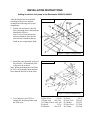
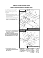
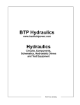
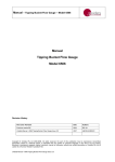
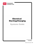
Customer Service Bulletin
Commercial Business Group
Reelmaster® 5000 Series
Model/Serial Range: Model Number:
03540-03544
03550-03551
Subject:
Date: January 18, 2005
Serial Numbers:
90101-210999999
200000101-210999999
When replacing a complete engine a different fuel Pump is required.
Units within the serial range listed used a manual lift pump. Current units incorporate
an electric fuel pump and have no provision for a manual lift pump. When the engine is
ordered for any unit, it will cross reference to the most current version of that engine.
Since the most current version of the engine will have no provision for the original fuel
pump, an electric fuel pump must be fitted.
Refer to the attached instruction pages for the mounting location, parts, and hardware
required to fit an electric fuel pump to the units listed above.
The following parts will need to be ordered for the respective product.
Qty
1
1
1
1
2
1
2
1
3
3
1
Part Required for 5200-D and 5400-D
Part Number
Description
104-5197
Jumper, Wire
104-5214
Pump, Fuel
104-9333
Bracket
2412-48
Clamp
2412-108
Clamp, Worm
27-5360
Hose
321-4
Screw
321-6
Screw
3256-22
Washer
3296-42
Nut, Lock
8-7612
Filter, Fuel
Ref: LR03-07.doc Copyright, 2003. The Toro Company
Qty
1
1
1
1
2
5
2
5
1
1
Part Required for 5500-D
Part Number
Description
104-5197
Jumper, Wire
104-5215
Pump Fuel
104-9339
Bracket
2412-48
Clamp
2412-108
Clamp, Worm
321-4
Screw
3256-22
Washer
3296-42
Nut, Lock
47-7430
Hose
8-7612
Filter, Fuel
INSTALLATION INSTRUCTIONS
Adding an electric fuel pump to the Reelmaster 5200-D & 5400-D
After the Engine has been installed
according to the Service manual
exchange the following fuel system
components.
Form # 3326-300
1. Lift the seat and remove the fuel
filter, mounting pieces and hardware
identified in Figure 1.
Note: For your convenience the
reference numbers listed are the
same reference numbers that are
found in your original parts book.
Figure 1 (original configuration)
2. Install the parts identified in figure 2
for reference. All numbered parts
will need to be ordered.
Note: When positioning the Fuel Filter
(8-7612) verify that the outlet remains
lower than the fluid level in the filter.
Form # 3326-750
Figure 2 (newest configuration)
3. Use Connector (104-5197) to
connect the fuel pump inline with
the ETR valve.
2) Filter, Fuel. . . . . .. 8-7612
3) Pump, Fuel. . . . 104-5215
11) Clamp, Worm. 2412-108
28) Screw. . . . . . . . . . .321-6
30) Bracket. . . . . . 104-9333
31) Screw. . . . . . . . 321-4
32) Nut, Lock. . . 3296-42
33) Washer. . . . . 3256-22
35) Line, Fuel. .. .27-5360
36) Clamp. . . . . .2412-48
INSTALLATION INSTRUCTIONS
Adding an electric fuel pump to the Reelmaster 5500-D
After the Engine has been installed
according to the Service manual
exchange the following fuel system
components.
Form # 3326-608
1. Lift the seat and remove the fuel
filter, mounting pieces and hardware
identified in Figure 1.
Note: the reference numbers are the
same reference numbers that are
found in your original parts book.
Figure 1 (original configuration)
2. Install the parts identified in figure 2
for reference. All numbered parts
will need to be ordered.
Note: When positioning the Fuel Filter
(8-7612) verify that the outlet remains
lower than the fluid level in the filter.
Form # 3327-537
Figure 2 (newest configuration)
3. Use Connector (104-5197) to
connect the fuel pump inline with
the ETR valve.
2) Filter, Fuel. . . . . . . 8-7612
3) Pump, Fuel. . . . .104-5215
11) Clamp-Worm. .2412-108
30) Nut, Lock. . . . . .3296–42
31) Screw. . . . . . . .321-4
33) Hose. . . . . . . 47-7430
34) Washer. . .. . .3256-22
35) Bracket. . . . 104-9339
36) Clamp. . . . . .2412-48