1
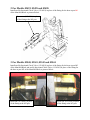
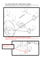
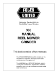
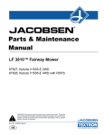
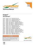
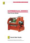
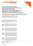
Customer Service Bulletin
Commercial Business Group
Date: March 20, 2006
Reelmaster® 2000, 2300, 2600, 3100, 5200, 5400, 5500, 6500 and 6700
Greensmaster® 3150, 3200 and 3250
Model/Serial Range: Model Numbers:
03200, 03201
03422, 03427
03428
03540, 03541
03543, 03544
03550, 03551
03806, 03807, 03808
04357
04380, 04381
04382
04383
Subject:
Serial Numbers:
90101 - 250009999
60101 - 210009999
220000101 - 260009999
80101 - 260009999
90101 - 260009999
200000101 - 260009999
210000101 - 260009999
220000101 - 250009999
50101 - 90101
60101 - 60999
200000101 - 260009999
Reels may continue to rotate in the ‘Off” or “Disabled” position
While the engine is running the reels may rotate, slowly or without force, after being
turned “Off” or “Disabled” due to normal tolerance variations and inefficiencies in
hydraulic circuitry. The rotation is usually prevented with the resistance created by light
reel-to-bedknife contact, reel bearing load and tight tolerances in drive components.
This rotation normally does not occur when proper maintenance is followed (refer to
service list below), and the unit is operated in a manner that does not overheat the
hydraulic system. This situation may be more noticeable if the recommended
maintenance and bedknife contact is not maintained.
Warning:
As with any cutting unit, NEVER use your hands or attempt to
manually stop a reel that is turning, no matter what speed or conditions are in
effect.
Should you discover that the reels rotate after being turned “Off” or while in the
“Disabled” position, perform the following steps:
• Reel bearing preload properly adjusted
• Light reel-to-bedknife contact
• All bearings and pivots are greased properly
• Reel motor efficiency is within specifications
Refer to the Operator’s Manual or Service Manual for proper service and repair
information.
Ref: Gen. 08-02.doc Copyright, 2006. The Toro Company
Should the reels continue to rotate after verification that the items mentioned are
working and adjusted properly, perform the following steps for the model in question:
03200 and 03201
• Install one Bi-Directional Check Valve (112-0201) according to the attached
instructions
03422, 03427 and 03428
• Install one Bi-Directional Check Valve (112-0201) according to the attached
instructions
03540, 03541, 03543 and 03544
• Perform the Customer Service Bulletin dated March 31, 2005
• Install two Bi-Directional Check Valves (112-0201) according to the attached
instructions
03550 and 03551
• Install two Bi-Directional Check Valves (112-0200) according to the attached
instructions
03806, 03807 and 03808
• Install two Bi-Directional Check Valves (112-0200) according to the attached
instructions
04357, 04380 - 04383
• Install one Bi-Directional Check Valve (112-0201) according to the attached
instructions
Contact your local Authorized Toro Distributor for additional information or assistance
with this kit installation.
INSTALLATION INSTRUCTIONS
For Bi-Directional Check Valves (112-0200 and 112-0201)
Male
Female
Male
Male
O-ring Face seal
O-ring Face Seal
O-ring Face seal
SAE Fitting
Hose End
112-0200
Flow
Hose End
Flow
Note: torque to the same specifications as the current fittings
112-0201
1. For Models 03200 and 03201
Install one Bi-directional Check Valve (112-0201) in place of the fitting for the hose at port M2
of the Manifold Block as pictured below.
Insert one (112-0201) in place
of the fitting at the M2 port
2. For Models 03422, 03428 and 03428.
Install one Bi-directional Check Valve (112-0201) in place of the fitting for the hose at port M1
of the Manifold Block as pictured below.
Insert one (112-0201) in place
of the fitting at the M1 port
3. For Models 03540, 03541, 03543 and 03544
Install one Bi-directional Check Valve (112-0201) in place of the fitting for the hose at port M3
of the Manifold Block and one Bi-directional Check Valve (112-0201) in place of the fitting for
the hose at port M5 of the Manifold Block as pictured below.
Insert one (112-0201) in place
of the fitting at the M5 port
Insert one (112-0201) in place
of the fitting at the M3 port
4. For Models 03550, 03551, 03806, 03807 and 03808.
Install one Bi-directional Check Valve (112-0200) in line at each fitting for the reel motor in the
number two and the number four cutting unit position as pictured below.
5. For Models 04357, 04380, 04381, 04382 and 04383
Install one Bi-directional Check Valve (112-0201) in place of the front fitting for the hose at the
left front motor as pictured below.
Insert one (112-0201) in place
of the front fitting at the left
front reel motor.