1
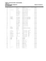
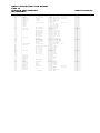
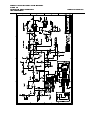
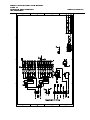
INSTRUCTION MANUAL
MODEL 6060
PULSE LINK EXTENDED RANGE
NEUTRON AREA MONITOR
October 1994
Version 2A
Health Physics Instruments
330 South Kellogg Ave, Suite D
Goleta, CA 93117
(805) 967-8422
Division of Far West Technology
MODEL 6060 INSTRUCTION MANUAL
PAGE 1
NEUTRON AREA MONITOR
INSTRUMENTS
HEALTH PHYSICS
INTRODUCTION
The model 6060 is an extended range neutron area monitor. It is designed to be powered by a HPI
Pulse link Receiver. The 6060 produces a pulse output. The instrument has many adjustments and
features to make it easy to set up and use.
II. DESCRIPTION AND CONTROLS
The model 6060 consists of two sections; the electronics/detector and the moderator. All of the
controls and connections are on one side of the electronics package (see Fig. 1).
Digital Counter: This is a 6 digit up counter that counts up with every pulse that is transmitted on
the Pulse Link.
Counter Reset: Reset for the Digital Counter.
Pulse Link Connection: This is a BNC connector that should be connected to the input to a Pulse
Link Receiver through coax. Both power and data are transmitted on this connection.
Accessory Connector: This connector contains signals for testing and operating the instrument.
The connections are detailed below.
III. INSTALLATION
The model 6060 is installed by plugging it into a Pulse Link Receiver. The BNC on the panel of the
6060 should be mated to the input on the Pulse Link Receiver through a patch cord with a BNC on
each end. The counter should be reset after turn on to make it count properly.
MODEL 6060 INSTRUCTION MANUAL
PAGE 2
NEUTRON AREA MONITOR
INSTRUMENTS
HEALTH PHYSICS
Figure 1 Location of Controls
IV. ACCESSORY CONNECTION
The accessory connection is a window into the instrument. All of the normal adjustments can be
made from outside the 6060 without having to remove the cover. The pin definitions are:
PIN #
DESCRIPTION
A
Discriminator +
B
Discriminator C
Test pulse input
D
HV Monitor
E
Amplifier output
F
RS232 Transmit
G
RS232 Receive
H
Reset
J
Wakeup
K
Output pulse
L
Ground
M
External power
N
+5 VDC output
Connector type:
Cannon KPT, 15 pin. Part Number KPT06J14-15P
PIN FUNCTIONS AND DESCRIPTIONS:
D i s c r i m i n a t o r : This is an output of the discriminator level. It is measured between pin A and B.
If you are using a DVM put the negative lead on B and the positive lead on A. A negative value
indicates that the discriminator is below the signal level.
T e s t p u l s e i n p u t : This is a test pulse input. Connect a pulse generator or a mercury pulser to
this input. The test pulse should be negative going. It is terminated in 51 ohm.
H V M o n i t o r : This is a buffered output that is proportional to the high voltage. Its sensitivity is
1.00 volt output per 1000 volt high voltage applied to the detector.
A m p l i f i e r O u t p u t : This is a buffered output of the signal before the discriminator.
R S 2 3 2 T r a n s m i t : This is an RS232 output. Baud rate is 9600.
R S 2 3 2 R e c e i v e : This is an RS232 input. Baud rate is 9600.
W a k e u p : This is an input that is used to keep the microprocessor alive. The microprocessor will
turn itself off after turn on or reset if this pin is open. Grounding this pin will keep the microprocessor
alive and the RS232 communications open. Whenever the pin is no longer grounded, the
microprocessor will turn itself off which will terminate the RS232 communications.
MODEL 6060 INSTRUCTION MANUAL
PAGE 3
NEUTRON AREA MONITOR
INSTRUMENTS
HEALTH PHYSICS
R e s e t : This is an input that resets the microprocessor. When this pin is brought high by
connecting it to the +5VDC output (pin N) the microprocessor will be reset. This is usually done with
a push-button. When the microprocessor is reset it sets the High Voltage, Discriminator, and Gain to
the stored values.
O u t p u t p u l s e:
e This is an LSTTL positive going output pulse for each discriminated event. This is
not a buffered signal, however it will drive 1 LSTTL load.
G r o u n d : Signal and power ground. This is the negative input for external power.
E x t e r n a l P o w e r : This is the positive input for external power. It can power the instrument instead
of or with the Pulse Link. The external power should be above 9 volts. The instrument can be
powered continuously by connecting external power to this input before removing the Pulse Link
connection.
+ 5 V D C O u t p u t : This is an output of 5 volts. This is the positive connection. The Ground pin is
the negative connection. It is used for the external reset switch and if needed to power external
devices.
V. TEST BOX
Interrogation and adjustment of the 6060 depends on connections to the accessory socket. A
schematic of a recommended test box is shown in figure 2. The model 6120 Breakout box is available
from HPI. The user may wish to construct whatever test box or connections they may need. To
calibrate the instrument all you need is to wire pin J to L, provide a push-button switch from pin H to
N and connect an RS232 to pin F,G and L. If you want to provide test points for the various signals,
they can also be included.
Figure 2 Test Box Schematic
MODEL 6060 INSTRUCTION MANUAL
PAGE 4
NEUTRON AREA MONITOR
INSTRUMENTS
HEALTH PHYSICS
VI. OPERATION
Once you have a test box you can begin to interrogate the instrument. Plug it into the 6060 with either
power from the Pulse Link or external power connected to the test box itself.
A. Connect the serial port to a terminal or terminal emulator. The setting is 9600 baud, 8 bits, no
parity, 1 stop bit.
B. Switch the wakeup switch so that pin J (wakeup) is connected pin L (ground).
C. Turn the power on. The terminal should show a screen similar to the following:
HPI 6060/6020 MONITOR VER 1.0
HV: 0200
DISC: 1C
GAIN: 04
LOG: 1234
LOGE: 5678
*
The * is the prompt. The values may be different depending on the settings of that unit. If you do
not receive this display try toggling power again. The instrument will always send out a message
even if the wakeup switch is not activated. Pushing the reset switch does the same thing as turning
on the power. (You can also use the internal reset switch. See the section on Internal Adjustments
and Controls.) If the instrument has power and the reset button is pushed it should send out a
message. If
the wakeup switch is not energized it will send out:
Sleep Mode
It also sends out this message whenever it goes into the sleep mode. To be able to interrogate the
instrument you need to have the wakeup switch in the closed position. This allows communication
with the instrument. Use the Commands listed in the next section to talk to the instrument to change
the High Voltage, Set the Discriminator, Set the Gain or use it as a Scaler/Counter.
VII. COMMANDS
The following table contains a brief listing of the commands. Following this table is a complete
description of the commands. There is also a help command that will display the help menu.
KEY Action
Hxxx Sets HV xxx is 3 hex bytes: range 0 to max
U
Increments HV
N
Decrements HV
Dxx Sets Discriminator xx is 2 hex bytes: range 0 to 3F
R
Increments Discr
C
Decrements Discr
Gx
Sets Gain x is one byte: range 0 to 7
Y
Increments Gain
B
Decrements Gain
S
Shows all variables
O
Reads EEPROM
P
Programs EEPROM with current settings
Q
Presets HV, DISCR and Gain w/ defaults
L or E Logs 4 hex digits
T
Test routine
Xxxxxxxxx download HV,Discr,Gain
Zxx Count for xx hex seconds and report counts
MODEL 6060 INSTRUCTION MANUAL
PAGE 5
NEUTRON AREA MONITOR
INSTRUMENTS
HEALTH PHYSICS
ESC cancels a command, ? or / for Help
A
Displays maximum HV (#xxxx sets)
A. Command Structure
The High Voltage, Discriminator and Gain all have a similar command structure. You can change them
two ways. The first way is to set them directly. To change the high voltage, for example, type the
letter H followed by the new setting. H200 would set the high voltage to 200. The other way to set it is
to increment or decrement the high voltage. If the high voltage is at 200 and you push U then the
high voltage will go to 201. Every time you push U it will increment. Likewise N will decrement it by
one.
The location of the keys is important. The changes to High Voltage, Discriminator, and Gain can all be
set by typing the first letter of their names. H for High Voltage, D for Discriminator and G for Gain.
Likewise the keys to increment the values are all above them, and the keys to decrement the values
are all below them. Of course in a QWERTY keyboard the keys are not arranged exactly above and
below each other, they are skewed so we took some liberty in their locations. The increment and
decrement keys are actually above and to the right, and down and to the right.
B. Numeric format.
All settings and values are in HEX. Setting High Voltage to 200 will set it to 200 HEX or 512 Decimal.
Setting it to 1EB will set it to 1EB HEX which is 491 Decimal.
C. Data Entry.
The data that is entered is all entered right digit justified. This allows you to make a mistake and just
keep typing until the values are correct. Thus H10234 would set High voltage to 0234. H12310122
would set High voltage to 0122. The entry also does not need leading zero's. Thus H5 would set it to
005. All the values have limits. Trying to set the value above the limit or below 0 will set them at their
respective limits. Upper and lower case are both accepted. ESC will cancel any command.
D List of commands:
1. Setting High Voltage
Hxxx This sets the High voltage to the value xxx. Where xxx is from 0 up to max. The max is set
under the A or HV max command. After changing the HV allow a few seconds for it to settle to its new
value.
U Increments the High voltage by 1.
N Decrements the High voltage by 1.
2. Setting the Discriminator
Dxx Sets the Discriminator to the value xx. Where xx is from 0 to 3F.
R Increments the Discriminator by 1.
C Decrements the Discriminator by 1.
3. Setting the Gain
Gx Sets the Gain to the value x. Where x is from 0 to 7.
Y Increments the Gain by 1.
B Decrements the Gain by 1.
4. Showing the current value of the variables
S
This will Show the current settings of High Voltage, Discriminator and Gain.
5. Reading the stored values of the variables.
O This will show the values of the High Voltage, Discriminator and Gain that are stored in the
EEPROM. You may want to think of this as the old readings if you have changed them.
6. Programming the EEPROM with the current values.
Gain.
P
This will Program the EEPROM with the current settings of High Voltage, Discriminator and
7. Presetting the Variables
MODEL 6060 INSTRUCTION MANUAL
PAGE 6
NEUTRON AREA MONITOR
INSTRUMENTS
HEALTH PHYSICS
Q
This Sets up the variables as follows:
High Voltage: 100
Discriminator: 1C
Gain: 03
This is useful with a new EEPROM as a starting point. It does NOT save the values in EEPROM.
Think of this as Querying the EEPROM.
8. Test Routine
T This is for Testing the circuitry. It will do the following:
A. Turn off the high voltage.
B. Continuously increment the High Voltage DAC until it reaches the maximum then reset it to
zero. This can be observed on test point TP7.
C. Continuously increment the discriminator DAC until it reaches the maximum then reset it to
zero. This can be observed on test point TP8. The staircase will be U shaped because of the
influence of capacitor C13.
To exit the routine type anything. High voltage and the discriminator will be restored to their
EEPROM values when it goes back to normal operation.
9. Help Menu
? or / This is the help menu. No variables are changed.
10. Downloading the data.
X0xxxxx0x Downloads the settings of the variables and sets them into EEPROM.
X is the command to start the download. The first four hex digits, 0xxx are the High voltage setting.
The next two hex digits, xx are the discriminator level, and the last two hex digits, 0x are the gain.
Send a 0 where noted. The values will not be echoed on the screen as they are typed. To exit this
routine it is necessary to type all 8 hex digits. ESC will not work.
NOTE: high voltage is checked against the maximum to prevent accidents.
11. Count for specified time.
Zxx This turns the 6060 into a scaler that will count for xx seconds. xx is from 0 to FF. After the
xx seconds it will send the number of counts it accumulated during that time. The number of counts is
reported as six hex digits that will count modulo 01XXXX hex. Thus it will count up to 01FFFF and the
next count will round it over to 000000. Entering 00 as the time will make it count continuously until it
receives another character, then it will send the number of counts. This allows extended counting
time. Typing ESC while it is counting will terminate the count and not show the counts.
12. Log a reference number.
Lxxxx or Exxxx This logs the two 4 digit hex numbers xxxx for log, and xxxx for logE and puts them
into EEPROM. They are displayed every time the S menu is displayed. You do not have to push P to
save this data. This can be used for serial numbers or anything else you want.
13. Max HV Setting.
A#xxxx This sets a maximum value that the high voltage can be set. It should be set from 0 to
3FF since this is the range of the high voltage power supply. Changing this value to a value lower
than the current high voltage will not change the high voltage until the high voltage is changed. Nor
will it alter a higher number in the eeprom until the eeprom is changed. Check if the high voltage is
higher than the setting when changing this value. It does use this value with the download command
to prevent accidents.
Typing A alone will not allow you to change the value, it just reports the value. This is to keep from
accidentally changing the value. To change the value, after typing A type "#" followed by the 4 hex
digits of the maximum level then <ENTER>. This puts the values in EEPROM for permanent storage.
E. High Voltage Values.
The high voltage setting is directly proportional to the high voltage. 200 hex is 1000 VDC and 3FF
hex is 2000 VDC. This means that each bit is about 1.95 volts. Use only the voltage necessary to
operate the detector properly. Too high a voltage on the detector may cause it to malfunction.
MODEL 6060 INSTRUCTION MANUAL
PAGE 7
NEUTRON AREA MONITOR
INSTRUMENTS
HIGH VOLTAGE SETTINGS IN HEX
VOLTAGE
HEX SETTING
VOLTAGE
500
100
1000
563
120
1062
625
140
1125
687
160
1187
750
180
1250
812
1A0
1312
875
1C0
1375
937
1E0
1437
HEALTH PHYSICS
HEX SETTING
200
220
240
260
280
2A0
2C0
2E0
VOLTAGE
1500
1564
1627
1690
1753
1815
1878
1940
HEX SETTING
300
320
340
360
380
3A0
3C0
3E0
F. Discriminator Values.
The discriminator setting is directly proportional to the discriminator voltage. Each discriminator bit
is about 0.042 volts. When the discriminator is set to zero it measures about -.3 volts across the two
outputs on the test box. With it set to 3F it measures about 1.95 volts.
G. Gain Values.
The gain of the first stage correlates to the gain setting as follows:
GAIN SETTING
0
1
2
3
4
5
6
7
GAIN
3.25
4.875
6.5
9.75
13
User installed resistor
1
0 Input tied to VCC selected during turn on and during reset.
We recommend that the gain be set to 0, 1, 2, 3, or 4. If the user wants to install a resistor then a
setting of 5 may be used. Gain setting 6 while indeed a DC gain of 1 will result in ringing on large
pulses and should not be used in this application.
H. Saving the data.
When you change the High Voltage, Discriminator, or Gain, you are just changing the value in the
RAM memory of the instrument. This is not the permanent EEPROM memory. When you first turn the
instrument on the values that are in the EEPROM are the ones used to set the High Voltage,
Discriminator and gain. When you change these values you are not changing them in the EEPROM,
just in the RAM. This permits you to try different things without altering the permanent settings. If
you want to save the values in the EEPROM then you need to do a P for program the EEPROM. This
puts the values in RAM into the EEPROM so the next time it is powered up or reset it will use those
values. If you decide you don't like the changes, just do an O instead of the P. This will read back the
original stored values.
Downloading data is assumed to be permanent and is stored both in RAM and in EEPROM. It is not
necessary to do a P.
V I I I . C A L I B R A T I O N / SE T U P
The output of the 6060 and thus the 6014 Pulse Link receiver is a series of pulses. These pulses are
uncalibrated. Each pulse in the detector that is above the threshold will be output from the 6060 and
6014. It is necessary to adjust all the parameters until the instrument has an output that is adjusted
MODEL 6060 INSTRUCTION MANUAL
PAGE 8
NEUTRON AREA MONITOR
INSTRUMENTS
HEALTH PHYSICS
for the specific detector. This is accomplished by adjusting all the parameters until they are optimized
for this detector. Only when the detector is optimized can the counts per mrem be determined.
The normal procedure for testing the instrument is to adjust the high voltage while the gain and
discriminator are fixed at their operational values. Normal operation is with the gain set to 4 and the
discriminator set to 10 hex. The high voltage is adjusted in 10 hex increments from 200 hex to 3F0 hex
while the instrument is exposed to around 500 mrem/h of neutrons. Count the counts from the
detector for 10 seconds at each high voltage setting and note the counts. Plot the data in graphical
form and set high voltage just above the knee of the curve. The example on Graph 1 shows this plot
and the high voltage would be set at around 1300 volts. This assures that the high voltage is as low
as possible for environmental reasons, but also high enough that a change in high voltage will not
produce a significant change in the count rate of the instrument. Set this high voltage into the
instrument and expose it to a known doserate of neutrons and not the counts/mrem/h. This is the
calibration of the output of the 6060 and also of the 6014.
Graph 1 High Voltage Plateau
PROCEDURE TO CALIBRATE THE MODEL 6060
1. Connect the instrument to a power supply through the 15 pin accessory connector on the front
panel or through the test box.
2. Connect the instrument to a terminal with the RS-232 signals available on the 15 pin accessory
connector on the front panel of through the test box.
3. Turn the instrument on with the wakeup switch on the test box closed or with pins J and L .
4. Verify that the terminal is connected to the instrument by hitting <ENTER>. a couple of times.
Each time the screen should show an *.
MODEL 6060 INSTRUCTION MANUAL
PAGE 9
NEUTRON AREA MONITOR
INSTRUMENTS
HEALTH PHYSICS
5. Push S for show and look at the current settings.
6. Set the discriminator to 10 hex by typing D10 <ENTER>.
7. Set the gain to 4 by typing G4 <ENTER>.
8. Set the high voltage to its lowest value for this test by pushing H200 <ENTER>.
9. Turn on the source and expose the instrument to around 500 mrem/h.
10. Start a 10 second count by typing ZA <RETURN> and note the result along with the high voltage
for that result.
11. Increment the high voltage by 10 hex. Repeat step 9 and 10 until the high voltage is at 3F0 hex.
12. Plot the high voltage and counts on a graph and set the high voltage to the value that represents
a short way up the knee of the curve.
13. Expose the instrument to a known radiation field. Calculate the counts/mrem/h. This is the
calibration for the instrument. Make sure before turning off the instrument that you push P to
program the values in EEPROM so that these are the values that the instrument will use from now on.
The exposure rate can be lower than 500 mrem/h but it is not a good idea to go over 1000 mrem/h.
Adjust the time so that you scale over 10,000 counts when the high voltage is set to its higher values.
IX. CONSTRUCTION
The electronics is all housed inside the cast aluminum case. The case is gasketed and sealed. To
gain access to the circuit boards, remove the four large screws on top of the case and remove the
top. The small circuit board containing the microprocessor is hinged on the end with the ribbon
connector, the other end is screwed with two screws to two standoffs. Removing these two screws
will permit the board to be raised to a vertical position. Remove the three screws on the larger circuit
board to loosen it. To remove the large board hold the small board vertically and slide the large board
out away from the controls on the front panel.
Before removing the circuit board, it is a good idea to short the high voltage to ground to keep from
destroying any part of the instrument by getting your hand between high voltage and any component.
In the corner of the high voltage section, there is a 10 meg resistor mounted to a terminal. Touch the
end of an insulated screwdriver between this terminal and the high voltage.
The desiccant is mounted in the lid. Make sure that it is replaced or baked out for 3 hours at 300 °F if
it is pink. It can also be put in a vacuum to remove the moisture.
The detector is mounted to a long piece of wire. This wire has RTV around it where it protrudes
through the insulator inside the box. This keeps moisture from entering the case. All controls and
screws and openings are treated with RTV silicone sealant to keep the box from breathing with
atmospheric pressure changes.
X. CIRCUITRY
A. Analog Circuitry (DWG 6060-001 to -003)
The incoming signal is amplified by U1B. This is a noninverting voltage amplifier. The current from the
detector flows through R13 and creates the voltage that is amplified. The gain of this stage can be
changed by the multiplexer, U5 that switches in different feedback resistors. The multiplexer has 3
inputs that control it. A,B and C select which resistor is to be included in the circuit.
A reference voltage created by R88 and R21 and filtered by C12 and C11 is used by all the op amp
stages. It is in effect an artificial ground between true ground and VCC. All the op amps are
decoupled from the power supply by series resistors and filter capacitors.
The next stage is capacitively coupled (C8) and has a gain of 7.5. It is a inverting amplifier. The stage
after that, U4:A is direct coupled and is a noninverting amplifier with a gain of 13.
The next stage is the discriminator U3. This discriminates the signal on pin 3 from the threshold set
on pin 2. The resultant pulses on pn 7 are capacitively coupled to U2, a multivibrator. This makes
sure that the output pulses are of uniform proper width. The output pulses then go to Q2 to enter
MODEL 6060 INSTRUCTION MANUAL
PAGE 10
NEUTRON AREA MONITOR
INSTRUMENTS
HEALTH PHYSICS
them into the Pulse Link cable. The output of the amplifier is buffered by U4:B before going to the test
point.
The High voltage power supply starts out as a multivibrator U9. The pulses from the multivibrator are
amplitude modulated before being fed thru Q4 and Q3 to the transformer. This is a step up
transformer that is followed by a voltage multiplier. The output is restively divided (R37, R49) and
compared to a reference HVSET. The pulse heights from the multivibrator are thus controlled before
going into the transformer to keep the HV output at the required level. The high voltage signal is
buffered by U10:C before going to a test point.
The low voltage power supplies of 5 volts, and 6 volts are isolated from the pulse link by two chokes.
Power is derived from the Pulse Link line. The two three terminal regulators U7 and U8 regulate the 5
volt and 6 volt supplies. Testpoints are provided for both.
The HVSET and DISCR signals are derived from the DACs made up of U11 and U12. These are serial
to parallel converters that load the data onto their outputs. The R - 2R ladder networks convert this
digital data into an analog value. For testing the DACs see the test routine under Commands.
The counter/display increments on every count. It has a panel mounted reset switch, S1.
B. Digital Circuitry (DWG 6060-001M)
The digital signals are handled by the microprocessor. It generates the signals for the DACs, and the
gain. In addition it generates the RS232 signals for communication. The digital circuitry is on a
separate circuit board.
The microprocessor U4 is connected to the address latch U1. The address lines, A0 to A7 are used
by the EPROM U5 which contains the program. The EEPROM that stores the permanent data is U2.
U8 is the RS232 driver and receiver. In addition it generates the voltages needed for RS232. The
reset circuitry U9A and U9B is used to generate the Reset signal if VCC is too low to operate. When
the microprocessor is reset all the output lines P10 to P17 and P30 to P37 go high. The resistor
network
R2 pulls some of them up with more current than is supplied by U4 alone. U11, U7, U12, and U3 are
not used but are available for future expansion.
XI. INTERNAL ADJUSTMENTS AND CONTROLS
A. ADJUSTMENTS
The High Voltage, Discriminator, and Gain are all controlled by the RS232 communications link. There
is no way to adjust them without this link.
The only remaining adjustment is the reset voltage adjustment. It is factory set and should never
need adjustment. This resets the microprocessor when the VCC voltage falls below a preset level.
The adjustment is the 20 turn trimmer (R5) on the small digital circuit board mounted on top of the
main board.
To set it, connect the unit to a variable power supply through the test box. Then connect a voltmeter
between the ground (TP1) and +5 Volt (TP2) test points on the digital circuit board (the small one on
top). We want to measure the actual voltage on the 5 volt supply. Turn the trimmer R5 Clockwise 20
turns or until you feel it clicking. This should turn on the microprocessor and take it out of reset.
Then adjust the power supply voltage to the unit until the voltmeter decreases by .20 volts. Then
turn the trimmer R5 counter clockwise 20 turns or until you feel it clicking. This will turn on the reset
signal. Then slowly turn the trimmer R5 Clockwise until the signon message on the terminal appears.
This should be the correct setting. This is the voltage where the microprocessor will go into reset.
This is important for both power on and power off.
B. CONTROLS
The only control is the reset button located on one end of the small digital board mounted on top of
the main board. Pushing it will reset the microprocessor and has the same effect as turning power off
and back on or pushing the reset button in the external test box.
MODEL 6060 INSTRUCTION MANUAL
PAGE 11
NEUTRON AREA MONITOR
INSTRUMENTS
HEALTH PHYSICS
XII. MODIFICATIONS
There are several modifications that can be built into the instrument. On the digital side, the
instrument is set up to handle an alphanumeric LCD. This can be plugged into U3. The LCD will
usually need a negative supply for the contrast. This is supplied by U6. The contrast would be
adjusted by R1.
Communications does not have to be RS-232. Built in is an RS-485 interface, U11 along with the
terminating resistors and pull up/down resistors or the bus. The digital board can also be operated
separately from the main board and has its own 5 volt regulator, U12. Expansion of the board can use
the signal generated by U7:D. There is a jumper to permanently disconnect the RS-232 driver to
reduce power consumption.
The main analog board also has some unused features. The high voltage and discriminator can both
be changed from computer control to fixed trimmers, R54 and R23 respectively. There is a location for
a user selected gain resistor, R_USER in the preamp. The high voltage can be turned on without the
computer control by using JP4.
MODEL 6060 INSTRUCTION MANUAL
PAGE 12
NEUTRON AREA MONITOR
INSTRUMENTS
DESIGN QUAN PART NO
------ ----- -------------------C01
1
C02
1
C03
1
C04
1
C05
1 570B1L202M
C06
1
C07
1
C08
1
C09
1
C10
1
C11
1
C12
1
C13
1
C14
1
C15
1
C16
1
C17
1
C18
1
C19
1 Not Used
C21
1 30GASS10
C21
1 30GASS10
C22
1 30GASS10
C23
1 30GASS10
C24
1 30GASS10
C25
1 520BIL103M
C26
1
C27
1
C28
1
C29
1
C30
1
C31
1
C32
1
C33
1
C34
1
C35
1
CX1
1
CX2
1
CX3
1
CX4
1
CX5
1
D1
1 1N4148
D2
1 1N4004
D3
1 BYV26EPH
D4
1 BYV26EPH
D5
1 BYV26EPH
D6
D7
D8
J1
1 CSC20G
J2
1 22-01-3147
J3
1 22-01-3047
J4
1 22-01-3047
J6
1 22-01-3027
J7
1 CSC20G
L1
1 434-05-103J
L2
1 434-05-103J
P2
1 22-23-2141
P3
1 22-23-206
P4
1 22-01-3027
P4
1 22-23-2041
P6
1 22-23-2021
P7
1 2520-6002UB
PCB1
1 6060-004
Q01
1 2N2222
Q02
1 2N2222
Q03
1 2N2905
Q04
1 2N3251
Q05
1 2N2222
Q06
1 2N2222
R01
1
R02
1
R03
1
R04
1
R05
1
R06
1
R07
1
R08
1
R09
1
R10
1
R11
1
R12
1
R13
1
R14
1
R15
1
R16
Not Used
R17
1
R18
1
TYPE
-------------------Tantalum
Z5U Cer Mono
Tantalum
Tantalum
Film 20%
Tantalum
NPO Cer Mono
NPO Cer Mono
NPO Cer Mono 5%
NPO Cer Mono 5%
Tantalum
Z5U Cer Mono
Z5U Cer Mono
Z5U Cer Mono
Electrolytic
Tantalum
Electrolytic
Tantalum
Y5V Cer Disk
Y5V Cer Disk
Y5V Cer Disk
Y5V Cer Disk
Y5V Cer Disk
Film 20%
Z5U Cer Mono
COG Cer Mono
Z5U Cer Mono
NPO Cer Mono
NPO Cer Mono
Z5U Cer Mono
Z5U Cer Mono
NPO Cer Mono
Z5U Cer Mono
Tantalum
Tantalum
Z5U Cer Mono
Z5U Cer Mono
Z5U Cer Mono
Z5U Cer Mono
Hi Speed
1000V 1A
1000V 1A
1000V 1A
1000V 1A
Not used
Not used
Not used
20 Pin .1 x .1
14 Pin
4 Pin
4 Pin
2 Pin
20 Pin .1 x .1
10 mH 90 mA
10 mH 90 mA
14 Pin
6 Pin
2 Pin
4 Pin
2 Pin
20 Pin LP MT
FR4
NPN
NPN
PNP
PNP
NPN
NPN
CF 5% 1/4 W
CF 5% 1/4 W
CF 5% 1/4 W
CF 5% 1/4 W
CF 5% 1/4 W
CF 5% 1/4 W
CF 5% 1/4 W
CF 5% 1/4 W
CF 5% 1/4 W
CF 5% 1/4 W
MF 1% 1/4 W
MF 1% 1/4 W
MF 1% 1/4 W
MF 1% 1/4 W
CF 5% 1/4 W
CF 5% 1/4 W
MF 1% 1/4 W
HEALTH PHYSICS
6060 PARTS LIST
DESCRIPTION
-------------------Capacitor 10 uF 10V
Capacitor .1 uF 50V
Capacitor 10 uF 10V
Capacitor 10 uF 10V
Capacitor .002uF 3KV
Capacitor 10 uF 10V
Capacitor 470 pF 50V
Capacitor .001uF 50V
Capacitor 100 pF 50V
Capacitor 100 pF 50V
Capacitor 10 uF 10V
Capacitor .1 uF 50V
Capacitor .1 uF 50V
Capacitor .1 uF 50V
Capacitor 330 uF 25V
Capacitor 33 uF 10V
Capacitor 330 uF 25V
Capacitor 33 uF 10V
Capacitor
Capacitor .01 uF 3KV
Capacitor .01 uF 3KV
Capacitor .01 uF 3KV
Capacitor .01 uF 3KV
Capacitor .01 uF 3KV
Capacitor .01 uF 3KV
Capacitor .1 uF 50V
Capacitor .1 uF 50V
Capacitor .1 uF 50V
Capacitor 470 pF 50V
Capacitor .022uF 50V
Capacitor .1 uF 50V
Capacitor .1 uF 50V
Capacitor .001uF 50V
Capacitor .1 uF 50V
Capacitor 33 uF 10V
Capacitor 10 uF 10V
Capacitor .047uF 50V
Capacitor .047uF 50V
Capacitor .047uF 50V
Capacitor .047uF 50V
Diode
Rectifier
Rectifier,Ultra fast
Rectifier,Ultra fast
Rectifier,Ultra fast
Diode
Diode
Diode
Connector, Socket
Connector, Housing
Connector, Housing
Connector, Housing
Connector, Housing
Connector, Socket
Choke
Choke
Connector, Header
Connector, Header
Connector, Housing
Connector, Header
Connector, Header
Connector, Header
Pc Board Detector
Transistor
Transistor
Transistor
Transistor
Transistor
Transistor
Resistor, 100 Ohm
Resistor, 1M
Resistor, 7.5K
Resistor 100 ohm
Resistor 100 ohm
Resistor, 2.7K
Resistor, 1K
Resistor, 1K
Resistor, 10K
Resistor, 4.7K
Resistor, 12.0K
Resistor, 12.0K
Resistor, 1.00M
Resistor, 1.00K
Resistor 51 ohm
Resistor
Resistor, 1K
Resistor, 1.38K
MFG
SUPPLIER
DRAWING #
---------- ---------- --------6060-001
6060-001
6060-001
6060-001
Ceramite
6060-001
6060-001
6060-001
6060-001
6060-001
6060-001
6060-001
6060-001
6060-001
6060-001
6060-001
6060-001
6060-001
6060-001
6060-001
Ceramite
6060-001
Ceramite
6060-001
Ceramite
6060-001
Ceramite
6060-001
Ceramite
6060-001
Ceramite
6060-001
6060-001
6060-001
6060-001
6060-001
6060-001
6060-001
6060-001
6060-001
6060-001
6060-001
6060-001
6060-001
6060-001
6060-001
6060-001
6060-001
6060-001
Philips
6060-001
Philips
6060-001
Philips
6060-001
6060-001
6060-001
6060-001
CW INDSTR
6060-001
Molex
6060-001
Molex
6060-001
Molex
6060-001
Molex
6060-001
CW INDSTR
6060-001
HiQ
6060-001
HiQ
6060-001
Molex
6060-001
Molex
6060-001
Molex
6060-001
Molex
6060-001
Molex
6060-001
3M
6060-001
HPI
6060-001
6060-001
6060-001
6060-001
6060-001
6060-001
6060-001
6060-001
6060-001
6060-001
6060-001
6060-001
6060-001
6060-001
6060-001
6060-001
6060-001
6060-001
6060-001
6060-001
6060-001
6060-001
6060-001
6060-001
6060-001
MODEL 6060 INSTRUCTION MANUAL
PAGE 13
NEUTRON AREA MONITOR
INSTRUMENTS
DESIGN QUAN PART NO
------ ----- -------------------R19
1
R20
1
R21
1
R22
1
R23
Not used
R24
1
R25
1
R26
1
R27
1
R28
1
R29
1
R30
1
R31
1
R32
1
R33
1
R34
1
R35
Not used
R36
1
R37
1 MOX-300
R38
1
R39
Not used
R40
1
R41
1
R42
1
R43
1
R44
1
R45
1
R46
1
R47
Not Used
R48
1
R49
1
R50
1
R51
1
R52
1
R53
1
R54
Not used
R55
1
R56
1
R57
1
R58
1
R59
1
R60
1
R61
1
R62
1
R63
1
R64
1
R65
1
R66
1
R67
1
R68
1
R69
1
R70
1
R71
1
R72
1
R73
1
R74
1
R75
1
R76
1
R77
1
R78
1
R79
1
R80
1
R81
1
R82
1
R83
1
R84
1
R85
1
R86
1
R87
Not Used
R88
1
R89
1
R90
Not Used
R91
1
R92
1
R93
Not Used
R94
1
R95
1
R96
1
R97
1
R_USER
Not Used
S1
1 MPE106F
SOC14
3
SOC16
4
SOC8
3
T1
1 M8149
U01
1 MC34072
U02
1 74LS221
U03
1 LM311
TYPE
-------------------CF 5% 1/4 W
MF 1% 1/4 W
CF 5% 1/4 W
MF 1% 1/4 W
MF
CF
CF
CF
CF
CF
CF
CF
CF
CF
CF
1%
5%
5%
5%
5%
5%
5%
5%
5%
5%
5%
1/4
1/4
1/4
1/4
1/4
1/4
1/4
1/4
1/4
1/4
1/4
W
W
W
W
W
W
W
W
W
W
W
CF 5% 1/4 W
10%
CF 5% 1/4 W
CF
CF
CF
CF
CF
CF
CF
5%
5%
5%
5%
5%
5%
5%
1/4
1/4
1/4
1/4
1/4
1/4
1/4
W
W
W
W
W
W
W
CF
MF
CF
CF
CF
CF
5%
1%
5%
5%
5%
5%
1/4
1/4
1/4
1/4
1/4
1/4
W
W
W
W
W
W
MF
MF
MF
MF
MF
MF
MF
MF
MF
MF
MF
MF
MF
MF
MF
MF
MF
MF
MF
MF
MF
MF
MF
MF
MF
MF
MF
MF
MF
MF
MF
MF
1%
1%
1%
1%
1%
1%
1%
1%
1%
1%
1%
1%
1%
1%
1%
1%
1%
1%
1%
1%
1%
1%
1%
1%
1%
1%
1%
1%
1%
1%
1%
1%
1/4
1/4
1/4
1/4
1/4
1/4
1/4
1/4
1/4
1/4
1/4
1/4
1/4
1/4
1/4
1/4
1/4
1/4
1/4
1/4
1/4
1/4
1/4
1/4
1/4
1/4
1/4
1/4
1/4
1/4
1/4
1/4
W
W
W
W
W
W
W
W
W
W
W
W
W
W
W
W
W
W
W
W
W
W
W
W
W
W
W
W
W
W
W
W
CF 5% 1/4 W
MF 1% 1/4 W
CF 5% 1/4 W
MF 1% 1/4 W
CF
CF
CF
CF
5%
5%
5%
5%
1/4
1/4
1/4
1/4
W
W
W
W
Push NO, Waterproof
DIP
DIP
DIP
Switching
Dual Hi Speed
Single
HEALTH PHYSICS
DESCRIPTION
-------------------Resistor, 10K
Resistor, 2.15K
Resistor, 20K
Resistor, 3.09K
Trimmer
Resistor, 5.36K
Resistor, 1K
Resistor, 10K
Resistor, 2.4M
Resistor, 10K
Resistor, 2.7K
Resistor, 2.7K
Resistor, 51
Resistor, 10M
Resistor, 10M
Resistor, 10M
Resistor
Resistor, 4.7K
Resistor, 1000M
Resistor, 560 Ohm
Resistor
Resistor 56K
Resistor, 680K
Resistor, 10K
Resistor, 100 K
Resistor, 1K
Resistor, 22K
Resistor, 4.7K
Resistor
Resistor, 200 Ohm
Resistor, 1.00M
Resistor 27K
Resistor, 10K
Resistor, 4.7K
Resistor, 100 K
Trimmer
Resistor, 100.0K
Resistor, 49.9K
Resistor, 100.0K
Resistor, 49.9K
Resistor, 100.0K
Resistor, 49.9K
Resistor, 100.0K
Resistor, 49.9K
Resistor, 100.0K
Resistor, 49.9K
Resistor, 100.0K
Resistor, 49.9K
Resistor, 100.0K
Resistor, 49.9K
Resistor, 100.0K
Resistor, 49.9K
Resistor, 100.0K
Resistor, 49.9K
Resistor, 100.0K
Resistor, 100.0K
Resistor, 100.0K
Resistor, 49.9K
Resistor, 100.0K
Resistor, 49.9K
Resistor, 100.0K
Resistor, 49.9K
Resistor, 100.0K
Resistor, 49.9K
Resistor, 100.0K
Resistor, 49.9K
Resistor, 100.0K
Resistor, 100.0K
Resistor
Resistor, 20K
Resistor, 100.0K
Resistor
Resistor, 10K
Resistor, 33.6K
Resistor
Resistor 100 ohm
Resistor, 10 Ohm
Resistor, 10M
Resistor, 1K
Resistor
Switch
Socket, 14 pin
Socket, 16 pin
Socket, 8 pin
Transformer
Op Amp
Monostable Multivib
Comparator
MFG
SUPPLIER
DRAWING #
---------- ---------- --------6060-001
6060-001
6060-001
6060-001
6060-001
6060-001
6060-001
6060-001
6060-001
6060-001
6060-001
6060-001
6060-001
6060-001
6060-001
6060-001
6060-001
6060-001
Victoreen
6060-001
6060-001
6060-001
6060-001
6060-001
6060-001
6060-001
6060-001
6060-001
6060-001
6060-001
6060-001
6060-001
6060-001
6060-001
6060-001
6060-001
6060-001
6060-001
6060-001
6060-001
6060-001
6060-001
6060-001
6060-001
6060-001
6060-001
6060-001
6060-001
6060-001
6060-001
6060-001
6060-001
6060-001
6060-001
6060-001
6060-001
6060-001
6060-001
6060-001
6060-001
6060-001
6060-001
6060-001
6060-001
6060-001
6060-001
6060-001
6060-001
6060-001
6060-001
6060-001
6060-001
6060-001
6060-001
6060-001
6060-001
6060-001
6060-001
6060-001
6060-001
6060-001
Alco
6060-001
6060-001
6060-001
6060-001
Microtran
6060-001
Motorola
6060-001
6060-001
6060-001
MODEL 6060 INSTRUCTION MANUAL
PAGE 14
NEUTRON AREA MONITOR
INSTRUMENTS
DESIGN QUAN PART NO
------ ----- -------------------U04
1 MC34072
U05
1 CD4051
U06
1 SCUB-1000
U07
1 LM340T-5.0
U08
1 LM340T-5.0
U09
1 CD4001
U10
1 TLC27L4
U11
1 CD4094
U12
1 CD4094
U13
1 CD4013
C01
1
C02
1
C03
Not Used
C04
Not Used
C05
1
C06
1
C07
1
C08
1
C09
1
C10
1
C11
Not Used
C12
1
CX1
1
CX2
1
CX3
1
CX4
1
D1
1
P1
1 2520-6002UB
R01
Not Used
R02
1
R03
1
R04
1
R05
1
R06
1
R07
Not Used
R08
1
R09
1
R10
1
R11
Not Used
R12
Not Used
S1
1 EVQ Type
U01
1 74HC573d
U02
1 93C46
U03
Not Used
U04
1 80C51
U05
1 27C256
U06
Not Used
U07
Not Used
U08
1 MAX232CP
U09
1 TLC27L2
U10
1 LM336-2.5
U11
1 Not Used
U12
Not Used
X1
1
TYPE
DESCRIPTION
-------------------- -------------------Dual Hi Speed
Op Amp
8 Input Multiplexer
6 Digit
Counter/Display LCD
5 VOLT
Voltage Regulator
5 VOLT
Voltage Regulator
Quad Nor Gate
Quad Low Power
Op Amp
S to P Sift Reg
S to P Sift Reg
D Type Flip Flop
NPO Cer Mono
Capacitor 22 pF
NPO Cer Mono
Capacitor 22 pF
Capacitor
Capacitor
Electrolytic
Capacitor 22uF 16V
Electrolytic
Capacitor 22uF 16V
Electrolytic
Capacitor 22uF 16V
Electrolytic
Capacitor 22uF 16V
Tantalum
Capacitor 10uF 10V
COG Cer Mono
Capacitor .1 uF 50V
Capacitor
Tantalum
Capacitor 10uF 10V
Z5U Cer Mono
Capacitor .047uF 50V
Z5U Cer Mono
Capacitor .047uF 50V
Z5U Cer Mono
Capacitor .047uF 50V
Z5U Cer Mono
Capacitor .047uF 50V
1N4148
Diode, High Speed
20 Pin LP MT
Connector, Header
Trimmer
10 Pin SIP Network
Resistor 10K x 9
CF 5% 1/4W
Resistor 100K
CF 5% 1/4W
Resistor 2.4K
20 T 3/8 SQ
Trimmer 100K
CF 5% 1/4W
Resistor 1M
Resistor
CF 5% 1/4W
Resistor 10M
CF 5% 1/4W
Resistor 10M
CF 5% 1/4W
Resistor 100K
Resistor
Resistor
Pushbutton NO
Octal Latch
Cmos 4 Wire
EEPROM
LCD Display
8 bit CMOS
Microprocessor
EPROM
7660
Volt Converter
74HC00
Quad Nand Gate
RS232
Line Drvr/Rcvr
Dual Cmos
Op Amp
Volt Reference
75176
Octal Latch
Voltage Regulator
7.3728 MHz
Crystal HC18
HEALTH PHYSICS
MFG
SUPPLIER
DRAWING #
---------- ---------- --------Motorola
6060-001
6060-001
Red Lion
6060-001
6060-001
6060-001
6060-001
Tex Inst
6060-001
6060-001
6060-001
6060-001
6060M-001
6060M-001
6060M-001
6060M-001
6060M-001
6060M-001
6060M-001
6060M-001
6060M-001
6060M-001
6060M-001
6060M-001
6060M-001
6060M-001
6060M-001
6060M-001
6060M-001
3M
6060M-001
6060M-001
6060M-001
6060M-001
6060M-001
6060M-001
6060M-001
6060M-001
6060M-001
6060M-001
6060M-001
6060M-001
6060M-001
6060M-001
6060M-001
6060M-001
6060M-001
6060M-001
6060M-001
6060M-001
6060M-001
6060M-001
Tex Inst
6060M-001
National
6060M-001
6060M-001
6060M-001
6060M-001
MODEL 6060 INSTRUCTION MANUAL
PAGE 15
NEUTRON AREA MONITOR
INSTRUMENTS
HEALTH PHYSICS
MODEL 6060 INSTRUCTION MANUAL
PAGE 16
NEUTRON AREA MONITOR
INSTRUMENTS
HEALTH PHYSICS
MODEL 6060 INSTRUCTION MANUAL
PAGE 17
NEUTRON AREA MONITOR
INSTRUMENTS
HEALTH PHYSICS
MODEL 6060 INSTRUCTION MANUAL
PAGE 18
NEUTRON AREA MONITOR
INSTRUMENTS
HEALTH PHYSICS
MODEL 6060 INSTRUCTION MANUAL
PAGE 19
NEUTRON AREA MONITOR
INSTRUMENTS
HEALTH PHYSICS