1
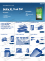
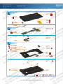
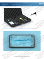
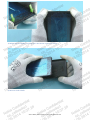
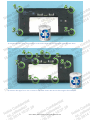
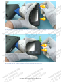
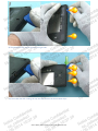
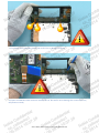
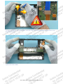
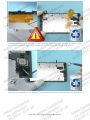
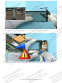
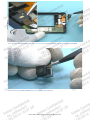
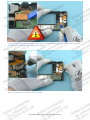
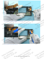
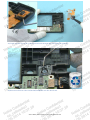
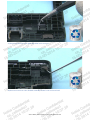
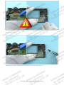
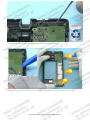
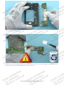
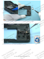
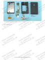
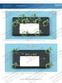
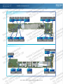
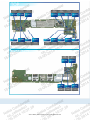
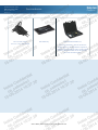
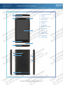
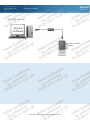
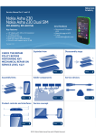
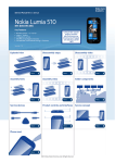
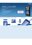
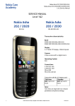
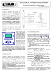
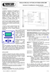
CONFIDENTIAL This document contains Nokia confidential material. This material cannot be shared except with persons that have a valid business reason to read this content. You are personally responsible to ensure recipients of this document are aware of information handling guidelines. © 2014 Nokia Company confidential Service Manual for L1 and L2 Nokia XL Dual SIM RM-1030, RM-1042 Send feedback Key features Fastlane to Android™ apps Dual SIM support 5.0" Display 1 GHz Dual-core CPU 5 MP Camera Recommend Change in KICS Rate this page in KICS E-mail [email protected] Version 1.0 Exploded view CHECK THE REPAIR POLICY BEFORE PERFORMING ANY MECHANICAL REPAIR ON SERVICE LEVEL 1&2! Disassembly steps More Assembly hints Solder components More Service devices More Product controls and interfaces More More Service concept More Phone reset More ©2014 Nokia | Nokia Internal Use only | All Rights Reserved. More Service Manual Level 1 and 2 Version history Nokia XL Dual SIM RM-1030, RM-1042 Version 1.0 Version Date Description 1.0 29.04.2014 First published version ©2014 Nokia | Nokia Internal Use only | All Rights Reserved. Service Manual Level 1 and 2 Exploded view Nokia XL Dual SIM RM-1030, RM-1042 Version 1.0 1 A-COVER ASSEMBLY (I0001 - I0005) TOUCH PANEL I0001 A-COVER I0003 DISPLAY I0002 IHF FLEX I0005 EARPIECE I0004 SIDE KEY FLEX I0006 2 LIGHT SWAP PACKAGE PMU SHIELDING LID I0008 (I0007 - I0009) LIGHT SWAP PWB I0007 CAMERA I0018 FRONT CAMERA I0019 CAMERA RUBBER I0017 TOP FLEX I0020 3 D-COVER ASSEMBLY (I0010 - I0016) FRONT CAMERA GASKET I0013 IHF SPEAKER I0012 FLASH LENS ADHESIVE I0015 SPEAKER GASKET I0011 VIBRA ADHESIVE I0016 SENSOR SUPPORT GASKET I0014 D-COVER I0010 TYPE LABEL I0009 SCREW TORX+ SIZE 4 M1.4 X 3.55 I0022 SCREW TORX+ SIZE 4 M1.6 x 4.55 I0021 B-COVER I0023 Only available as assembly ©2014 Nokia | Nokia Internal Use only | All Rights Reserved. Not reuseable after removal Repair/swap only in level 3 Service Manual Level 1 and 2 Nokia XL Dual SIM RM-1030, RM-1042 Version 1.0 Disassembly steps 1) For disassembling you need the Nokia Standard toolkit version 2. You will also need an AV jack. 2) Protect the A-COVER with protective film. ©2014 Nokia | Nokia Internal Use only | All Rights Reserved. 3) Release the B-COVER by pushing down the bottom corners as shown. 4) Remove the B-COVER. ©2014 Nokia | Nokia Internal Use only | All Rights Reserved. 5) Unscrew the four Torx+ size 4 screws in the order shown. Do not use them again. Discard them. 6) Unscrew the eight Torx+ size 4 screws in the order shown. Do not use them again. Discard them. ©2014 Nokia | Nokia Internal Use only | All Rights Reserved. 7) Start releasing the D-COVER by first releasing the two shown clips on the left side of the device with the SRT-6. Start from the top. 8) Then slide the SRT-6 along the bottom end and release the two shown clips. ©2014 Nokia | Nokia Internal Use only | All Rights Reserved. 9) Then open the two shown clips on the right side. 10) Then slide the SRT-6 along the top end and release the three shown clips. ©2014 Nokia | Nokia Internal Use only | All Rights Reserved. 11) Fold open the D-COVER as shown. Be careful not to damage the flexes. 12) Open the SIDE KEY FLEX connector with the SS-93. Be careful not to damage the connector or any components nearby. ©2014 Nokia | Nokia Internal Use only | All Rights Reserved. 13) Open the DISPLAY and TOUCH PANEL connectors. Be careful not to damage the connectors or any components nearby. 14) Remove the D-COVER. ©2014 Nokia | Nokia Internal Use only | All Rights Reserved. 15) Release one coner of the IHF FLEX with the dental tool and peel it off with tweezers. Be careful not to injure yourself with the sharp end of the dental tool. Do not use the IHF FLEX again. Discard it. 16) Release the EARPIECE with the dental tool and remove it with tweezers. Do not use it again. Discard it. ©2014 Nokia | Nokia Internal Use only | All Rights Reserved. 17) Release one part of the SIDE KEY FLEX with the dental tool and remove it with tweezers. 18) Open the CAMERA connector with the SS-93. Be careful not to damage the connector or any components nearby. ©2014 Nokia | Nokia Internal Use only | All Rights Reserved. 19) Grab the CAMERA RUBBER with tweezers and pull out the CAMERA including the CAMERA RUBBER. 20) Remove the CAMERA RUBBER from the CAMERA with tweezers. ©2014 Nokia | Nokia Internal Use only | All Rights Reserved. 21) Start releasing the TOP FLEX by first opening the TOP FLEX connector with the SS-93. Be careful not to damage the connector or any components nearby. 22) Then release the AV connector with an AV jack. ©2014 Nokia | Nokia Internal Use only | All Rights Reserved. 23) Then release the rest of the flex gently with tweezers. 24) Then release the vibra with the SS-93. ©2014 Nokia | Nokia Internal Use only | All Rights Reserved. 25) Finally release the sensor with the dental tool. Remove the TOP FLEX with tweezers. 26) Remove and discard the FLASH LENS ADHESIVE with the dental tool. ©2014 Nokia | Nokia Internal Use only | All Rights Reserved. 27) Remove and discard the VIBRA ADHESIVE with tweezers. 28) Remove and discard the SENSOR SUPPORT GASKET with the dental tool. ©2014 Nokia | Nokia Internal Use only | All Rights Reserved. 29) Open the FRONT CAMERA connector with the SS-93. Be careful not to damage the connector or any components nearby. 30) Release the FRONT CAMERA with the SS-93 and remove it with tweezers. ©2014 Nokia | Nokia Internal Use only | All Rights Reserved. 31) Remove and discard the FRONT CAMERA GASKET with the dental tool. 32) Release the three shown clips holding the ENGINE BOARD with the SS-93. Start from the top. ©2014 Nokia | Nokia Internal Use only | All Rights Reserved. 33) Remove the ENGINE BOARD. 34) Release the PMU SHIELDING LID with the dental tool. Be careful not to damage any componets nearby. Remove and discard the PMU SHIELDING LID with tweezers. ©2014 Nokia | Nokia Internal Use only | All Rights Reserved. 35) Release the IHF SPEAKER with the sharp end of the SS-93 and remove it with tweezers. 36) Remove and discard the SPEAKER GASKET with the dental tool. ©2014 Nokia | Nokia Internal Use only | All Rights Reserved. 37) The Nokia XL Dual SIM disassembly procedure is complete. -END OF DISASSEMBLY- ©2014 Nokia | Nokia Internal Use only | All Rights Reserved. Service Manual Level 1 and 2 Nokia XL Dual SIM RM-1030, RM-1042 Version 1.0 Assembly hints 1) Fasten the eight Torx+ size 4 screws in the order shown to the torque of 15 Ncm. 2) Fasten the four Torx+ size 4 screws in the order shown to the torque of 12 Ncm. ©2014 Nokia | Nokia Internal Use only | All Rights Reserved. Service Manual Level 1 and 2 Solder components Nokia XL Dual SIM RM-1030, RM-1042 Version 1.0 TOP ESD Diode ESD Diode D1402 D1412 GND Spring ESD Diode FET FET USB Fuse D1203 Q1102 Q1101 FUSE1 D1411 U1103 D1102 S1503 ESD Diode Flash LED driver ESD Diode GND Spring SPR1201 Speaker spring Speaker spring BOTTOM GSM Antenna GSM Antenna spring gnd spring BT/WLAN Antenna spring ANT102 ANT101 ANT104 ANT103 U102 FIL1301 U1101 CN101 GPS Antenna spring BT/WLAN Antenna filter EMI Filter Display BL driver GSM Antenna coax connector ©2014 Nokia | Nokia Internal Use only | All Rights Reserved. TOP Diode Diode Diode ESD diode ESD diode D1210 D1207 D1204 D1104 D1209 D1208 D1211 D1212 D1206 D1507 D1506 D1504 D1205 Diode Diode Diode Diode Diode Diode Diode ESD Diode Diode Diode Diode D1106 BOTTOM ESD diode ESD diode D1503 D1505 D1501 D1103 B1101 ESD Diode Barrier diode Ferrite coil ©2014 Nokia | Nokia Internal Use only | All Rights Reserved. Service Manual Level 1 and 2 Nokia XL Dual SIM RM-1030, RM-1042 Version 1.0 Service devices AC-20 Travel charger AC-21C + CA-190CD (China) BN-02 Battery Nokia Standard Toolkit (v2) For more information, refer to the Service Bulletin (SB-011) on Nokia Online. Supplier or manufacturer contacts for tool re-order can be found in “Recommended service equipment” document on Nokia Online. ©2014 Nokia | Nokia Internal Use only | All Rights Reserved. Service Manual Level 1 and 2 Product controls and interfaces Nokia XL Dual SIM RM-1030, RM-1042 Version 1.0 1 1 — 3.5mm AHJ connector 2 2 — Earpiece 4 3 3 — Proximity sensor 4 — Front camera 5 — Touch screen 6 — Back key 7 — Microphone 8 — Micro-USB connector 5 9 — Camera flash 10 — Camera 11 — Volume keys 12 — Power/Lock key 13 — Loudspeaker 14 — Antenna area 6 7 8 9 10 11 12 13 14 ©2014 Nokia | Nokia Internal Use only | All Rights Reserved. Service Manual Level 1 and 2 Nokia XL Dual SIM RM-1030, RM-1042 Version 1.0 Service concept Flashing concept Service software CA-101 Product specific battery Transceiver ©2014 Nokia | Nokia Internal Use only | All Rights Reserved. Service Manual Level 1 and 2 Nokia XL Dual SIM RM-1030, RM-1042 Version 1.0 Phone reset Hardware reset If the phone hardware is jammed, you should first recommend that the consumer performs a hardware reset. The hardware reset does not remove any consumer data. To perform a hardware reset, remove the battery and wait for one minute before reinserting it. Boot up the phone normally. ©2014 Nokia | Nokia Internal Use only | All Rights Reserved.