1
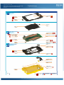
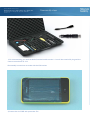
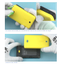
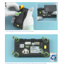
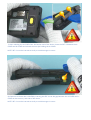
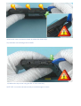
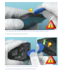
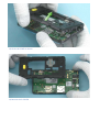
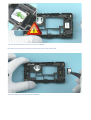
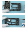
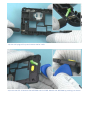
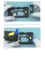
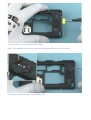
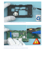
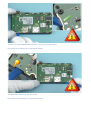
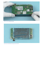
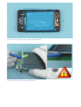
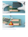
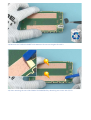
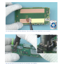
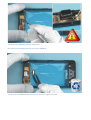
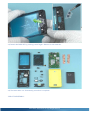
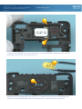
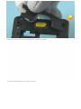
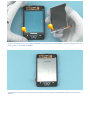
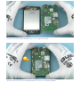
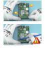
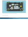
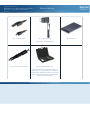
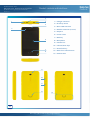
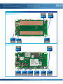
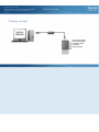
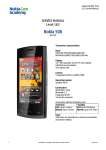
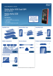
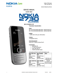
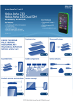
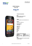
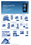
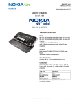
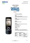
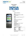
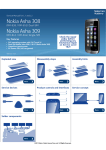
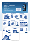
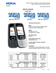
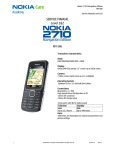
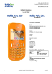
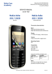
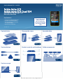
Service Manual for L1 and L2
Nokia Asha 501
Nokia Asha 501 Dual SIM
RM-899, RM-900 (Single SIM)
RM-902 (Dual SIM)
Key features
z
z
z
z
z
Check the repair
policy before
performing any
mechanical repair
on Service Level
1&2!
Totally new Asha Platform OS
Fastlane with Swipe Motion
Social and always connected
3.0" QVGA display
Capacitive touch panel
Version 1.0
Exploded view
Disassembly steps
More
Service devices
Assembly hints
More
Product controls and interfaces
More
More
Service concept
More
©2013 Nokia | Nokia Internal Use only | All Rights Reserved.
More
Solder components
More
Service Manual Level 1 and 2
Nokia Asha 501, Nokia Asha 501 Dual SIM
RM-899 RM-900 (Single SIM), RM-902 (Dual SIM)
Version 1.0
1
Exploded view
A-COVER AND TOUCH ASSEMBLY
(I0001 - I0003)
TOUCH PANEL
I0002
A-COVER
I0001
EARPIECE
I0003
BACK KEY
I0004
DISPLAY
I0013
2
LIGHT SWAP PACKAGE
(I0005 - I0012)
FEM SHIELDING LID
I0009
BB SHIELDING LID
I0008
LCD CONDUCTIVE ADHESIVE
I0011
TOUCH IC GASKET
I0006
LIGHT SWAP PWB
I0007
3
TYPE LABEL
I0012
WLAN SHIELDING LID
I0010
CAMERA
I0005
IHF SPEAKER
I0014
D-COVER ASSEMBLY
(I0014 - I0018)
SPEAKER GASKET
I0015
D-COVER
I0018
DC JACK
I0017
SPEAKER MESH
I0016
ANTENNA MODULE
I0019
RELEASE BUTTON
I0020
SCREW TORX+
SIZE 6 RF 1.6 x 5.0
I0021
B-COVER
I0022
v1.0
Only available
as assembly
©2013 Nokia | Nokia Internal Use only | All Rights Reserved.
Not reuseable
after removal
Repair/swap
only in level 3
Service Manual Level 1 and 2
Nokia Asha 501, Nokia Asha 501 Dual SIM
RM-899 RM-900 (Single SIM), RM-902 (Dual SIM)
Version 1.0
Disassembly steps
1) For disassembling you need the Nokia Standard toolkit version 2. You will also need a DC plug and the
camera removal tool SS-276.
Disassembly instructions are made with dual SIM variant.
2) Protect the A-COVER with protective film.
3) To detach the B-COVER press the RELEASE BUTTON and then pull the B-COVER with fingers.
4) Remove the B-COVER.
5) Use the finger notch to pull out and remove the battery.
6) Unscrew the four Torx+ size 6 screws in the order shown. Do not use them again.
7) Start releasing the A-COVER from the bottom end of the device. Insert the SRT-6 between the ACOVER and D-COVER and release the two clips holding the A-COVER.
NOTE: SRT-6 must be inserted vertically to avoid damages in covers.
8) Continue to release the A-COVER by inserting the SRT-6 into the gap between the A-COVER and DCOVER on the memory card side of the device.
NOTE: SRT-6 must be inserted vertically to avoid damages in covers.
9) Pull the D-cover to direction shown to release the shown clips.
Pay attention not to damage the A-COVER.
10) Release the top corner using the SRT-6 in the same way.
NOTE: SRT-6 must be inserted vertically to avoid damages in covers.
11) To release the top end insert the SRT-6 into to the gap between USB and D-COVER.
Be careful not to damage the USB connector.
12) Lift the D-COVER upwards to release the clip next to the USB.
Pay attention not to damage the covers or the USB connector.
13) Lift the D-COVER as shown.
14) Remove the D-COVER.
15) Use the dental tool to lever out the IHF SPEAKER.
Be careful not to injure yourself with the sharp end of the dental tool.
16) Use tweezers to remove the IHF SPEAKER.
17) Use the dental tool to detach the SPEAKER GASKET.
18) Use tweezers to remove the SPEAKER GASKET. Do not use it again. Discard it.
19) Use a DC plug to lift up and remove the DC JACK.
20) Insert the SRT-6 between the ANTENNA and D-COVER. Release the ANTENNA by pushing it as shown.
21) Remove the ANTENNA.
NOTE: The adhesive tapes are reusable and should stay on the D-COVER. If the adhesive tapes remain on
the ANTENNA, peel them off and place onto the D-COVER.
22) Use the SRT-6 to lever out the RELEASE BUTTON.
23) Use tweezers to remove the RELEASE BUTTON.
NOTE: Once the RELEASE BUTTON is removed the SPEAKER MESH has to be renewed also.
24) Use the dental tool to detach the SPEAKER MESH.
25) Remove the SPEAKER MESH with tweezers. Do not reuse it.
26) Disconnect the DISPLAY connector with the SS-93.
Be careful not to damage the connector or any components nearby.
27) Lever up the ENGINE BOARD with the SS-93 from the shown place.
Be careful not to damage any components nearby.
28) Release the shown clip with the SS-93.
Be careful not to damage any components nearby.
29) Lift up the ENGINE BOARD.
30) Protect the DISPLAY with protective film.
31) Protect also the other side of the A-COVER window.
32) Use SS-93 to carefully lift up the DISPLAY.
33) Separate the DISPLAY.
34) Use the dental tool to detach the TOUCH IC GASKET.
Pay attention not to make any scratches to the ENGINE BOARD.
35) Remove the TOUCH IC GASKET with tweezers. Do not use it again. Discard it.
36) Start removing the two LCD CONDUCTIVE ADHESIVE by detaching one corner with SS-93.
37) Use tweesers to peel off the adhesive. The LCD CONDUCTIVE ADHESIVE is not reusable.
38) Use the camera removal tool SS-276 to detach the CAMERA.
39) Release the EARPIECE with the dental tool.
Be careful not to damage the flex next to the EARPIECE.
40) Remove the EARPIECE with tweezers. Do not use it again. Discard it.
41) Detach the BACK KEY by pushing it with fingers. Remove it with tweezers.
42) The Nokia Asha 501 disassembly procedure is complete.
-END OF DISASSEMBLY-
©2013 Nokia | Nokia Internal Use only | All Rights Reserved.
Service Manual Level 1 and 2
Nokia Asha 501, Nokia Asha 501 Dual SIM
RM-899 RM-900 (Single SIM), RM-902 (Dual SIM)
Version 1.0
Assembly hints
1) Place the IHF SPEAKER into the D-COVER. Make sure the IHF SPEAKER is aligned correctly. The pins
should point towards the cavity with arrow on it.
2) When placing the RELEASE BUTTON make sure it is aligned correctly. Use the D-COVER hole as a
reference. Put the RELEASE BUTTON to its place and press it until you hear the snap sound.
3) Place the shown side of the ANTENNA first into the D-COVER.
4) Fasten the ANTENNA by pressing it as shown.
5) Place the DISPLAY on the A-COVER ASSEMBLY. The driver part of the DISPLAY should be aligned with the
wider gasket on A-COVER ASSEMBLY.
6) Make sure the DISPLAY is fitted to its place and press the edges of the DISPLAY slightly to activate the
adhesive.
7) When placing the ENGINE BOARD make sure it is aligned correctly.
8) Place the shown side of the ENGINE BOARD first into the A-COVER ASSEMBLY.
9) Press the ENGINE BOARD carefully with fingers and check that the clips on both sides are secured.
10) Use the SS-93 to carefully fasten the B2B connector.
11) Fasten the four TORX+ size 6 screws to the torque of 14 Ncm.
-END OF ASSEMBLY HINTS-
©2013 Nokia | Nokia Internal Use only | All Rights Reserved.
Service Manual Level 1 and 2
Nokia Asha 501, Nokia Asha 501 Dual SIM
RM-899 RM-900 (Single SIM), RM-902 (Dual SIM)
Version 1.0
CA-101 Service cable
Service devices
AC-11 Travel charger
AC-8C & CA-190CD for China
SS-276 Camera removal tool
Nokia Standard Toolkit (v2)
For more information, refer to the Service
Bulletin (SB-011) on Nokia Online. Supplier or
manufacturer contacts for tool re-order can be
found in “Recommended service equipment”
document on Nokia Online.
©2013 Nokia | Nokia Internal Use only | All Rights Reserved.
BL-4U Battery
Service Manual Level 1 and 2
Nokia Asha 501, Nokia Asha 501 Dual SIM
RM-899 RM-900 (Single SIM), RM-902 (Dual SIM)
Version 1.0
Product controls and interfaces
3
1
1 — Charger connector
4
2 — Proximity sensor
5
3 — Micro-USB connector
2
4 — Headset connector (3.5mm)
5 — Earpiece
6 — Touch screen
7 — Back key
6
8 — Microphone
9 — Camera lens
10 — Volume/Zoom keys
11 — Power/lock key
7
12 — Back cover release button
8
13 — Antenna area
9
10
11
12
13
v1.0
©2013 Nokia | Nokia Internal Use only | All Rights Reserved.
Service Manual Level 1 and 2
Solder components
Nokia Asha 501, Nokia Asha 501 Dual SIM
RM-899 RM-900 (Single SIM), RM-902 (Dual SIM)
Version 1.0
TOP
GND
Spring
Back
key
X7401
S1004
F3300
X7402
X7403
USB
fuse
GND
Spring
GND
Spring
BOTTOM
Charger
fuse
RF antenna
spring
F2200
J7400
S1000
S1001
Volume/zoom Volume/zoom
+ switch
- switch
S1002
G2250
X1001
J7402
Power/lock
switch
Backup
battery
B2B
connector
RF antenna
GND spring
©2013 Nokia | Confidential | All Rights Reserved.
Service Manual Level 1 and 2
Nokia Asha 501, Nokia Asha 501 Dual SIM
RM-899 RM-900 (Single SIM), RM-902 (Dual SIM)
Version 1.0
Service concept
Flashing concept
Service
software
CA-101
Care Dummy Battery
with power supply
via Nokia charger
or product
specific battery
Transceiver
©2013 Nokia | Nokia Internal Use only | All Rights Reserved.
Service Manual Level 1 and 2
Nokia Asha 501, Nokia Asha 501 Dual SIM
RM-899 RM-900 (Single SIM), RM-902 (Dual SIM)
Version 1.0
Version history
Version
Date
Description
1.0
27.05.2013
First published version
©2013 Nokia | Nokia Internal Use only | All Rights Reserved.