1
Ritter Contact D720
Dental Work Place
- Operating Instructions
- Maintenance Instructions
- Mounting Instructions
J-1136EN, V.02.02.03
Ritter Concept GmbH
Bahnhofstraße 65, 08297 Zwönitz
Fon: 037754/13-0, Fax: 037754/13-342
e-mail: [email protected]
Internet: http://www.ritterconcept.de
Contact D720
Foreword
Dear User,
Congratulations for choosing your new Ritter
equipment and thank you very much for your
confidence!
This modern equipment was produced to the
highest standards by our development and
production engineers.
You and your staff will get real benefit and advantages out of your new Ritter equipment when you
adhere to the technical and operating instructions given during the demonstration while the
equipment was put into operation at your
surgery.
During daily practice, one or the other question
may arise which will be answered by our operating instructions.
For easy operating, consideration of technical
aspects and legal regulations and observation of
the maintenance instructions, we recommend
that you and your staff study this manual very
carefully.
In case of technical problems - call our service
hotline phone 00 49 (0)37754 / 13-290.
And now enjoy your Ritter equipment!
J-1136EN, V.02.02.03
3
Table of Contents
Contact D720
Technical Data
6
Table of dimensions
7
General instructions
8
OPERATING INSTRUCTIONS Dentist's Unit
Table of content
13
Description
15
Order of instruments, instrumentation
16
Operation, burr change
17
Control elements
18
Control elements, foot panel
20
Control elements, 4-pedal foot controller
21
Programming the instruments
22
Instruments, Special functions of the foot panel
23
Air turbine
24
Micromotor
25
Ultrasonic scaler: ZEG
27
Topjet six-function syringe
29
Electro-surgical unit: Elektrotom 190
30
X-ray viewer
32
Dental operating light
33
MAINTENANCE INSTRUCTIONS
Contents
67
Daily
69
Weekly
73
Quarterly
75
Cleaning
84
Failure codes
85
MOUNTING INSTRUCTIONS
Contents
89
Transport of the unit column
91
Transport of the patient chair
92
Mounting
93
How to open the unit column
94
Mounting plan Contact D720
95
Mounting of the instrument carrier
97
Installation plan
99
Valve block
101
Air and water plan (WES D628)
103
Air and water plan Contact
105
Wiring diagram
107
OPERATING INSTRUCTIONS Patient Chair
Contents
37
Description
39
Working Area
40
Operation
41
Control elements, manual control
42
Program control, programming the chair positions
43
Safety stops
44
Head supports, handgrip
45
OPERATING INSTRUCTIONS Assistant's Unit
Contents
49
Description
51
Working area
52
Control elements
53
Cup filling
54
Bowl flush
55
Saliva ejector, surgical suction
56
Suction handpiece
57
Topjet six-function syringe
58
Curing light: Lysta
59
Hydrocolloid quick connection
60
Hygiene System H1
61
Amalgam Separator MST 1
62
Water Disinfection System WES D628
63
Valve for bowl rinse
64
J-1136EN, V.02.02.03
5
Technical Data
Contact D720
Dental work place
Explanations to type plates
Type:
Contact D720
Rated voltage:
230 V~/50 Hz
Rated input:
2300 VA
Mode of operation:
DAB*
Product category:
BF
Protection class:
I
Attention,
See accompanying documents
Non-ionizing
electromagnetic radiation
IPX1
* DAB = continuous operation with intermittent load. The permissible
load times are adapted to the working mode of the dentist (please refer
also to the instructions for the individual units and/or instruments).
Fuse in installation:
16 A time-lag
(e.g. line switch with B-characteristic)
Water pressure:
3,5 ... 5 bar**
Air pressure:
5,5 ... 7 bar
(in case of higher pressures, install a pressure reducer)
Max. water consumption:
Dentist's unit:
Assistant's unit:
Closed equipment
Protected against spilling water (foot controller)
0,15 l/min
4 l/min
** At site there has to be a back-flush protective filter (mesh size 80 - 120
mm) for the water inlet pipe to the supply unit.
*** Addition of stabilized H2O2 with a concentration of 35 - 50 mg/l to
any water coming into contact with the patient.
Interference immunity
Amalgam separator
Interference immunity limit: 3 V/m , complies with regulations
Type:
Metasys, Multi System Type 1
Efficiency of separation:
min. 95 %
Max. water flow:
4,5 l/min
Certification:
PA-II 3816
(Institut für Bautechnik, Berlin, 27.11.89)
Interference frequency
according to EN 60601-1-2 resp. EN 55011 type B; for operation in residential areas or nets which are directly connected with the low voltage net
of the power supply company.
CE-Approval
Water disinfection system
Type:
Disinfection means:
Min. water pressure:
Max. water pressure:
Max. water flow:
according to standard 93/42/EEC for medical products
WES D628
H2O2***
1 bar
5 bar
1,5 l/min
X-ray viewer
Type:
D558
Rated voltage:
230V~/50 Hz
Rated input:
35 VA
Mode of operation:
DB****
Product category:
B
Protection Class:
II
Dental operating light
Type:
D428U
Rated voltage:
230V~/50 Hz
Rated input:
130VA
Mode of operation:
DB****
Product category:
B
These units are not to be operated in areas with risks of
explosion.
Technical modifications reserved.
6
J-1136EN, V.02.02.03
Table of dimensions
Contact D720
The dental work place Contact D720 enables
the dentist to work either sitting or standing.
Dimensions not shown in correct scale.
Swivel arm and flexarm have a large working
radius and can easily be brought into any
desired position.
Dimensions not shown in correct scale.
J-1136EN, V.02.02.03
7
General instructions
Contact D720
0366
Our equipment complies to the safety standards for medical products
(MPG) resp. the regulation 93/42/EEC for medical products.It also
complies to the VDE-requirements for electromedical devices DIN IEC
601, part 1 / DIN VDE 0750, part 1.It is suited for connection to supply
lines installed according to the VDE 0107 regulations for medically used
rooms.
We can only accept responsibility for the safety properties of our equipment, if installation, maintenance, repair and modifications are carried out
by our workshop or by a person explixitly authorized by us. Further, the
equipment has to be correctly handled according to our operating
instructions.
In case of failure, structural parts effecting the security of the device are to
be replaced by original parts only.
In case of repair, the technician must issue a certificate as to the kind and
extent of work performed and, if applicable, indicate any changes of
nominal data and operating range.The certificate must contain the date of
repair, the name of the executing company and a signature (according to
MPG, DIN VDE 0750 / DIN VDE 0751).
Close to the equipment do not operate any apparatus producing electromagnetic emissions (such as wireless phones, micro-wave therapeutics
devices,...).
The unit can be sold with or without HF electro-surgical unit. The special
obligations resulting from the classification have to be adherred to, i.e. the
user is obliged to perform technical. A the stock book (MPG § 22 and
MPBetreibV §§ 5 ... 9.
The safety standards for medical products (MPG) and all legal obligations
are to be fully observed by the user.
Scope and schedules of safety-relevant inspections according to § 6 of
MPBetreibV 29.06.98 are as follows:
At least once a year the following safety-relevant inspections according to
DIN VDE 0750 and DIN VDE 0751 have to be performed.
Visual inspection of equipment and accessories,inspection of ground
conductor according to DIN VDE 0751,measurement of leakage current
according to DIN VDE 0751,performance test of the equipment giving due
regard to the accompanying documents.
We recommend to keep an equipment control log for documenting the
results of the safety-relevant inspections.
Please do not forget to return us the guarantee card within 15 days after
installation of the unit.
According to law, electric equipment is to be disposed by authorized
disposal firms only.
Ritter Concept GmbH
Bahnhofstraße 65, 08297 Zwönitz
In case of maintenance work or trouble
shooting - Caution!
Cut-off power supply first!
8
Fon: 037754/13-0, Fax: 037754/13-342
e-mail: [email protected]
Internet: http://www.ritterconcept.de
J-1136EN, V.02.02.03
Contact D720
J-1136EN, V.02.02.03
Notes
9
Notes
10
Contact D720
J-1136EN, V.02.02.03
Ritter Contact D720
Dental unit
Operating instructions
Ritter Concept GmbH
Bahnhofstraße 65, 08297 Zwönitz
Fon: 037754/13-0, Fax: 037754/13-342
e-mail: [email protected]
Internet: http://www.ritterconcept.de
Contact D720, Dentist's unit
J-1136EN, V.02.02.03
Table of content
Table of content
13
Description
15
Order of instruments, instrumentation
16
Operation, burr change
17
Control elements
18
Control elements, foot panel
20
Control elements, 4-pedal foot controller
21
Programming the instruments
22
Instruments, Special functions of the foot panel
23
Air turbine
24
Micromotor
25
Ultrasonic scaler: ZEG
27
Topjet six-function syringe
29
Electro-surgical unit: Elektrotom 190
30
X-ray viewer
32
Dental operating light
33
13
Description
Contact D720, Dentist's Unit
We recommend you to read this service manual
very carefully in order to have full knowledge of
all the advantages this dental work place is offering you.
Contact D720, Dentist's Unit
Dentist's unit with free hanging instrument
Hoses. Instrument section on flexarm. Supply
unit integrated in pedestal of supporting
column. Unit-mounting of dental operation light
Starlite D 428 as well as of X-ray viewer possible.
Optionally, the dental work place can be
equipped with the water disinfection system
WES D 628.
The main characteristics are:
• Compact configuration, little space
requirement.
• Practice-adapted instrumentation with instruments on different levels
• Illumination for 3 burr instruments.
• Motor control with firm tractive power in
every speed range. Setting for torque limitation.
• Reverse suction-free spray supply to all burr
instruments.
• Clear indicator fields showing the set functions.
• Programming of the functions and of the set
values on different levels (Standard program,
Alternative programs).
• Blocking of each chair function when any
instrument is in operation.
• Integrated digital clock with STOP function
for curing light.
• Single combined foot panel for dentist's unit
and patient chair.
• Control elements for patient chair and assistant's unit.
• Instrument hoses with hose couplings. Water
disinfection with very precise dosage. Safety
for patient and equipment.
• Easy to move swivel arm (precision needle
bearing) with pneumatic brakes.
• Small X-ray viewer integrated in control
panel.
• Wear-resistant switch elements, pressure
transducer technique.
• Integrated double tray.
• New design hinge connection, easy to clean.
• Varnished surfaces, easy to clean.
• Functional design, practice-oriented.
• Optionally, the Contact D720 can be
equipped either with 4-pedal foot controller
or pilot foot switch.
Technical modifications reserved.
J-1136EN, V.02.02.03
15
Order of instruments, instrumentation
Contact D720,Dentist's unit
Order of instruments
The order of the instruments is ergonomical and
adapted to the practice when working with
hanging instrument hoses.
Instrumentation (example)
The instrumentation on the right shows a unit
equipped with 5 instruments:
illuminated turbine
illuminated micromotor
illuminated micromotor
Piezon scaler (optionally with light)
Topjet six-function syringe
16
J-1136EN, V.02.02.03
Contact D720,Dentist's unit
Operation, burr change
Operation
1) in
The unit is activated via the main switch (1
the patient chair pedestal. The main switch pilot
2) in the control
light and the LED indicator (2
panel are then illuminated.
12 : 00 : 00
2
Only the instrument taken from its holder is
ready for operation. All the other instruments
except for the syringe - are locked.
Every day before the first treatment, hold each
instrument over a basin for 30 seconds to
remove water residues.
IImp
portant:: For safety reasons, shut-off the main
switch when leaving the surgery.
Burr change by the assistant
During a pause in treatment: Do not actuate the
foot panel during the burr change to avoid the
hazard of injuries.
During treatment:The assistant can take a
second instrument from its holder for burr or
handpiece change without any danger while
treatment with another first instrument is continued.
1
J-1136EN, V.02.02.03
17
Control elements
Contact D720, Dentist's Unit
UnitMain switch
1 Main switch at the patient chair or at
connection box ON/OFF
2 LED indicator illuminated:
Unit ON via main switch
12 : 00 : 00
2
9
10
4
18
Starlite D428
3 key, dental operating light ON/OFF
20
21
X-ray viewer
4 X-ray viewer
5 key, X-ray viewer ON/OFF
6 film holder (magnet)
8
6
7
19
3
Patient chair
7
8
9
10
1
11
1
1
12
1
key, patient chair UP/DOWN
ey, backrest UP/DOWN
program key P1,1st treatment position
program key P2, 2nd treatment position
program key, mouth rinse position
program key, exit position
Cuspidor (assistant's unit)
13 key, cup filler
1
14 key, bowl flush
1
15 LED indicator for amalgam separator
1
11
12
13
14
5
17
15
16
Water disinfection system
16 LED indicator for water disinfectant (H2O2)
Bell, door opener
17 key for door opener
22
Time setting
18), all instruments must be in
For time setting (1
their holders:
• press key MEMO (19) (LED indicator must
light up)
20) for setting the hours
• press key MINUS (2
1) for setting the minutes
• press key PLUS ((21
19) (LED indicator must
• press key MEMO ((1
extinguish)
23
The seconds cannot be set.
1
18
J-1136EN, V.02.02.03
Contact D720, Dentist's Unit
Control elements
18) will indicate different information:
The display (1
• time (when all instruments are parked)- the
instrument removed from the holder
(T1 = turbine 1, M1 = micromotor 1,
ZEG = scaler, SP = syringe,
ECH = electro-surgical handpiece).
• The preselected speed or torque limitation of
the micromotor, intensity of the electro
surgical unit or of the scaler, syringe heating
ON. This information appears only then when
the instrument is taken from its holder.
M1 40000
18
20
21
19
31
28
24
29
30
19 program preparation key (MEMO)
1
20,21 key for setting speed, torque limitation and
intensity (also syringe heating).
24 Key, torque limitation of micromotor ON/OFF.
25 Program change-over key for instruments.
Instrument light:
33
32
26
27
25
26 Key, instrument light ON/OFF
LED indicator illuminated:
instrument light ON.
27 Key, intensity of instrument light MEDIUM
LIGHT/MAXIMUM LIGHT
LED indicator illuminated:
instrument light at MAXIMUM LIGHT intensity.
Direction of motor rotation
28 Key, direction of micromotor rotation.
LED indicator illuminated: reverse operation of
micromotor ON.
Spraywater for burr instruments
29 Key, spraywater for burr instruments ON/OFF.
LED indicator illuminated: spraywater for burr
instruments ON.
Chip blower
30 Key, chip blower constantly ON during drilling
operation. LED indicator illuminated: chip
blower ON
Topjet syringe
31 Key, syringe heating ON/OFF. LED indicator
illuminated: syringe heating ON
Ultrasonic scaler:
32 Key, endodontic function (root canal
treatment) ON/OFF. LED indicator illuminated:
endodontic function ON
Attention! The LED indicators of keys (24,
26, 27, 28, 29, 30, 31, 32, 33) are only illuminated when the instrument is taken
from its holder.
J-1136EN, V.02.02.03
9
Control elements, foot panel
Contact D720, Dentist's unit
Foot panel Functions of the different keys
All functions needed during treatment
can be obtained and controlled via the
keys of the foot panel.
All keys have several functions - except
for the keys
and
.Which one of
the functions is activated depends on
whether you are in the chair and instrument operation or in the Ritter IBW software operation. Further details are
outlined in the corrresponding sections
of this operating instruction.
Symbols
n
The indicated function is obtained by
one short pressure of the key
nn
The indicated function is obtained by
twice shortly pressing the key
nnn
The indicated function is obtained by
longer pressure > 1 second of the
key
Change of direction of micromotor
rotation normal / reverse rotation
Instrument illumination
No function
Automatic movement to rinsing position
Automatic movement to exit position
Activation of the instrument function when
instrument is out of holder Infinetely
variable or preset speed or automatic
movement to exit position when all
instruments are in their holders
Keys
are for chair positioning or
when working with Ritter IBW software:
Keys
are for cursor control of Ritter
IBW software.
P1
Automatic movement to treatment
position P1
Instrument spray
No function
P2
Automatic movement to treatment
position P2
Chipblower ON (as long as key is being
pressed)
No function
20
J-1136EN, V.02.02.03
Contact D720, Dentist's unit
Control elements, 4-pedal foot controller
4-Pedal Foot Controller
Functions of the switches
As an alternative to the standard foot
panel there is the also possibility to have
the4-pedal foot controller.
2
1
5
All important functions needed duringtreatment can be obtained and controlledvia
the foot controller.
Switch functions
1 when motor is taken out of its holder:
change of direction of motor rotation
when Piezon is out of its holder: Endo
function ON / OFF
when Topjet is out of its holder: Syringe
heating ON/OFF
2 when drilling instrument is out of its holder:
chip blower temporarily ON/OFF
1 + 2 when drilling instrument is out of its
holder: instrument light ON/OFF
3 when drilling instrument is out of its holder:
activation of instrument with spray function
when Piezon is out of its holder: activation of
scaling function
4 when drilling instrument is out of its holder:
activation of drilling instrument without spray
function
3
4
when Piezon is out of its holder: activation of
scaling function
3 + 4 when instrument is out of its holder: same
as switch 3
5 foot lever
J-1136EN, V.02.02.03
21
Programming the instruments
Contact D720, Dentist's Unit
Programming the instruments
All integrated functions can be programmed for
each instrument so that they are already preselected when the instrument is taken from its
holder.
Moreover, for each instrument two different
programs can be stored (for two operators, for
example).
• Standard Program:
LCD indicator (18) does not blink.
• Alternative Program:
LCD indicator (18) blinks constantly in onesecond intervals.
• Changing from one program to the other is
performed by pressing program changeover key (25) - whereby all instruments have
to be in their holders.
The functions are stored individually for eachinstrument, which for this purpose must beremoved from its holder.
Example of program storage for micromotor
Alternative Program
• All handpieces must be in their holders.
M1 40000
• Press program change-over key (25) to
change to the Alternative Program (LCD
indicator (18) blinks constantly in onesecond intervals).
• Take handpiece from its holder. Now, press
any of the desired key functions (keys 24,
26,, 27,, 28,, 29 30).
18
20
19
28
1) to
• Press the PLUS or MINUS key (20 or 21
set the speed. Indicated on LCD display
18).
(1
• Program storage is completed by
19) and program
pressingMEMO key (1
change-over key ((25). Extinguishing of the
LED indicator in the MEMO key confirms that
the program has been stored.
For storing the Standard Program, please
proceed in the same way, however, without
19) and program changepressing MEMO key (1
over key ((25)..
24
21
29
30
26
27
25
In case that one or the other of the preselected
functions of an instrument should be changed
or deleted, change over to the alternative
program by pressing program change-over key
(25), take the handpiece from its holder and add
or delete the desired function by briefly pressingthe appropriate function key. These
changes, however, are maintained only until
thenext change-over to the Standard Program
ismade. All programmed functions are still
present and unchanged after the handpiece has
been returned into its holder again.
The instrument Standard Program has
priority,that means, after activating the dentalwork place via the main switch the Standard
Program will automatically be operative.
22
J-1136EN, V.02.02.03
Instruments, Special functions of the foot
panel
Contact D720, Dentist's unit
Functions of the foot panel
111
108
112
135
107
134
107
136
137
(107)
(108)
(111)
(112)
(134)
(135)
(136)
(137)
108
backrest UP/DOWN(
chair UP/DOWN
move to rinsing position
move to exit position
move to exit position
change to program operation
move to treatment position P1
move to treatment position P2
When one instrument is removed from its
holder the keys of the foot panel have the following functions as long as the instrument is
not activated yet:
111
108
112
135
When not operating in the Ritter IBW Software
and when all instruments are in their holders or
when operating in the Ritter IBW Software and
when all instruments are in their holders,
respectively, and the screen indicates
"Programmbedienung nicht aktiv" (program
operation not active), the different keys of the
foot panel have the following functions:
107
134
107
136
137
(107)
(108)
(111)
(112)
(134)
(135)
(136)
(137)
108
backrest UP/DOWN
chair UP/DOWN
move to rinsing position
move to exit position
activation of the instrument function1)
change of rotation direction of motor
or instrument light
spray
chip blower
1)
With respect to the instruments, key (134) can
have the function of a standard key as long as
the function "Konstante Größe" (constant magnitude) is not activated. This means, infenitely
variable regulation when applying pressure to
this key from left to right or vice versa.
Functions of the 4-pedal-foot controller
138
139
When all instruments are in their holders,
the pedals of the foot controller have the following functions:
(140), (141) move to exit position
When one instrument is removed from its
holder and is not yet activated, the pedals
of the foot controller have the following functions:
(138)
change of rotation direction of motor,
endo function, syringe heating
(139)
chip blower (temporarily)
(138) + (139) instrument light
(140)
activation of instrument function with
water
(141)
activation of instrument function
without water
With respect to the instruments, the pedals
(140) and (141) can have the function of standard foot pedals as long as the "Konstante
Größe" (constant magnitude) is not activated.
This means infinitely variable regulation by more
or less pressure applied to the pedals.
As soon as one instrument is activated
via the foot pedals (134, 140 or 141) all
chair movements are blocked.
140
J-1136EN, V.02.02.03
141
23
Air turbine
Contact D720, dentist's unit
Operation
Take the handpiece from its holder.
The turbine is activated via the foot panel (34) or
the foot controller pedals (40, 41).
The turbine speed appears in the LCD display
(18) as 100 % value and cannot be changed.
Turbine light
The turbine light is switched ON (and OFF, resp.)
by key (26) (LED indicator illuminated). The
turbine light extinguishes 5 seconds after taking
the foot from the foot panel / foot controller or
immediately after returning the handpiece into the
holder and illuminates again when taking the
handpiece from its holder and applying pressure
to the foot panel (34) or foot controller pedals (40,
41).
T1 100 %
18
The light intensity can be increased by pressing
key (27) and is confirmed by illumination of the
LED indicator.
There are two degrees of light intensity:
MEDIUM intensity (26)
MAXIMUM intensity (26 + 27)
29
30
26
27
Spraywater
The turbine spraywater is switched on by key (29)
LED indicator illuminates.
Chip blower
For an increased air stream and better chip
removal during the drilling operation, the chip
blower can be switched for continuous operation
by pressing key (30) in the control panel.
Programmable functions
Functions of the turbine: turbine light, spraywater
and continuous chip blower operation are
programmable.
35
36
37
34
Foot panel
34 operation of turbine
35 pressing key twice within half a second,
turbine light ON/OFF
36 key, spray ON/OFF
37 key, chip blower air only
4-Pedal-foot controller
40 operation of turbine with spray
41
1 operation of turbine without spray
40 + 41 operation of turbine with spray
38 +
+ 39 turbine light ON/OFF
39 chip blower
38
39
Delayed function of the chip blower when
activated via the foot panel.
mp
portant:: Please read the turbine manufacturer's
Im
instructions very carefully.
40
24
41
J-1136EN, V.02.02.03
Micromotor
Contact D720, Dentist's Unit
IOperation
Take the handpiece from its holder.
The micromotor is activated via foot panel (34) or
40, 41).
foot controller pedals (4
Speed range
The final speed of the micromotor can be preselected in 24 steps and appears in the LCD display
18), where 40000 stands for the highest and 400
(1
(KL 700 motor = 2000) for the lowest preselectable speed.
M1 40000
With the micromotor taken from its holder and
20) or (2
21), the speed range of this
pressing key (2
micromotor changes and the last indicated value
is being stored.
18
20
21
19
24
34)
Pressure from left to right applied to foot panel (3
40,
or more or less pressure applied to the pedals (4
41
1) of the foot controller continuously changes the
speed from the lowest value up to the preselected
final value.
28
29
The speed range of the drilling instruments can be
extended by using reducing or increasing contraangles.
30
Constant Speed (MF)
The micromotor can be preset for constant speed
as follows:
26
35
• Take the handpiece from its holder and press
20, 21) to set the desired
PLUS or MINUS key (2
speed.
19)
• Press MEMO key (1
28)
• Press reverse operation key (2
• Thus, the constant speed is preset on both
levels (Standard Program and Alternative
Program)
18) will now indicate MF (sign for
• The display (1
constant speed) as well as the value of the
preset constant speed for the instrument.
27
36
37
34
Deleting the preset constant speed is performed
by taking the instrument from its holder and pres19) and reverse
sing once again MEMO key (1
28).
operation key (2
Torque limitation
In order to warrant that the torque of the micromotor does not exceed a certain value, it can be
24).
limited via key (2
38
40
J-1136EN, V.02.02.03
39
The torque can be preselected in 13 steps and
18), where 22 Nmm
appears in the LCD display (1
(KL 700 motor = 25 Nmm) stands for the highest
and 10 Nmm for the lowest preselectable torque.
41
25
Micromotor
Contact D720, Dentist's Unit
When the micromotor is taken from its holder
24), the value of the torque
and pressing key (2
20 or 21
1) and the
can be preselected with keys (2
last indicated value is being stored.
26, 27)
Micromotor light (2
Please refer to turbine light.
Reverse operation of the micromotor
Reverse operation of the micromotor is effected
28). LED indicator illuminates.
by key (2
Spraywater
Spraywater for the micromotor is switched on
29). LED indicator illuminates.
via key (2
Chip blower with continuous operation
For an increased air stream and better chip
removal during the drilling operation, the chip
blower can be switched for continuous opera30) in the control panel.
tion by pressing key (3
Programmable functions
Functions of the micromotor: speed range,
torque limitation, micromotor light, reverse
operation, spraywater and continuous chip
blower operation are programmable.
Foot panel
34 operation of micromotor and speed
regulation
35 pressing key once:
reverse operation of micromotor ON/OFF
pressing key twice (within half a second):
instrument light ON/OFF
36 key, spray ON/OFF
37 key, chip blower, air only
4-Pedal-foot controller
40 operation of micromotor with spray
41
1 operation of micromotor without spray
40 + 41 operation of micromotor with spray
38 + 39 instrument light ON/OFF
38 reverse operation of micromotor ON/OFF
39 Chip blower
mp
portant:: Please read the micromotor manuIm
facturer's instructions very carefully.
26
J-1136EN, V.02.02.03
Ultrasonic scaler: ZEG
Contact D720, Dentist's unit
Technical data:
43
mode of operation:
DAB*
optionally with light
BF
More technical data and operating hints can be
M
found in the operating instructions for the handpiiece which are enclosed!
p
ZEG 100 %
Operation
18
Take the handpiece from its holder.
20
34) or
The scaler is activated via foot panel, key (3
40, 41).
foot controller pedals (4
21
19
*DAB = continuous operation with intermittent
load. The permissible load times are adapted to
the working mode of the dentist.
28
Intensity
The intensity of the scaler can be preselected in
5-percent-steps and appears in the LCD display
18), whereby 100 % stands for the highest and
(1
20 % for the lowest preselectable intensity.
With the handpiece taken from its holder and
20 or 21), the intensity can be
pressing key (2
changed.
32
26
27
34) of
Pressure from left to right applied to key (3
the foot panel or more or less pressure applied
40, 41) continuously changes
to the foot pedals (4
the speed from the lowest value up to the
preselected final value.
Constant Intensity (ZF)
The ultrasonic scaler can be preset for constant
intensity:
35
• Take the handpiece from its holder and
20, 21) to set the
press PLUS or MINUS key (2
desired intensity.
19)
• Press MEMO key (1
28)
• Press reverse operation key (2
• Thus, the constant intensity is preset on both
levels (Standard Program and Alternative
Program)
18) will now indicate ZF (sign for
• The display (1
constant intensity) as well as the value of the
chosen preset constant intensity.
34
38
39
Deleting the preset constant intensity is
performed by taking the instrument from its
holder and pressing once again MEMO key (19)
28).
and reverse operation key (2
Endo Function
The endodontic function (root canal treatment)
32). LED indicator illumiis activated by key (3
nates.
Water regulation
For water regulation, the scaler Piezon PZ is
33) on the handprovided with a knurled nut (3
piece.
40
J-1136EN, V.02.02.03
41
27
Ultrasonic scaler: ZEG
Contact D720, Dentist's Unit
Handpiece light (26, 27)
visit to turbine light
Programmable functions
Functions of the scaler: intensity and Endo
function are programmable.
Foot panel
34 Operation of the scaler and intensity
regulation.
35 pressing key twice within half a second,
handpiece light ON/OFF
4-Pedal foot controller
40 or/and 41 operation of the scaler
38 Endo function ON/OFF
38 + 39 handpiece light ON/OFF
Important: Please read the manufacturer's
instructions for the ultrasonic scaler very
carefully.
28
J-1136EN, V.02.02.03
Topjet six-function syringe
Contact D720, Dentist's unit
Main characteristics
46
47
44
The Topjet syringe is very handy. Due to its
design, it allows good access to all jaw
quadrants. The syringe tip (39) is rotatable.
Operation
45
Water, air or spray are controlled manually
Supply of the media lasts as long as the corre47) is epressed. Either
sponding key of handle (4
45) or water (46) can be obtained by actuaair (4
ting the corresponding key. Actuating both keys
45 + 46) at the same time will supply spray.
(4
31
1), warm air,
After switching on the heating (3
warm water or warm spray are available.
Syringe heating (20 % - 100 %)
18) indicates syring heating
The LCD display (1
ON/OFF. The temperature of the syringe heating
18) indicates
can be set in 5 steps. The display (1
the following signs:
SP kalt
18
20
31
21
•
•
•
•
•
- - - +/++
+++
Whereby the last step indicates the highest
possible temperature of the media (air, water,
spray).
Volume
The volume of air, water and spray depends on
the force applied to the keys during operation.
Programmable functions
Heating ON and temperature degree.
Notes:
After activating the dentist's unit (for example in
the morning), the syringe heating is always OFF.
4-Pedal foot controller
38 syringe heating ON/OFF.
38
J-1136EN, V.02.02.03
29
Electro-surgical unit: Elektrotom 190
Contact D720, Dentist's unit
Technical Data
supply voltage:
33V DC
rated input:
75 VA
rated frequency:
500 kHz ± 10 %
max. HF-rated capacity:
50 W / 400 W
mode of operation:
DAB(ED=25 %)*
ECH 100 %
Operation
18
Take the handpiece from its holder. The electro34)
surgical handpiece is activated via the key (3
40, 41) of the foot
of the foot panel or pedal (4
controller.
*DAB = continuous operation with intermittent
load. In case of an operation of 25 % this corresponds for instance 6 sec. OPERATING TIME 15 sec. PAUSE.
20
19
21
28
Intensity
The intensity of the electro-surgical unit can be
preselected in 5-percent-steps and appears in
18), whereby 100 % stands for
the LCD display (1
the highest and 20 % for the lowest preselectable intensity.
33
With the handpiece taken from its holder and
20 or 21), the intensity can be
pressing key (2
changed. Pressure from left to right applied to
34) of the foot panel or more or less preskey (3
40, 41
1) of the 4-pedal foot
sure to pedals (4
controller continuously changes the speed from
the lowest value up to the preselected final
value.
Constant Intensity
The electro-surgical unit can be preset for
constant intensity:
• Take the handpiece from its holder and
20, 21) to set
press PLUS or MINUS key (2
the desired intensity.
19)
• Press MEMO key (1
28)
• Press reverse operation key (2
• Thus, the constant intensity is preset on both
levels (Standard Program and Alternative
Program).
18) now indicates EF sign for
• The display (1
contant intensity) as well as the value of the
chosen preset contant intensity.
34
Deleting the preset constant intensity is
performed by taking the instrument from its
19)
holder and pressing once again MEMO key (1
28).
and reverse operation key (2
Automatic operation
For automatic operation of the electro-surgical
33). LED indicator illuminated.
unit press key (3
40
30
41
J-1136EN, V.02.02.03
Contact D720, Dentist's unit
Electro-surgical unit: Elektrotom 190
Operating hints
The high frequency electro-surgical unit Elektrotom 190 is for operation without neutral electrode.
In order to prevent burs, special attention has to
be paid that there is not contact between patient
and power activated metal parts of the patient
chair. It may be possible that heat is generated
in such areas. Therefore, the patient is to be
advised to put his hands on his lap.
A visual inspection of the accessories and the
ahndpiece with instrument hose must be
performed very frequently in order to detect
early any defects and to have them repaired by
a service technician.
Attentiion: It is possible that during operating the
hifh frequency electro-surgical unit the functions
of other electronic equipment is interfered.
Cardiac Pacemaker
Special attention has to be paid during treatment of patients with a cardiac pacemaker. Due
to the high freequency current the cardiac pacemaker can be irritated and cause arhythms.
Programmable functions
Programmable functions of the electro-surgical
unit: intensity and automatic operation.
Foot panel
34 operation of the electro-surgical unit and
intensity regulation.
4-Pedal foot controller
40 and/or 41 operation of the electro-surgical
unit and intensity regulation.
External electro-surgical unit
In case of an external electro-surgical unit, the
functions of the dental unit have to be set out of
33) blocks any actions
order. Pressing the key (3
33) once
of the dental work place. Pressing key (3
more, will release the blockade.
IImp
portant: Please read the manufacturer's
instructions very carefully.
J-1136EN, V.02.02.03
31
X-ray viewer
Contact D720, Dentist's unit
Optionally, the dentist's unit can be equipped
50).
with X-ray viewer D558 (5
The X-ray viewer has an illuminated panoramic
screen of 29 cm x 12.5 cm and is mounted to
51
1).
the carrier arm of the tray table (5
53
Main Characteristics
• horizontally movable by 90 º.
• uniform illumination of the screen with a
powerful light of 12,000 Lux
• the screen is inclined by 15 o which allows
optimum posture and best vision for the
operator.
• easy to clean due to its rounded shape.
54
50
52
Control elements
52 screen
53 film holder
54 switch
Operation
54) ON/OFF when the dental work place
Switch (5
is switched ON.
51
32
J-1136EN, V.02.02.03
Contact D720,Dentist's unit
Dental operating light
Optionally, the dental working place can be
equipped with a dental operating light Starlite
55).
D428U (5
Operating light with facet reflector (and 24 V /
150 W halogen bulb) on flexarm mounted to
assistant's unit.
The main characteristics are:
• powerful light with shadow reduction
• easy to position does not drift out of position
• removable handles
Operation elements
56 lever switch
57 dimmer
58 key for operating light at dentist's and/or
assistant's control panel
59 handle
Operation
When the dental working place is switched ON
the operating light can be switched ON and
56) or key (5
58).
OFF either via lever switch (5
55
58
Attentiion!! The operating light illuminates only
56) and (5
58) are in ON
than when both switches (5
position. For switching OFF the operating light
operation of only one switch is sufficient.
Light intensity
The desired light intensity from 8,000 up to
22,000 Lux can be infinitely varied by turning the
57). The illuminated field is 10 x 20 cm
dimmer (5
(illuminated field and intensity are measured at a
distance of 80 cm to the reflector).
56
57
59
J-1136EN, V.02.02.03
33
Notes
34
Contact D720, Dentist's unit
J-1136EN, V.02.02.03
Ritter Contact D720
Dental patient chair
- Operating instructions
Ritter Concept GmbH
Bahnhofstraße 65, 08297 Zwönitz
Fon: 037754/13-0, Fax: 037754/13-342
e-mail: [email protected]
Internet: http://www.ritterconcept.de
Contact D720, Patient Chair
J-1136EN, V.02.02.03
Contents
Contents
37
Description
39
Working Area
40
Operation
41
Control elements, manual control
42
Program control, programming the chair positions
43
Safety stops
44
Head supports, handgrip
45
37
Contact D720, Patient Chair
Description
We recommend you to read this service manual
very carefully in order to have full knowledge of
all the advantages this chair is offering you.
Contact D720, Patient Chair
Free programmable motor chair for dentists and
orthodontists.
The main characteristics are:
• quickset programming for four chair
positions
• maintenance-free spindle motors, very
reliable and extremely quiet
• great height adjustment for working in sitting
or standing position
• large adjustment range of backrest for
reclined and upright backrest position
• backrest with integrated arm support
• slim backrest for more leg room
• comfortable seat portion, soft and anatomically shaped
• small, round head support, enables the
dentist to get even closer to the patient
(standard type).
As an option: Longish head support and
children's head wedge.
• large adjustment angle of head support for
easier treatment of upper and lower jaw
• recessed backrest portion for head support
to allow better support of small patients
• handgrip for patient
• operation of patient chair either manually via
dentist's unit and assistant's unit or via the
foot panel or the optional pilot foot switch
• safety stops, in order to avoid the hazards of
injury, especially during programmed operations
Technical modifications reserved.
J-1136EN, V.02.02.03
39
Working Area
Contact D720, Patient Chair
The patient chair allows the dentist to work
either sitting or standing.
Differentiated movement between backrest
inclination and seat inclination, mechanically
coupled.
S highest backrest position
M medium backrest position
M
T lowest backrest position
Dimensions of patient chair
40
J-1136EN, V.02.02.03
Contact D720, Patient Chair
Operation
Operation
1) in
The chair is activated via the main switch (1
the chair pedestal. In ON-position, the main
2) in the
switch pilot lamp and the LED indicator (2
control panel illuminate.
12 : 00 : 00
2
IImp
portant:: For safety reasons, shut-off the main
switch in the chair pedestal when leaving the
surgery.
1
J-1136EN, V.02.02.03
41
Control elements, manual control
Contact D720, Patient Chair
Control elements
The patient chair can be controlled from the
dentist's side (control panel of dentist's unit),
from the assistant's side (control panel of assistant's unit) and via the foot panel or pilot foot
switch.
12 : 00 : 00
IImp
portant:: The patient chair is blocked in all its
functions even if pressure is applied to foot
panel or pilot foot switch when any of the handpieces is taken from the instrument holder
(except for the syringe).
8
7
Manual control
The patient chair is controlled manually by keys
7, 8) and can be brought into any desired posi(7
tion.
The arrows on the keys indicate the direction of
the chair movement.
The patient chair can also be controlled via the
39/4
40).
foot panel keys (3
If the patient chair is equipped with a pilot foot
switch it can be positioned via the foot lever
41
1). Moving the lever to the right or left, respec(4
tively, effects up or down movement of the
backrest. Moving the lever up or down, respectively,effects up or down movement of the chair.
7
8
40
39
39
34
40
41
42
J-1136EN, V.02.02.03
Contact D720, Patient Chair
Program control, programming the chair
positions
Program control
12 : 00 : 00 9
10
The patient chair is provided with 4 programs,
i.e., 4 different chair positions can be stored and
called automatically.
12
9) or (1
13) twice or
• treatment position P1, key (9
36) or (4
42)
(3
10) or (1
14) twice
• treatment position P2, key (1
37) or (4
42) twice
or (3
11
1) or (1
13) or (3
38)
• mouth rinse position, key (1
43). When pressing again one of these
or (4
keys, the patient chair returns to its last treatment position.
12) or (1
14) or
• Exit position, press twice key (1
38) or (4
43) twice
(3
19
11
The chair moves also to exit position when
34) or pedal (4
44),
briefly pressing foot panel (3
however, only when all instruments are in their
holders.
IImp
portant:: Any automatic movement will be
interrupted immediately when any one of the
keys is pressed.
Programming the chair positions
Storing of the automatic chair positions via the
control panel of the dentist's unit.
Please proceed as follows:
13
• Bring the patient chair manually into the
desired position.
19). LED indicator illumi• Press MEMO key (1
nates.
9,, 1
10,,
• Press one of the four program keys (9
11
1
1,, 1
12). Extinguishing of the MEMO key LED
indicator confirms storage of the program.
Storing of the automatic chair positions via
the control panel of the assistant's unit.
14
15
Please proceed as follows:
• Bring the patient chair manually into the
desired position.
15) and hold depressed.• Press MEMO key (1
13,, 1
14) is
Now, one of the two program keys (1
being pressed once or twice, respectively,
after that, stop all pressure on keys.
38
The so stored program can now be called by
pressing the appropriate key.
36
37
34
The stored programs P1 and P2 can also be
36) and (3
37)
called via the foot panel keys (3
however, only when all instruments are in their
holders (keys with double function).
42
43
44
J-1136EN, V.02.02.03
44
43
Safety stops
Contact D720, Patient chair
Safety stops
SIS 5
SIS 6
In order to avoid the hazard of injuries, backrest
SIIS 1
1), rear side of the seat (S
SIIS 2) as well as
(S
SIIS 4) are so designed that
the yoke housing (S
upon interference their downward movement
stops and reverses into an upward movement of
approx. 30 ... 40 mm.
SIIS 3)
The back end plate of the chair pedestal (S
too is provided with microswitches to stop the
downward chair movement when acidentally
placing the foot on it.
SIIS 5) of the assistant's
The instrument holder (S
unit also reacts to chair contact by stopping the
chair movement.
A safety stop in the hinged arm of the assistant's
SIIS 6) will stop the chair upward movment,
unit (S
if the arm is accidentally swivelled too far into
chair direction.
SIS 1
SIS 4
SIS 3
44
SIS 2
J-1136EN, V.02.02.03
Contact D720, Patient Chair
Head supports, handgrip
Head support
50
Extension and tilting of the head support can
be easily performed with one hand only. The
height adjustment of the head support is infinitely variable (self-locking). The extension length
is approx. 15 cm.
50) has to
For tilting backwards, locking device (5
be released by pulling.Tilting forwards can be
performed without pulling the locking device.
The head support can be taken off and inserted
again without problems.
Illustration on the left:
Longish head support
Illustration on the right:
Standard head support and children's head
wedge
Handgrip
51
J-1136EN, V.02.02.03
51
1) supports the patient when
The handgrip (5
mouth rinsing.
45
Notes
46
Contact D720, Patient chair
J-1136EN, V.02.02.03
Ritter Contact D720
Assistant's Unit
Operating instructions
Ritter Concept GmbH
Bahnhofstraße 65, 08297 Zwönitz
Fon: 037754/13-0, Fax: 037754/13-342
e-mail: [email protected]
Internet: http://www.ritterconcept.de
Contact D720, Assistant's unit
J-1136EN, V.02.02.03
Contents
Contents
49
Description
51
Working area
52
Control elements
53
Cup filling
54
Bowl flush
55
Saliva ejector, surgical suction
56
Suction handpiece
57
Topjet six-function syringe
58
Curing light: Lysta
59
Hydrocolloid quick connection
60
Hygiene System H1
61
Amalgam Separator MST 1
62
Water Disinfection System WES D628
63
Valve for bowl rinse
64
49
Description
Contact D720, Assistant's unit
We recommend you to read this service Manual
very carefully in order to have full knowledge of
all the advantages this assistant's unit is offering
you.
Contact D720 Assistant's Unit
Cuspidor fully integrated in unit column.Instruments on swivel arm.Optionally, hygiene system
H1 for permanent decontamination and disinfection of suction hoses.Built-in amalgam separator
(as an option).
The main characteristics are:
• Ceramic cuspidor bowl, with a fastness of
colour and scratch resistance
• Cuspidor bowl plugged in easy to remove
for cleaning
• Simple maintenance of amalgam separator,
easily accessible via an opening
• Safety for the patient due to permanent
disinfection of the suction hoses
• Automatic cup filling. Plastic cup is recognized by optical sensors.
• Instrumentation on swivel arm holder with
double articulation with an extreme wide
working radius (enables the dentist to work
without an assistant)
• Tray table for assistant
• Control panel for assistant
• Safety switch in swivel arm
Technical modifications reserved.
J-1136EN, V.02.02.03
51
Working area
Contact D720, Assistant’s unit
The assistant's unit is integrated in the unit
column. No cables or supply hoses on the
floor.
Dimensions are not shown in correct scale.
The double-arm of the assistant's unit has an
extremely wide working radius. Instrument
holder and control panel with tray table can be
brought very close to the patient or swivelled
far off in order to give the assistant space.
Dimensions are not shown in correct scale.
52
J-1136EN, V.02.02.03
Contact D720, Assistant's unit
52
Control elements
53
55
54
56
61
57
62
60
59
56
63
58
12 : 00 : 00
2
3
8
7
11
12
65
66
67
91
13
1 main switch ON/OFF
1
2 LED indicator illuminated: work place ON via
main switch
3 key, dental operating light ON/OFF
7 key, patient chair UP/DOWN
8 key, backrest UP/DOWN
11
1
1 program key, mouth rinsing position, treatment position 1
12 program key, exit position, treatment position
1
2
13 key, cup filler
1
14 key, bowl flush
1
15 amalgam separator, LED indicator blinks
1
slowly (2-second intervals): amalgam
collector is 95 % full LED indicator blinks
quickly (1-second intervals): centrifuge
disturbance
16 water disinfection system LED indicator
1
blinks: water disinfectant H2O2 must be
refilled LED indicator constantly illuminated:
disturbance of water disinfection system
52 cuspidor bowl
53 pipe for bowl flush. The pipe can be taken
off for cleaning the bowl. Before doing so, it
is absolutely necessary to switch off the unit
1) in the patient chair
via the main switch (1
pedestal!
54 cup, not transparent
55 cup filler. Can be taken off for cleaning the
bowl. Before doing so, it is absolutely necessary to switch off the unit via the main switch
1) in the patient chair pedestal!
(1
56
6 swivel arm with double articulation
57
7 tray table
58
8 instrument holder
59
9 saliva ejector
60 spray suction
61
1 syringe
62 curing light
63 control panel, assistant's unit
65 door opener
66 key, syringe heating ON/OFF
67 Memo key
68 hydrocolloid quick-connection optionally,
the assistant's unit can be provided with a
hydrocolloid quick- connection
11) and (1
12) have double functions:PresKeys (1
sing them quickly twice corresponds to
11 treatment position P1
1
12 treatment position P2
1
Attention!
15
16
Switch off the unit at the main switch in the
patient chair pedestal before removing cup filler
and pipe for bowl flush.
68
1
J-1136EN, V.02.02.03
53
Cup filling
Contact D720, Assistant's Unit
Cup filling
To fill the cup, there is a choice of two programs
- either MANUAL AUTOMATIC or SEMI-AUTOMATIC. Factory setting is manual automatic. A
subsequent change can be made by the service
technician.
53
The filling level is dependent on the previous
manual cup filling procedure. Place glass or
plastic cup on the support plate. Press MEMO
19) of dentist's control panel (LED indicator
key (1
13) until the glass
illuminated). Now, press key (1
or plastic cup has reached the desired filling
level. Extinguishing of the MEMO key LED indicator and three beeps confirm that programming of the filling level has been stored.
Alternatively, cup filling level can also be stored
19) and (1
13) of
by simultaneously pressing keys (1
the assistant's unit until the desired filling level
is reached. Recommended filling level: two
thirds of the glass or plastic cup.
55
12 : 00 : 00
Accidential excess water will vanish via the cup
support plate.
MANUAL AUTOMATIC
13) the glass or plastic cup is
By pressing key (1
being filled. The filling procedure stops automatically. Premature stop of filling procedure: press
13) once more.
key (1
19
SEMI-AUTOMATIC
The glass or plastic cup is automatically filled
after placing it onto the support plate (with a
time lag of 3 seconds).
13
14
13
19
14
13) the filling level can be
By pressing key (1
increased.
Factory setting is manual automatic.
A subsequent change can be made by the
service technician.
IImp
portant:: Do not use any transparent glasses.
The water intensity of the cup filler (55) is regu69). Turning the nob
lated with adjustment knob (6
to the left increases and turning the knob to the
right reduces the water intensity, respectively.
This adjustment knob is to be found in the unit
68) which has a magnetic
column, behind door (6
lock.
68
69
54
70
J-1136EN, V.02.02.03
Contact D720, Assistant's unit
Bowl flush
Manual bowl flush
14) and stops
The bowl flush starts when pressing key (1
automatically after approx. 20 seconds.Premature stop
14) once more.
of bowl flush: press key (1
Automatic bowl flush
Automatic bowl flush starts when taking the glass from
the support plate.
The flushing time is constant and set for 20 seconds.
Factory setting is automatic bowl flush, however, this can
subsequently be changed by the service technician.
The flushing intensity of the bowl flush pipe (53) is regu70). Turning the knob to the
lated by adjustment knob (7
left increases and turning the knob to the right reduces
the flushing intensity, respectively. This adjustment knob
68) which
is to be found in the unit column behind door (6
has a magnetic lock.
J-1136EN, V.02.02.03
55
Saliva ejector, surgical suction
Contact D720, Assistant's Unit
Saliva ejector
The handpiece can be equipped with common
71). When taking the saliva ejector
suction tips (7
from its holder, the central aspiration system is
activated.The handpieces which remain in their
instrument holders are shut-off.
9) allow
Design and size of the handpiece (59
easy handling with one hand. With thumb and
72) and tip (7
71) can be turned
forefinger sleeve (7
into the desired position without torsion of the
73).
hose (7
71
72
59
73
Surgical suction
The handpiece can be equipped with common
75).
surgical tips (7
74) from its
When taking the surgical suction (7
holder, the central aspiration system is
activated.
When returning the handpiece into the holder,
the aspiration system is shut-off.
75
74
The handpiece can also be equipped with
common saliva ejector suction tips.
56
J-1136EN, V.02.02.03
Contact D720, Assistant's unit
Suction handpiece
Suction handpiece
The handpiece can be equipped with common
76).
suction tips (7
60) from its
When taking the suction handpiece (6
holder, the central aspiration system is
activated.
77) allows handling with
The rotatable sleeve (7
77)
one hand. With thumb and forefinger sleeve (7
76) can be turned into the desired posiand tip (7
78).
tion without torsion of the hose (7
76
77
60
The suction handpiece can also be equipped
with a surgical tip when using an adaptation
sleeve.
open
close
60
When returning the handpiece into the instrument holder, the aspiration system is shut-off.
J-1136EN, V.02.02.03
57
Topjet six-function syringe
Contact D720, Assistant's Unit
Main characteristics
The Topjet syringe is very handy. Due to its
design, it allows good access to all jaw
quadrants. The syringe tip (44) is rotatable.
46
47
44
Syringe handpiece with disposable tip
Disposable tip with adapter optionally.
Order No. F 317-075 - disposable tip (100
pieces)
45
Order No. F 317-074 - adapter
Operation
Water, air or spray are controlled manually.
Supply of the media lasts as long as the corre7) is depressed. Either
sponding key of handle (47
6) can be obtained by actuaair (45) or water (46
ting the corresponding key. Pressing both keys
+ 46
6) at the same time will provide spray.
(45 +
66) warm air,
After switching on the heating (6
warm water or warm spray are available.
Syringe heating
When switching ON the heating for the assistant's syringe there is one beep to be heard,
when switching OFF - two beeps. The temperature of the syringe media (air, water, spray)
preselected at the dentist's unit applies also for
the assistant's syringe.
66
Volume
The volume of air, water or spray depends on the
force applied to the keys during operation.
Note:
After activating the unit (for example in the
morning), the syringe heating is always OFF.
58
J-1136EN, V.02.02.03
Contact D720, Assistant's unit
Curing light: Lysta
Technical data
81
82
supply voltage:
24 V AC
rated input:
70 W
voltage supply to bulb: 8.9 V DC
mode of operation:
DAB (ED = 50 %)*
62
*DAB = Continuous operation with intermittent
load. In case of an operation of 50 % this corresponds for instance 10 min (24 cycles) OPERATING TIME - 10 min PAUSE
Operation
62) from its holder. The
Take the handpiece (6
18) indicates the number 40. This
display (1
means that the curing light is switched on for 40
82). After 40
seconds after pressing switch (8
seconds, the light beam will extinguish automatically. Four beeps indicate the end of the curing
cycle.
The standard cycle of 40 seconds can be
0, 21
1) before
reduced or increased via keys (20
82). In case of overheating, the
pressing switch (8
lamp is temporarily switched off automatically
via a thermoprotection switch. It is possible to
erform several curing cycles consecutively.
00 :40
18
Operating hints
20
21
Please adhere to the composite material manufacturer's instructions as different materials and
shades have specific curing characteristics. A
precondition for proper curing of the composite
material is that light guide and blue filter are
clean (please refer to "Maintenance"). Clean very
frequently with isopropyl alcohol. Avoid any
contact between the polished end of the light
81
1) and non-cured composite material. If
guide (8
necessary, clean with alcohol. Hold the handpiece in such a way that the vent slots are not
covered by your hand.
62
J-1136EN, V.02.02.03
Do not look directly into the curing beam.
59
Hydrocolloid quick connection
Contact D720, Assistant's unit
83) of the hydrocolloid quick
The plug nipple (8
67) is suited for a ¼" hose which
connection (6
serves as coolant water supply line to the hydrocolloid moulding spoon.
The nipple (in the accessories) is plugged into
the quick connect and secured with the locking
lever in the annular groove of the quick connect
bushing. Prior to connection, assure proper
water discharge of the coolant water discharge
pipe into the cuspidor bowl as the coolant water
supply is released automatically as soon as the
connection is made.
67
IImp
portant!!
As soon as the connection is
made,take assistant's Topjet out of its port and
lay it down. This will prevent that the coolant
water supply is stopped prematurely. This could
happen, because after two minutes the main
valves will shut automatically if they were not
activated during this period of time.
83
60
J-1136EN, V.02.02.03
Contact D720, Assistant's unit
Hygiene System H1
97
93
The hygiene system H1 can be optionally integrated into the assistant's unit. Factory standard
is the suction system S1 for which the following
does not apply.
Function of Hygiene System H1
The hygiene system H1 takes care of cleaning
the suction hoses. It works automatically and
reduces the hazard of infection brought about
by the secretion-carrying tubes. As long as aspiration takes place, the hygiene system takes
care of permanent cleaning and disinfecton of
those parts of the aspiration system which
constantly become contaminated.
IImp
portant:: Please do not use any additional
cleaning or disinfection means as this could
cause negative interactions of the different
chemicals.
Initial cleaning program
96
95
94
Whenever the unit main switch is switched ON,
the aspiration system becomes activated and
the initial cleaning program starts automatically
for approx. 20 seconds (approx. 10 seconds per
suction hose). This means that an increased
dosage of chemicals takes place in order to
remove foam and any residues which may have
detached over night. The suction handpieces
remain in their place, the shut-off valves of the
handp
piieces, however,, must be op
pened. Taking
the suction handpiece from its holder and
working with it will not interfere with the program.
Permanent cleaning ot the suction hoses
Starting at that moment when taking one (or
both) suction instrument from its holder until
placing it back again, contamination is impossible due to permanent water rinsing. The periodical dosage of chemicals disinfects and
removes the foam within the aspiration system.
The ratio chemicals/water can be changed by
the service technician.
Special cleaning program
We recommend to apply the special cleaning
program at least once a day (in the evening) or
after heavy contamination of the aspiration
system (with blood, purulent etc.). The special
cleaning program is activated by pressing key
97) and lasts approx. 3minutes. LED
PUSH (9
96) blinks. The suction handpieces
indicator (9
remain in their place, the shut-off vallve of the
handp
piiece,, however,, must be op
pened..
93)
Control Unit (9
94 LED indicator blinks red (and single beep
whenever a suction handpiece is removed
from its holder): disturbance of the hygiene
system. However, operation still possible.
Call service technician.
95 LED indicator blinks yellow (and single
beep whenever a suction handpiece is
removed from its holder): replacement of the
chemical tank necessary.
96 LED indicator blinks yellow - this indicates
that the special cleaning program is ON
97 PUSH key for activating the special cleaninggram.
J-1136EN, V.02.02.03
61
Amalgam Separator MST 1
Contact D720, Assistant's unit
The optionally integrated amalgam separator
MST 1 helps you to meet all environmental
protection requirements. Contamination of
waste water by amalgam is drastically reduced.
12:00:00
The main characteristics of the amalgam
separator are:
• Two-step separation in short and systemadapted intervals (sedimentation and
centrifugation)
• Integrated dirt-resistant air/water separation
• Self-cleaning centrifuge double chambers
• Degree of amalgam separation: 98.6 %
• Separate processing of the two different
waste streams (aspiration, waste water)
When the amalgam collector is filled by 95 %,
15) blinks slowly (in twothe LED indicator (1
second intervals). Additonally, the dentist's unit
gives 4 signals, each with 4 short beeps
whenever the unit is switched ON and wheneverthe chair moves to the automatic exit position. The collector must be exchanged soon.
However, operation is still possible. When the
amalgam collector is 100 % full, the suction flow
valve does not open any more and thus operation is made impossible.
15) blinks quickly (oneWhen the LED indicator (1
second intervals), there is a centrifuge disturbance and the service technician must be
called.
62
15
J-1136EN, V.02.02.03
Contact D720, Assistant's unit
Water Disinfection System WES D628
16
By means of the optional water disinfection
system WES D 628 the patient water, i.e. instrument spray water and mouth rinsing water, is
being pretreated. The effective substance is
H2O2 with an initial concentration of 3 % which
in the system becomes diluted to a 35 ... 50
mg/l employable solution.
If the tank for the disinfectant H2O2 is almost
16) blinks. The tank
empty, the LED indicator (1
must be refilled with 1 liter of Formatex (Order
No. U 4700).
16) is constantly
If the LED indicator (1
illuminated, the water disinfection system has a
failure and
the service technician must be
called.
In case of failure of the water disinfection
system, the unit is automatically switched over
to normal, non-treated water and operation with
the unit can be continued.
J-1136EN, V.02.02.03
63
Valve for bowl rinse
Contact D720, Assistant's unit
Optionally, the assistant's unit can be provided
with a valve for bowl rinsing. This valve eliminates suction noises at the cuspidor bowl.
In order to warrant proper function of this valve,
the automatic cleaning process has to be
activated at least twice a day.
1) and the control
The valve for bowl rinsing (1
element (2) are integrated in the column of the
assistant's unit.
For activating the automatic cleaning process
press key (3).
1
The manufacturer's instructions have to be
adherred to.
2
3
64
J-1136EN, V.02.02.03
Ritter Contact D720
Dental work place
Maintenance instructions
Ritter Concept GmbH
Bahnhofstraße 65, 08297 Zwönitz
Fon: 037754/13-0, Fax: 037754/13-342
e-mail: [email protected]
Internet: http://www.ritterconcept.de
Contact D720, maintenance
Contents
Contents
67
Daily
69
Weekly
73
Quarterly
75
Cleaning
84
Failure codes
85
Technical modifications reserved.
J-1136EN, V.02.02.03
67
Contact D720, Maintenance
Daily
Conformity with the hygienic standards as well
as good performance of the equipment are
warranted by adherring to the recommendationsfor disinfection, cleaning and maintenance.
Burr instruments
- Before the first treatment, let instruments run
for approx. 30 seconds to purge all spray
tubes.
-Clean and maintain turbine,
and contra-angle attachments.
handpieces
IImp
portant:: Please read the manufacturer's
instructions for the burr instruments very
carefully.
Important: The instrument hoses are not
to be cleaned in a thermodisinfector.
The hoses can be subjected to a
maximum temperature of 40°C.
J-1136EN, V.02.02.03
69
Daily
Contact D720, Maintenance
Saliva ejector, Surgical suction, Suction handpiece
Unscrew handpiece from hose. Clean accessible hose ends and handpieces. Lubricate Orings with vaseline and reassemble handpiece
to the hose.
Unsuited and not permitted are cleaning agents
based on quaternary ammonium compositions,
cleaning agents containing phenol and aldehyde as well as foam generating agents.
For dosage directions, please refer to the
recommendations given for the individual cleaning and disinfection agents.
Conformity with the hygienic standards as well
as good performance of the equipment are
warranted by adherring to the recommendationsfor disinfection, cleaning and maintenance.
68
97
Burr instruments
- Before the first treatment, let instruments run
for approx. 30 seconds to purge all spray
tubes.
-Clean and maintain turbine,
and contra-angle attachments.
handpieces
96
IImp
portant:: Please read the manufacturer's
instructions for the burr instruments very
carefully.
70
J-1136EN, V.02.02.03
Contact D720,Maintenance
Daily
Cleaning of the cuspidor bowl
Before doing the following steps it is absolutely
necessary to switch OFF the unit via the main
switch in the patient chair pedestal! Remove
85) and gold trap (8
86). For
and clean insert (8
53) and
cleaning, the cuspidor bowl flush pipe (5
55) can be removed. First remove cup
cup filler (5
55), then the bowl flush pipe (5
53) can be
filler (5
52).
removed together with the cuspidor bowl (5
Finally, remove and clean the glass support
84).
(8
55
53
Please do not use scouring powder, aggressive
or foam generating cleaning agents.
85
86
Cleaning personnel have to be instructed not to
use any common household cleaning agents for
cleaning the cuspidor bowl.
84
It is prohibited to drain chemicals (i.e., disinfectant agents, household cleaners) via the
cuspidor bowl.
52
52) bowl can be cleaned in a therThe cuspidor (5
modisinfector with a temperature up to 95° C.
Please lubricate O-rings with vaseline before
inserting cup filler and bowl flush pipe.
IImp
portant:: Amalgam residues from the gold trap
are not to be poured into the waste water.
Cup filler
Daily, before the first patient treatment, actuate
the cup filler three times to have fresh water.
The glass cups an be sterilized in an autoclave
at 105° C and 0.25 bar, however, a shock
temperature of 60° C should not be exceeded.
Attention!
Before taking off the cup filler and the pipe for
bowl flush switch off the unit at the main switch
in the patient chair pedestal.
Units equipped with bowl rinsing valve:
5
4
Before lunch break and before leaving the
B
surgery in the evening the bowl rinsing valve
must be cleaned. Pour 1 liter of suitable, nonfoam generating disinfectant solution into the
cuspidor bowl (for example OROTOL) at the
4) for ap
pp
prox.. 3
same time pressing key (4
seconds.This control element (5
5) is to be found
68).
behind door (6
68
J-1136EN, V.02.02.03
71
Daily
Contact D720, Maintenance
Separation filter (filter sieve)
It is recommended to wear protective gloves.
87) via the opening for the suction
Open cover (8
hose (snap lock). Horizontally! take out the
89) together with the
separation filter container (8
88).
filter (filter sieve) (8
88) from the filter
Lift out the separation filter (8
89) and rinse the filter or, if necessary,
container (8
replace the filter by a new one (Order No. F
31323 for filter,Order No. F 31324 for filter
container).
68
It is not permitted to operate the aspiration
system without separation filter.
IImp
portant:: The contents of the filter (amalgam
particles) are not to be poured into the waste
water.
88 + 89
89
72
88
J-1136EN, V.02.02.03
Contact D720, Maintenance
Weekly
Filter drawer
92) must be inspected once a
The filter drawer (9
week and exchanged if necessary (at least after
two or three months, Order No. F 30440, 10
pieces per pack). The filter drawer is to be found
68) which has a
in the unit column behind door (6
90) and inspect
magnetic lock. Unscrew cap (9
91
1). If washer is damaged, it must be
washer (9
9O)
replaced (Order No. F30442). Tighten cap (9
again and secure tight fit.
90
It is not permitted to operate the aspiration
system without filter drawer.
IImp
portant:: The contents of the filter drawerare
not to be poured into the waste water. Amalgam
particles are to be disposed into a spare
malgam waste container.
68
90
91
92
Unit equipped with hygiene system H1:
95
Exchange of the chemical cartridge
98
95) blinks and a beep is
If the LED indicator (9
heard whenever a suction hose is taken from its
98) must be
holder, the chemical cartridge (9
exchanged.
68) in
First, switch OFF main switch. Open door (6
the unit column (magnetic lock). Press the front
98) and horizontally take
locking mechanism (9
the cartridge from its guide rails. The new, filled
cartridge is placed on the guide rails, inserted
and locked by pressure to the front edge of the
cartridge. Turn ON main switch again. The initial
cleaning program will start automatically (and
lasts for approx. 20 seconds).
J-1136EN, V.02.02.03
73
Weekly
Contact D720, Maintenance
Units equipped with amalgam separator MST 1:
Cleaning the centrifuge probe
129) and clean
Pull out the centrifuge probe (1
with a disposable paper towel. If necessary, the
probe can be cleaned with a brush. When inserting again, correct positioning of the probe is
confirmed by a click.
Units equipped with bowl rinsing valve:
Cleaning of the strainer
6) by slightly turning it to the
Take out strainer (6
left Clean and disinfect strainer and insert again.
129
129
6
74
J-1136EN, V.02.02.03
Contact D720, Maintenance
Quarterly
Check the H2O2 concentration
If the water disinfection system WES D 628 is
integrated in the dental work place, the H2O2
concentration must be checked.
Operate cup filler three times. Determine the
H2O2 concentration of the rinsing cup water
according to the instructions given for the test
sticks. The test area must be dark blue
(35 ... 50 mg/l). Please observe the expiry date
indicated on the package.
Test sticks (100 pieces per package) Order No. U 4701.
J-1136EN, V.02.02.03
75
Quarterly
Contact D720, Maintenance
To be performed by service technician
only!
108) (Order
• Clean or replace coarse strainer (1
No. F 1182-067).
109, spray water for
• Replace fine water filter (1
burr instruments) (Order No. F 1182-026).
Pay attention to the correct flow direction.
11
10, syringe water
• Replace fine water filter (1
and coolant water for scaler) (Order No. F
1182-026). Pay attention to the correct flow
direction.
11
11
1, water for
• Clean or replace filter insert (1
hygiene system) (Order No. F 1182-070).
11
12, suction
• Clean or replace strainer (1
connection) (order No. 300-003).
108
111
110
109
112
76
J-1136EN, V.02.02.03
Contact D720,Maintenance
When necessary
113)
Empty turbine exhaust air oil container (1
and replace cotton wool.
113
11
14) at
The specified obligatory protective filter (1
site must be subjected to regular maintenance.
Please adhere to the manufacturer's instructions.
J-1136EN, V.02.02.03
77
When necessary
Contact D720, Maintenance
Syringe handpiece
44) and handle (4
47) with
Sterilize syringe tip (4
superheated steam not exceeding 135° C.
44
47
115
116
The handle can be removed for cleaning or
116) and pull valve
sterilization. Press button (1
11
15) with hose out of the handle (4
47). Do
body (1
44) slightly to separate it
not pull hose. Turn tip (4
from the handle. When reassembling handle
45,, 46) on
and valve body, take care that keys (4
handle point downwards and are not pressed.
Push valve body into handle with activating
parts pointing downwards. The button must
jump into the groove of the handle.
Syringe tip
45, 46
Due to the lime content of the water, the nozzle
44) will clog after some time.
of the syringe tip (4
Therefore, clean nozzle from time to time with
the cleaning pin (in the accessories).
Ultrasonic scaler
• Sterilize the instrument insert of the
ultrasonic scaler in the autoclave with a
temperature up to 135° C.
• Replace the scaler tip.
Electro-surgical unit
• Sterilize electrodes and transparent plastic
protective cap of the electro-surgical
handpiece in the autoclave with a
temperature up to 135° C.
• Disinfect electro-surgical handpiece and
cable.
Sterilisieren
Sterilize
Stériliser
Esterilizar
Desinfizieren
Disinfect
Désinfecter
Desinfectar
Sterilisieren
Sterilize
Stériliser
Esterilizar
Desinfizieren
Disinfect
Désinfecter
Desinfectar
Important: The instrument hoses are not
to be cleaned in a thermodisinfector. The
hoses can be subjected to a temperature
of maximum 40° C.
78
J-1136EN, V.02.02.03
Contact D720, Maintenance
Sterilisieren
Sterilize
Stériliser
Esterilizar
When necessary
Curing light Lysta LC 2500
Desinfizieren
Disinfect
Désinfecter
Desinfectar
- Disinfect handpiece and cable of curing light.
Do not clean in a thermodisinfector.
81) can be autoclaved.
- The light guide (8
81) into the
- When inserting the light guide (8
62), there must be good contact
handpiece (6
117) (audible click).
with the blue filter (1
117) with alcohol and dry
- Wipe the blue filter (1
with a soft tissue.
118
117
117) with the coated surface
- Install the filter (1
118). The coated surface is
towards the lamp (1
recognized by turning the filter in a projection
angle of 45 degrees. The uncoated surface has
a double reflex at the far edge.
62
118) (Order
- When replacing the halogen bulb (1
No. F 266-172) do not touch the bulb glass or
the inside of the reflector. Remove all finger
marks with a cotton cloth moistened with
alcohol.
IImp
portant:: For instruments not made by Ritter,
the manufacturer's instructions have to be
adhered to.
81
117
unbeschichtet
uncoated
surface sans film
no recubierta
beschichtet
coated
surface avec film
recubierta
117
118
beschichtet
coated
surface avec film
recubierta
unbeschichtet
uncoated
surface sans film
no recubierta
J-1136EN, V.02.02.03
79
When necessary
Contact D720, , Maintenance
Units equipped with amalgam separator MST 1
Exchange of the amalgam waste container
When the amalgam collector is 95 % full, the
15) blinks slowly (two-second
LED indicator (1
121
1) must be
intervals). The amalgam collector (1
replaced.
68
It is recommended to wear protective gloves.
Please proceed as follows:
• Cut OFF main switch of dental unit
68) at unit column (magnetic
• Open door (6
lock)
120) by pushing it
• Disengage locking bar (1
upwards and with both hands slide container
121
1) together with upper part (1
122) (pump
(1
housing) carefully off its holding track.
15
- Place container on a flat, non-slide surface,
123) and carefully lift
disengage the four clips (1
122) of the container.
off the upper part (1
122
124) with a tissue and
- Clean the three probes (1
125) with a brush. Inspect air brake
the strainer (1
126) and water separator (1
127) for contamina(1
tion and clean them with a brush.
123
120
IImp
portant:: Assure correct seat of the air brake
126) - see picture on the right.
(1
• Place the upper part onto a new container
(observe container marking VORNE/FRONT)
and secure the four clips.
• Slide the container carefully back into its
holding track and secure with locking bar.
92) by a new one. The
• Replace filter drawer (9
contaminated filter drawer is to be deposited
into the still opened old container.
• Take the bag of disinfectant which was
included with the new container. Open the
bag and pour the contents into the old, full
container.
• Close the full container with the green lid
128).
(1
121
122
IImportant: The lid with its eight safety lugs must
snap onto the container with an audible click!
• Place the container into the mailing package
and send it to the following address:
Austria
METASYS
Produktionsges.m.b.H.
Florianistraße 3
A-6063 Rum (bei Innsbruck)
Tel. 05 12/20 54 20-0
Fax 05 12/20 54 20-7
A mailing package with a new container will be
sent to you by the special waste disposal firm
without any special request.
126
124
ca. 1
0 mm
126
127
125
125
92
128
121
80
J-1136EN, V.02.02.03
Contact D720, Maintenance
When necessary
Unit equipped with water disinfection system
WES D628:
Refilling of water disinfectant solution
When the H2O2 container is almost empty, the
16) blinks. Formatex has to be
LED indicator (1
refilled.
16
For this task, protect yourself with protective
gloves and protective glasses.
Switch OFF main switch in patient chair pede68) at the unit column
stal. Open door (6
(magnetic lock).
107) from the filler neck of the
Unscrew cap (1
water disinfectant tank and refill Formatex up to
the marking MAXIMUM.Please observe the
expiry date indicated on the bottle.
68
After closing the tank and the door, switch main
switch ON again.
IImp
portant:: Only water disinfectant Ritter
Formatex (Order No. U 4700) is to be used.
107
J-1136EN, V.02.02.03
81
When necessary
Contact D720, Maintenance
Operating light Starlite D428U
In order to keep the light quality on a constant
7) must be cleaned
level, the safety shield (7
frequently with warm water and soap. The safety
shield is wedged between the two handles.
Easy to remove by applying slight pressure to
both ends towards the bulb.
9), the handles
For disinfection of the handles (9
should be removed. First, remove safety shield,
as described above. Unlock capstan-head
8), lift and remove handles.
screw (8
7
Replacement of the halogen bulb
Cut-off main power supply. Let the halogen bulb
cool down and remove safety shield. Just push
10)
in, twist to the left and take off deflector (1
12)
(bayonet-type lock). Remove halogen bulb (1
11
1). When replacing with a new
from socket (1
halogen bulb take care not to touch the glass.
Any finger prints are to be wiped off with an
alcohol-moistened cloth.
8
9
10
11
12
82
J-1136EN, V.02.02.03
Contact D720, Maintenance
When necessary
Operating light Starlite D428U
Adjustment of the illuminated field
The illuminated field has already been adjusted
at the factory. Therefore, only de-adjusted light
fields have to be adjusted again..
13
14
Attentiion!! We would like to emphasize that a
reduction of the illuminated field at a later date
will increase the light intensity and results in a
inadmissibly high temperature.
A black surface and some chalk are required.
Draw a 10 x 20 cm rectangle on the surface.
Position the Starlite reflector vertically at a
distance of 80 cm over this rectangle and
selectthe lowest light intensity. Darken the room.
Adjust the illumination field to the rectangle by
13) with Allen wrench
right or left turn of screw (1
(size 3, in the accessories). The transition
between light and dark must be within the
rectangle.
Adjustment of yoke pivot friction
The adjustment of the yoke pivot friction has
already been made at the factory. It has to be
readjusted only in case the reflector is moving
too hard or pivots too freely.
The friction can be reduced or increased by
readjusting the two self-securing threaded pins
in the yoke. Use Allen wrench (size 2.5) in the
accessories.
J-1136EN, V.02.02.03
83
Cleaning
Contact D720, Maintenance
Cleaning of the dental work place
Clean painted and plastic parts with water and
soap.
For disinfection and cleaning only use those
agents recommended by us, for example
Esemfix, Mikrozid Liquid, Incidin or Incidur.
We would like to emphasize that the manufacturer's instructions must be strictly adherred to
when handling disinfectants. Otherwise, even if
applying the recommended agents, discoloring
of covers cannot be excluded entirely.
When wearing disposable gloves made of latex,
discoloring of the plastic parts may occur. No
such discoloring was registered with disposable
gloves made of silicone, vinyl or polyethylene.
Do not use any metal polish.
Dry drops of water, blood or chemicals immediately.
Cleaning of upholstery and covers
Use only warm water and soap. Remove soap
residues with a damp sponge. Dry with a soft
cloth.
84
J-1136EN, V.02.02.03
Contact D720, Maintenance
130
12 : 00 : 00
Failure codes
Under certain circumstances the equipment will
give optical and/or acoustic signals which allow
tracing of the failure.
Optical signals:
LED (131) blinks in two-second intervals:
• suction still working - amalgam separator
has reached a filling level of 95 %.
• suction not working - amalgam separator
100 % full.
This signal is coupled with an acoustic signal.
LED (131) blinks in one-second intervals:
Centrifuge failure of amalgam separator
call service technician.
131
LED blinks twice shortly in four-second intervals:
Refill water disinfectant solution.
132
LED (132) constantly illuminated:
Failure of the water disinfection system,
no safe function, - call service technician.
LED (132) blinks slowly (3 seconds on 0.5
L
seconds off):
Incorrect dosage, no safe function - call service
technician.
Signal in Display (130)
• SISx - x stands for a figure between 1 and 6:
Safety stop activated - possibly one of the
switches blocked (please refer to operating
instructions "patient chair") or call service
technician.
• Siixaktiiv - x stands for a figure between 1
and 6: safety stop activated during chair
movement - eliminate interferece.
This optical signal is coupled with an acoustic
signal.
Acoustic signals:
Long beep when initiating chair movement
L
or during chair movement:
One safety stop was activated, see optical
signal in display.
Four groups of four short beeps after activating
F
and during chair movement to exit position:
Amalgam separator has reach a filling level of
95 %, see optical blinking signals.
J-1136EN, V.02.02.03
85
Notes
86
Contact D720, Maintenance
J-1136EN, V.02.02.03


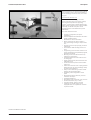
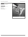
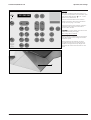
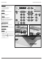
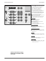


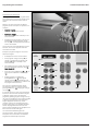
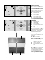


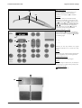
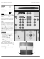
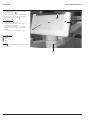
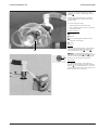


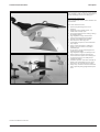
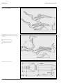
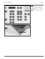
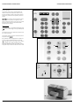
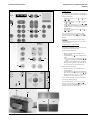

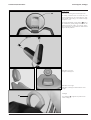


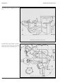

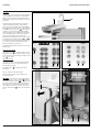

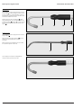
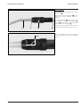
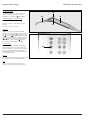
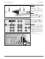
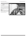
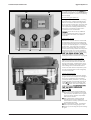
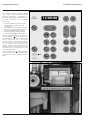

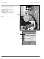


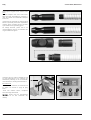

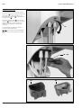
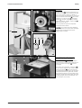


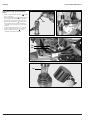
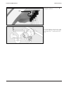
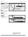
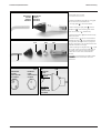


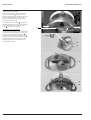
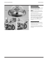

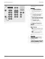

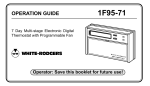

![PLAS A O ]-OR](http://vs1.manualzilla.com/store/data/005852706_1-5db0b7ed584537f0e62af161fb124638-150x150.png)