1
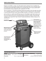
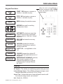
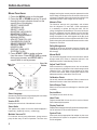
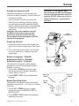
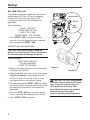
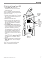
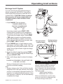
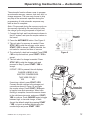
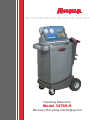
O
p
e
r
a
t
i
n
g
M
a
n
u
a
l
Operating Manual for
Model 34788-H
Recovery, Recycling, Recharging Unit
Model 34788-H
Recovery, Recycling, & Recharging Unit
SAFETY DEFINITIONS: Follow all WARNING, CAUTION, and NOTE messages in this manual. These messages are defined as
follows: WARNING means you may risk serious personal injury or death; CAUTION means you may risk personal injury, property
damage, or unit damage; and NOTEs and OPERATING TIPS provide clarity and helpful information. These safety messages cover
situations ROBINAIR is aware of. ROBINAIR cannot know, evaluate, and advise you as to all possible hazards. You must verify that
conditions and procedures do not jeopardize your personal safety.
DISCLAIMER: Information, illustrations, and specifications contained in this manual are based on the latest information available
at the time of publication. The right is reserved to make changes at any time without obligation to notify any person or organization
of such revisions or changes. Further, ROBINAIR shall not be liable for errors contained herein or for incidental or consequential
damages (including lost profits) in connection with the furnishing, performance, or use of this material. If necessary, obtain additional
health and safety information from the appropriate government agencies and the vehicle, refrigerant, and lubricant manufacturers.
WARNINGS
ALLOW ONLY QUALIFIED PERSONNEL TO OPERATE THE UNIT. Before operating the unit, read and follow
the instructions and warnings in this manual. The operator must be familiar with air conditioning and refrigeration
systems, refrigerants, and the dangers of pressurized components. If the operator cannot read this manual,
operating instructions and safety precautions must be read and discussed in the operator’s native language.
PRESSURIZED TANK CONTAINS LIQUID REFRIGERANT. Do not overfill the internal storage vessel, because
overfilling may cause explosion and personal injury or death. Do not recover refrigerants into nonrefillable
containers; use only federally authorized refillable containers (DOT spec. 4BW or 4BA).
HOSES MAY CONTAIN LIQUID REFRIGERANT UNDER PRESSURE. Contact with refrigerant may cause
personal injury. Wear protective equipment, including safety goggles. Disconnect hoses using extreme caution.
AVOID BREATHING A/C REFRIGERANT AND LUBRICANT VAPOR OR MIST. Exposure may irritate eyes,
nose, and throat. To remove refrigerant from the A/C system, use only equipment certified for the type of
refrigerant being removed.
DO NOT USE AN EXTENSION CORD. An extension cord may overheat and cause fire. If you must use an
extension cord, use the shortest possible cord with a minimum size of 14 AWG.
TO REDUCE THE RISK OF FIRE, do not use the unit in the vicinity of spilled or open containers of gasoline
or other flammable substances.
CAUTION—DO NOT PRESSURE TEST OR LEAK TEST EQUIPMENT AND / OR VEHICLE AIR CONDITIONING SYSTEMS WITH COMPRESSED AIR. Some mixtures of air and refrigerant have been shown to be
combustible at elevated pressures. These mixtures, if ignited, may cause injury or property damage.
TO PREVENT CROSS-CONTAMINATION, USE THIS UNIT WITH R-134A REFRIGERANT ONLY. The unit is
designed to recover, recycle, and recharge only R-134a refrigerant. Do not attempt to adapt the unit for another
refrigerant. Do not mix refrigerant types through a system or in the same container; mixing of refrigerants will
cause severe damage to the unit and the vehicle air conditioning system.
HIGH VOLTAGE ELECTRICITY INSIDE THE UNIT HAS A RISK OF ELECTRICAL SHOCK. Exposure may
cause personal injury. Disconnect the power before servicing the unit.
Additional health and safety information may be obtained
from the refrigerant and lubricant manufacturers.
OPERATING NOTE: At temperatures exceeding 120° F / 49° C, wait 10 minutes between recovery jobs.
Table of Contents
Introduction . . . . . . . . . . . . . . . . . . . . . . . . . . . . . . . . . . . . . . . . . . . . . . . . . . 2
Technical Specifications . . . . . . . . . . . . . . . . . . . . . . . . . . . . . . . . . . . . . . 2
Keypad Functions . . . . . . . . . . . . . . . . . . . . . . . . . . . . . . . . . . . . . . . . . . . 3
Glossary . . . . . . . . . . . . . . . . . . . . . . . . . . . . . . . . . . . . . . . . . . . . . . . . . . 3
Menu Functions . . . . . . . . . . . . . . . . . . . . . . . . . . . . . . . . . . . . . . . . . . . . 4
Setup . . . . . . . . . . . . . . . . . . . . . . . . . . . . . . . . . . . . . . . . . . . . . . . . . . . . . . 5
Unpack the Accessory Kit . . . . . . . . . . . . . . . . . . . . . . . . . . . . . . . . . . . . . 5
Power Up the Unit . . . . . . . . . . . . . . . . . . . . . . . . . . . . . . . . . . . . . . . . . . . 5
Select a Language . . . . . . . . . . . . . . . . . . . . . . . . . . . . . . . . . . . . . . . . . . 5
Select Operating Units . . . . . . . . . . . . . . . . . . . . . . . . . . . . . . . . . . . . . . . 5
Set Tank Fill Level . . . . . . . . . . . . . . . . . . . . . . . . . . . . . . . . . . . . . . . . . . . 6
Add Oil to the Vacuum Pump . . . . . . . . . . . . . . . . . . . . . . . . . . . . . . . . . . 6
Fill the Internal Storage Vessel . . . . . . . . . . . . . . . . . . . . . . . . . . . . . . . . . 7
Operating Instructions . . . . . . . . . . . . . . . . . . . . . . . . . . . . . . . . . . . . . . . . . 8
Recover Refrigerant from a Vehicle . . . . . . . . . . . . . . . . . . . . . . . . . . . . . 8
Evacuate the A/C System . . . . . . . . . . . . . . . . . . . . . . . . . . . . . . . . . . . . . 9
Replenish A/C System Oil . . . . . . . . . . . . . . . . . . . . . . . . . . . . . . . . . . . . 10
Recharge the A/C System . . . . . . . . . . . . . . . . . . . . . . . . . . . . . . . . . . . 11
Operating Instructions — Automatic . . . . . . . . . . . . . . . . . . . . . . . . . . . . 13
System Flush . . . . . . . . . . . . . . . . . . . . . . . . . . . . . . . . . . . . . . . . . . . . . . . 15
Maintenance . . . . . . . . . . . . . . . . . . . . . . . . . . . . . . . . . . . . . . . . . . . . . . . . 18
General . . . . . . . . . . . . . . . . . . . . . . . . . . . . . . . . . . . . . . . . . . . . . . . . . . 17
Electrical Protection . . . . . . . . . . . . . . . . . . . . . . . . . . . . . . . . . . . . . . . . 17
Manually Fill the Internal Storage Vessel (ISV) . . . . . . . . . . . . . . . . . . . 17
Tank Fill Hose Filter Service . . . . . . . . . . . . . . . . . . . . . . . . . . . . . . . . . . 18
Replace the Filter-Drier . . . . . . . . . . . . . . . . . . . . . . . . . . . . . . . . . . . . . . 19
Adjust Tank Fill Level . . . . . . . . . . . . . . . . . . . . . . . . . . . . . . . . . . . . . . . 20
Change Vacuum Pump Oil . . . . . . . . . . . . . . . . . . . . . . . . . . . . . . . . . . . 21
Scale Calibration Check . . . . . . . . . . . . . . . . . . . . . . . . . . . . . . . . . . . . . 22
Check for Leaks . . . . . . . . . . . . . . . . . . . . . . . . . . . . . . . . . . . . . . . . . . . 22
Replacement Parts . . . . . . . . . . . . . . . . . . . . . . . . . . . . . . . . . . . . . . . . . 23
Spanish Manual . . . . . . . . . . . . . . . . . . . . . . . . . . . . . . . . . . . . . . . . . . . . . 25
French Manual . . . . . . . . . . . . . . . . . . . . . . . . . . . . . . . . . . . . . . . . . . . . . . 49
Safety Precautions . . . . . . . . . . . . . . . . . . . . . . . . . . . . . Inside Front Cover
Warranty . . . . . . . . . . . . . . . . . . . . . . . . . . . . . . . . . . . . . Inside Back Cover
IMPORTANT: To comply with federal law governing A/C system service, you must complete and mail
the MVAC Certification Form included in the accessory kit. Technicians using this equipment must
be certified under EPA Section 609 (Environmental Protection Agency). For more information, read
the MACS information included in the accessory kit, or visit the MACS website at www.macsw.org.
To validate the warranty provided by Robinair, complete the warranty card included in the accessory
kit, and mail it within ten days from the purchase date of the unit.
560826 Rev. D, August 23, 2013
1
Introduction
Robinair No. 34788-H is used on R-134a vehicles and is designed to be compatible with
existing service equipment and standard service procedures. This unit is a UL-listed, singlepass system that meets SAE specifications for recycled refrigerant. Follow the SAE-J2211
recommended service procedure for the containment of R-134a.
The unit includes a 1.5 cfm (42 l/m) Robinair high vacuum pump for fast, thorough evacuation.
The compressor pulls the A/C system to 0 psig, then works in series with the vacuum pump
to achieve highly efficient recovery and immediate recharge. If the system is not opened for
service, there is no need to pull additional vacuum. If the system is opened for service, use
the unit’s vacuum cycle to remove air and moisture from the A/C system. (We recommend
a minimum 15-minute vacuum, or follow the vehicle manufacturer’s specs.) Note: R-134a
systems require special oils. Refer to the A/C system manufacturer’s service manual for oil
specifications.
Control Panel:
folds flat for storage.
Manifold Gauges:
connect to vehicle A/C
system; show system’s
low-side and high-side
pressure.
Flow Indicators: red
light indicates high-side
flow from vehicle A/C
system through unit;
blue light indicates lowside flow from vehicle
A/C system through unit.
Digital Display: visual
interface between
operator and machine.
Main Power Switch:
supplies electrical
power to unit.
Tool Storage Areas
(additional storage
on back side for
extra filter-driers and
oil bottles).
Technical Specifications
Voltage . . . . . . . . . . . . . . . . . . . . . . . 115V, 60 Hz
Pump Free-Air Displacement . . 1.5 cfm (42 l/m)
Operating Range . . . 50° to 120° F (11° to 49° C)
Dimensions . . . . . . . . . . . 49" H x 34" W x 23" D
. . . . . . . . . . . . (124.5 cm x 86.4 cm x 58.4 cm)
Filter-Drier . . . . . . . . . . . . 43 cu. in. spin-on type
2
Introduction
Keypad Functions
START
YES
START / YES begins or resumes a
function, or answers a query.
STOP
NO
STOP / NO terminates or pauses a
function, or answers a query.
When the unit is not performing a
function, pressing the UP or DOWN
arrow key adjusts contrast on the
digital display.
MENU displays the selection menu.
MENU
ARROWS are used for scrolling
through menu items.
AUTOMATIC activates a menu that
helps the user set up an automatic
recover / vacuum / leak test / charge
sequence.
AUTOMATIC
RECOVER
RECOVER activates the recovery
sequence.
VACUUM
VACUUM activates the vacuum
sequence, followed by an option to
activate a leak test.
INJECT OIL
INJECT OIL – not applicable to this
unit.
CHARGE
CHARGE charges the vehicle A/C
system with a programmed amount of
refrigerant.
REFRIGERANT
DATABASE
REFRIGERANT DATABASE (optional)
offers access to system oil and
refrigerant specifications by vehicle
model and year. Purchase Robinair
No. 34411.
Keypad
Glossary
A/C System : The vehicle air conditioning system being serviced.
Internal Storage Vessel : The refillable refrigerant storage vessel
designed specifically for this unit; 30 lb. (14 kg).
Source Tank : A disposable tank of new refrigerant used to refill
the internal storage vessel; not included.
Unit : Model No. 34788-H.
560826 Rev. D, August 23, 2013
3
Introduction
Menu Functions
1.Press the MENU button on the keypad.
2.Press the UP or DOWN arrow key to scroll
through the menu choices shown on the
second line of the display :
SELECT LANGUAGE
VERSION X.XX
SELECT UNITS
MAINTAIN VACUUM OIL
MAINTAIN FILTER
REFRIG MANAGEMENT
MANUAL REFILL
ADJUST TANK FILL LVL
CALIBRATION CHECK
SELECT BEEPER TONE
SERVICE MENU
HOSE FLUSH
DISPLAY TANK INFO
SYSTEM FLUSH
3.Press START / YES to make a choice
from the menu. Press STOP / NO to pause
during any process, and STOP / NO a
second time to exit a process.
Start / Yes
Button
Stop / No
Button
Arrow
Keys
displays how long the vacuum pump has operated since the
last oil change, and allows the user to reset the value once an
oil change is complete. Refer to the instructions outlined in the
Maintenance section under Change Vacuum Pump Oil.
Maintain Filter
The filter-drier removes acid, particulates, and moisture
from the refrigerant. To meet SAE J-2788 requirements,
it is mandatory to replace the filter-drier after 150 lbs.
(68 kg) of refrigerant has been filtered. This menu item shows
how much refrigerant has been filtered since the last filter
change, and allows the user to reset the value once a filter
change is complete. A code, which appears on the filter, must
be entered into the unit to ensure compliance with SAE J-2788.
Refer to instructions outlined in the Maintenance section under
Replace the Filter-Drier.
Refrig Management
Displays the amount of refrigerant recovered, charged, and
replenished (for the life of the unit), and filtered (since the last
filter change).
Manual Refill
Use to transfer refrigerant from the source tank to the internal
storage vessel (ISV). Refer to instructions outlined in the
Maintenance section under Manually Fill the ISV.
Adjust Tank Fill LVL
When connected to a refrigerant source, the unit maintains
a pre-set amount of refrigerant in the internal storage vessel
(default is 15 lbs.). This value may be adjusted up or down
to suit the user’s needs. Refer to instructions outlined in the
Maintenance section under Adjust Tank Fill Level.
Calibration Check
Use to verify internal scale calibration. Refer to instructions in
Maintenance section under Scale Calibration Check.
Select Beeper Tone
Menu
Button
Select Language
Operator may choose to have prompts displayed in one of three
languages: English, Spanish, or French.
Version X.XX
Displays the revision level of the software in the unit.
Select Units
The operator may choose to have test results displayed in
Imperial (lb.), Imperial (lb. and oz.), or Metric (kg).
Maintain Vacuum Oil
For maximum vacuum pump performance, change vacuum
pump oil after every 10 hours of operation. This menu item
4
Select one of two tones for an alert signal, or mute the signal
completely.
Service Menu
For Robinair service center use only.
Hose Flush
Flushes residual PAG oil from the unit for service of electric
POE oil-based hybrid systems.
Display Tank Info
Displays internal storage vessel (ISV) pressure and temperature.
Use to check the ISV for excessive pressure.
System Flush
When used with the appropriate flush adapter kit, this menu
item allows the A/C system or component to be flushed with
R-134a refrigerant.
Setup
Unpack the Accessory Kit
Unpack the accessory kit from the bag, and
remove the plastic packaging. The kit consists of
• A calibration weight.
• Vacuum pump oil, oil filler cap, and tube.
• Plastic pouch containing a warranty card (to
be completed and mailed), applicable MSDS
sheets, a service center listing, and an envelope
of Mobile Air Conditioning Society (MACS)
information.
Important: You must complete and mail
the MVAC Certification Form and your
technicians must be certified with the
Environmental Protection Agency (EPA)to
operate this equipment.
CAUTION: R-134a systems have
special fittings (per SAE specifications)
to avoid cross-contamination with R-12
systems. DO NOT adapt your unit for a
different refrigerant — system failure
will result.
Main
Power Switch
Power
Cord
Power Up the Unit
1.Unwind the power cord from the handle, and
plug it into a correct voltage outlet. See Figure
1.
2.Turn on the main power switch. The first time
the unit is powered up, it displays the initial
setup mode.
Select a Language – English
Seleccionar Idioma – Espanol
Selection Langue – Francais
The operator may choose to have prompts
displayed in one of three languages: English,
Spanish, or French.
1.Use the UP or DOWN arrow key to toggle
through the choices of English, Spanish, or
French. Refer to Figure 2.
2.Press START / YES to select the displayed
language.
Select Operating Units
The operator may choose to have test results
displayed in Imperial (lb., or lb. and oz.) or Metric
(kg) units.
1.Use the UP or DOWN arrow key to toggle
through the choices of IMPERIAL UNITS or
METRIC UNITS.
2.Press START / YES to select the displayed
operating unit choice.
560826 Rev. D, August 23, 2013
Figure 1
Start / Yes
Button
Stop / No
Button
Arrow
Keys
Figure 2
5
Setup
Set Tank Fill Level
The operator may either accept the unit’s pre-set
default weight of 15 lbs. (6.8 kg) of refrigerant
stored in the internal storage vessel (ISV),
or change the amount to accommodate the
application.
Vacuum Pump
Fill Port
Sight
Glass
The unit displays
LEVEL: 15.00 LBS.
ENTER TANK FILL LVL
LIMIT: 4 TO 17 LBS.
PRESS START / YES TO SAVE
1.Press START / YES to accept the default
amount, or use the keypad to enter a desired
amount and press START / YES.
Add Oil to the Vacuum Pump
CAUTION: The vacuum pump is shipped
without oil in the reservoir. Failure to add oil to
the vacuum pump will damage the pump.
Fill Port
The unit displays
ADD 5 OZ OF NEW OIL
TO VACUUM PUMP
START TO CONTINUE
1.Remove the brass plug from the vacuum pump
oil fill port. See Figure 3.
2.Attach the flexible tube/cap to the oil bottle; pour
only five (5) ounces of vacuum pump oil into
the fill port. Note: You will top off the oil in the
next step as the vacuum pump is running.
3.Press and release the START / YES key. While
the vacuum pump is running, slowly add oil until
the level rises to the center of the reservoir’s
sight glass.
4.Press the STOP / NO key to stop the vacuum
pump, and install the brass plug in the fill port.
5.Press START / YES to continue.
6
Figure 3
Sight Glass
CAUTION: The unit is programmed
to run the setup procedure as outlined
here. To prevent personal injury, do
NOT operate the unit at any other
time without the brass plug installed,
because the vacuum pump is
pressurized during normal operation.
Setup
Fill the Internal Storage Vessel (ISV)
1.Press START / YES, and the unit
automatically runs a 5-minute vacuum to
clear all internal air.
Note: The “burping” noise heard during this
process indicates air is being purged from the
system—this is normal.
Low- and
High-Side
Hoses
2.After the vacuum pump shuts off, connect
the fill hose to the liquid connector on a
full source tank.
3.Open the source tank valve.
Power
Cord
4.Install the source tank, and secure it to
the unit (using the tank strap) in such a
way that liquid refrigerant is supplied to
the connection.
Fill Hose
(connect to
liquid line)
5.Press START / YES to begin filling the
internal storage vessel. Add at least 8 lbs.
(3.6 kg) of refrigerant to ensure enough
refrigerant is available for charging.
Source
Tank
Strap
This process takes 15–20 minutes. The
unit stops when a sufficient amount of
refrigerant has been transferred to the
internal tank, or when the source tank is
empty.
Press STOP / NO to pause. Press STOP
/ NO again to exit, or START / YES to
resume.
Figure 4
Side View
6.When the fill process is complete, press
STOP / NO to exit. The unit is ready for
operation.
Note: There is no need to calibrate the
scale; it is calibrated at the factory.
560826 Rev. D, August 23, 2013
7
Operating Instructions
Recover Refrigerant from a Vehicle
1.Empty the oil drain bottle located on the righthand side of the unit, if necessary, or make note
of the current oil level. See Figure 5.
2.Connect the high- and low-side hoses to the
vehicle A/C system.
3.Open the coupler valves on the hoses.
4.Press the RECOVER button.
Note: The clicking noise heard during the recovery
process indicates the solenoid is opening and
closing — this is normal.
5.When the system has recovered to 0 psi, the
vacuum pump automatically starts and runs until
recovery is complete. The unit then goes into an
automatic oil drain—this may require up to 90
seconds to complete.
6.After the oil drain is complete, the display shows
Oil Drain
Bottle
Figure 5
RECOVER COMPLETE
RECOVERED XX.XX LBS. (X.XX KG)
CHECK OIL BOTTLE
Note: The displayed recovered weight can vary,
depending on ambient conditions, and should not
be used as an indicator of scale accuracy.
7.Check the oil drain bottle, and note the amount
of oil that was removed from the A/C system.
This is the amount of new oil that must be
charged into the A/C system after the service is
complete.
• Use only new oil to replace the oil removed
during the recycling process.
• Dispose of used oil according to local, state,
and federal regulations.
Recovery is complete. You are now ready to either
advance to the charge process, or to make repairs
to the A/C system followed by the evacuation
process.
8
Operating Tips
After the RECOVER function is selected :
• If system pressure is below 10 psi, the
display reads
LOW RECOVER PRESSURE
CHECK CONNECTIONS
until pressure increases, or the START /
YES button is pressed. Verify the high- and
low-side hoses are connected and coupler
valves are open. Press STOP / NO to exit.
• If 100 lbs. (45 kg) or more of refrigerant has
been recovered since the last filter-drier
change, the display reads
FILTER WEIGHT XXX LB (XX KG)
To meet SAE J-2788 requirements, it is
mandatory to replace the filter-drier after
150 lbs. (68 kg) of refrigerant has been
filtered. The unit gives a warning to replace
the filter when filter weight reaches 100 lbs.;
when filter weight reaches 150 lbs., the unit
locks out and ceases to operate. Refer
to instructions outlined in the Maintenance
section under Replace the Filter-Drier.
Operating Instructions
Evacuate the A/C System
1.Ensure service hoses are connected, and
coupler valves are OPEN.
2.Press VACUUM.
3.Press START / YES to accept the default
evacuation time of 10 minutes, or enter the
desired vacuum time using the number keys,
and press START / YES.
CAUTION: The unit pulls a vacuum on the
vehicle A/C system to remove air and boil off
moisture that may be present in the system.
Evacuate the system for at least 10 minutes,
or follow the A/C system manufacturer’s
specifications, to ensure adequate moisture
and contaminant removal.
4.The unit gives you the option of doing a leak
test after evacuation.
Press START / YES to perform the leak test.
Press STOP / NO to skip the leak test and begin
evacuation.
5.The unit starts the vacuum pump to evacuate
the A/C system and stops when the specified
amount of time has elapsed.
Press STOP / NO to pause the process. Press
START / YES to resume, or STOP / NO again
to exit.
You are now ready to replenish the A/C system
with new oil, if necessary, or to recharge the
system with refrigerant.
Operating Tips
• If the vacuum pump has run for 10 or
more hours without an oil change, the
unit displays
VACUUM OIL TIME XX:XX
CHANGE OIL NOW?
Refer to instructions outlined in the
Maintenance section under Change
Vacuum Pump Oil.
• Before the unit begins evacuating the A/C
system, it checks for any pressure in the
system that might damage the vacuum
pump. If pressure is detected, the unit
displays
PRESSURE EXISTS
PRESS ANY KEY TO EXIT
Press any key to exit, and recover
refrigerant before proceeding.
• If a leak test was selected at the end of
vacuum, and a leak is detected, the unit
displays
LEAK TEST FAILED
PRESS ANY KEY TO EXIT
Press any key to exit the evacuation,
perform needed repairs, and repeat the
evacuation.
• To ensure an accurate leak test, it is
imperative that a thorough recovery and
evacuation of the system be performed.
During the recovery process, cold spots
can develop in the automotive system.
Pockets of refrigerant in desiccant and
in system oil will continue to vaporize as
the A/C system temperature equalizes
toward ambient. As this occurs, A/C
system pressure will increase, which may
be interpreted by the unit as a leak.
This will vary somewhat with ambient
temperature conditions.
560826 Rev. D, August 23, 2013
9
Operating Instructions
Replenish A/C System Oil
Oil may be replenished after the charge cycle by
using an oil inject tool. Use separate oil inject tools
for PAG and POE systems to prevent oil crosscontamination.
CAUTION : To prevent damage to equipment,
•Use only NEW oil to replace the oil removed
during the recycling process.
•Charge only the amount of oil that was
removed from the A/C system during the
recovery process. If no oil was removed from
the A/C system during recovery, DO NOT
charge any oil into the A/C system.
Empty the oil drain bottle before recovering an A/C
system to prevent an inaccurate oil charge.
1.Refer to the vehicle service manual to
determine the correct oil for the A/C system
being serviced.
2.Check the oil drain bottle to determine the
amount of oil that was removed. See Figure 6.
3.Follow instructions included with your oil inject
tool.
10
Oil Drain Bottle
Figure 6
Operating Instructions
Recharge the A/C System
If you are servicing a hybrid vehicle having an
electric compressor with POE oil, first perform
a brief hose flush procedure to clear the unit of
residual PAG oil. CAUTION: Failure to perform
this procedure will cause contamination of
the hybrid system as well as failure of the
compressor.
1.Press CHARGE. The unit displays
Storage Port
Connections
CHARGE HYBRID W/ AN
ELECTRIC COMPRESSOR
THAT USES POE OIL?
YES NO
If servicing a hybrid, press START / YES.
Connect service couplers to the storage port
connections at the rear of the unit (see Figure
7), and open the coupler valves. Press START
/ YES again to begin a hose flush procedure.
When hose flushing is complete, connect the
service hoses to the vehicle service ports, and
press START / YES to continue.
Figure 7
Blue light indicates
Low-Side Charge
Red light indicates
High-Side Charge
2.Press CHARGE again to toggle between a highside charge, a low-side charge, or both. Note: The
blue light on the control panel indicates a low-side
charge; the red light indicates a high-side charge.
See Figure 8.
3.Accept the default weight by pressing START /
YES, or type in a weight using the number keys,
and press START / YES.
4.After a valid charge weight is entered, the display
reads
CHARGE IN PROGRESS / DO NOT DISTURB
X.XX LBS. (X.XX KG)
Moving or bumping the unit at this point may
result in an incorrect reading.
Note:
• During a charge cycle, if the unit fails to transfer
refrigerant due to low tank pressure, the charge
process is automatically interrupted and the unit
operates in a mode to build tank pressure. Once
tank pressure is sufficient, the unit automatically
completes the charge.
560826 Rev. D, August 23, 2013
Figure 8
Operating Tips
After selecting the CHARGE function and
entering a desired weight, if the weight
entered will leave less than 2 lbs. (.91
kg) of refrigerant in the internal tank after
charge, the charge function will not start.
The display reads
INSUFFICIENT REFRIG.
PRESS ANY KEY TO EXIT
Refer to the Maintenance section of this
manual for instructions to Manually Refill
the Internal Storage Vessel (ISV).
11
Operating Instructions
Recharge the A/C System contd.
• When the charge cycle gets close to the weight
entered in Step 3, the unit slows down. It will
charge, settle, charge again, settle, etc., with
the blue/red lights illuminating accordingly.
5.When the charge is complete, the display reads
CHARGED XX.XX LBS
DISCONNECT HS HOSE
DISCONNECT LS HOSE
START TO CONTINUE
Remove the service hoses from the vehicle A/C
system.
IMPORTANT: If the low-side or high-side
coupler valves are left open, the system will
pull the refrigerant back out of the vehicle.
6. Press START / YES to begin clearing the
hoses.
CLEARING HOSES
PLEASE WAIT
When the hoses are cleared, the display reads
CHARGE COMPLETE
CHARGED XX.XX LBS
ANY KEY EXITS
The A/C system is now ready for use.
12
Operating Instructions – Automatic
The automatic function allows a user to program
an automatic recovery, vacuum, leak test, and / or
charge sequence. The user may choose to skip
any step in the automatic operation during the
programming. A total automatic sequence may
take an hour to complete.
Note: Oil recovered during the recovery cycle can
be manually injected by the user before or after
the charge cycle using a separate oil inject tool.
1.Connect the high- and low-side service hoses to
the A/C system, and open the coupler valves on
the hoses.
Automatic
Function
2.Press the AUTOMATIC button. See Figure 9.
3.The unit asks if a recovery is needed. Press
STOP / NO to skip the recovery cycle; press
START / YES to accept. If NO is selected, the
unit asks for vacuum and time of vacuum.
4.The unit asks if a leak test is needed. Press STOP
/ NO to skip the leak test; press START / YES to
accept.
Figure 9
5.The unit asks if a charge is needed. Press
STOP / NO to skip the charge cycle and
proceed to Step 6; press START / YES to
accept.
If START / YES is pressed, the unit displays
CHARGE HYBRID W/ AN
ELECTRIC COMPRESSOR
THAT USES POE OIL?
YES NO
If servicing a hybrid, press START / YES.
Connect service couplers to the storage port
connections shown in Figure 10, and open
the coupler valves. Press START / YES again
to begin a hose flush procedure. When hose
flushing is complete, connect the service hoses
to the vehicle service ports, and press START /
YES to continue. Press CHARGE again to toggle
between high- or low-side charge, or both.
Accept the default weight by pressing START
/ YES, or type in a desired weight using the
number keys and press START / YES.
560826 Rev. D, August 23, 2013
Storage Port
Connections
Figure 10
13
Operating Instructions – Automatic
6.The display shows an overview of all the tests
that were selected. Press START / YES to
begin the automatic sequence.
7.When the sequence is complete, the display
shows the amount of refrigerant that was
recovered and charged.
8.Close the high- and low-side coupler valves,
and remove the service hoses from the A/C
system. Press START / YES to clear hoses.
Operating Tips
• If the weight entered is more than the
refrigerant available in the internal tank, the
charge function will not start. The display
reads
INSUFFICIENT REFRIG.
PRESS ANY KEY TO EXIT
Refer to the Maintenance section of this manual
for instructions to Manually Fill the ISV.
• If problems are encountered during the
automatic sequence, the unit will “beep” three
times and the control panel readout will pinpoint
the problem encountered. The sequence
remains paused until the user enters a decision
regarding how to proceed.
• Before the unit begins evacuating the A/C
system during the automatic sequence, it
checks for any pressure in the system that
may damage the vacuum pump. If pressure is
detected, the unit displays
PRESSURE EXISTS
PRESS ANY KEY TO EXIT
Press any key to exit the automatic
sequence.
• If a leak test was programmed, and a leak is
detected, the unit displays
LEAK TEST FAILED
PRESS STOP TO EXIT
PRESS START TO CONTINUE
Press STOP to exit the automatic sequence
and perform needed repairs. Press START to
continue the automatic sequence despite the
failed leak test.
• To ensure an accurate leak test, it is
imperative that a thorough recovery and
evacuation of the system is performed.
During the recovery process, cold spots can
develop in the automotive system. Pockets
of refrigerant in desiccant and in system oil
will continue to vaporize as the A/C system
temperature equalizes toward ambient. As
this occurs, A/C system pressure increases,
which may be interpreted by the unit as a
leak. This varies somewhat with ambient
temperature conditions.
14
System Flush
System Flushing Process
This unit provides a method of removing oil by forcing liquid refrigerant through an A/C
system, or components of an A/C system. A special flushing adapter, which is available as an
accessory, accesses the A/C system at the compressor block. After flushing, the refrigerant is
recovered by the unit and filtered by the recycling circuit, returning it to SAE purity levels.
A/C systems vary and may require the adapting and flushing of individual components. The
following procedure works with an orifice tube system. Refer to any service bulletins as needed
during this procedure.
Notes:
• The unit must have at least 10 lbs. of refrigerant available in the ISV (as indicated on the
display) for charging.
• If the flush process is interrupted by an accidental power-down or other fault, use the
Recover mode to remove the refrigerant from the vehicle.
Setup
1.Verify the oil drain bottle on the side of the unit
is empty. See Figure 11. Recover refrigerant as
outlined in this manual under Recover Refrigerant
from a Vehicle.
2.Close service coupler valves and disconnect hoses
from vehicle access ports.
3.Close the valve on the external source tank.
Note: During this procedure, up to 12 lbs. of
refrigerant is charged into the vehicle A/C system.
If the flushing cycle is stopped before it is complete
and the external source valve is open, the unit
automatically adds refrigerant to the ISV. There
will be no room to recover the refrigerant used for
flushing.
4.Remove the A/C system orifice tube, and reconnect
the fittings to create a bypass.
Oil Drain
Bottle
Figure 11
5.Disconnect the compressor block at the rear of the
compressor.
6.Attach the compressor block adapter (from the
flushing kit) to the system side of the compressor
block.
7.Configure the block connectors to provide forwardor back-flushing of the refrigerant, which flows from
the unit through the red high-side connection hose.
Open the red service coupler.
8.Connect the filter housing to the desired return side
of the adapter block and to the blue low-side hose.
Open the blue service coupler.
560826 Rev. D, August 23, 2013
15
System Flush
9.Verify that a flushing filter is correctly installed
in the flushing filter housing. Open the isolation
valve on the hose.
Operating Instructions
1.Press the MENU button on the keypad.
2.Press the UP or DOWN arrow key to scroll
through the menu choices until SYSTEM
FLUSH is displayed. Press START / YES.
3.Press START / YES to accept the default flush
time of 10 minutes, or enter the desired flush
time using the number keys. Press START /
YES.
4.The unit automatically runs the vacuum pump
for five minutes to remove air from the A/C
system.
5.The unit flushes the system for the designated
length of time, and then enters a recovery
mode. Note: If the external flushing filter gets
plugged, the unit displays
WARNING: Do NOT disconnect
service couplers during the flushing
process. Refrigerant would spray
out of the fittings, and exposure may
cause personal injury.
FLUSH FILTER BLOCKED
RETRY?
Press START / YES to retry. Press STOP /
NO to end the flush process and recover the
refrigerant. With the refrigerant recovered, the
filter can be serviced and the process repeated.
The message repeats until the filter is replaced.
6.Oil that has been collected drains into the
graduated oil drain bottle. Remove the bottle
and measure the oil.
Dispose of oil according to the laws in your
jurisdiction. It is the responsibility of the user to
determine if a material is a hazardous waste at
the time of disposal.
7.When the unit displays FLUSHING
COMPLETE, close service couplers, remove
hoses, and reassemble the vehicle’s A/C
system to its original state.
8.Open the valve on the source tank.
9.Evacuate and recharge the vehicle according to
the instructions in this manual.
16
CAUTION: To prevent vehicle damage,
use a separate oil inject tool to replace
the system oil. Flushing removes
all oil from the system except what
remains in the compressor.
Maintenance
General Maintenance
1.On a regular basis, wipe off the unit using a
clean cloth to remove grease and dirt.
2.Periodically check internal components for
leaks; over time, fittings can loosen as the unit
is moved. Open the door panel, and trace lines
using a leak detector. Check connections on
the back of the unit. Tighten any loose fittings or
connections you may find.
Circuit
Electrical Protection
Breaker
The unit is equipped with a 15 amp circuit breaker
on the back panel. See Figure 12. If the breaker
trips, its button will pop out. A tripped circuit
breaker will cause the unit to lose all power.
Press the circuit breaker button to reset.
Manually Fill the
Internal Storage Vessel (ISV)
Figure 12
Back View
This menu item is used to transfer refrigerant from
a source tank to the internal storage vessel.
Note: If a refrigerant source tank remains
connected to the unit during normal operation, the
correct amount of refrigerant will be automatically
maintained in the ISV. The ISV may be manually
refilled, if necessary.
Low- and
High-Side
Hoses
1.Press Menu, and use arrow keys to select
MANUAL REFILL. Press START / YES. The
unit displays
Power
Cord
CONNECT SOURCE TANK
START TO BEGIN
Fill Hose
Source
Tank
Strap
2.Connect the fill hose to a full source tank, and
open the source tank valve.
3.Install the source tank, and secure it to the unit
with the source tank strap in such a way that
liquid refrigerant is supplied to the connection.
4.Press START / YES to begin. The display
shows
TANK FILL IN PROGRESS
TRANSFER XX LBS
5.The unit automatically stops when the preset
tank fill level is reached, or press STOP / NO to
exit.
560826 Rev. D, August 23, 2013
Figure 13
Side View
17
Maintenance
Tank Fill Hose Filter Service
The black tank fill hose at the rear of the machine
contains a filter that can be cleaned when it
appears that refrigerant flow is restricted.
When the machine senses low flow, it may display
the following message:
• SOURCE TANK EMPTY, but yet you know the
source tank contains refrigerant, connections
are secure, and the source tank valve is open.
The cause may be that the tank fill hose filter is
plugged.
Cleaning the Tank Fill Hose Filter
1. First ensure that pressure does not exist in the
line. Disconnect the external source tank,
and perform a manual tank fill to capture any
refrigerant in the line.
2. Slowly and carefully disconnect the tank fill
hose from the adapter. There may still be a
little pressure in the line.
3. Disassemble the tank fill hose at the filter
housing as shown in Figure 14.
4. Remove and clean the filter.
5. After the filter has been installed back into the
filter housing, torque the housing assembly to
8.5 N•m (6 ft. lbs.).
18
Disassemble the
Filter Housing
Figure 14
Maintenance
Replace the Filter-Drier
The filter-drier is designed to trap acid and
particulates, and to remove water from refrigerant.
To meet the SAE J-2788 mandate for adequate
moisture and contaminant removal, the filterdrier must be replaced after 150 lbs. (68 kg) of
refrigerant has been filtered.
Therefore, you no longer have a choice—the
filter-drier must be replaced. The unit gives a
warning when 100 lbs. of the filter capacity has
been used; the unit locks down when the 150
lb. filter capacity has been reached and will no
longer function. For this reason, always have a
spare Robinair No. 34724 filter-drier on hand.
Check Remaining Filter Capacity
1.Press MENU.
2.Use the arrow keys to scroll through the menu
to MAINTAIN FILTER, and press START / YES.
The unit displays
XXX LBS FILTERED
RECOVER LOCKOUT IN XXX LBS
REPLACE FILTER NOW?
PRESS STOP TO EXIT
3.Press STOP / NO to exit.
Change the Filter
1.Press MENU.
2.Use the arrow keys to scroll through the menu
to MAINTAIN FILTER, and press START / YES.
The unit displays
XXX LBS FILTERED
RECOVER LOCKOUT IN XXX LBS
REPLACE FILTER NOW?
PRESS STOP TO EXIT
3.Press START / YES to proceed.
4.If there is pressure in the filter, the unit begins
a clearing process. When complete, the display
reads ENTER 10 DIGIT SERIAL NUMBER.
Use the keypad to enter the serial number
that appears on the new filter-drier, and press
START / YES.
Note: If the display shows SERIAL NUMBER
ERROR, the serial number is invalid or the filterdrier has already been used in this unit.
560826 Rev. D, August 23, 2013
IMPORTANT: Use only authentic Robinair
No. 34724 filter-driers in this machine. All
performance tests and claims are based
on using this specific filter-drier.
And only the Robinair No. 34724 filterdrier includes the code necessary to
make the unit operable again.
Operating Tips
Enter the Serial No. for a New Filter-Drier
The numerical keys on the keypad include
an alphabet that is used to enter the serial
number code for the new filter-drier. The
procedure is similar to text messaging. For
example,
To enter an “A”:
Press the 2 key once
to see the “2” on the
digital display; press
the 2 key again to
display the “A”.
To enter a “C”:
Press the 2 key once
to see the “2” on the
digital display; press
the 2 key three more
times to see the “C”
on the display.
After the appropriate letter is shown on the
display, pause for a moment until the cursor
moves to the next position.
19
Maintenance
Replace the Filter-Drier contd.
5.The display reads PLEASE REPLACE FILTER.
Open the rear door of the unit and unscrew the
old filter. See Figure 15.
6.Look at the new filter—verify both o-rings are
lubricated and correctly located in the grooves.
See Figure 16. Thread the new filter into place.
Press START / YES.
FilterDrier
7.Close the door. Press STOP / NO to exit. The
filter-drier replacement is now complete.
Rear View
(without shroud)
Figure 15
Adjust Tank Fill Level
When connected to a refrigerant source, the unit
maintains a default value of 15 lbs. of refrigerant
in the internal storage vessel. This value may be
adjusted up or down to suit the application.
1.Press MENU.
2.Use the arrow keys to scroll through the menu
to ADJUST TANK FILL LVL, and press START /
YES. The unit displays
LEVEL: 15.00 LBS.
ENTER TANK FILL LVL
LIMIT: 4 TO 17 LBS.
PRESS START / YES TO SAVE
3.Use the keypad to enter a value between 4 lbs.
and 17 lbs., and press START / YES.
20
O-rings
Figure 16
Maintenance
Change Vacuum Pump Oil
Oil Fill Port
For maximum vacuum pump performance, change
the vacuum pump oil after every 10 hours of
operation. (The unit will display a prompt after 10
hours of operation.)
1.Press MENU. Use the arrow keys to select
MAINTAIN VACUUM OIL, and press START /
YES. The display shows how long the vacuum
pump has operated since the last oil change:
PUMP OIL TIME X:XX
TIME REMAINING X:XX
CHANGE OIL?
2.Press START / YES. The display shows
VACUUM OIL CHANGE TIME 2:00, and counts
down to zero. Allow the vacuum pump to run
until it automatically stops. The display then
shows DRAIN OLD OIL AND ADD 5 OZ NEW
OIL.
3.Refer to Figure 17, and remove the brass plug
from the vacuum pump’s oil fill port. (The pump
drains faster when vented.)
4.Remove the oil drain fitting cap, and drain the oil
into a suitable container for disposal. Replace
the cap.
5.Attach the flexible tube and cap to the oil bottle;
pour five (5) ounces of vacuum pump oil into the
fill port.
Oil Drain Fitting
Sight Glass
Figure 17
Review the laws in your jurisdiction
to determine the correct disposal
procedure for pump oil. It is the
responsibility of the user to determine
if a material is a hazardous waste at
the time of disposal. Ensure you are
in compliance with all applicable laws
and regulations.
6.Press START / YES. The display shows FILL
PUMP TO CENTER OF SIGHT GLASS, and the
vacuum pump starts. While the vacuum pump is
running, slowly add oil until the level rises to the
center of the reservoir’s sight glass.
7.Press STOP / NO. The counter resets to zero
after a vacuum pump oil change has been
completed.
8.Replace the brass plug on the fill port. Press
STOP / NO to exit to the Main Menu.
CAUTION: To prevent personal injury, do
NOT operate the unit at any time without the
brass plug installed, because the vacuum
pump is pressurized during normal operation.
560826 Rev. D, August 23, 2013
21
Maintenance
Scale Calibration Check
The calibration check is used to ensure that the
unit’s internal scale is always calibrated. During this
test, use only the calibration weight that is provided
with the unit.
1.Press Menu.
2.Use the arrow keys to scroll to CALIBRATION
CHECK.
3.Refer to Figure 18, and verify the magnet on the
bottom of the unit is clean. Press START / YES.
4.The display reads
ATTACH THE WEIGHT TO THE BOTTOM OF
THE MACHINE
PRESS START TO CONTINUE
5.Attach the weight provided to the magnet on the
bottom of the unit. Press START / YES.
• If the display shows CALIBRATION
APPROVED, the scale is in calibration. Press
any key to exit.
• If the display shows CALIBRATION REJECT,
the scale is out of calibration. Call your local
service center for assistance.
Magnet
Figure 18
• If the display shows CALIBRATION ERROR
1, verify the calibration weight is correctly
attached to the magnet, and verify the magnet
is clean with nothing attached to it. If that does
not correct the problem, call your local service
center for assistance.
Check for Leaks
Check the unit for leaks every three months, or as
specified by law in your jurisdiction.
1.Turn off MAIN POWER, and disconnect the
power cord from the outlet.
2.Open the rear door; remove top cover and front
panel.
3.Use a leak detector to probe all connections
for refrigerant leaks. Tighten fittings if a leak is
indicated.
4.Reassemble the body panels, and close the
rear door.
22
Inspect the unit periodically for leaks.
The manufacturer does not reimburse
for lost refrigerant.
Maintenance
Replacement Parts
Component
Replacement
Part No.
Filter-Drier
34724
Calibration Weight
540066
Service Coupler Set
(high- and low-side couplers)18192
Service Hose Set
(high- and low-side hoses) 34722
Vacuum Pump Oil
(case of 12 quarts)13203
Vacuum Pump Oil
(case of 4 gallons)13204
Maintenance Kit
13172
Low-side Hose Flush Storage Port 546883
High-side Hose Flush Storage Port546882
Vinyl Dust Cover (optional)17492
Taehicle Database
34411
Tank Fill Hose Filter
10233
560826 Rev. D, August 23, 2013
23
Notes
24
Robinair
Limited Warranty Statement
Declaración de garantía
limitada Robinair
Énoncé de la garantie limitée
de Robinair
Rev. November 1, 2005
This product is warranted to be free from
defects in workmanship, materials, and
components for a period of one year
from date of purchase. All parts and labor
required to repair defective products
covered under the warranty will be at no
charge. The following restrictions apply:
1. The limited warranty applies to the
original purchaser only.
2. The warranty applies to the product
in normal usage situations only, as
described in the Operating Manual.
The product must be serviced and
maintained as specified.
3. If the product fails, it will be repaired
or replaced at the option of the
manufacturer.
4. Transportation charges for warranty
service will be reimbursed by the factory
upon verification of the warranty claim
and submission of a freight bill for
normal ground service. Approval from
the manufacturer must be obtained prior
to shipping to an authorized service
center.
5. Warranty service claims are subject
to authorized inspection for product
defect(s).
6. The manufacturer shall not be
responsible for any additional costs
associated with a product failure
including, but not limited to, loss of
work time, loss of refrigerant, crosscontamination of refrigerant, and
unauthorized shipping and/or labor
charges.
7. All warranty service claims must be
made within the specified warranty
period. Proof-of-purchase date must be
supplied to the manufacturer.
8. Use of recovery/recycling equipment
with unauthorized refrigerants or
sealants will void warranty.
• Authorized refrigerants are listed on
the equipment or are available through
the Technical Service Department.
• The manufacturer prohibits the use
of the recovery/recycling equipment
on air conditioning (A/C) systems
containing leak sealants, either of a
seal-swelling or aerobic nature.
Revisión del 1 de noviembre de 2005
Se garantiza que este producto no posee
defectos de mano de obra, materiales y
componentes por el período de un año a
partir de la fecha de compra. Todas las
partes y mano de obra requerida para
reparar los productos con defecto cubiertos
bajo la garantía no tendrán costo. Aplican
las siguientes restricciones:
1. La garantía limitada aplica al comprador
original únicamente.
2. La garantía aplica al producto en
situaciones de uso normal únicamente,
como lo indica el Manual de
funcionamiento. Al producto se le debe
dar servicio y mantenimiento como se
especifica.
3. Si falla el producto, se debe reparar o
reemplazar a discreción del fabricante.
4. Los cargos de transporte de servicio
de garantía serán reembolsados por
la fábrica al verificar el reclamo de
garantía y presentar una boleta de flete
por servicio terrestre regular. Se debe
obtener la aprobación del fabricante
antes de hacer el envío a un centro de
servicio autorizado.
5. Los reclamos de servicio de garantía
están sujetos a inspección de defectos
del producto.
6. El fabricante no será responsable de
los costos adicionales relacionados con
fallas en el producto, que incluyen pero
no se limitan a, tiempo improductivo,
pérdida de refrigerante, contaminación
de refrigerante y envío no autorizado o
cargos por mano de obra.
7. Todo reclamo de servicio de garantía
se debe hacer dentro del período
de garantía establecido. Se debe
proporcionar la fecha de la prueba de
compra al fabricante.
8. El uso de equipo de recuperación/
reciclaje con refrigerantes o selladores
no autorizados anula la garantía.
• Los refrigerantes autorizados
se indican en el equipo o
están disponibles a través del
Departamento de servicio técnico.
• El fabricante prohíbe el uso de
equipo de recuperación/reciclaje
en sistemas de aire acondicionado
(A/C) con fugas de sellador, ya sea
porque un sello se infla o es de
naturaleza aeróbica.
This Limited Warranty
does NOT apply if:
Esta garantía limitada NO aplica
si:
Révisée le 1er novembre 2005
Ce produit est couvert contre les
défauts de matériau, de fabrication et de
composant pendant un an à compter de
la date d’achat. Toutes les pièces et la
main-d’œuvre nécessaires aux réparations
sous garantie sont sans frais. Toutefois, les
restrictions suivantes s’appliquent :
1. La garantie limitée s’applique
uniquement à l’acheteur initial.
2. La garantie s’applique uniquement au
produit utilisé dans des conditions de
fonctionnement normales conformément
au manuel d’utilisation. Il doit être
réparé et entretenu conformément aux
spécifications.
3. Si le produit subit une défaillance, il sera
réparé ou remplacé à la discrétion du
fabricant.
4. Les frais de transport pour les
réparations sous garantie sont
remboursés par l’usine après
l’évaluation de la réclamation au titre de
la garantie et après la soumission d’une
facture de transport terrestre standard.
L’approbation du fabricant est requise
avant l’expédition du produit à un atelier
de réparation autorisé.
5. Les réclamations au titre de la garantie
sont sujettes à l’inspection du produit
défectueux par un personnel autorisé.
6. Le fabricant ne peut être tenu responsable
pour tout coût supplémentaire lié à la
défaillance du produit incluant, sans
toutefois s’y limiter, les interruptions
de fonctionnement, la perte de liquide
frigorigène, la contamination des liquides
frigorigènes et l’expédition et/ou les frais
de main-d’œuvre soumis par des ateliers
non autorisés.
7. Toute réclamation pour des réparations
au titre de la garantie doit être soumise
durant la période de garantie. Une
preuve d’achat doit être fournie au
fabricant.
8. L’utilisation d’un appareil de récupération
et de recyclage avec du liquide
frigorigène ou des scellants non spécifiés
annule la garantie.
• Les liquides frigorigènes autorisés
sont indiqués sur l’appareil, ou ils
peuvent être obtenus auprès du
Service technique.
• Le fabricant interdit l’utilisation d’un
appareil de récupération et de recyclage
dans les systèmes de climatisation
contenant des colmatants pour fuites,
que ce soient des scellants à dilatation
ou aérobiques.
• The product, or product part, is broken
by accident.
• The product is misused, tampered with,
or modified.
• The product is used for recovering or
recycling any substance other than the
specified refrigerant type. This includes,
but is not limited to, materials and
chemicals used to seal leaks in A/C
systems.
• El producto, o parte de éste, se rompe
accidentalmente.
• El producto se usa incorrectamente, se
adultera o modifica.
• El producto se usa para recuperar
o reciclar cualquier sustancia que
sea diferente al tipo de refrigerante
establecido. Esto incluye, pero no se
limita a materiales y productos químicos
utilizados para sellar fugas en sistemas
de A/C.
Cette garantie limitée NE
s’applique PAS si le produit :
• ou une partie du produit a été
endommagé par un accident.
• a été utilisé de façon inadéquate, ou
qu’il a été altéré ou modifié.
• est utilisé pour la récupération et le
recyclage de substances autres que le
type de liquide frigorigène spécifié. Ces
substances comprennent, sans toutefois
s’y limiter, les matériaux et les produits
chimiques utilisés pour colmater les
fuites des systèmes de climatisation.
Visit our web site at www.robinair.com or call our toll-free
Technical Support Line at 800-822-5561
in the continental U.S. or Canada.
In all other locations, contact your local distributor. To help us serve you better, please be prepared to provide
the model number, serial number, and date of purchase of your unit.To validate your warranty, complete the
warranty card attached to the unit, and return it within ten days from date of purchase.
NATIONWIDE NETWORK OF AUTHORIZED SERVICE CENTERS
If your unit needs repair or replacement parts, contact the service center in your area. For help in locating a
service center, call the toll-free technical support line or visit www.robinair.com.
Visite nuestro sitio web en www.robinair.com o llame sin costo a
la línea de Asistencia técnica al 800-822-5561
en EE.UU. continental o Canadá.
En todas las demás ubicaciones, comuníquese con su distribuidor local. Para ayudarnos a servirle mejor, tenga a mano el número de
modelo, número de serie y fecha de compra de su unidad. Para validar la garantía, complete la tarjeta de garantía anexa a su unidad y
devuélvala dentro de los diez días siguientes a la fecha de compra.
RED NACIONAL DE CENTROS DE SERVICIO AUTORIZADOS
Si su unidad necesita reparaciones o partes de reemplazo, comuníquese con el centro de servicio de su área. Para obtener ayuda para
ubicar un centro de servicio, llame sin costo a la línea de asistencia técnica o visite www.robinair.com.
Visitez notre site Web à www.robinair.com ou appelez sans frais
le soutien technique au 800-822-5561
sur le territoire continental des États-Unis ou au Canada.
Pour tout autre endroit, communiquez avec votre distributeur local. Afin de nous aider à mieux vous servir, soyez prêt à nous donner le
numéro de modèle, le numéro de série et la date de l’achat de votre unité. Afin de valider votre garantie, remplissez la carte de garantie
jointe à votre système et retournez-la dans les dix jours de la date d’achat.
RÉSEAU NATIONAL DES CENTRES DE SERVICE AUTORISÉS
Si votre unité a besoin d’être réparée ou à besoin de pièces de remplacement, communiquez avec le centre de service de votre région.
Pour vous aider à localiser un centre de service, appelez sans frais la ligne de soutien technique ou visitez le www.robinair.com.
The Robinair 34788-H unit is designed to meet all applicable agency certifications, including Underwriter's Laboratories, Inc., SAE
Standards, and CUL. Certain state and local jurisdictions dictate that using this equipment to sell refrigerant by weight may not be
permitted. We recommend charging for any A/C service by the job performed. This weight scale provides a means of metering the
amount of refrigerant needed for optimum A/C system performance as recommended by OEM manufacturers
La unidad Robinair 34788-H está diseñada para cumplir con todas las certificaciones de agencia aplicables, incluyendo Underwriter’s Laboratories, Inc., Estándares SAE y CUL. Ciertas jurisdicciones estatales y locales prescriben que el uso de este equipo
para vender refrigerante por peso es posible que no sea permitido. Recomendamos que se cobre el trabajo realizado por dar
servicio al aire acondicionado. Esta escala de peso proporciona un medio para medir la cantidad de refrigerante que se necesita
para el rendimiento óptimo del sistema de aire acondicionado, tal como lo recomiendan los fabricantes OEM.
Le modèle 34788-H a été conçu pour répondre aux certifications applicables de la Underwriter’s Laboratories, Inc., aux normes
SAE et CUL. Certains endroits dictent l’utilisation de cet équipement et il peut arriver que la vente de fluide frigorigène en fonction
du poids puisse être interdite. Nous vous recommandons de facturer les services de climatisation en fonction du travail effectué.
Ce poids de tarification permet de calculer la quantité de fluide frigorigène nécessaire pour un rendement optimum de la climatisation, tel qu’il est recommandé par les fabricants de l’équipement d’origine.
Due to ongoing product improvements, we reserve the right to change design, specifications, and materials without notice.
Debido a las constantes mejoras del producto, nos reservamos el derecho de cambiar diseño, especificaciones y materiales sin aviso.
En raison des améliorations constantes apportées à nos produits, nous nous réservons le droit de changer de concept, de spécifications et de matériaux sans préavis.
655 EISENHOWER DRIVE
OWATONNA, MN 55060 USA
TECH SERVICES 800 822 5561
FAX 866 259 1241
CUSTOMER SERVICE 800 533 6127
FAX 800 322 2890
www.robinair.com
560826 (Rev. D, August 23, 2013)
© Bosch Automotive Service Solutions LLC