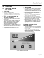
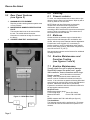
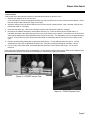
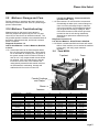
1
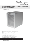
Plexus P2500
Aire Select System
Service Manual
PN 11615-000
Plexus Aire Select
Table of Contents
Section
Important
Description
Page
Before using the Plexus C/2500 please read and
understand the Plexus 2500 Manual and the SAFETY
PRECAUTIONS in section 1.0 (page 2) prior to each
application.
1.0
Contraindications/Indications/Precautions ----- 2
2.0
Receiving Inspection--------------------------------- 3
3.0
Repair Policy ------------------------------------------- 3
4.0
Specifications ------------------------------------------ 3
5.0
Control Panel ------------------------------------------ 4
6.0
Cleaning------------------------------------------------- 5
7.0
Maintenace and Function Testing ---------------- 5
8.0
Test Check Sheet------------------------------------- 7
9.0
Mattress Storage and Care ------------------------ 8
Phone
1 800 828-7341
10.0
Mattress Troubleshooting--------------------------- 8
Fax
1 800 993-7890
11.0
Troubleshooting --------------------------------------- 9
12.0
Calibration -------------------------------------------- 11
13.0
Repair Procedures---------------------------------- 12
14.0
Parts List ---------------------------------------------- 15
Figures
Figure
1
2
3
4
5
6
7
8
9
10
11
Description
Page
C/2500 Front Control Panel
4
C/2500 Rear Panel
5
Function Testing
6
Function Testing
6
Blower Side View
12
Blower Front View
12
AP valve assembly and PV board and motor
assembly parts
13
Rotor center position
14
Rotor side position
14
Rotor side position
14
PC Board Assembly
14
© 2 002. Ple xus Me dical. All Rights reserve d
Page 1
Only qualified medical service personnel should repair
the Plexus C/2500.
In the event of any questions, contact our Technical
Service Department for assistance:
USA Only:
Outside USA:
Phone
(716) 662 8636
Fax
(716) 662-0730
Plexus Aire Select
1.0
Contraindications
Refer to Operator’s Manual
1.1
Indications for Use/Theory of
Operation
Refer to Operator’s Manual for proper
operation of system.
1.2
Safety Precautions
Review the following SAFETY
PRECAUTIONS prior to servicing the
Plexus C2500.
DANGER
•
Explosion hazard. Do not use in the presence of
flammable anesthetics.
• Risk of electric shock. Refer servicing to
qualified service personnel.
3.0
The Plexus C2500 Control Unit is warranted free of
defects in material and workmanship for a period of two
(2) years and M2500 mattress one (1) year.
The Control Unit and mattress is warranted under the
terms and conditions of the Plexus Medical warranty in
place at the time of purchase. A copy of the warranty is
available upon request. Plexus Medical disclaims all
implied warranties including, but not limited to, the
implied warranties of merchantability and of fitness for a
particular purpose.
Control units and mattress may be returned to the
factory for servicing (see Return Authorization).
For customers who choose to repair Aire Select systems
at their location, this manual contains information to
allow a qualified technician to make necessary repairs.
For technical support, contact Plexus Medical's
Technical Service Department.
3.1
CAUTION
• Disconnect power before servicing the
Plexus 2500 control unit
• Repairs should be performed only by qualified
personnel familiar with repair practices for
servicing medical devices. Do not attempt to
repair the Plexus C2500 Control Unit unless you
possess these skills. Otherwise, damage to or
malfunction of the control unit may result.
2.0
Receiving Inspection
Upon receipt, unpack the Plexus C2500 Control Unit and
inspect for concealed damage. Save all packing
material. If any damage is found, notify the carrier at
once and ask for a written inspection. Prepare a written
description of any damage. Photograph any damage.
Failure to take the above action within 15 days of receipt
may result in loss of claim.
Do not return the Plexus C2500 Control Unit to
Plexus Medical. Contact Plexus Medical's Technical
Service Department for instructions.
USA only
1 800 828-7341
Outside USA
(716) 662-8636
Repair Policy
In-Warranty Repairs
All in-warranty repairs must be authorized by Plexus
Medical's Technical Service Department before
proceeding.
3.2
Out- of-Warranty Repairs
The following repair options are available when servicing
Plexus Aire Select Control Units and mattress:
• Defective Components - replacement parts may
be ordered by specifying the Plexus Medical
part number as shown in the parts lists.
• Plexus C2500 Control Unit Repairs - If the
Plexus C2500 Control Unit becomes inoperative
and the cause cannot be determined, the
complete control unit may be returned to the
factory for servicing at the purchaser's expense
(see Return Authorization).
3.3 Return Authorization
Please be sure to obtain a return goods (RG)
authorization number from Plexus Medical's Customer
Service Department before returning the Aire Select
control unit or mattress or any component parts to
Plexus Medical.
USA only
1 800 828-7341
Outside USA
(716) 662-8636
Page 2
Plexus Aire Select
4.0
Specifications
Physcial
Dimensions
12" x 10" x 5"
(30 cm x 25 cm x 13 cm)
Weight
9 lbs. (4.08 kg)
Operating Ambient
Temperature Range
65°F to 75°F
Storage Conditions
Ambient Temperature
40°F to 105°F Range
Relative Humidity
30% to 75% Non-condensing
Electrical
Power
Frequency
Current
Domestic
European
120 V~
220 V~
60 Hz
50 Hz
1A
.5A
Type BF Equipment
Attention, Consult Accompanying
Documents
IPXO
Protection Against Harmful Ingress of
Liquids Ordinary Protection (IPX0)
Agency Approval
TUV IEC 60601.1 (220V only)
UL 544, C22.22 No. 125
Page 3
Plexus Aire Select
5.0
Control Panel
5.1
Front Panel Features
(see figure 1)
•
MAX INFLATE
∙
The air mattress can be maximally inflated (32mmHg) by
pushing the “MAX INFLATE” button on the control
unit, to assist in patient ingress/egress as well as normal
nursing procedures.
∙
Upon initiating the maximum inflate condition, the
mattress will rapidly inflate to its highest (firmest) level
and maintain that setting.
•
ON/STANDBY
∙
Used to turn the system on and off.
-
The amber LED indicates the unit is in standby mode.
-
The green LED indicates the unit is in normal running
mode.
-
•
FULLY ILLUMINATED POWER AND
SOFT/FIRM CONTROLS
“MAX INFLATE” button will remain illuminated while
system is in maximum inflation mode.
-
∙
The Plexus 2500 provides the added benefit of patient
comfort control.
If the “MAX INFLATE” button is pushed during max
inflation mode, the button will cease illuminating and the
system will return to previously chosen settings.
-
After 30 minutes in the “MAX INFLATE” mode, the
system is programmed to automatically return to the
therapeutic settings. This fail-safe feature prevents a
high-risk patient from inadvertently being left on a
firmer than therapeutic surface.
-
The soft button is used to decrease the pressure in the
mattress, and the firm button is used to increase the
pressure in the mattress, with a range between
approximately 10mmHg and 32mmHg max.
-
Nine pressure settings are available to enable the user to
select the lowest possible pressure that will still support
the patient.
∙
An LED panel reminds the caregiver of the system
settings that are correct for their patient.
ON DEMAND ALTERNATING LOW
PRESSURE THERAPY
·
The Plexus Aire Select system gives the caregiver
the option of whether or not to use alternating lowpressure therapy.
·
A simple push of a button on the control unit
transforms the Plexus Aire Select system from a
low air loss therapy system to one that provides
alternating pressure therapy.
Figure 1 – C/2500 Front Control Panel
Page 4
Plexus Aire Select
5.2
Rear Panel Features
(see figure 2)
1. WASHABLE FILTER ELEMENT
Requires periodic cleaning between patient uses
or every 30 days.
2. MODEL/SERIAL NUMBER /IDENTIFICATION
PLATE
This barcode label must not be removed from
the unit. The model and serial number
information is needed to arrange for returns to
the factory.
3. CURRENT LEAK TEST ACCESS POINT
6.0
6.1
Cleaning
Chassis exterior
To clean, use soap and water and a clean cloth to wipe
down the pump, power cord and hoses. Wipe dry with a
clean dry cloth. Do not autoclave.
NOTE: Blood and other fluids must be thoroughly
cleaned from all surfaces before applying the
disinfectant. Apply a hospital grade disinfectant
according to the manufacturer's instructions and hospital
protocol. Allow to completely dry. The contact time is
what makes the solution effective.
6.2
Mattress
Outside surfaces of mattress may be cleaned with a
damp cloth and mild detergent. Do not disinfect with
alcohol, which may cause mattress material degradation.
Cushions are made of plastic. If it is necessary to
sterilize cushions, use ETO sterilization and/or handle
like any other plastic product. Sterilization temperatures
must not exceed 57°C (135°F).
See appropriate mattress service literature for additional
cleaning instructions.
7.0
Routine Maintenance and
Function Testing
(see figures 3 and 4)
7.1
Routine Maintenance
Visually check the unit for physical damage.
Specifically inspect the power cord , power
inlet connector, hose connectors and O-rings.
Repair, replace end of this section to document
Figure 2 - C/2500 Rear Panel
1
3
2
Page 5
testing. If the unit passes the tests outlined in this
section it can be considered functional and ready for
service. If the unit does not pass the following described
tests it should be removed from service and calibrated or
repaired. Mattresses should also be periodically
inspected in accordance with the instructions outlined in
the appropriate mattress manual.
Required Tools:
Manometer pressure gauge
0-100 mmHg range
Plexus P/N 10329
Mattress Simulator
Plexus P/N 11667-000
Or
M2500 mattress with P/N 11668-000 (see figure 4)
Test Conditions:
The following tests should be performed in a 70 degree
room after the unit has been allowed to operate for 15
minutes.
Plexus Aire Select
Test Procedure:
Connect the unit to the mattress simulator or test mattress as shown in figures 3 and 4.
1. With the unit operating in the Low Air Loss
mode (AP light off), press the appropriate soft/firm key until one LED bar is lit on the comfort control indicator. After a
moment verify the test manometer reads 9 ± 4 mmHg.
2. Adjust the soft/firm keys until all the LED bars are lit on the comfort control indicator. After a moment verify the test
manometer reads 27 ± 4 mmHg.
3. Press the max inflate key. After a few moments verify the test manometer reads 28 ± 4 mmHg.
4. Disconnect the mattress simulator or test mattress from the unit. Press the AP key and verify that there is a
noticeable decrease in the airflow (pressure) from one of the outlets on the machine. Leave the unit in AP mode and
verify that the higher/lower airflow alternates from one port to the other. The alternating cycle time is approximately 4
minutes. (note: unlike some APP pumps the airflow does not completely shut off from one port to the other on this
unit).
5. Perform electrical safety testing with an approved testing device. Current leakage values should not exceed
100uAmps for 120V units or 500uAmps for 220V units. Ground line resistance should be less than .5 ohms.
6. Fill out a copy of the check sheet, documenting the serial number of the machine and results. File for future
reference.
If any of the tests outlined above were not satisfactory, the unit should not be put into service. Refer to the calibration and
or troubleshooting sections of this manual for assistance in determining, repairing the problem.
Figure 3 – C/2500 Function Test
Figure 4 – C/2500 Function Test
Page 6
Plexus Aire Select
Function Test Check Sheet
Model:
Serial:
Test Procedure Results:
Manometer Readings (steps 1-3).
1. ________ mmHg
2. ________ mmHg
3. ________ mmHg
AP mode functions properly (step 4).
Pass______ Fail _______
Electrical safety test results (step 5).
Pass______ Fail _______
Max current leakage reading ________ µ Amps
Ground resistance less than 0.5 ohms
Pass______ Fail ________
Tested by _______________________________________ Date ______________
Page 7
Plexus Aire Select
9.0
Mattress Storage and Care
Roll the mattress up, starting at the head, and secure
with straps provided at the feet. Store in a plastic bag to
prevent contamination.
10.0 Mattress Troubleshooting
Mattress testing on this low air loss mattress is
extremely simple and requires only the use of a good
control unit or other device to inflate the mattress. The
only possible problem conditions are unintended leaks in
the system, disconnected cells, and kinked or twisted
hoses or manifold.
Diagnostic Procedure 1.0
Low Air loss Mattress - Leaks in Mattress, Manifold,
or hoses
1.0.0 Unintended leaks can be felt and heard without
the use of any special equipment. There should
be no detectable air escaping from any portion of
the system except for the four holes in the top of
each air cell. Any component with a hole should
be replaced. Also Verify that there are actually
four holes in the air cells; if the mattress was
unintentionally assembled with sealed cells form
an APM mattress, overheating, damage and
malfunction will occur to the control unit.
Low Air loss Mattress - Disconnected Cells
(see also leaks, 1.0.0)
1.1.0 Disconnected air cells should be reconnected.
Occasionally the white quick connect fittings can
come out of the red/orange flange in either the
cells or the manifold, if not damaged the fittings
may be glued into the flange superglue. Note:
Care should be taken so that excess glue does
not leak into the air cells during reassembly.
Alternatively a replacement manifold may be
purchased.
Diagnostic Procedure 1.2
Low Air loss Mattress - Kinks/Twists in Manifold
1.2.0 Kinked or twisted manifolds and hoses will restrict
airflow. If this condition occurs untwist the manifold
or hose assy. and verify proper mattress
operation.
10.1
Parts M2500
Topsheet
Foam
Air Cells
Female Couplings
and Clamps
Cover
Sleeve
Manifold
Mattress Size
Standard
39
42
48
Description
Part Numbers
Topsheet *
30006*
30006-39*
30006-42*
30006-48*
Air Cell
30008
30008-39
30008-42
30008-48
Manifold Assy.
30089
30089-39
30089-42
30089-48
Spiral Tubing
10035
10035-39
10035-42
10035-48
Manifold Welded
30088
30088-39
30088-42
30088-48
Female Coupling
10057
10057-39
10057-42
10057-48
Coupler Spiral to
10113
10113-39
10113-42
10113-48
Manifold
Sleeve
30159
30159-39
30159-42
30159-48
Clamp (Top)
20046
20046-39
20046-42
20046-48
Clamp (Bot.)
20045
20045-39
20045-42
20045-48
Clamp Screw
10116
10116
10116
10116
Base
30065-NF
30065-39
30065-42
30065-48
Foam
20001
20001-39
20001-42
20001-48
Foam Cover
30065-FC
30065-FC39
30065-FC42
30065-FC48
* For private label components contact customer service.
54
60
30006-54*
30008-54
30089-54
10035-54
30088-54
10057-54
30006-60*
30008-60
30089-60
10035-60
30088-60
10057-60
10113-54
10113-60
30159-54
20046-54
20045-54
10116
30065-54
20001-54
30065-FC54
30159-60
20046-60
20045-60
10116
30065-60
20001-60
30065-FC60
Page 8
Plexus Aire Select
11.0 Control Unit Troubleshooting
Apply power to unit.
Do any lights on
control panel
illuminate.
No
See Diagnostic
procedure 2.0
Diagnostic Procedure 2.0
P2500 – Unit Apparently Dead/No Indication of
Power in Lights on Main Panel
2.0.1
Apply power and test for line cord/mains voltage
110V/230V at input side of primary fuses (5A on
110 VACmodels, 2.5A on 230 VAC models).
See figure 2.0.1 for test points. If appropriate
line voltage is present, continue to 2.0.2. If no
voltage is present, check power supply or wall
outlet and check for loose terminals on supply
lines from power entry module.
2.0.2
Test for 110 VAC/230 VAC at output of fuses.
See figure 2.0.2 for test points. If voltage is
present, continue to test 2.0.3. If no voltage is
present, disconnect power, remove and inspect
fuses.
2.0.3
Test for 14 VAC at input side of secondary fuses
(1A). See figure 2.0.3a. If 14 VAC is present,
continue to 2.0.4. If 14 VAC is not present,
check for 14 VAC across secondary terminals (7
& 12) of transformer. See figure 2.0.3b. If
voltage is not present, disconnect power and
check resistance across primary (terminals 1 &
6, and then 2 & 5) and secondary (terminals 7 &
12 and then 8 & 11) of transformer. If any of the
four transformer coils are open, replace
transformer. If transformer coils are not open,
check for loose terminals on supply wires to
transformer. Check wiring diagram to ensure
transformer is wired correctly.
2.0.4
Test for 14 VAC at output side of secondary
fuses (1A). If 14V is present, continue to 2.0.5,
If voltage is not present, disconnect power,
remove and inspect fuses.
2.0.5
Test for 14 VAC at J4 on main circuit board in
front panel. See figure 2.0.5. If 14 VAC is
present, and no LEDs illuminate on front panel,
replace circuit board.
Yes
Does the blower
spin? Is there air flow
out of the
connectors?
No
See Diagnostic
procedure 2.1
Yes
Does the blower get
too hot?
No
See Diagnostic
procedure 2.2
No
See Diagnostic
procedure 2.3
Yes
Is the blower
excessively noisy? Is
there excessive
vibration?
Yes
Does the unit meet
calibration
specifications?
No
See 12.0
Calibration
Diagnostic Procedure 2.1
P2500 – No Air Flow, Blower Does not Spin
Yes
THE UNIT IS
READY FOR
SERVICE
Page 9
2.1.0
Test for Line voltage (110 VAC/230VAC) at
output of primary fuses (5A at 110 VAC, 2.5A at
230 VAC). See figure 2.1.0. If voltage is
present, continue to 2.l.1. If no voltage is
present, check the following: power supply,
condition of primary fuses, and inspect for loose
connections or broken wires on supply lines
from power entry module to fuses.
Plexus Aire Select
2.1.1
2.1.2
Test for voltage between 0-10 VDC at J3 on
main circuit board at front panel. See figure
2.1.1. This voltage is an analog speed control
signal to the blower; 0V is off and, 10V is max
(max voltage for a calibrated unit is typically 7.5
to 8.5 volts, depending on altitude). If a nonzero voltage less than 10V is present, continue
to 2.1.2. If voltage is not present, check for “on”
condition on front panel. If main circuit board
will not generate a signal in the appropriate
range, (test also with the connector removed
from J3 if correct signal is not found when
attached), replace main circuit board.
Check for loose connections in supply wires to
blower from fuses and in signal wires from J3 to
blower. If no loose connections or breaks in the
circuit are found, replace blower.
NOTE: Blower may be bench tested by applying line
voltage (110 VAC or 230VAC, see blower information on
underside) to the 18ga. Black and white wires, and
connecting the 22ga. Red and black wires to a power
supply between 0 and 10V, red is positive. A dry cell
battery between 1.5v and 9v may also be used.
operating temperature to an acceptable value,
the unit may be put back into service.
2.2.2
Diagnostic Procedure 2.3
P2500 – Excessive Noise or Vibration.
2.3.0
Diagnostic Procedure 2.2
P2500 – Blower too Hot.
2.2.0
2.2.1
Use a thermocouple to measure the output
temperature of the airflow exiting the blower at
the pressure tap shown in figure 2.2.0 (screw
must be removed). The unit must be fully
assembled, attached to a properly functioning
mattress, at least 15 minutes allowed for normal
operating temperature to be reached, and
ambient temperature must be between 65-75°F
or 18-24°C for any temperature measurement to
be valid. Blower exhaust temperature under
these conditions should not exceed 120°F or
49°C (Temperatures in the mattress will be
substantially lower due to convection and
radiation from the manifold and air cells). If the
exhaust temperature is below this limit, the unit
is operating normally. If the exhaust
temperature exceeds this limit, continue to 2.2.1.
Inspect the air filter for dirt and lint accumulation. If
the filter is clean, continue to 2.2.2. If the filter is
dirty, clean it according to the instructions in the
operator’s manual. A failing blower that is generating
excessive heat due to failing bearings or other
internal problem will generally be noisy as well as
hot. See also procedure 2.3.0 regarding blower
noise. Any obstruction to airflow, particularly a
dirty filter, will cause excessive heat and greatly
shorten the life of the blower. If cleaning the
filter, or clearing an obstruction lowers the
Inspect for an obstruction to airflow in the unit or
hoses after the blower. If an obstruction is
present, remove it. If no restriction to airflow is
found and temperatures exceed the limit stated
above, the blower should be replaced. Any
obstruction to airflow, particularly a dirty filter,
will cause excessive heat and greatly shorten
the life of the blower. If cleaning the filter, or
clearing an obstruction lowers the operating
temperature to an acceptable value, the unit
may be put back into service.
2.3.1
Any whistling or sound of moving air is generally
caused by a leak in the air path from the blower
to the mattress. These noises/leaks are easily
identified by feeling around inside the enclosure
until escaping air is found somewhere in the
unit. If the noise is not due to leaking air,
continue to 2.3.1. Extreme care must be taken
to avoid touching the current carrying elements,
such as the fuse blocks, inside the unit to avoid
electric shock. Care must also be taken to avoid
touching the rotating machinery. If a leak can be
identified, it should be repaired by replacement
of the damaged component. The most common
noise producing failure is the self adhesive foam
AP gasket, see figure 2.3.0. Occasionally the
gasket adhesive will release, typically due to
excessive heat, see also procedure 2.2.0.
If any unusual noise or vibration is found coming
from the blower itself, it should be replaced
immediately. Parts of the blower rotate at high
speed and any physical damage due to wear or
other causes warrants replacement to ensure
safe operation. The unit is constructed with
sealed bearings that will normally give years of
trouble free service, but unusual noise is
generally a sign of bearing failure. Neglecting to
clean the filter as specified in the operator’s
manual can result in premature blower failure.
Page 10
Plexus Aire Select
Diagnostic Procedure 2.4
P2500 – Verify Proper Operation AP mode
2.4.0 Press the AP button to turn on the AP. Test for
6 VDC across the AP motor terminals on the AP
valve. If 6 VDC is not present, for at least a few
seconds, replace the Main PCB in the front
panel. If 6 VDC is present, at least for a few
seconds, and the airflow from top and bottom
ports on side of unit do not change, return AP
valve to factory for rebuilding and repair. If 6
VDC is present, at least for a few seconds, and
the airflow from top and bottom ports on side of
unit is not as expected, i.e.; both ports change
airflow continuously or only one port will change
when AP is fully cycled, continue to next step
below.
2.4.1 If airflow from both ports change continually in
AP mode, check the filtered sensor output from
the PCB on the AP valve as follows:
cells and the manifold in the center of the mattress.
Each gage must be attached to both the air cell and the
manifold via a tee in order to develop appropriate back
pressure on the unit. If a mattress simulator is used,
attach the simulator to the unit and attach two pressure
gages to the simulator using the fittings provided. Verify
proper AP operation as follows:
1. Start with the AP off (light under button off),
and verify the pressures are equal on both
gages. If the pressure difference between the
two measurements exceeds three mmHg, see
procedure 2.4.0 to troubleshoot the AP valve.
2. When the AP is turned on and all nine
comfort control lights are on (max inflate off),
the pressure in one side should drop by at
least 5 mmHg, and no more than 20 mmHg
relative to the other side. If the pressure does
not drop, see procedure 2.4.0, totroubleshoot
the AP valve.
1. Check for 5VDC across pin 3 (orange wire)
and pin 6 (blue wire) of the AP ribbon cable
connector. The wires may be probed by
taking the PCB out of the front panel and
picking up the pins on the other side. Pin 1
is next to the arrow at the base of the blue
connector, and the pins are numbered as
shown below. If voltage is less than 4.5, or
more than 6.5 volts, replace the main PCB in
the front panel.
1
3
5
7
9
2.
12.0
2
4
6
8
10
Check for voltage polarity change between 0
and 5 VDC across pins 3 (orange) and 7
(purple) at least once every 2.5 minutes. If
airflow is constantly changing and voltage
polarity change is not present, repair/replace
AP valve assembly. If voltage switch is
present, replace main PCB in front panel.
Calibration
The calibration procedure should only be performed if
the unit does not pass the functional check and safety
inspection testing (see Section 8.0, page x).
Attach a mattress or approved mattress simulator to the
unit and allow 25 minutes of operation for the system to
come to stable operating temperatures. If a mattress is
used, insert two pressure gages between two adjacent
Page 11
3. When AP is pressed again, the pressures
should equalize and the light should go out
under the AP button. If the pressures do not
equalize, see procedure 2.4.0, to troubleshoot
the AP valve.
4. When the AP is turned on again, the pressure in
the other side should drop by at least 5 mmHg,
and no more than 20mmHg. If the pressure does
not drop, see procedure to troubleshoot the AP
valve.
12.1
Calibration Procedure:
NOTE: The following calibration procedure is
intended to be performed only if the machine does
not pass the function testing outlined in section 8.0.
It is not intended to be performed on a routine basis.
NOTE: Unit must be warmed up for proper
calibration and accurate pressure readings.
Adjustments must be made for the high end of the
ranges called out in the procedure, as the pressures
will drop slightly when the unit is closed. Final
pressure readings should be taken with the unit
closed.
1
2
Connect unit to mattress simulator or appropriate
mattress. Insure the connections used on the
manifold do not contain orifices.
Set unit for "Firm" (all nine LED's lighted, MAX and
AP off). Change pressure using adjustment
potentiometer located on the blower under the cap
at the eight o'clock position (potentiometer located
at two o'clock on 230V units). Firm should be set
for 27 ± 4mmHg.
Plexus Aire Select
3
4
5
Turn on the MAX INFLATE function and adjust the
left-hand potentiometer on main PCB. MAX should
be set for 28 ± 4mmHg.
Turn off MAX INFLATE and reduce the pressure
setting to SOFT (one LED lighted, MAX and AP
off). Adjust right-hand potentiometer on the main
PCB. soft should be set for 10 ± 3 mmHg.
Close unit and verify reading are within
specifications.
Important:
The AP valve PC board contains electronic components
that are highly sensitive to static discharge. It is
mandatory that the technician opening the unit, employ a
grounding strap to avoid damaging the PC board. AP
valve PC boards damaged by static discharge will not be
covered by warranty.
13.1 Replacing the Blower
see figures 5 and 6
1. Remove male couplings from outside of enclosure.
2. Remove three screws that anchor the blower to the
mounts.
3. Cut tie-wraps securing wire harness.
4. Release connectors from main PCB
5. Lift out blower and AP valve assembly
6. Separate blower from AP value.
Figure 5 - Blower Side View
13.0 Repair procedures
Repairs of Plexus Medical products should
only be performed by qualified and
experienced technicians familiar with
repairing medical equipment. Before
attempting repair of Plexus medical products
it is recommended that technicians review
this service manual completely and have the
necessary test tools called out in the manual.
Function testing of the machine for proper
operation is required after all repairs. If you
do not have the required technical skills and
test tools it is recommended that the machine
be returned to the factory for servicing.
Improper servicing can result in improper
clinical performance of the system,
premature failure of system components and
invalidated warranties.
Installing Replacements:
1. Insert replacement blower nozzle into AP valve.
NOTE: Care should be taken not to damage
gasket on AP valve.
2. Lower blower and AP valve into place in the rear
enclosure.
3. Install male couplings through rear enclousre and
tighten into value body.
4. Secure blower to mounts with three screws.
NOTE: Make sure ground jumper and wire to
main PCB are secured at the lower left mount.
5. Reattach connectors from wireless harness to main
PCB and secure wires to the anchor points.
NOTE: After replacing the blower or main PCB, the
calibration procedure must be completed.
Figure 6 – Blower Front View
Replacement/repair of many of the components in this
machine do not require specific detailed instructions.
Some of them do. Following are instructions for some of
the more complex replacement/repair items in this
machine.
Page 12
Plexus Aire Select
13.2
Replacing the AP Valve
Assembly or PC Board and
Motor Assembly
see figure 7
Replace AP Board and Rotor Only - PN 30058
CAUTION
• THE AP BOARD IS EXTREMELY SENSITVE
TO STATIC.
Under normal conditions the valve body and bottom
plate will not need to be replaced. Only the board and
rotor will need to be changed.
1. Remove three screws.
2. Release cable from blower by cutting tie-wrap.
Disconnect cable from board.
3. AP Board should now lift from valve body; rotor will
come out with board.
4. Pull rotor off existing board.
NOTE: There are two washers on the shaft that will
be reused.
Installing Replacements:
1. Place two washers on shaft of motor on replacement
board. Press rotor onto shaft aligning keywar. Rotor
should be seated firmly against washers and hub on
motor shaft.
2. Connect cable to main board on front enclosure.
Cable should be oriented with the wire proceding
from the bottom of the connector and running toward
the bottom of the main board.
3. Insert AP Board assembly into valve body and
secure with three screws.
4. Secure wire to anchor points on blower and tiewraps.
Replace AP complete assembly - PN 30059
1. Remove male couplings from outside of enclosure.
2. Remove three screws that anchor the blower to the
mounts.
3. Cut tie-wraps securing wire harness.
4. Release connectors from main PCB.
5. Lift out blower and AP valve assembly.
6. Separate blower from AP valve.
Installing Replacements:
1. Insert blower nozzle intor replacement AP valve.
2. Lower blower and AP valve into place in the rear
enclosure.
3. Install male couplings through rear enclosure and
tighten into valve body.
4. Secure blower to mounts.
NOTE: Insure ground jumper and wire to main
PCB are secured at the lower left mount.
5. Reattch connectors from wire harness to main PCB
and secure wires to the anchor points.
Page 13
Figure 7 – AP valve assembly, PC board and motor assembly parts
Plexus Aire Select
AP valve assembly pre-installation test:
Before reinstalling the AP valve assembly it is
recommended to perform the following test to ensure the
rotor will not hang up and the value operates properly.
1. Conne ct cable from PBC/Rotor assembly to main
board on front enclosure. Cable should be oriented
with the wire proceeding from the bottom of the
connector and running toward the bottom of the
main board.
3. Turn on the AP function. The rotor should turn to the
left or right side positions (see Figure 9 or10, below).
4. Turn the AP function off and the rotor should return
to the center. Turn the AP function on again and the
rotor should turn to the opposite side position turned
in number 3 (see Figure 9 or 10, below).
2. Turn unit on and make sure the unit is not in AP
mode. The rotor should revolve and stop at the
"center" positon (see Figure 8, below).
Figure 8 – rotor center position
Figure 9 – rotor side position
Figure 10 – rotor side position
13.3 Installing a New Control PC
Board Assembly
Upon installing a new control PC board it will be
necessary to perform the PC board calibration
procedure.
(Please see section 12.0 Calibration Procedures).
Figure 11 – PC Board
Page 14
Plexus Aire Select
14.0 Parts List
14.1 Rear Enclosure
Wire Harness
Page 15
Plexus Aire Select
Item
1
2
3
4
5
6
7
8
9
10
11
12
13
14
15
16
17
18
19
20
21
22
23
24
25
36
N/A
Description
Enclosure Rear
Sound Foam Set
Filter Foam
Baffle
PVC Cleaner
ABS Adhesive
Fuse Holder
6-32 Screw
Fuse Label 5A (120 V~) or 2.5A (230 V~)
Fuse 5A (120 V~) or 2.5A (230 V~)
Fuse Label 1A
Fuse 1A
Transformer 24V
10-32 Screw
Altered Blower
Standoff
Vibration Mount
10-32 Screw
Valve Assy.
3/8 NPT Male Connector
O-Ring
Molded Hook Assy.
10-32 Screw
#10 Lock washer, internal tooth
Power entry module
Label CPR
Wire Harness
Plexus PN 120 V~ Model
20214-2500
20218
20228
20215
N/A
N/A
10056
10069
50038
10065
50039
10064
10055
10362
11496-2500
10047
10048
10070
30059
10037
10081
30297
10070-BOSS
10387
10049-SNAP
50041
30080
Plexus PN 220 V~ Model
20214-2500
20218
20228
20215
N/A
N/A
10056
10069
50038-2.5
10219
50039
10064
10055
10362
11675-2500
10047
10048
10070
30059
10037
10081
30297
10070-BOSS
10387
10259-SNAP
50041
N/A
Page 16
Plexus Aire Select
14.2 Front Enclosure
Page 17
Plexus Aire Select
Item
Description
1
Sound Foam Set
2
Logo Label
4
Overlay Label
6
PCB Mounting Plate
7
Spacer
8
Nylon 4-40 Nut
9
#4 Flat Washer
10
4-4- Nut
11
Main PCB
12
Front Enclosure
* For private label components contact Technical Service.
Plexus PN 120 V~ Model
20218
20037*
20054*
20047
20041
10087
10088
10089
30096
20213
Plexus PN 220 V~ Model
20218
20037*
20054*
20047
20041
10087
10088
10089
30096
20213
Page 18
10 Centre Drive
Orchard Park, NY
14127-2295
Phone:
1 800 828-7341
(716) 662-2551
FAX:
1 800 993-7890
(716) 662-0748