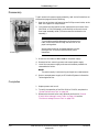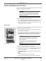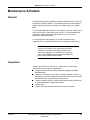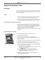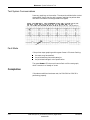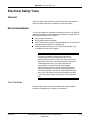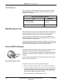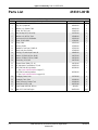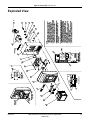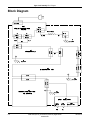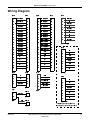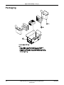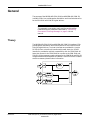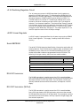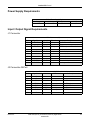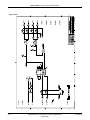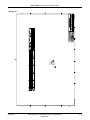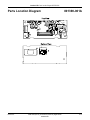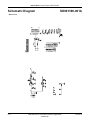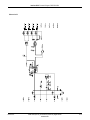
1
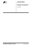
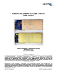
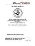
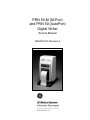
PRN 50-M (M-Port)
and PRN 50 (AutoPort)
Digital Writer
Service Manual
2006503-001 Revision A
127(
Due to continuing product innovation, specifications in this manual are subject to change without notice.
Trademarks
Listed below are GE Medical Systems Information Technologies trademarks. All other trademarks contained
herein are the property of their respective owners.
900 SC, ACCUSKETCH, AccuVision, APEX, AQUA-KNOT, ARCHIVIST, Autoseq, BABY MAC, C Qwik
Connect, CardioServ, CardioSmart, CardioSys, CardioWindow, CASE, CD TELEMETRY, CENTRA, CHART
GUARD, CINE 35, CORO, COROLAN, COROMETRICS, Corometrics Sensor Tip, CRG PLUS, DASH,
Digistore, Digital DATAQ, E for M, EAGLE, Event-Link, FMS 101B, FMS 111, HELLIGE, IMAGE STORE,
INTELLIMOTION, IQA, LASER SXP, MAC, MAC-LAB, MACTRODE, MANAGED USE, MARQUETTE,
MARQUETTE MAC, MARQUETTE MEDICAL SYSTEMS, MARQUETTE UNITY NETWORK, MARS,
MAX, MEDITEL, MEI, MEI in the circle logo, MEMOPORT, MEMOPORT C, MINISTORE, MINNOWS,
Monarch 8000, MULTI-LINK, MULTISCRIPTOR, MUSE, MUSE CV, Neo-Trak, NEUROSCRIPT,
OnlineABG, OXYMONITOR, Pres-R-Cuff, PRESSURE-SCRIBE, QMI, QS, Quantitative Medicine,
Quantitative Sentinel, RAC RAMS, RSVP, SAM, SEER, SILVERTRACE, SOLAR, SOLARVIEW, Spectra
400, Spectra-Overview, Spectra-Tel, ST GUARD, TRAM, TRAM-NET, TRAM-RAC, TRAMSCOPE, TRIM
KNOB, Trimline, UNION STATION, UNITY logo, UNITY NETWORK, Vari-X, Vari-X Cardiomatic,
VariCath, VARIDEX, VAS, and Vision Care Filter are trademarks of GE Medical Systems Information
Technologies registered in the United States Patent and Trademark Office.
12SL, 15SL, Access, AccuSpeak, ADVANTAGE, BAM, BODYTRODE, Cardiomatic, CardioSpeak, CD
TELEMETRY®-LAN, CENTRALSCOPE, Corolation, EDIC, EK-Pro, Event-Link Cirrus, Event-Link
Cumulus, Event-Link Nimbus, HI-RES, ICMMS, IMAGE VAULT, IMPACT.wf, INTER-LEAD, IQA,
LIFEWATCH, Managed Use, MARQUETTE PRISM, MARQUETTE® RESPONDER, MENTOR, MicroSmart,
MMS, MRT, MUSE CardioWindow, NST PRO, NAUTILUS, O2SENSOR, Octanet, OMRS, PHi-Res,
Premium, Prism, QUIK CONNECT V, QUICK CONNECT, QT Guard, SMART-PAC, SMARTLOOK, Spiral
Lok, Sweetheart, UNITY, Universal, Waterfall, and Walkmom are trademarks of GE Medical Systems
Information Technologies.
© GE Medical Systems Information Technologies, 2001. All rights reserved.
T-2
PRN 50-M (M-Port) and PRN 50 (AutoPort) Digital Writer
2006503-001
Revision A
23 March 2001
Contents
1
Introduction . . . . . . . . . . . . . . . . . . . . . . . . . . . . . . . . . . . . 1-1
Manual Information . . . . . . . . . . . . . . . . . . . . . . . . . . . . . . . . . . . . . . . . . . . . . . . . . . 1-3
Revision History . . . . . . . . . . . . . . . . . . . . . . . . . . . . . . . . . . . . . . . . . . . . . . . . . . . 1-3
Purpose of Manual . . . . . . . . . . . . . . . . . . . . . . . . . . . . . . . . . . . . . . . . . . . . . . . . . 1-3
Safety Information . . . . . . . . . . . . . . . . . . . . . . . . . . . . . . . . . . . . . . . . . . . . . . . . . . . 1-4
Responsibility of the Manufacturer . . . . . . . . . . . . . . . . . . . . . . . . . . . . . . . . . . . . . 1-4
Intended Use . . . . . . . . . . . . . . . . . . . . . . . . . . . . . . . . . . . . . . . . . . . . . . . . . . . . . 1-4
Equipment Symbols . . . . . . . . . . . . . . . . . . . . . . . . . . . . . . . . . . . . . . . . . . . . . . . . 1-5
Warnings, Cautions, and Notes . . . . . . . . . . . . . . . . . . . . . . . . . . . . . . . . . . . . . . . 1-5
Service Information . . . . . . . . . . . . . . . . . . . . . . . . . . . . . . . . . . . . . . . . . . . . . . . . . . 1-6
Service Requirements . . . . . . . . . . . . . . . . . . . . . . . . . . . . . . . . . . . . . . . . . . . . . . 1-6
Equipment Identification . . . . . . . . . . . . . . . . . . . . . . . . . . . . . . . . . . . . . . . . . . . . . 1-6
Warranty . . . . . . . . . . . . . . . . . . . . . . . . . . . . . . . . . . . . . . . . . . . . . . . . . . . . . . . . 1-6
2
Equipment Overview . . . . . . . . . . . . . . . . . . . . . . . . . . . . . 2-1
Description of Equipment . . . . . . . . . . . . . . . . . . . . . . . . . . . . . . . . . . . . . . . . . . . . . 2-3
PRN 50-M and PRN 50 Digital Writers . . . . . . . . . . . . . . . . . . . . . . . . . . . . . . . . . 2-3
Controls . . . . . . . . . . . . . . . . . . . . . . . . . . . . . . . . . . . . . . . . . . . . . . . . . . . . . . . . . 2-4
Interconnection . . . . . . . . . . . . . . . . . . . . . . . . . . . . . . . . . . . . . . . . . . . . . . . . . . . 2-4
Mounting . . . . . . . . . . . . . . . . . . . . . . . . . . . . . . . . . . . . . . . . . . . . . . . . . . . . . . . . 2-8
Technical Specifications . . . . . . . . . . . . . . . . . . . . . . . . . . . . . . . . . . . . . . . . . . . . . . 2-9
Certification . . . . . . . . . . . . . . . . . . . . . . . . . . . . . . . . . . . . . . . . . . . . . . . . . . . . . 2-10
Classifications . . . . . . . . . . . . . . . . . . . . . . . . . . . . . . . . . . . . . . . . . . . . . . . . . . . 2-10
3
Troubleshooting . . . . . . . . . . . . . . . . . . . . . . . . . . . . . . . . 3-1
General . . . . . . . . . . . . . . . . . . . . . . . . . . . . . . . . . . . . . . . . . . . . . . . . . . . . . . . . . . . . 3-3
Troubleshooting the Components . . . . . . . . . . . . . . . . . . . . . . . . . . . . . . . . . . . . . 3-3
Controlling Electrostatic Discharge Damage . . . . . . . . . . . . . . . . . . . . . . . . . . . . . 3-4
Thermal Writer Replacement Procedure . . . . . . . . . . . . . . . . . . . . . . . . . . . . . . . . 3-6
Power Supply Replacement Procedure . . . . . . . . . . . . . . . . . . . . . . . . . . . . . . . . . 3-9
Interface PCB Replacement Procedure . . . . . . . . . . . . . . . . . . . . . . . . . . . . . . . . 3-11
Revision A
PRN 50-M (M-Port) and PRN 50 (AutoPort) Digital Writer
2006503-001
i
4
Maintenance . . . . . . . . . . . . . . . . . . . . . . . . . . . . . . . . . . . 4-1
Maintenance Schedule . . . . . . . . . . . . . . . . . . . . . . . . . . . . . . . . . . . . . . . . . . . . . . . 4-3
General . . . . . . . . . . . . . . . . . . . . . . . . . . . . . . . . . . . . . . . . . . . . . . . . . . . . . . . . . 4-3
Inspection . . . . . . . . . . . . . . . . . . . . . . . . . . . . . . . . . . . . . . . . . . . . . . . . . . . . . . . . 4-3
General Cleaning . . . . . . . . . . . . . . . . . . . . . . . . . . . . . . . . . . . . . . . . . . . . . . . . . . 4-4
Cleaning the Print Head . . . . . . . . . . . . . . . . . . . . . . . . . . . . . . . . . . . . . . . . . . . . . 4-5
Performance Test . . . . . . . . . . . . . . . . . . . . . . . . . . . . . . . . . . . . . . . . . . . . . . . . . 4-6
System Performance Test . . . . . . . . . . . . . . . . . . . . . . . . . . . . . . . . . . . . . . . . . . . . . 4-9
Procedure . . . . . . . . . . . . . . . . . . . . . . . . . . . . . . . . . . . . . . . . . . . . . . . . . . . . . . . 4-9
Completion . . . . . . . . . . . . . . . . . . . . . . . . . . . . . . . . . . . . . . . . . . . . . . . . . . . . . . 4-10
Electrical Safety Tests . . . . . . . . . . . . . . . . . . . . . . . . . . . . . . . . . . . . . . . . . . . . . . . 4-11
General . . . . . . . . . . . . . . . . . . . . . . . . . . . . . . . . . . . . . . . . . . . . . . . . . . . . . . . . 4-11
Recommendations . . . . . . . . . . . . . . . . . . . . . . . . . . . . . . . . . . . . . . . . . . . . . . . . 4-11
Wall Receptacle Test . . . . . . . . . . . . . . . . . . . . . . . . . . . . . . . . . . . . . . . . . . . . . . 4-12
Ground (Earth) Integrity . . . . . . . . . . . . . . . . . . . . . . . . . . . . . . . . . . . . . . . . . . . . 4-12
Ground (Earth) Wire Leakage Current Tests . . . . . . . . . . . . . . . . . . . . . . . . . . . . 4-14
Enclosure Leakage Current Test . . . . . . . . . . . . . . . . . . . . . . . . . . . . . . . . . . . . . 4-15
Test Completion . . . . . . . . . . . . . . . . . . . . . . . . . . . . . . . . . . . . . . . . . . . . . . . . . . 4-16
5
Upper Level Assembly . . . . . . . . . . . . . . . . . . . . . . . . . . . 5-1
General . . . . . . . . . . . . . . . . . . . . . . . . . . . . . . . . . . . . . . . . . . . . . . . . . . . . . . . . . . . . 5-3
Upper Level . . . . . . . . . . . . . . . . . . . . . . . . . . . . . . . . . . . . . . . . . . . . . . . . . . . . . . 5-3
Parts List 418331-001B . . . . . . . . . . . . . . . . . . . . . . . . . . . . . . . . . . . . . . . . . . . . . . . 5-4
Exploded View . . . . . . . . . . . . . . . . . . . . . . . . . . . . . . . . . . . . . . . . . . . . . . . . . . . . . . 5-5
Block Diagram . . . . . . . . . . . . . . . . . . . . . . . . . . . . . . . . . . . . . . . . . . . . . . . . . . . . . . 5-6
Wiring Diagram . . . . . . . . . . . . . . . . . . . . . . . . . . . . . . . . . . . . . . . . . . . . . . . . . . . . . 5-7
Packaging . . . . . . . . . . . . . . . . . . . . . . . . . . . . . . . . . . . . . . . . . . . . . . . . . . . . . . . . . . 5-8
ii
PRN 50-M (M-Port) and PRN 50 (AutoPort) Digital Writer
2006503-001
Revision A
6
Interface PCB . . . . . . . . . . . . . . . . . . . . . . . . . . . . . . . . . . . 6-1
General . . . . . . . . . . . . . . . . . . . . . . . . . . . . . . . . . . . . . . . . . . . . . . . . . . . . . . . . . . . . 6-3
Theory . . . . . . . . . . . . . . . . . . . . . . . . . . . . . . . . . . . . . . . . . . . . . . . . . . . . . . . . . . 6-3
Power Supply Requirements . . . . . . . . . . . . . . . . . . . . . . . . . . . . . . . . . . . . . . . . . 6-5
Input / Output Signal Requirements . . . . . . . . . . . . . . . . . . . . . . . . . . . . . . . . . . . . 6-5
Parts List 801390-002A . . . . . . . . . . . . . . . . . . . . . . . . . . . . . . . . . . . . . . . . . . . . . . . 6-7
Parts Location Diagram 801390-002A . . . . . . . . . . . . . . . . . . . . . . . . . . . . . . . . . . . 6-8
Schematic Diagram SD801390-002A . . . . . . . . . . . . . . . . . . . . . . . . . . . . . . . . . . . . 6-9
Parts List 801390-001A . . . . . . . . . . . . . . . . . . . . . . . . . . . . . . . . . . . . . . . . . . . . . . 6-12
Parts Location Diagram 801390-001A . . . . . . . . . . . . . . . . . . . . . . . . . . . . . . . . . . 6-13
Schematic Diagram SD801390-001A . . . . . . . . . . . . . . . . . . . . . . . . . . . . . . . . . . . 6-14
Revision A
PRN 50-M (M-Port) and PRN 50 (AutoPort) Digital Writer
2006503-001
iii
iv
PRN 50-M (M-Port) and PRN 50 (AutoPort) Digital Writer
2006503-001
Revision A
1
Revision A
Introduction
PRN 50-M (M-Port) and PRN 50 (AutoPort) Digital Writer
2006503-001
1-1
For your notes
1-2
PRN 50-M (M-Port) and PRN 50 (AutoPort) Digital Writer
2006503-001
Revision A
Introduction: Manual Information
Manual Information
Revision History
Each page of this manual has a revision letter located at the bottom of
the page. It identifies the revision level of the entire manual. This may be
important if you have more than one manual and you wish to know
which is the most current.
For the initial release, all pages have the revision letter A. For the
second update, all pages receive the revision letter B. The latest letter of
the alphabet added to the table below corresponds to the most current
revision.
Table 1. Revision History
Revision
Date
A
3/23/2001
Comment
Initial Release
Purpose of Manual
This Service Manual covers the use of both:
n
n
The PRN 50 writer with the M-Port interface (PRN 50-M) and
The PRN 50 writer with the AutoPort interface (PRN 50).
This manual provides technical information for service representatives
and technical personnel involved in configuring and maintaining the
PRN 50-M and the PRN 50 Digital Writers.
Revision A
PRN 50-M (M-Port) and PRN 50 (AutoPort) Digital Writer
2006503-001
1-3
Introduction: Safety Information
Safety Information
Responsibility of the Manufacturer
GE Medical Systems Information Technologies is responsible for the
effects of safety, reliability, and performance only if:
n
assembly operations, extensions, readjustments, modifications, or
repairs are carried out by persons authorized by GE Medical Systems
Information Technologies;
n
the electrical installation of the relevant room complies with the
requirements of the appropriate regulations; and
n
the device is used in accordance with the instructions for use.
Intended Use
Follow the directives stated below when using the PRN 50-M Digital
Writer.
n
This device is intended for use under the direct supervision of a
licensed health care practitioner.
n
n
This device is not intended for home use.
n
Contact GE Medical Systems Information Technologies for
information before connecting any device to the equipment that is
not recommended in this manual.
n
Parts and accessories used must meet the requirements of the
applicable IEC 601 series safety standards, and/or the system
configuration must meet the requirements of the IEC 60601-1-1
medical electrical systems standard.
n
Periodically, and whenever the integrity of the device is in doubt, test
all functions.
n
The use of ACCESSORY equipment not complying with the
equivalent safety requirements of this equipment may lead to a
reduced level of safety of the resulting system. Consideration
relating to the choice shall include:
Federal law restricts this device to be sold by or on the order of a
physician.
u use of the accessory in the PATIENT VICINITY; and
u evidence that the safety certification of the ACCESSORY has
been performed in accordance to the appropriate IEC 60601-1
and/or IEC 60601-1-1 harmonized national standard.
n
1-4
If the installation of the equipment, in the USA, will use 240V rather
than 120V, the source must be a center-tapped, 240V, single-phase
circuit.
PRN 50-M (M-Port) and PRN 50 (AutoPort) Digital Writer
2006503-001
Revision A
Introduction: Safety Information
Equipment Symbols
The following symbols appear on the transmitter.
ATTENTION: Consult accompanying documents before using the
equipment.
Equipotentiality
Alternating current (AC)
Power switch; I = ON; O = OFF.
Fuse
Warnings, Cautions, and Notes
Warnings and Cautions are used throughout this manual to designate a
degree or level of hazardous situations. Hazard is defined as a source of
potential injury to a person.
:$51,1*
A warning indicates a potential hazard or unsafe practice
which, if not avoided, could result in death or serious
injury.
&$87,21
A caution indicates a potential hazard or unsafe practice
which, if not avoided, could result in minor personal
injury or product/property damage.
127(
A note provides application tips or other useful information to assure
that you get the most from your equipment.
Revision A
PRN 50-M (M-Port) and PRN 50 (AutoPort) Digital Writer
2006503-001
1-5
Introduction: Service Information
Service Information
Service Requirements
Follow the service requirements listed below.
n
Refer equipment servicing to Information Technologies’ authorized
service personnel only.
n
Any unauthorized attempt to repair equipment under warranty voids
that warranty.
n
It is the user’s responsibility to report the need for service to GE
Medical Systems Information Technologies or to one of their
authorized agents.
n
Failure on the part of the responsible individual, hospital, or
institution using this equipment to implement a satisfactory
maintenance schedule may cause undue equipment failure and
possible health hazards.
n
Regular maintenance, irrespective of usage, is essential to ensure
that the equipment will always be functional when required.
Equipment Identification
Every GE Medical Systems Information Technologies device has a
unique serial number for identification. The serial number appears on
the product label for each unit.
D 1 XX 0005 G XX
Month
Manufactured
A = January
B = February
C = March
D = April
E = May
F = June
G = July
H = August
J = September
K = October
L = November
M = December
Year
Manufactured
1 = 2001
2 = 2002
3 = 2003
(and so on)
Product Code
Two-character
product descriptor
Product Sequence
Division
Number
F = Cardiology
Manufacturing
number (of total G = Monitoring
J = G. W. Labs
units
manufactured.)
Device Characteristics
One or 2 letters that further
describe the unit, for example:
P = prototype not conforming to
marketing specification
R = refurbished equipment
S = special product documented
under Specials part numbers
U = upgraded unit
Warranty
1 year.
1-6
PRN 50-M (M-Port) and PRN 50 (AutoPort) Digital Writer
2006503-001
Revision A
2
Revision A
Equipment Overview
PRN 50-M (M-Port) and PRN 50 (AutoPort) Digital Writer
2006503-001
2-1
For your notes
2-2
PRN 50-M (M-Port) and PRN 50 (AutoPort) Digital Writer
2006503-001
Revision A
Equipment Overview: Description of Equipment
Description of Equipment
PRN 50-M and PRN 50 Digital Writers
The PRN 50-M and PRN 50 Digital Writers thermally record patient
data on a paper strip. You can graph any parameter or trace you monitor
on a Solar 7000/8000/8000M monitor, Eagle 4000 monitor, Centralscope,
or CIC system on the the writer. Graphs are initiated automatically
when an alarm activates, or you can manually initiate a graph from a
monitor.
The writer provides a high-resolution recording of patient waveform
data, including alphanumeric text relating to the waveform data. A
microprocessor-driven thermal print head translates digitized data
directly into graphic forms on the strip chart. Up to four real-time
waveforms from the monitor screen may be graphed simultaneously. The
writer also generates printouts of stored information, including trended
parameters, arrhythmia information, and cardiac calculations,
pulmonary calculations, and dose calculations.
The paper drive motor is the only moving part on the PRN 50-M. This
motor operates at eight different speeds—0.1, 0.5, 1, 5, 10, 12.5, 25, and
50 mm/s.
g
PRN 50-M and PRN 50 Digital Writer
Revision A
PRN 50-M (M-Port) and PRN 50 (AutoPort) Digital Writer
2006503-001
2-3
Equipment Overview: Description of Equipment
Controls
A 32:(5 indicator illuminates when power is applied and a 3$3(5
287 indicator illuminates when you need to add paper or the paper
carriage door is open. If you press the *5$3+6723 switch while
graphing, the writer stops immediately. If you hold the switch down for
more than 10 seconds, an alphanumeric test strip prints out.
32:(5 Indicator
g
3$3(5287
Indicator
*5$3+6723Button
Front Panel Controls
Interconnection
M-Port/AutoPort Compatibility
1. An M-Port Host/Device must be connected to an M-port Device/Host.
2. If an AutoPort Host/Device is to be connected to an M-Port Device/
Host, the AutoPort Host/Device must be adapted to an M-Port pin
out by using the AutoPort to M-Port Adapter.
127(
Whether a host or device implements an M-Port or an AutoPort
interface can be determined by:
1. M-Port Host/Device products have any or all of the following:
a. Have the word ‘M-Port’ or ‘M#’ e.g., ‘M1’, ‘M2’, ‘M3’; for
the connector name on the label above the RJ-45.
b. Have the text for the name of the RJ-45 connector in a
yellow field.
c. Have a product name that ends in an ‘M’, e.g., Solar
8000M, PRN 50-M, Respiratory Mechanics-M.
2. AutoPort Host/Device products do not have any of the above.
2-4
PRN 50-M (M-Port) and PRN 50 (AutoPort) Digital Writer
2006503-001
Revision A
Equipment Overview: Description of Equipment
Device Connections
Below are figures of device connections using the Octanet connectivity
device and using the Tram-net Interface Adapter. Refer to “Connection of
a PRN 50-M/PRN 50 to a:” on page 2-7 for connection instructions.
M-Port connector
on RM-M
M-Port connector
(cardiac package)
M-Port connectors
(basic software package)
8000M M-Ports
RM-M Module Connected to Patient Monitor via Octanet Connectivity
Device with M-Port to AutoPort Adapter
COM2 Serial Port
(DB9M Serial Port)
CIC to PRN 50-M
Revision A
PRN 50-M (M-Port) and PRN 50 (AutoPort) Digital Writer
2006503-001
2-5
RS-232
RMT ALM
TRAM-NET
ETHERNET
RMT VID
ASYNC COMM
Equipment Overview: Description of Equipment
Solar 8000 to PRN 50-M ASYNC Port
Table 2. Host to PRN 50-M/PRN 50 Connections.
Hosting Device
Monitor/Octanet/
Central Station
Solar 8000M
Octanet
CIC
Eagle 3000
Eagle 4000
Solar 7000
Solar 8000
Tramscope
Centralscope
Connector
Used
RJ-45
M1.. M4
(M-Ports)
PRN 50-M/PRN 50
Type
Connector Protocol
Used
(Note #1)
Interconnection Between Host and Writer
Adapter
Needed?
Part #
Where Placed
Cable Used
PRN 50-M RJ-45
M-Port
No
PRN 50
AutoPort
Yes
2001973-001 PRN 50
PRN 50-M RJ-45
M-Port
Yes
2001973-001 Octanet
PRN 50
AutoPort
No
DB9M Serial PRN 50-M RJ-45
Port
PRN 50
RJ-45
M-Port
Yes
AutoPort
No
422843-00x
DB9F Async Either
DB9M
PRN 50-M
or PRN 50
Async
No
700179-00x
RJ-45
(AutoPorts)
RJ-45
RJ-45
418335-00x
418335-00x
418335-00x
418335-00x
2006550-001 CIC
418335-00x
127(
The RJ-45 connector protocol is specified on the label below the RJ45 Connector (i.e, 03RUW or $XWR3RUW).
Power Switch
AC Power Cable
Connector
M-Port or AutoPort
Power Cable
Clamp
Async Comm
Serial Number
Back Panel
2-6
PRN 50-M (M-Port) and PRN 50 (AutoPort) Digital Writer
2006503-001
Revision A
Equipment Overview: Description of Equipment
Table 3. Adapter/Cable References for Table 4
Cable or Adapter
AutoPort to M-Port Adapter
Part Number
GEMS-IT #2001973-001
RJ-45 Cable
GEMS-IT #418335-00x
CIC(DB9F) to PRN 50-M (RJ-45) Adapter
GEMS-IT #2006550-001
Female DB9 TO Male RJ45 Cable
GEMS-IT #422843-00x
Scope DB9M/DB9F Cable
GEMS-IT #700179-00x
Table 4. Connection of a PRN 50-M/PRN 50 to a:
Monitor/Host:
Instructions:
Solar 8000M:
With the PRN 50-M writer (which has the M-Port
interface):
1. Connect one end of an RJ-45 cable into the RJ-45
connector on the PRN 50-M labeled ‘M-Port’.
2. Connect the other end of the cable into any available MPort RJ-45 connectors on the front of the Solar 8000M
labeled ‘M1,’ ‘M2,’ ‘M3,’ or ‘M4.’
3. Make sure that all components have power on.
4. Make selections desired using the Graph menu options.
With the PRN 50 writer (which has the AutoPort interface): 1. Place an AutoPort to M-Port Adapter into the RJ-45
connector on the PRN 50 labeled ‘AutoPort’.
2. Connect one end of an RJ-45 cable into the RJ-45
connector in the AutoPort to M-Port Adapter which was
inserted into the PRN 50 connector labeled ‘AutoPort’ in
step #1.
3. Connect the other end of the cable into any available
RJ-45 connectors, M-Ports on the front of the Solar
8000M labeled ‘M1’, ‘M2’, ‘M3’ or ‘M4’.
4. Make sure that all components have power on.
5. Make selections desired using the Graph menu options.
Octanet Connectivity Device:
With the PRN 50-M writer (which has the M-Port
interface):
1. Place an AutoPort to M-Port Adapter into one of the RJ45 connectors (AutoPorts) on the front of the Octanet.
Connectivity Device.
2. Connect one end of an RJ-45 cable into the RJ-45
connector on the PRN 50-M labeled ‘M-Port’.
3. Connect the other end of the RJ-45 cable into the
AutoPort to M-Port Adapter inserted into the Octanet
Connectivity Device RJ-45 in Step #1
4. Make sure that all components have power on.
5. Make selections desired using the Graph menu options.
With the PRN 50 writer (which has the AutoPort interface): 1. Connect one end of the RJ-45 cable into the RJ-45
connector in the PRN 50 connector labeled ‘AutoPort’.
2. Connect the other end of the RJ-45 cable into any
available RJ-45 connectors (AutoPorts) on the front of
the Octanet Connectivity Device.
3. Make sure that all components have power on.
4. Make selections desired using the Graph menu options.
Revision A
PRN 50-M (M-Port) and PRN 50 (AutoPort) Digital Writer
2006503-001
2-7
Equipment Overview: Description of Equipment
Table 4. Connection of a PRN 50-M/PRN 50 to a:
Monitor/Host:
Instructions:
CIC:
With the PRN 50-M writer (which has the M-Port
interface):
1. Place an CIC(DB9F) to PRN 50-M (RJ-45) Adapter on
the DB9M serial port connector of the CIC.
2. Connect one end of an RJ-45 cable into the RJ-45
connector on the PRN 50-M labeled ‘M-Port’.
3. Connect the other end of the RJ-45 cable into the RJ-45
connector in the adapter attached to the CIC in Step #1
4. Make sure that all components have power on.
5. Make selections desired using the Graph menu options.
With the PRN 50 writer (which has the AutoPort interface): 1. Connect the RJ-45 end of the FEMALE DB9 TO MALE
RJ45 cable into the RJ-45 connector in the PRN 50
connector labeled ‘AutoPort’.
2. Connect the other end of the FEMALE DB9 TO MALE
RJ45 cable to the DB9M serial port connector of the
CIC.
3. Make sure that all components have power on.
4. Make selections desired using the Graph menu options.
Eagle 3000, Eagle 4000, Solar 7000, Solar 8000, Tramscope, Centralscope:
With the PRN 50-M (which has the M-Port interface) or
the PRN 50 writer (which has the AutoPort interface):
2-8
1. Connect the DB9F end of the Scope DB9M/DB9F cable
into the DB9M connector in the PRN 50-M/PRN 50
connector labeled ‘Async Comm’.
2. Connect the other end of the Scope DB9M/DB9F cable
to the DB9F ‘Async Comm’ serial port connector of the
Eagle 3000, Eagle 4000, Solar 7000, Solar 8000,
Tramscope or Centralscope.
3. Make sure that all components have power on.
4. Make selections desired using the Graph menu options.
PRN 50-M (M-Port) and PRN 50 (AutoPort) Digital Writer
2006503-001
Revision A
Equipment Overview: Description of Equipment
Mounting
You must use the PRN 50-M or PRN 50 with an optional pedestal base
(shown below) or with an optional mounting bracket. See the GE Medical
Systems Information Technologies Monitoring Systems Mounting
Reference Guide (pn 403799-010) for detailed information.
&$87,21
Do NOT operate the device without an approved mount
attached. The operational temperature of this device is
maintained by air flow though the bottom vent holes.
PRN 50-M or PRN 50 with Pedestal
Revision A
PRN 50-M (M-Port) and PRN 50 (AutoPort) Digital Writer
2006503-001
2-9
Equipment Overview: Technical Specifications
Technical Specifications
Table 5. Performance Specifications
Display Indicators (LEDs)
System Interface
Number of Waveform Channels
Recorder Information
Writing Method
Writing Resolution
Power, Paper Out
May be used with any Solar monitor, Eagle monitor, or Tram display.
Four maximum
Automatic graphing from alarm or alarm stacking, manual graphing from monitor or central station
display.
Thermal, fixed head, dot array.
200 dots/inch vertical, 480 dots/inch horizontal at 25 mm/s.
Paper Width
50 mm (1.97 in)
Paper Length
30.5 m (100 ft.)
Paper Speed
0.1, 0.5, 1, 5, 10, 12.5, 25, 50 mm/s (±2%)
Waveform Frequency Response
Grid
Limited only by acquisition system.
Printed as needed.
Table 6. Environmental Specifications
Power Requirements
110 ±20 VAC, 50/60 Hz, single phase 220 ±40 VAC, 50/60 Hz, single phase
Power Consumption
50 W maximum
Cooling
Convection
Heat Dissipation
170 Btu/hr
Operating
Storage
Ambient temperature: 0° C to 50° C (32° F to 122° F)
Relative humidity: 5% to 95% (noncondensing).
Ambient temperature: –40° C to 70° C (–40° F to 158° F)
Relative humidity: 5% to 95% (noncondensing).
Table 7. Physical Specifications
Height
20.4 cm (8 in)
Width
11.6 cm (4.6 in)
Depth
9.3 cm (3.7 in)
Net Weight
Mounting
2-10
2.6 kg (5.7 lb) with base 1.2 kg (2.7 lb) without base
Free-standing when used with optional pedestal base. Optional wall mount also available.
PRN 50-M (M-Port) and PRN 50 (AutoPort) Digital Writer
2006503-001
Revision A
Equipment Overview: Technical Specifications
Certification
Safety standards
UL Classified for 2601-1
UL Classified for CAN/CSA C22.2 No. 601.1
IEC 60601-1 Certified
CE Marking for the 93/42/EEC Medical Device Directive
Classifications
Equipment components are classified, according to IEC-60601-1, as:
Type of protection against
electrical shock
Degree of protection against
electrical shock
Degree of protection against
harmful ingress of water
Degree of safety of application
in the presence of a flammable
anesthetic mixture with air or
with oxygen or nitrous oxide
Method(s) of sterilization or
disinfection recommended by
the manufacturer
Mode of operation
Table 8. Product Classifications
PRN 50-M
I
Not Marked
Ordinary
Not Suitable
NA
Continuous
PRN 50
I
Not Marked
Ordinary
Not Suitable
NA
Continuous
Key:
I: Class I equipment
B: Type B equipment
BF: Type BF equipment
CF: Type CF equipment
NA: Not applicable
Ordinary: Ordinary equipment (enclosed equipment without
protection against ingress of water)
Not Suitable: Equipment not suitable for use in the presence of a
flammable anesthetic mixture with air or with oxygen or nitrous
oxide
Underwriters Laboratories, Inc.
Classified by Underwriters Laboratories Inc. with respect
to electric shock, fire, mechanical and other specified
hazards, only in accordance with UL 2601-1, CAN/CSA
C22.2 No. 601.1, IEC 60601-1, and, if required, IEC 606012-27, IEC 60601-2-30, IEC 60601-2-34, IEC 60601-1-1.
Revision A
PRN 50-M (M-Port) and PRN 50 (AutoPort) Digital Writer
2006503-001
2-11
Equipment Overview: Technical Specifications
For your notes
2-12
PRN 50-M (M-Port) and PRN 50 (AutoPort) Digital Writer
2006503-001
Revision A
3
Revision A
Troubleshooting
PRN 50-M (M-Port) and PRN 50 (AutoPort) Digital Writer
2006503-001
3-1
For your notes
3-2
PRN 50-M (M-Port) and PRN 50 (AutoPort) Digital Writer
2006503-001
Revision A
Troubleshooting: General
General
Troubleshooting the Components
This section contains information that may be useful when you
troubleshoot the PRN 50-M and PRN 50 Digital Writers.
Visual Inspection
This visual inspection procedure looks for obvious problems in the
equipment. Simple failures–disconnected cables, foreign debris on a
printed circuit board, or even missing hardware–can seriously affect the
operation.
These simple failures can appear to be completely different problems to
the user, or repair technician, making the troubleshooting process very
difficult.
The following steps might seem trivial but we highly recommended that
you perform them to remove these “simple” failures as causes of
problems in the equipment.
Revision A
n
Never turn off host equipment by pulling the power cord out of the
wall receptacle. Always use the power switch to apply/remove power.
Always verify that the power switch is in the 2)) position before
removing the power cord from the wall receptacle. Set the power
switch to the 2)) position and disconnect the equipment from its
power source.
n
Check all power and interface cables to make sure they are firmly
connected. There should be no excessive tension on any of the cables
nor should any of them be showing any signs of excessive wear.
n
Check rear connector of the module for foreign debris or crushed
connections.
n
Check the power cord on the host equipment. Verify that the line,
neutral and ground wires are all connected firmly to the plug and
that they are not shorted together. See wall receptacle check found in
Electrical Safety Tests of the appropriate patient monitor service
manual.
PRN 50-M (M-Port) and PRN 50 (AutoPort) Digital Writer
2006503-001
3-3
Troubleshooting: General
Controlling Electrostatic Discharge Damage
All external connector inputs and outputs of the device are designed with
protection from ESD damage. However, if the device requires service,
exposed components and assemblies contained within are susceptible to
ESD damage. This includes human hands, non-ESD protected work
stations and/or improperly grounded test equipment.
The following guidelines will help make a service workstation more
resistant to the ESD damage:
n
Discharge any static charge you may have built up before handling
semiconductors or assemblies containing semiconductors.
n
A grounded, antistatic wristband (3M part number 2046 or
equivalent) or heel strap should be worn at all times while handling
or repairing assemblies containing semiconductors.
n
n
Use properly grounded soldering and test equipment.
n
Do not remove semiconductors or assemblies containing
semiconductors from antistatic containers (Velo-stat bags) until
absolutely necessary.
n
Make sure power to an assembly is turned off before removing or
inserting a semiconductor.
n
Do not slide semiconductors or electrical/electronic assemblies across
any surface.
n
n
Do not touch semiconductor leads unless absolutely necessary.
Use a static-free work surface (3M part number 8210 or equivalent)
while handling or working on assemblies containing semiconductors.
Semiconductors and electrical/electronic assemblies should be stored
only in antistatic bags or boxes.
These guidelines may not guaranty a 100% static-free workstation, but
will greatly reduce the potential for failure of any electrical/electronic
assemblies.
3-4
PRN 50-M (M-Port) and PRN 50 (AutoPort) Digital Writer
2006503-001
Revision A
Troubleshooting: General
Fuse Replacement
The fuse drawer on the PRN 50-M contains two metric fuses
(pn 409801-003). Follow these steps to replace the fuses.
1. Place the power switch on the power-entry module in the 2))
position.
2. Remove the power cord from the mains power source and the powerentry module.
3. Use a small screwdriver to release the power-entry module door and
loosen the fuse holder block from the power-entry module.
O
I
4. Remove the fuse holder block, replace the defective fuse(s) and
reassemble.
Revision A
PRN 50-M (M-Port) and PRN 50 (AutoPort) Digital Writer
2006503-001
3-5
Troubleshooting: General
Thermal Writer Replacement Procedure
This procedure details the removal and replacement of the thermal
writer assembly in the PRN 50-M and PRN 50.
127(
To control static-discharge damage, be sure to discharge any static
charge you may have built up before starting this procedure. Wear a
grounded, antistatic strap and use grounded test equipment.
This procedure should be performed in the order listed.
1. Turn the 212)) switch at back to 2)) position. Always use the
212)) switch to apply power. Remove power cord from unit.
2. Disconnect the PRN 50-M or PRN 50 from the patient monitor and
communication network, if applicable.
Disassembly
To remove the thermal writer assembly, refer to “Writer Replacement
Illustrations” on page 3-8 and do the following.
1. Open the writer door and locate the two Phillips screws inside, at the
back of the paper roll compartment.
2. Fully loosen the two captive screws and separate the two halves of
the PRN 50-M or PRN 50 assembly. (The two screws remain in the
assembly.)
&$87,216
To avoid doing possible damage to the thermal print
head, access the screws through the two slots in the
paper carriage door.
Always hold the writer and bezel together to avoid
putting strain on the flex cable and front panel
membrane.
3. Lift up on the flex cable connector latch and disconnect the flex cable
from the back of the writer.
4. Pull the writer straight forward from the front bezel.
5. Return removed 2-inch thermal writer to GE Medical Systems
Information Technologies.
3-6
PRN 50-M (M-Port) and PRN 50 (AutoPort) Digital Writer
2006503-001
Revision A
Troubleshooting: General
Reassembly
To replace the thermal writer assembly, refer to “Writer Replacement
Illustrations” on page 3-8 and do the following.
1. Slide the new thermal writer straight into the front bezel.
2. Feed the flex cable through the opening in the PCB and press the
release latch on the flex connector to lock the cable in place.
3. Slightly tug on the flex cable to confirm that the connector has
latched.
4. Carefully slide the two halves of the PRN 50-M or PRN 50 back
together, open the paper carriage door and tighten the two screws.
&$87,21
Do NOT overtighten the screws. Overtightening the
screws could cause damage to the PRN 50-M or PRN 50.
Revision A
PRN 50-M (M-Port) and PRN 50 (AutoPort) Digital Writer
2006503-001
3-7
Troubleshooting: General
Writer Replacement Illustrations
Loosen the Screws
Separate the Assembly
Incorrect
Correct
3-8
Inside Front Bezel
Unlock the Flex Cable
Remove & Replace the
Writer
Reattch the Flex Cable
Remove the Flex Cable
Lock the Flex Cable
PRN 50-M (M-Port) and PRN 50 (AutoPort) Digital Writer
2006503-001
Revision A
Troubleshooting: General
5. Thread the mounting screw completely through the ESD shield as
shown below before sliding the two halves of the PRN 50-M or PRN
50 back together.
Correct
ESD Shield View
Incorrect
6. Carefully slide the two halves of the PRN 50-M or PRN 50 back
together, open the paper carriage door and tighten the two mounting
screws
Completion
1. Reattach the power cord to the unit.
2. To verify the operation of the PRN 50-M or PRN 50, complete the
“System Performance Test” on page 4-9.
3. Because the thermal writer was replaced, perform the “Ground
(Earth) Wire Leakage Current Tests” on page 4-14 and the
“Enclosure Leakage Current Test” on page 4-15.
Power Supply Replacement Procedure
This procedure details the removal and replacement of the power supply
assembly in the PRN 50-M and PRN 50.
&$87,21
To control static-discharge damage, be sure to discharge
any static charge you may have built up before starting
procedure. Wear a grounded, antistatic strap and use
grounded test equipment.
This procedure should be performed in the order listed.
1. Turn the ON/OFF (,2) switch OFF (2). Always use the ON/OFF
(,2) switch to apply power. Remove the power cord from the unit.
2. Disconnect the PRN 50-M or PRN 50 from the patient monitor and
communication network, if applicable.
Revision A
PRN 50-M (M-Port) and PRN 50 (AutoPort) Digital Writer
2006503-001
3-9
Troubleshooting: General
Disassembly
J1
J2
To gain access to the power supply assembly, refer to the illustrations on
the previous page and do the following:
1. Open the writer door and locate the two Phillips screws inside, at the
back of the paper roll compartment.
2. Fully loosen the two captive screws, separate the two halves of the
PRN 50-M or PRN 50 assembly, and carefully set the writer and
front bezel assembly aside. (The two screws are retained in the
assembly.)
&$87,216
To avoid doing possible damage to the thermal print
head, access the screws through the two slots in the
paper carriage door.
Power Supply
Always hold the writer and bezel together to avoid
putting strain on the flex cable and front panel
membrane.
3. Disconnect the cables at - and - on the power supply.
4. Remove the four mounting screws and remove power supply.
5. Install the new power supply and reverse the above procedure to
reassemble the writer.
127(
The power supply is auto sensing and requires no adjustments.
6. Return removed power supply to GE Medical Systems Information
Technologies Service.
Completion
1. Replace power cord to unit.
2. To verify the operation of the PRN 50-M or PRN 50, complete the
“System Performance Test” on page 4-9.
3. Because the thermal writer was replaced, perform the “Ground
(Earth) Wire Leakage Current Tests” on page 4-14 and the
“Enclosure Leakage Current Test” on page 4-15.
3-10
PRN 50-M (M-Port) and PRN 50 (AutoPort) Digital Writer
2006503-001
Revision A
Troubleshooting: General
Interface PCB Replacement Procedure
This procedure details the removal and replacement of the Interface PCB
assembly in the PRN 50-M and PRN 50.
&$87,21
To control static-discharge damage, be sure to discharge
any static charge you may have built up before starting
procedure. Wear a grounded, antistatic strap and use
grounded test equipment.
Perform this procedure in the order listed.
1. Turn the ON/OFF (,2) switch at back OFF (2). Always use the ON/
OFF switch to apply power. Remove the power cord from unit.
2. Disconnect the PRN 50-M or PRN 50 from the patient monitor and
communication network, if applicable.
Disassembly
To gain access to the power supply assembly, refer to the illustrations on
the previous page and do the following.
1. Open the writer door and locate the two Phillips screws inside, at
back of paper roll compartment.
2. Fully loosen the two captive screws, separate the two halves of the
PRN 50 assembly and carefully set the writer and front bezel
assembly aside. (The two screws are retained in the assembly.)
J1
&$87,216
To avoid doing possible damage to the thermal print
head, access the screws through the two slots in the
paper carriage door.
Interface PCB
Always hold the writer and bezel together to avoid
putting strain on the flex cable and front panel
membrane.
3. Disconnect the cable at - on the Interface PCB.
4. Remove the three mounting screws and remove the Interface PCB.
5. Remove the two jackscrews from the$V\QF&RPP connector on
the back of the assembly.
6. Install the new Interface PCB and reverse the above procedure to
reassemble the writer.
127(
The Interface PCB requires no adjustments.
7. Return the removed Interface PCB to Information Technologies.
Revision A
PRN 50-M (M-Port) and PRN 50 (AutoPort) Digital Writer
2006503-001
3-11
Troubleshooting: General
Completion
1. Replace power cord to unit.
2. To verify the operation of the PRN 50-M or PRN 50, complete the
“System Performance Test” on page 4-9.
3. Because the thermal writer was replaced, perform the “Ground
(Earth) Wire Leakage Current Tests” on page 4-14 and the
“Enclosure Leakage Current Test” on page 4-15.
3-12
PRN 50-M (M-Port) and PRN 50 (AutoPort) Digital Writer
2006503-001
Revision A
4
Revision A
Maintenance
PRN 50-M (M-Port) and PRN 50 (AutoPort) Digital Writer
2006503-001
4-1
Maintenance:
For your notes
4-2
PRN 50-M (M-Port) and PRN 50 (AutoPort) Digital Writer
2006503-001
Revision A
Maintenance: Maintenance Schedule
Maintenance Schedule
General
An effective maintenance schedule should be established for the PRN 50M and PRN 50 Digital Writers. The schedule should include inspection,
general cleaning, performance testing, and safety testing on a regular
basis.
It is recommended that you perform the inspection, general cleaning, and
cleaning of the print head every three months. It is recommended that
you perform safety tests every twelve months or if any internal
components have been altered.
For the purpose of record keeping, a “Preventive Maintenance
Inspection” form is provided at the end of this chapter for duplication.
:$51,1*
A failure, on the part of the responsible individual
hospital or institution employing the uses of this
monitoring equipment, to implement a satisfactory
maintenance schedule may cause undue equipment
failure and possible health hazards.
Inspection
Inspect the PRN 50-M or PRN 50 on a regular basis. Follow these
guideline when you inspect the equipment.
Revision A
n
Inspect the equipment for obvious physical damage and replace
damaged items.
n
Inspect all connectors for bent pins or prongs. Replace or repair any
bad cables or connectors. Note that replacement of connectors should
be performed only by qualified service personnel.
n
Inspect all cable insulation. Qualified service personnel should repair
or replace damaged or deteriorated cables.
n
n
Inspect fuses.
Inspect seating of socketed components and circuit boards.
PRN 50-M (M-Port) and PRN 50 (AutoPort) Digital Writer
2006503-001
4-3
Maintenance: Maintenance Schedule
General Cleaning
Exterior Cleaning
Clean the PRN 50-M or PRN 50 on a regular basis.
You may clean the exterior surfaces of the writer with a dampened lintfree cloth. Use one of the following approved solutions:
n
n
n
n
ammonia (diluted),
Cidex,
sodium hypochlorite bleach (diluted), or
mild soap (diluted).
To avoid damage to the equipment, follow these rules.
&$87,21
Failure to follow these rules may melt, distort, or dull the
finish of the case, blur lettering on the labels, or cause
equipment failures.
Always dilute the solutions according to the manufacturer’s suggestions.
Always wipe off all the cleaning solutions with a dry cloth after cleaning.
Never use wax containing a cleaning substance.
Never pour water or any cleaning solution on the equipment or permit
fluids to run behind switches, into the connectors, or into any ventilation
openings in the equipment.
Never use these cleaning agents:
n
n
n
abrasive cleaners or solvents of any kind,
n
Betadine.
acetone,
alcohol based cleaning agents (except for cleaning the thermal print
head), or
Interior Cleaning
On a regular basis, qualified service personnel should open the writer
and blow dust from the unit with compressed air.
4-4
PRN 50-M (M-Port) and PRN 50 (AutoPort) Digital Writer
2006503-001
Revision A
Maintenance: Maintenance Schedule
Cleaning the Print Head
This procedure explains how to clean the thermal print head. From
heavy usage, debris accumulates on the thermal print head and distorts
the printed image. It is recommended that you perform this procedure
when necessary, depending on usage.
Materials Required
A nonabrasive material/cloth and isopropyl alcohol are all that are
necessary to perform this procedure.
Procedure
Printhead
Perform this procedure in the order listed.
1. Turn the ,2switch at the back of the unit to the 2 (off) position and
disconnect the power cord from the mains source.
2. Open the writer door to expose the print head.
3. Remove paper roll.
4. Locate the print head (shown in the figure at the left). A flashlight
may help illuminate the print head for closer examination.
5. Wipe the print head with alcohol and a nonabrasive material/cotton
swab in a side to side motion. Continue wiping until the cloth/swab
wipes clean.
Paper Drive Roller
6. Wipe paper drive roller clean of any bits of paper and debris with
alcohol and a nonabrasive material.
Completion
Perform the “System Performance Test” on page 4-9 to verify PRN 50-M
and PRN 50 operation.
Revision A
PRN 50-M (M-Port) and PRN 50 (AutoPort) Digital Writer
2006503-001
4-5
Maintenance: Maintenance Schedule
Performance Test
This chapter contains a procedure for testing the performance of the PRN
50-M and the PRN 50 Digital Writers. Some familiarity with the PRN
50-M and the PRN 50 Digital Writers is required for this procedure.
Frequency
Perform this procedure every three months or whenever a circuit board
or other assembly is repaired or replaced.
Requirements
Connect the PRN 50-M or PRN 50 to a patient monitoring system to
complete the following steps.
127(
Before plugging the PRN 50-M or PRN 50 power cord into a power
receptacle, verify that the ,2 power switch is OFF (2). Always use
the power switch on the back to apply power.
1. Turn the PRN 50-M or PRN 50 power switch on the back panel ON
(,). The DC motor should not “jerk” the paper and nothing should
print on the paper.
2. Verify the 32:(5 indicator (green LED) on the front panel
illuminates.
3. Observe the 3$3(5287 indicator (yellow LED) on the front panel
does not illuminate.
If there is paper in the paper compartment, the LED should
illuminate briefly at start-up and then extinguish.
If there is no paper in the paper compartment, load paper in the
thermal writer. Press the *5$3+6723 button to aid in loading the
paper.
4. Press and hold the *5$3+6723 button for at least 10 seconds.
The writer should print out the revision of operating software
currently installed on the processor PCB with the alphanumeric test
pattern shown below.
Verify that the alphanumerics print clearly and are uniform in size
and contrast. If the printing is not uniform, clean the printhead and
try again. If the printer still fails, call GE Medical Systems
Information Technologies for service.
4-6
PRN 50-M (M-Port) and PRN 50 (AutoPort) Digital Writer
2006503-001
Revision A
Maintenance: Maintenance Schedule
Print Quality
After the alphanumerics print, continue to hold the *5$3+6723
button until the first test pattern is visible, then release. A series of three
test patterns follow to allow you to check the print quality.
To stop the test pattern at any time cycle the power by turning the power
switch off and then back on. Pressing the *5$3+6723 button while
the test pattern is running only changes the paper speed.
First Test Pattern
The first test pattern is used to check the roller for flat spots and other
irregularities. With this test the pattern you should see a uniform gray
background with no light spots or gaps. Check the roller for dirt or
damage if this test fails.
Text
At the start of each test pattern are printed seven lines of text. Verify
that all text and patterns are satisfactory as follows:
First and second lines – The first two lines consist of a GE Medical
Systems Information Technologies’ part number, software revision,
and date for the Boot and Main software.
Third line – Printed on the third line is the measured printhead
voltage.
Printhead
Resistance
Label
Forth line – The forth line shows the measured printhead temperature
in degrees centigrade. This temperature varies between 20 and 50
degrees and depends on the ambient temperature and what is
printing.
Fifth line – The fifth line is the printhead resistance range. The exact
printhead resistance range of your writer is printed on a label affixed
to the printhead which you can view by opening the paper carriage
door as shown in the drawing at the left. The resistance value
printed on this label should be within the range printed on the fifth
line.
Sixth line – Printed on the sixth line is the speed the test patterns are
printing.
Seventh line – Printed on the seventh line is the duty cycle of percent of
time the drive motor is on.
Revision A
PRN 50-M (M-Port) and PRN 50 (AutoPort) Digital Writer
2006503-001
4-7
Maintenance: Maintenance Schedule
Second Test Pattern
The second test pattern is used for checking printhead alignment, speed
accuracy, and speed regulation.
Printhead alignment – The two end most elements on the printhead
are turned on to form continuous lines on the edges of the paper.
These lines should always be visible. A light or missing line is an
indication of possible misalignment.
Speed accuracy – The grid pattern is printed to show speed control
accuracy. A marker at 75mm intervals along the bottom of the strip
is used for checking accuracy. To verify accuracy, place a 300mm
ruler on the first 75mm marker. The fifth 75mm marker should be at
300mm ± 6mm
Speed regulation – The triangular pattern is used to quickly check
speed regulation. The lines forming the triangle should be straight.
Any “bumps” in the lines would be an indication of a speed control
problem.
Third Test Pattern
This test pattern is not shown and used for production tests only.
4-8
PRN 50-M (M-Port) and PRN 50 (AutoPort) Digital Writer
2006503-001
Revision A
Maintenance: System Performance Test
System Performance Test
Procedure
This part of the system performance testing is done with the PRN 50-M
or PRN 50 connected to a patient monitoring system. Do the following
steps in the order given.
Setup
1. Connect a simulator to the patient monitor. Simulate a patient’s
ECG on the display. Refer to the appropriate user manual.
2. Depress any graph button and verify that the PRN 50-M or PRN 50
is printing the same information displayed on the CRT monitor.
Test Speeds and Header Information
1. Change the speed of the graph on the monitor through all eight
speeds. Verify that the PRN 50-M or PRN 50 operates at the speed
indicated on the monitor. Graph a complete header of one ECG
waveform for the 25, 50, and 12.5 mm/s speeds.
2. Examine the header verifying that the printed information is correct
and legible.
Test PAPER OUT Indicator
Sensor
You need a short length of paper for this part of the test.
1. Open the paper compartment.
2. Check that there is no debris blocking the paper sensor.
3. Turn the roller counterclockwise until approximately 12 inches of
paper are available.
4. Tear paper near the roller, releasing a 12-inch strip from the full roll.
5. Wrap the 12-inch strip back around the full paper roll.
6. Feed 4 inches out of the paper compartment and close the door.
7. Press the graph button on the monitor until the 12 inches of paper
runs out. Three things should happen:
u The PRN 50-M or PRN 50 should stop printing before the last of
the paper leaves the door slot.
u The 3$3(5287 (yellow LED) should illuminate.
u When a graph is attempted at the monitor, a NO PAPER
message should display on the monitor CRT.
8. Reload the full paper roll and feed 4 inches out of the paper
compartment and close the door.
Revision A
PRN 50-M (M-Port) and PRN 50 (AutoPort) Digital Writer
2006503-001
4-9
Maintenance: System Performance Test
Test System Communications
Press any graph key on the monitor. The output should be similar to that
shown below. Verify that the grid is present and that the patient data
and other information including the date are legible.
Fault Mode
If the printer stops graphing and the green Power LED starts flashing:
n
n
n
the motor may have stalled,
the printhead may have overheated, or
the printhead voltage is out of specification.
The green 3RZHU LED then continues to flash until the next graph,
when it reverts to a “steady on” state.
Completion
If the above conditions have been met, the PRN 50-M or PRN 50 is
performing properly.
4-10
PRN 50-M (M-Port) and PRN 50 (AutoPort) Digital Writer
2006503-001
Revision A
Maintenance: Electrical Safety Tests
Electrical Safety Tests
General
Electrical safety tests provide a method of determining if potential
electrical health hazards to the operator of the device exist.
Recommendations
To help you establish a systematic maintenance routine, GE Medical
Systems Information Technologies recommends that you perform all
safety tests presented in this chapter:
n
n
n
upon receipt of the device,
n
record the date and results on the “Maintenance/Repair Log”
included at the end of this chapter.
every twelve months thereafter,
each time the main enclosure is disassembled or a circuit board is
removed, tested, repaired, or replaced, and
&$87,21
Failure to implement a satisfactory maintenance
schedule may cause undue equipment failure and
possible health hazards. Unless you have an Equipment
Maintenance Contract, GE Medical Systems Information
Technologies does not in any manner assume the
responsibility for performing the recommended
maintenance procedures. The sole responsibility rests
with the individual or institution using the equipment.
GE Medical Systems Information Technologies personnel
may, at their discretion, follow the procedures provided
in this manual as a guide during visits to the equipment
site.
Test Conditions
Electrical safety tests may be performed under normal ambient
conditions of temperature, humidity, and pressure.
Revision A
PRN 50-M (M-Port) and PRN 50 (AutoPort) Digital Writer
2006503-001
4-11
Maintenance: Electrical Safety Tests
Test Equipment
The manufacturer recommended test equipment required to perform
electrical safety tests is listed below. Equivalent equipment may be
substituted as necessary.
Table 1. Required Tools/Special Equipment
Item
Part Number
Leakage Current Tester
120 V (or equivalent)
240 V (or equivalent)
MT-1216-01
MT-1216-02
Multimeter
–
Wall Receptacle Test
Before starting the tests, the wall receptacle from which the device will
get electrical power must be checked. This test checks the condition of
the wall receptacle to ensure correct results from leakage tests.
For international wall receptacles, refer to the internal standards
agencies of that particular country. Use a digital multimeter to ensure
the wall receptacle is wired properly.
If other than normal polarity and ground is indicated, corrective action
must be taken before proceeding. The results of the following tests will be
meaningless unless a properly wired wall receptacle is used.
Ground (Earth) Integrity
Ground
Pin
Listed below are two methods for checking the ground (earth) integrity,
“Ground Continuity Test” and “Impedance of Protective Earth
Connection.” These tests determine whether the device’s exposed metal
and power inlet’s earth (ground) connection has a power ground fault
condition.
Perform the test method below that is required by your Country/Local
governing safety organization.
Ground Continuity Test
Completion of this test is checked by the following steps:
1. Disconnect the DUT (device under test) from the wall receptacle.
2. Connect the negative(-) lead of the ohm meter to the protective earth
terminal (ground pin in power in-let connector) or the protective
earth pin in the MAINS PLUG (ground pin in power cord). Refer to
the US 120Vac power cord figure on the left.
3. Set the Ohm meter to the milliohm (mΩ) range.
4-12
PRN 50-M (M-Port) and PRN 50 (AutoPort) Digital Writer
2006503-001
Revision A
Maintenance: Electrical Safety Tests
4. Connect the positive (+) lead of the Ohm meter to all exposed metal
surfaces on the DUT. If the metal surfaces are anodized or painted
scrape off a small area in a inconspicuous area for the probe to make
contact with the metal.
5. Resistance should read to pass:
u 0.1 ohm or less without power cord
u 0.2 ohms or less with power cord
Impedance of Protective Earth Connection
This test unlike a ground continuity test will also stress the ground
system by using special ground bond testers i.e. Kikusui (model 872 or
TOS 6100) or Associated Research model HYAMP® Jr. Model 3030D.
This test normally is only required as a manufacturing production test to
receive safety agency compliance (i.e. IEC601-1).
Some country agency’s do require this test after field equipment repairs
(i.e. Germany's DIN VDE 0751 standards).
Consult your country/local safety agency if in question.
Compliance is checked by the following steps:
1. A current not less than 10A and not exceeding 25 A from a current
source with a frequency of 50 or 60 Hz with a no-load voltage not
exceeding 6 V is passed for at least 5 s through the PROTECTIVE
EARTH TERMINAL or the protective earth pin in the MAINS PLUG
and each ACCESSIBLE METAL PART which could become LIVE in
case of failure in BASIC INSULATION.
2. The voltage drop between the parts described is measured and the
impedance determined from the current and voltage drop. It shall not
exceed the values indicated.
For EQUIPMENT without a POWER SUPPLY CORD the impedance
between the PROTECTIVE EARTH TERMINAL and any ACCESSIBLE
METAL PART which is PROTECTIVELY EARTHED shall not exceed
0.1 ohms
For EQUIPMENT with a POWER SUPPLY CORD the impedance
between the protective earth pin in the MAINS PLUG and any
ACCESSIBLE METAL PART which is PROTECTIVELY EARTHED
shall not exceed 0.2 ohms.
When taking this measurement move the customer’s power cord around,
no fluctuations in resistance should be observed.
Revision A
PRN 50-M (M-Port) and PRN 50 (AutoPort) Digital Writer
2006503-001
4-13
Maintenance: Electrical Safety Tests
Ground (Earth) Wire Leakage Current Tests
Perform this test to measure current leakage through the ground (earth)
wire of the equipment during normal operation.
1. Set the leakage tester switches as follows:
u
u
u
u
Selector knob - 1,
GND switch - OPEN,
Polarity switch - NORM,
Power switch - OFF.
2. Connect the DMM to the METER jacks on the leakage tester. Set the
DMM to measure AC millivolts.
3. Connect the power cord of the device under test to the power
receptacle on the rear of the leakage tester.
127(
The device under test is to be tested at its normal operating
voltage.
4. Set the leakage tester power switch to ON.
5. Set the power switch of the device under test to ON.
6. Read the current leakage indicated on DMM. If the reading is greater
than the appropriate specification below, the device under test fails
and should be repaired and tested again.
u 300 µA (0.3 volts on the DMM), and the device under test is
powered from 100-120 V/50-60 Hz
u 300 µA (0.3 volts on the DMM), and the device under test is
powered from a centered-tapped 200-240 V/50-60 Hz, single
phase circuit
u 500 µA (0.5 volts on the DMM), and the device under test is
powered from a non-center-tapped, 200-240 V/50-60 Hz, singlephase circuit
127(
Center-tapped and non-center-tapped circuits produce different
leakage currents and the UL and IEC limits are different.
7. Set the polarity switch on the leakage tester to RVS (reverse).
4-14
PRN 50-M (M-Port) and PRN 50 (AutoPort) Digital Writer
2006503-001
Revision A
Maintenance: Electrical Safety Tests
8. Read the current leakage indicated on DMM. If the reading is greater
than the appropriate specification below, the device under test fails
and should be repaired and tested again.
u 300 µA (0.3 volts on the DMM), and the device under test is
powered from 100-120 V/50-60 Hz
u 300 µA (0.3 volts on the DMM), and the device under test is
powered from a centered-tapped 200-240 V/50-60 Hz, single
phase circuit
u 500 µA (0.5 volts on the DMM), and the device under test is
powered from a non-center-tapped, 200-240 V/50-60 Hz, singlephase circuit
127(
Center-tapped and non-center-tapped circuits produce different
leakage currents and the UL and IEC limits are different.
9. Set the leakage tester power switch to OFF.
127(
The MD (measuring device) is the circuitry defined by the
appropriate standard for measuring leakage current.
The measuring devices, defined by various standard
organizations (IEC, UL, etc.), produce almost identical test
measurement results.
Enclosure Leakage Current Test
Perform this test to measure current leakage through exposed conductive
surfaces on the device under test during normal operation.
1. Set the leakage tester switches as follows:
u Selector knob - 2,
u GND switch - OPEN,
u Polarity switch - NORM.
2. Connect a meter lead between the CHAS connector on the rear of the
leakage tester and an unpainted, non-anodized chassis ground on the
unit under test.
3. Set the leakage tester power switch to ON.
Revision A
PRN 50-M (M-Port) and PRN 50 (AutoPort) Digital Writer
2006503-001
4-15
Maintenance: Electrical Safety Tests
4. Read the current leakage indicated on DMM. If the reading is greater
than the appropriate specification below, the device under test fails
and should be repaired and tested again.
u 300 µA (0.3 volts on the DMM), and the device under test is
powered from 100-120 V/50-60 Hz
u 300 µA (0.3 volts on the DMM), and the device under test is
powered from a centered-tapped 200-240 V/50-60 Hz, single
phase circuit
u 500 µA (0.5 volts on the DMM), and the device under test is
powered from a non-center-tapped, 200-240 V/50-60 Hz, singlephase circuit
127(
Center-tapped and non-center-tapped circuits produce different
leakage currents and the UL and IEC limits are different.
5. Set the polarity switch to RVS and observe the same meter readings
as in the previous step.
6. Set the GND switch on the leakage tester to CLOSED.
7. Read the current leakage indicated on DMM. If the reading is greater
than the appropriate specification below, and the device under test is
powered from 100-240 V/50-60 Hz, the device under test fails and
should be repaired and tested again.
u 100 microamperes (0.1 volts on the DMM), and the device under
test is powered from 100-240 V/50-60 Hz
8. Set the polarity switch to RVS and observe the same meter readings
as in the previous step.
9. Set the leakage tester power switch to OFF and remove the meter
lead connected in step 2.
Test Completion
Disconnect all test equipment from the device. Disconnect the device
power cord plug from the leakage tester power receptacle. Disconnect the
leakage tester from the wall receptacle.
4-16
PRN 50-M (M-Port) and PRN 50 (AutoPort) Digital Writer
2006503-001
Revision A
5
Revision A
Upper Level Assembly
PRN 50-M (M-Port) and PRN 50 (AutoPort) Digital Writer
2006503-001
5-1
Upper Level Assembly:
For your notes
5-2
PRN 50-M (M-Port) and PRN 50 (AutoPort) Digital Writer
2006503-001
Revision A
Upper Level Assembly: General
General
Upper Level
This section provides identification and ordering information for the
upper level assembly replacement parts of the PRN 50-M and PRN 50
Digital Writers.
Circuit board, parts placement, and schematic diagrams are found in the
next section of this manual.
&$87,21
This assembly is extremely static sensitive and should be
handled using the precautions described in “Controlling
Electrostatic Discharge Damage” on page 3-4 of this
manual.
Revision A
PRN 50-M (M-Port) and PRN 50 (AutoPort) Digital Writer
2006503-001
5-3
Upper Level Assembly: Parts List 418331-001B
Parts List
418331-001B
Table 1. Upper Level Parts List
Item
5-4
Description
Part Number
Qty.
409801-003
2
1
Fuse, 800 MA, Time Lag, 5x20MM
2
Plug, MC, Equipotential
400040-001
1
3
Washer, Lock, Serrated, F/M6
400041-001
1
4
Screw, M4-.7x10, Sems
411061-001
1
5
Nut, Hex Kep, M3-.5, Class 8 Zp
411323-001
2
6
Washer, Lock, M3, Ext, Tooth
412048-001
1
7
Jackscrew, 4-40 x .18, W/Vibratite
412302-001
2
8
Screw, PH, M3 x 6MM
45209-306
7
10
Clamp, Cable
415363-001
1
11
Housing, PRN50
417828-001
1
12
Membrane, Front Panel, PRN50, A1
417921-001
1
13
Bezel, Qube, Non-Shielded
417980-003
1
14
Pwr Sply, 15V, 40W, Open Frame, A4
418966-001
1
18
Harness, PS/PWR, Mdl, Rac, 2A:W2
419573-001
1
19
Harness, PS/Main, PCB, Rac, 2A:W3
419574-001
1
20
Choke Assy, 6.5 LG, W1
419575-002
1
21
Thermal Printer, 50MM, CS2, A2
419743-002
1
22
AC Inlet Module Conn/SW/Dual, FZ, SW1
420205-001
1
23
PCB PRN 50-M (M-Port) Interface
(See “Parts List 801390-002A” on page 6-7)
801390-002
1
PCB PRN 50 (AutoPort) Interface
(See “Parts List 801390-001A” on page 6-12)
801390-001
1
24
Packaging, Carton, Cube
411516-002
0
25
Packaging, Foam, Cube
421208-001
0
26
Carton, Accessory, Reverse Tuck
421208-002
0
27
Lable, Blank, 2.6 IN x .4 IN
404525-006
1
28
Paper Sample, 9402-046, 24/Case
4919-001
1
29
MNL SVCE PRN 50-M English
2006503-001
A/R
PRN 50-M (M-Port) and PRN 50 (AutoPort) Digital Writer
2006503-001
Revision A
Revision A
21
15
12
SEE NOTE 4
PRINTER AND BEZEL
CAPTIVE MOUNTING
SCREWS
FRONT PANEL
FLEX CABLE
PRN 50-M (M-Port) and PRN 50 (AutoPort) Digital Writer
2006503-001
SEE NOTE 3
SEE NOTE 2
*On some units, this is labeled
"AutoPort" and has an AutoPort connection
BACK VIEW
*
27 REF
17 REF
16
13
23
FUSE HOLDER
SEE NOTE 5
7X
8
1
14
REF
20
6
FRONT VIEW LESS
BEZEL AND PRINTER
2X 5
11
22
9
SEE
NOTE 1
SEE NOTE 6
22
7
10
2X
6. CENTER LABEL, ITEM 9, LEFT TO RIGHT ON TOP OF HOUSING
AND POSITION APPROXIMATELY 2.0 MM FROM THE EDGE.
5. OPEN DOOR ON INLET MODULE AND REMOVE FUSE HOLDER.
FUSES MUST BE INSERTED ON EACH SIDE AS SHOWN
(LOCATED IN BOTTOM OF HOLDER).
4. INSERT PRINTER, ITEM 21, INTO BEZEL, ITEM 13, AND FEED THE
FLEX FROM THE FRONT PANEL, ITEM 12, THROUGH OPENNING
IN PCB AND ATTACH TO CONNECTOR AS SHOWN. SLIGHTLY
TUG ON FLEX TO CONFIRM THAT THE CONNECTOR LATCH IS
FUNCTIONING. PLACE BEZEL ASSEMBLY INTO HOUSING AND
OPEN PRINTER DOOR TO ACCESS THE TWO MOUNTING
SCREWS INSIDE. AVOID MAKING CONTACT WITH PRINT HEAD
WHEN TIGHTENING SCREWS.
3. INSERT FRONT PANEL, ITEM 12, INTO RECESS IN BEZEL, I
TEM 13. ALIGN LABEL, ITEM 15, AND APPLY TO TOP OF FRONT
PANEL. DO NOT APPLY PRESSURE TO THE RAISED LED
WINDOW AREAS.
2. CENTER LABEL, ITEM 17, AS SHOWN BELOW THE CONNECTORS
ON BACK OF HOUSING. PLACE SERIAL LABEL, ITEM 27, WITHIN
THE OUTLINE ON THE CONNECTOR LABEL AS SHOWN.
1. PLACE LOCKWASHER, ITEM 6, ON STUD (NEXT TO GROUND
SYMBOL) AND ATTACH CHOKE ASSEMBLY, ITEM 20, TO
HOUSING AS SHOWN. SECURE IN PLACE WITH TWO KEPS
NUTS, ITEM 5. ATTACH OTHER END OF ASSEMBLY TO THE
GROUND TERMINAL OF THE AC INLET MODULE, ITEM 22.
NOTES:
2X
17
27
4
3
2
1
Upper Level Assembly: Exploded View
Exploded View
5-5
Upper Level Assembly: Block Diagram
Block Diagram
IEC CONN
SW1
AC INLET/FUSE HOLDER
SWITCH
"A"
"D"
SW1J1
SW1J4
W2E1
W2E2
BRN
GND
SW1J5
W1E2
GND CHOKE
W1E1
YEL/GRN
W1
E1
CHASSIS
BLU
W2
W2P1
A3J2
AUTOPORT
OR
M-PORT
A3J3
ASYNC
COMM
W3
A3J5
W3P2
A4J2
A4
POWER SUPPLY
W3P1
A4J1
E2
CHASSIS
A3
INTERFACE PCB ASSY
A3J4
E3
CHASSIS
A2
THERMAL PRINTER 50 MM
50 MM CSCAN
A1P1
A2J1
A2J3
E4
CHASSIS
A1
FRONT PANEL ASSY
5-6
LED1
POWER
LED2
PAPER
GRN
YEL
PRN 50-M (M-Port) and PRN 50 (AutoPort) Digital Writer
2006503-001
SW2
GRAPH STOP
Revision A
Upper Level Assembly: Wiring Diagram
Wiring Diagram
A2J3
1
2
3
4
5
6
7
8
9
10
11
12
13
14
15
16
17
18
19
20
A3P4
ASYNC RX
ASYNC TX
WRITER WR IRQ
RETURN
RETURN
RETURN
RETURN
RETURN
RETURN
RETURN
RETURN
RETURN
RETURN
RETURN
RETURN
V+
V+
V+
V+
V+
A2J3
1
21
2
22
3
23
4
24
5
25
6
26
7
27
8
28
9
29
10
30
11
31
12
32
13
33
14
34
15
35
16
36
17
37
18
38
19
39
20
40
A3P4
WRITER D0
WRITER D1
WRITER D2
WRITER D3
WRITER D4
WRITER D5
WRITER D6
WRITER D7
WRITER WE*
WRITER CS*
WRITER OE*
WRITER RESET*
WRITER BUSY
+3.3V
+3.3V
V+
V+
V+
V+
V+
A3J3
21
1
22
2
23
3
24
4
25
5
26
6
27
7
28
8
29
9
CTRLTGH
NC
CTRLTGL
NC
GLSML
NC
NC
NC
GLSMH
30
ASYNC COMM
31
32
A3J2
33
NC
1
34
NC
2
35
SID+
3
36
4
37
RETURN
dTxD
5
38
SID-
6
39
dRxD
7
40
NC
8
A3J5
1
2
3
4
A1P1
A4J2
+V
+V
RETURN
RETURN
1
1
2
2
3
3
4
4
5
W3P2
M-PORT*
+3.3V
A3J3
FP POUT LED
FP PWR LED
1
FP BUTTON
2
RETURN
3
W3P1
A4J1
4
A2J1
5
SW1J1
1
NC
TX
RETURN
DEVICE ID
6
AC LINE
2
NC
7
W2E1
8
W2P1
AC
NEUTRAL
RX
NC
NC
SW1J4
AUTOPORT*
* PRN 50s have either an M-Port or
W2E2
Revision A
an AutoPort. They do not have BOTH.
PRN 50-M (M-Port) and PRN 50 (AutoPort) Digital Writer
2006503-001
5-7
Upper Level Assembly: Packaging
Packaging
5-8
PRN 50-M (M-Port) and PRN 50 (AutoPort) Digital Writer
2006503-001
Revision A
6
Revision A
Interface PCB
PRN 50-M (M-Port) and PRN 50 (AutoPort) Digital Writer
2006503-001
6-1
Interface PCB:
For your notes
6-2
PRN 50-M (M-Port) and PRN 50 (AutoPort) Digital Writer
2006503-001
Revision A
Interface PCB: General
General
The purpose of the 801390-002 (PRN 50-M) and 801390-001 (PRN 50)
Interface PCBs is to provide power distribution and interface electronics
for the PRN 50-M and PRN 50 Digital Writers.
&$87,21
This assembly is extremely static sensitive and should be
handled using the precautions described in “Controlling
Electrostatic Discharge Damage” on page 3-4 of this
manual.
Theory
The 801390-002 (PRN 50-M) and 801390-001 (PRN 50) Interface PCBs
provide power distribution and interconnection for the PRN 50-M and
PRN 50 Digital Writers. Two host interfaces are provided for. Use the
RS-232 (M-Port or AutoPort) interface with newer hosts. An RS-422
interface is provided to maintain compatibility with the 7160 DDW. All
hosts that connect to the 7160 DDW can connect to the PRN 50-M and
PRN 50. All the necessary supply voltages for the PRN 50-M and PRN 50
are generated and distributed on this board. A serial EEPROM is used to
store the necessary identification information.
Revision A
+3.3V
Converter
+15V
J5
M-Port or
AutoPort
J2
RS-232
Tranceiver
RS-422
J3
RS-422
Tranceiver
PRN 50-M (M-Port) and PRN 50 (AutoPort) Digital Writer
2006503-001
J4
CPU PCB
6-3
Interface PCB: General
+3.3V Switching Regulator Circuit
The +V power source uses a LM2674 step-down (buck) regulator to
generate a +3.3VDC logic supply. This board and the 801406-001 CPU
board uses this +3.3VDC logic supply. The LM2674 series operates at a
switching frequency of 260kHz with a typical efficiency of 86%. The
LM2674 contains an internal FET switching at 260kHz which, when
turned on, drives an increasing current from Vin (pin 7) through the
inductor L1 to the output capacitor C7 and to the load. Energy is stored
in the inductor as the current increases with time. When the FET switch
turns off, the collapse of the magnetic field in L1 forces current to flow
through the catch diode CR1, charging C7. The output capacitor C7 is a
low ESR capacitor used to filter the output voltage.
+5VDC Linear Regulator
A +5VDC supply is generated from the +V power source using a 78M05
DPAK linear regulator. This supply if used by the RS-422 interface
circuitry.
Serial EEPROM
The serial EEPROM stores the identification information required for all
AutoPort devices. The EEPROM control, address, data, and power are all
handled by one pin. After the unit has been assembled, the unit type
number and model number are programmed into the EEPROM. The
following is the type number, and the various model numbers:
Table 2. Type Number
Device
Type #
device_mms_print
11
Table 3. Model Number
Unit
Model #
device_mms_print_prn50
1
RS-422 Transceiver
The RS-422 transceiver is used to convert the CPU transmitted data
from +3.3V logic levels to RS-422 levels, and convert the received RS-422
data from the host to +3.3V logic levels. The transceiver contains one
optically isolated receiver and one transmitter, and requires a +5VDC
supply.
RS-232 Transceiver (M-Port)
The RS-232 transceiver is used to convert the CPU transmitted data
from +3.3V logic levels to RS-232 logic levels, and convert the received
RS-232 data from the host to +3.3V logic levels. The transceiver contains
one receiver and one transmitter, and only requires a single supply and
four external capacitors.
6-4
PRN 50-M (M-Port) and PRN 50 (AutoPort) Digital Writer
2006503-001
Revision A
Interface PCB: General
Power Supply Requirements
Table 4. Power Supply Requirements
Voltage
Limits
Current
J5
+15V
+14V to +16V
75 mA
1, 2
Input / Output Signal Requirements
J1 Connector
Table 5. Connector (J1)
Pin #
Signal Name
Level
Direction
1
CTRLTGH
RS-422
Output
2
nc
3
CTRLTGL
RS-422
4
GLSML
RS-422
RS422 differential drive
5V ground
Output
nc
5
Description
RS422 complement differential drive
no connection
Input
Anode side input
6
nc
7
nc
no connection
8
nc
no connection
9
GLSMH
RS-422
shell
CHASSIS
no connection
Input
Cathode side input
chassis ground
J2 Connector–M-Port
Table 6. RJ45 Connector (J2) (M-Port; 801390-002)
Revision A
Pin #
Signal Name
1
NC
Level
Direction
2
NC
3
SID+
RS-232
Output
4
RETURN
Power
Input
5
dTxD
TTL
Bi-directional
Description
RS-232 transmit
RS-232 signal common
Device identification
6
SID–
RS-232
Input
RS-232 receive
7
dRxD
TTL
Input
RS-232 clear-to-send
8
NC
PRN 50-M (M-Port) and PRN 50 (AutoPort) Digital Writer
2006503-001
6-5
Interface PCB: General
J2 Connector–AutoPort
Table 7. RJ45 Connector (J2) (AutoPort; 801390-001)
Pin #
Signal Name
Level
Direction
1
NC
2
NC
3
TX
RS-232
Output
4
RETURN
Power
Input
5
DEVICE_ID
TTL
Bi-directional
RS-232
Input
Description
RS-232 transmit
RS-232 signal common
Device identification
6
RX
7
NC
RS-232 receive
8
NC
Pin #
Signal Name
Level
Direction
1
+V
Power
Input
input positive supply
2
+V
Power
Input
input positive supply
J5 Connector
Table 8. Power Connector (J5)
6-6
Description
3
RETURN
Power
Input
input return supply
4
RETURN
Power
Input
input return supply
PRN 50-M (M-Port) and PRN 50 (AutoPort) Digital Writer
2006503-001
Revision A
Interface PCB: Parts List 801390-002A
Parts List
801390-002A
Table 9. 801390-002 Parts List
Reference
Designation
Description
Part Number
Qty
C1
Cap, AL, 22µ F, 20%, 35V, 5MM, Low Z
419448-001
1
C2
Cap, Cer, 1000pF, 5%, 50V, SM
411575-003
1
C3, 5, 6, 11, 14
Cap, Cer, 0.1µ F, 5%, 50V, SM
411575-012
5
C4, 8, 9, 10, 13
Cap, Cer, 0.1µ F, 5%, 16V
411575-002
5
C7
Cap, Tant, 100µ F, 10%, 10V, SM
415802-001
1
C12
Cap, Tant, 3.3µ F, 10%, 16V, SM
406883-005
1
C15
Cap, Cer, 0.1µ F, X7R, 50V, SM
1187-104
1
CR1
Diode, Schottky, Barrier, 1A, 40V, SM MBRS140T3
403187-001
1
CR2
Diode, Rectifier, Schottky, SM MBR0520
413970-001
1
FB1, 2, 3, 4, 5, 6, 7
Ferrite Bead BLM11A601
414061-001
6
J2
Connector, RJ45, Vertical, 8-Pin
1807-005
1
J3
Conn, Plug, 9 Pos, Vert
405104-001
1
J4
Conn, 40P, Vert, Blind Mate, Male
420610-001
1
J5
Connector, PC Header, 4-Pin - w/Locks
406492-004
1
L1
Inductor, 47µ H, =1/-20%, 0.9A, SM
420713-001
1
R1
Res, Cer, 100¾, 1%, 1/16W, SM
410334-003
1
R2, 4
Res, Cer, 33.2 ¾, 1%, 1/8W, SM
1082-788
2
R3, 7
Res, Cer, 10K, 1%, 1/16W, SM
410334-013
2
R5
Res, Cer, 0¾, 1%, 1/16W, SM
410334-027
1
R8
Res, Cer, 1K, 1%, 1/16W, SM
410334-008
1
TP1, 2, 3, 4
PC Post
415396-001
4
U1
Diode Array, ESD/Overvoltage Protection, Six Pair, SM
412586-002
1
U2
IC, EEPROM, 1-Wire, 256 Bit, SM
417652-002
1
U3
IC, Reg, LM2674, 3.3 Switcher, SM
420714-001
1
U4
IC, Transceiver, MAX3221
419512-001
1
U5
Line Driver, Dual, SM 9638
407884-001
1
U6
AND Gate, 2-Input, Quad TC7S08F
409035-001
1
U7
Isolator, Optically-Coupled, SM 2602
407164-001
1
U8
Volt Rgltr, Pos 5V, 700mA, SM 78M05
412613-001
1
VR1, 2
Diode, 600W, 15V, SM
405485-001
2
VR3
Diode, Transient Voltage Suppressor, 5V, 600W P6SMB6.8AT1
403189-001
1
Revision A
PRN 50-M (M-Port) and PRN 50 (AutoPort) Digital Writer
2006503-001
6-7
Interface PCB: Parts Location Diagram 801390-002A
Parts Location Diagram
6-8
PRN 50-M (M-Port) and PRN 50 (AutoPort) Digital Writer
2006503-001
801390-002A
Revision A
Interface PCB: Schematic Diagram SD801390-002A
Schematic Diagram
SD801390-002A
Sheet 1 of 3
Revision A
PRN 50-M (M-Port) and PRN 50 (AutoPort) Digital Writer
2006503-001
6-9
Interface PCB: Schematic Diagram SD801390-002A
Sheet 2 of 3
6-10
PRN 50-M (M-Port) and PRN 50 (AutoPort) Digital Writer
2006503-001
Revision A
Interface PCB: Schematic Diagram SD801390-002A
Sheet 3 of 3
Revision A
PRN 50-M (M-Port) and PRN 50 (AutoPort) Digital Writer
2006503-001
6-11
Interface PCB: Parts List 801390-001A
Parts List
801390-001A
Table 10. 801390-002 Parts List
Reference
Designation
Description
Part Number
Qty
C1
Cap, AL, 22µ F, 20%, 35V, 5MM, Low Z
419448-001
1
C2
Cap, Cer, 1000pF, 5%, 50V, SM
411575-003
1
C3, 5, 6, 11, 14
Cap, Cer, 0.1µ F, 5%, 50V, SM
411575-012
5
C4, 8, 9, 10, 13
Cap, Cer, 0.1µ F, 5%, 16V
411575-002
5
C7
Cap, Tant, 100µ F, 10%, 10V, SM
415802-001
1
C12
Cap, Tant, 3.3µ F, 10%, 16V, SM
406883-005
1
C15
Cap, Cer, 0.1µ F, X7R, 50V, SM
1187-104
1
CR1
Diode, Schottky, Barrier, 1A, 40V, SM MBRS140T3
403187-001
1
CR2
Diode, Rectifier, Schottky, SM MBR0520
413970-001
1
FB1, 2, 3, 4, 5, 6, 7
Ferrite Bead BLM11A601
414061-001
7
J2
Connector, RJ45, Vertical, 8-Pin
1807-005
1
J3
Conn, Plug, 9 Pos, Vert
405104-001
1
J4
Conn, 40P, Vert, Blind Mate, Male
420610-001
1
J5
Connector, PC Header, 4-Pin - w/Locks
406492-004
1
L1
Inductor, 47µ H, =1/-20%, 0.9A, SM
420713-001
1
R1
Res, Cer, 100¾, 1%, 1/16W, SM
410334-003
1
R2, 4
Res, Cer, 33.2 ¾, 1%, 1/8W, SM
1082-788
2
R3, 7
Res, Cer, 10K, 1%, 1/16W, SM
410334-013
2
R5
Res, Cer, 0¾, 1%, 1/16W, SM
410334-027
1
R8
Res, Cer, 1K, 1%, 1/16W, SM
410334-008
1
TP1, 2, 3, 4
PC Post
415396-001
4
U1
Diode Array, ESD/Overvoltage Protection, Six Pair, SM
412586-002
1
U2
IC, EEPROM, 1-Wire, 256 Bit, SM
417652-002
1
U3
IC, Reg, LM2674, 3.3 Switcher, SM
420714-001
1
U4
IC, Transceiver, MAX3221
419512-001
1
U5
Line Driver, Dual, SM 9638
407884-001
1
U6
AND Gate, 2-Input, Quad TC7S08F
409035-001
1
U7
Isolator, Optically-Coupled, SM 2602
407164-001
1
U8
Volt Rgltr, Pos 5V, 700mA, SM 78M05
412613-001
1
VR1, 2
Diode, 600W, 15V, SM
405485-001
2
VR3
Diode, Transient Voltage Suppressor, 5V, 600W P6SMB6.8AT1
403189-001
1
6-12
PRN 50-M (M-Port) and PRN 50 (AutoPort) Digital Writer
2006503-001
Revision A
Interface PCB: Parts Location Diagram 801390-001A
Parts Location Diagram
Revision A
PRN 50-M (M-Port) and PRN 50 (AutoPort) Digital Writer
2006503-001
801390-001A
6-13
Interface PCB: Schematic Diagram SD801390-001A
Schematic Diagram
SD801390-001A
Sheet 1 of 3
6-14
PRN 50-M (M-Port) and PRN 50 (AutoPort) Digital Writer
2006503-001
Revision A
Interface PCB: Schematic Diagram SD801390-001A
Sheet 2 of 3
Revision A
PRN 50-M (M-Port) and PRN 50 (AutoPort) Digital Writer
2006503-001
6-15
Interface PCB: Schematic Diagram SD801390-001A
Sheet 3 of 3
6-16
PRN 50-M (M-Port) and PRN 50 (AutoPort) Digital Writer
2006503-001
Revision A