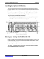
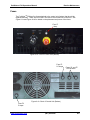
1
ProWriterTM F20 LASER MARKING SYSTEM www.controllaser.com Operations Manual 2419 Lake Orange Drive, Orlando, FL 32837 Telephone 407-926-3500 Fax 407-926-3590 www.controllaser.com Table of Contents Preface.................................................................................................. v Introduction ................................................................................................. v About This Publication ................................................................................ vi Chapter Summary ................................................................................ vi Document Conventions ........................................................................ vii Revisions .............................................................................................. vii Technical Support Directory............................................................... ix Field Service Support.................................................................................. ix Support by Phone................................................................................. ix Support by Fax ..................................................................................... ix Support by E-mail ................................................................................. ix Support by Website .............................................................................. ix Service and Maintenance Programs........................................................... x Advanced Maintenance Training Seminars ................................................ x Product Warranty ........................................................................................ x Parts Repair ............................................................................................... x Replacement and Spare Parts.................................................................... xi Safety .................................................................................................. 1-1 Recommendation........................................................................................ 1-1 Laser Radiation Wavelength....................................................................... 1-2 Recommended Density for Optical Eyewear ....................................... 1-2 Laser Radiation Specifications ............................................................. 1-2 Responsibility of the Laser User ................................................................. 1-2 Performance Requirements ........................................................................ 1-3 1. Protective Housing ........................................................................... 1-3 2. Safety Interlocks ............................................................................... 1-5 3. Remote Interlock Connector............................................................. 1-5 4. Master Key Control........................................................................... 1-5 5. Emission Indicator ............................................................................ 1-5 6. Beam Attenuator............................................................................... 1-6 7. Location of Controls ......................................................................... 1-6 8. Manual Reset ................................................................................... 1-9 9. Labeling ............................................................................................ 1-9 10. Documentation ............................................................................... 1-10 Classification of Laser Functions ................................................................ 1-10 Electrical Safety .......................................................................................... 1-11 Use of Combustible Material....................................................................... 1-12 Safety Label Diagram ................................................................................. 1-13 www.controllaser.com (407) 926-3500 i ProWriterTM F20 Operations Manual Table of Contents System Description ............................................................................ 2-1 Overview ..................................................................................................... 2-1 Specifications .............................................................................................. 2-1 Control Unit ................................................................................................. 2-3 Marking Head ............................................................................................. 2-3 System Design ............................................................................................ 2-5 Marking Field............................................................................................... 2-6 Computer Architecture ................................................................................ 2-6 System Function ................................................................................ 3-1 Laser Basics........................................................................................... .... 3-1 Overview......................................................................................... ..... 3-1 Optional Accessory Control Item.......................................................... 3-1 System Startup Procedure.......................................................................... 3-3 Hardware Status Monitor ............................................................................ 3-4 Automatic Shutdown ................................................................................... 3-4 Restarting the System .......................................................................... 3-4 Manual Shutdown Procedure...................................................................... 3-4 Emergency Shutdown Procedure ............................................................... 3-5 Installation .......................................................................................... 4-1 Receipt and Inspection ............................................................................... 4-1 Unpacking ................................................................................................... 4-1 Space and Environmental Requirements ................................................... 4-2 Electrical Requirements and Connections.................................................. 4-2 Installing Remote Options........................................................................... 4-3 Installing Safety Shutter Interlock......................................................... 4-3 Installing External Devices.......................................................................... 4-4 Installing the Optional I/O Kit ...................................................................... 4-6 Moving and Storing the ProWriterTM F20 .................................................... 4-6 Software Setup .................................................................................... 5-1 Overview ..................................................................................................... 5-1 Run Time .............................................................................................. 5-1 Design View.......................................................................................... 5-2 Command Editor................................................................................... 5-3 System Organization................................................................................... 5-4 Part-Marking Programs ........................................................................ 5-5 Reference Files .................................................................................... 5-5 Secondary Files.................................................................................... 5-6 User Accounts ...................................................................................... 5-6 File Utilization.............................................................................................. 5-6 Help Systems .............................................................................................. 5-6 www.controllaser.com (407) 926-3500 ii ProWriterTM F20 Operations Manual Table of Contents Making Selections....................................................................................... 5-7 Main Menu and Toolbar ....................................................................... 5-7 Hardware Status Monitor...................................................................... 5-7 Hot Keys ............................................................................................... 5-7 Setting the Field Size .................................................................................. 5-7 Viewing and Editing Default Settings.......................................................... 5-7 Creating and Running a Part-Marking Program................................ 6-1 Introduction ................................................................................................. 6-1 Setting Up a Remote Programming Station................................................ 6-1 Setting the Event Order .............................................................................. 6-1 Setting Process Parameters ....................................................................... 6-1 Marking Speed .................................................................................... 6-2 Power ................................................................................................... 6-2 Q-Switch Frequency ............................................................................. 6-3 Galvanometer Settling Time (GST) ...................................................... 6-3 Other Parameters ................................................................................. 6-4 Marking Tips ......................................................................................... 6-4 Types of Marks .............................................................................. 6-4 Material Characteristics ................................................................. 6-4 Other Marking Tips ........................................................................ 6-5 Program Testing and Debugging ................................................................ 6-5 Testing the Marking Image................................................................... 6-5 Testing at a Remote Station .......................................................... 6-6 Testing with the I/O Module Accessory ......................................... 6-6 Testing the Program Code Line-By-Line.............................................. 6-7 Part Positioning........................................................................................... 6-7 Running a Program..................................................................................... 6-7 Marking Requirements ......................................................................... 6-8 Lasing a File ......................................................................................... 6-8 Software Commands ........................................................................... 7-1 Command Quick-Reference Guide............................................................. 7-1 Communications Commands ............................................................... 7-1 Marking Characteristic Commands ...................................................... 7-2 Marking Image Commands .................................................................. 7-2 Mathematical Commands..................................................................... 7-3 Position and Dimension Commands .................................................... 7-4 Program Control Commands................................................................ 7-5 Text/Variable/File Commands .............................................................. 7-6 Routine Maintenance .......................................................................... 8-1 Performing Inspection and Maintenance .................................................... 8-1 Recommended Maintenance Schedule...................................................... 8-1 Testing Power Output ................................................................................. 8-1 Optics Maintenance .................................................................................... 8-3 Inspecting and Cleaning the Scan Mirrors ........................................... 8-3 www.controllaser.com (407) 926-3500 iii ProWriterTM F20 Operations Manual Table of Contents Troubleshooting ................................................................................. 9-1 Overview ..................................................................................................... 9-1 Material Suitability to Laser Marking ................................................ A-1 Part Numbers ...................................................................................... B-1 www.controllaser.com (407) 926-3500 iv Preface Introduction This manual covers safety, system specifications, installation, maintenance, basic troubleshooting procedures, and operations. Diagrams and drawings will be included to assist in the description of components and layout of the ProWriterTM F20 in the Customer Services Manual. WARNING WARNING It is extremely important to read and understand Chapter 1, Safety, before attempting to operate the ProWriterTM F20 Laser Marking System. Control Laser Corporation (CLC) welcomes suggestions for future editions of this manual. Please send your comments to: Attention: Marketing Control Laser Corporation 2419 Lake Orange Drive Orlando, Florida 32837 E-mail: [email protected] Please contact the Field Service department for information regarding the maintenance of the ProWriterTM F20. Phone: 1-866-612-8619, Monday through Friday 8:00 a.m. to 5:00 p.m. EST Fax: 407-926-3551, 24 hours a day, seven days a week E-mail: [email protected] For information about CLC, visit our website at www.controllaser.com. www.controllaser.com (407) 926-3500 v ProWriterTM F20 Operations Manual Preface About This Publication Chapter Summary Technical Support Directory - This directory explains how to contact CLC for technical support by telephone, fax, and e-mail; how to order parts; and how to return components for repair. Information about technical support programs, training classes, and the CLC website are included. Chapter 1. Safety - This chapter describes how the ProWriterTM F20 fulfills the performance requirements established by the United States Title 21, Code of Federal Regulations, Subchapter J (21 CFR), and the European Standard EN 60825:1992. This chapter documents the users responsibility and safety precautions. CAUTION All users should read and understand the safety chapter before attempting to operate the ProWriterTM F20 Chapter 2. System Description - This chapter outlines specifications for the ProWriterTM F20. The following diagrams and descriptions are provided: control unit, marking head, system design (beam-steering), marking field, computer architecture, and system operation (software). Chapter 3. System Function - This chapter provides diagrams and descriptions of the ProWriterTM F20 controls and step-by-step instructions for system startup and shutdown. Chapter 4. Installation - This chapter explains proper procedures for receiving, inspecting, and unpacking the ProWriterTM F20. Space, environmental, and electrical requirements are described. Step-by-step instructions for installing safety interlocks and connecting electrical lines are included. Guidelines for moving and storing the system are also outlined. Chapter 5. Software Setup - This chapter describes the basic features of the Laser Marking StudioTM (LMS). An overview of LMS is provided as well as directions for navigating. Other topics include setting passwords, help system, and accessing other applications. Chapter 6. Creating and Running a Part-Marking Program - This chapter describes the main concepts involved in using the LMS software to create and run a part-marking program. It also describes how to set up a remote programming station and how to select the LMS editor that best meets your programming needs. Setting process parameter values (speed, power, and Q-switch frequency) are explained to achieve optimum marking quality. This chapter also describes testing and debugging programs and provides step-by-step instructions for loading and running programs. Chapter 7. Software Commands - This chapter provides a Quick – Reference Guide to all of the software programming commands. For details on creating, editing, and lasing programs in the Visual and Command Editors, please refer to the online manual. www.controllaser.com (407) 926-3500 vi ProWriterTM F20 Operations Manual Preface Chapter 8. Routine Maintenance - This chapter contains step-by-step instructions for maintaining the ProWriterTM F20 including inspecting and cleaning the galvanometer mirrors and focusing lens assembly. Chapter 9. Troubleshooting - This chapter provides general instructions for troubleshooting the ProWriterTM F20 according to the laser status indicators. Appendix A. Material Suitability to Laser Marking - This appendix lists the marking quality that can be achieved with the most common types of marking materials. Appendix B. Replacement Part Numbers - This appendix contains the current part numbers for ordering additional parts. Document Conventions Special graphics, described below, are used in this manual to emphasize certain types of information. When paired with a CAUTION notice, this emphasizes information about actions that might result in equipment damage. When paired with a WARNING notice, this emphasizes information that might result in personal injury. Revisions If any changes occur after the printing of this manual, a Revision Page will be included in the back of this manual. www.controllaser.com (407) 926-3500 vii Technical Support Directory Field Service Support A qualified maintenance technician should troubleshoot the laser system before contacting the Field Service department. Attempting to isolate the source of the problem will make it easier for the field service technician to assist you. Have the model name and serial number of the laser available when you contact Field Service. This information is located on the Data Sheet in the Customer Service Manual. Support by Phone The Field Service department can be contacted at (1-866) 612-8619, Monday through Friday, 8:00 a.m. to 5:00 p.m. Eastern Time. After 5:00 p.m., an answering service will take your message and notify a field service technician of your requirements by the next business day. Support by Fax The Field Service department can be contacted by fax at (407) 926-3551 24 hours a day, including weekends. Faxes received after business hours and on weekends will be responded to the next business day. Support by E-mail The Field Service department can be contacted by e-mail at [email protected]. Support by Website Visit our website at www.controllaser.com to learn more about Control Laser Corporation (CLC), our laser markers and engravers, and various applications. www.controllaser.com (407) 926-3500 ix ProWriterTM F20 Operations Manual Technical Support Directory Service and Maintenance Programs The Field Service department offers several service and maintenance programs that provide expert on-site support from factory representatives. Programs may be purchased on a quarterly or annual basis. Contact Field Service for details at (1-866) 612-8619 or [email protected]. Advanced Maintenance Training Seminars Advanced maintenance training seminars are held once a month at CLC. Contact Field Service for enrollment information at (1-866) 612-8619 or [email protected]. Product Warranty The Customer Service Manual explains the warranty covering the ProWriterTM F20. Parts Repair If a laser component fails, contact Field Service immediately. Most repairs can be accomplished within 24-48 hours upon receipt of the component. Some power supply units may take additional time to replace/repair because they may require outside vendor participation. Before returning any parts to CLC for repair/replacement contact Customer Service at (1866) 612-8619. You will be supplied with a Return Material Authorization (RMA) number used to track the part during repair and shipping. Return all components to CLC by United Parcel Service (UPS), Federal Express, or any local carrier that can track your package to: Attention: RMA number Control Laser Corporation 2419 Lake Orange Drive Orlando, Florida 32837 www.controllaser.com (407) 926-3500 x ProWriterTM F20 Operations Manual Technical Support Directory Replacement and Spare Parts In North America, replacement and spare parts must be ordered directly through CLC. Parts can be shipped overnight at the customer’s request. Spare part kits and test equipment kits are also available. See Appendix B, Part Numbers, for current part numbers of available ProWriterTM F20 parts and test equipment. To order parts or a current parts catalog, contact Customer Service at Control Laser: Attention: Customer Service Control Laser Corporation 2419 Lake Orange Drive Orlando, Florida 32837 Telephone: Fax: (1-866) 612-8619 (407) 926-3551 In Europe, replacement and spare parts may be ordered through Excel Technology GmbH at: Roenstgenstr., 84 D-6100 Darmstadt Germany Telephone: 49-6151/9380-0 Telex: 49-6151/9380-25 See Appendix B, Part Numbers, for current part numbers. www.controllaser.com (407) 926-3500 xi Safety CAUTION CAUTION Use of controls, adjustments, or performance of procedures other than those specified herein may result in exposure to hazardous radiation. Recommendation Control Laser Corporation (CLC) recommends the Safety chapter be read thoroughly by all personnel before operating or performing maintenance on the ProWriterTM F20. Commitment Statement The contents in this manual are not specific to the specific ProWriterTM F20 you purchased. See the Customer Service Manual for a complete listing of diagrams, drawings, labels, and parts. Compliance Statement The ProWriterTM F20 is certified by Control Laser Corporation as a Class IV product in accordance with Title 21, Code of Federal Regulations, Subchapter J, (21 CFR), and European Standard EN 60825:1992. Check your customer service manual for specific classification of your laser. Compliance may be verified by contacting: Office of Compliance (HFZ-312) Center for Devices and Radiological Health US Department of Health & Human Services 2098 Gaither Road Rockville, MD 20850 Telephone: (301) 594-4654 www.controllaser.com (407) 926-3500 1-1 ProWriterTM F20 Operations Manual Safety Laser Radiation Wavelength The ProWriterTM F20 emits infrared laser (IR) radiation at 1,062 nanometers (nm) and visible laser radiation (laser pointer) at 660 nanometers. The IR laser poses the greatest risk of injury if the safety precautions in this manual are not followed. The 660 nm radiation used as a locating beam (the laser diode) poses a less significant risk but still requires adherence to the safety precautions. The specifications in the following chart are provided to assist the Laser Safety Officer (see Responsibility of the Laser User below) in evaluating the hazard potential of the laser. These specifications represent the “worst-case” potential for short-term, peak laser emission and should not be confused with the operational specifications given in Chapter 2, System Description. Recommended Optical Density for Eyewear: ProWriterTM F20 (IR) ProWriterTM F20 (laser pointer) 6 4 Laser Radiation Specifications Specification IR Laser Pointer Wavelength: 1,062 nm (typ) 660 nm Peak Power @ 20 kHz: 10 kW n/a Pulsewidth: 100 ns (typ) n/a CW Power: 20 W 0.5 mW Divergence: Beam Size: < 0.3mrad 7.5 mm (typ) < 0.3 mrad 1 mm Responsibility of the Laser User The performance requirements described in paragraphs 1-9 are defined by the United States government and the European Union as the responsibility of the laser manufacturer. The responsibility of the user is the safe use of the laser defined in ANSI Z136.1; the American National Standard for the Safe Use of Lasers; and Section Three of EN 60825 - Radiation safety of laser products, equipment classification, requirements, and user’s guide. These standards require the user to appoint a Laser Safety Officer to oversee the use of this equipment. This individual shall have the authority and responsibility to evaluate, monitor, and enforce the control of laser hazards. See the appropriate standard: ANSI Z136.1 in the United States of America and Section Three of EN 60825 in the European Union for the specific responsibilities of the Laser Safety Officer. www.controllaser.com (407) 926-3500 1-2 ProWriterTM F20 Operations Manual Safety ANSI Z136.1 is issued by the American National Standards Institute (ANSI) as a recommended safety guide for the use of laser products in the United States of America. ANSI cannot enforce adherence to the guide. However, OSHA, the Occupational Safety and Health Administration, uses the guide as its inspection standard when it inspects workplaces that use lasers. Therefore, the guide carries the authority of the United States government. It is recommended the procedures outlined in the guide be followed when operating the ProWriterTM F20 and the user contact local and state authorities to determine if any additional regulations may apply. ANSI Z136.1-2000 may be ordered from: Laser Institute of America (LIA) 13501 Ingenuity Drive Suite 128 Orlando, FL 32826-3009 Telephone: 407-380-1553 Fax: 407-380-5588 www.ANSI.org EN 60825 is issued by the European Committee for Electrotechnical Standardization (CENELEC) as a safety standard for the manufacture and use of laser products in the European Union. It is enforced individually by the government of each member country of the European Union. For more information, please use the address, phone number, and/or web site below. CENELEC 35, Rue de Stassartstraat B-1050 Brussels, Belgium Tel: +32 2 519 68 71 Fax: +32 2 519 69 19 www.cenelec.org Performance Requirements 21 CFR and EN 60825 specify certain performance requirements (features) that must be incorporated into or provided with each laser product for radiation safety purposes. These features with an explanation of their function in the ProWriterTM F20 are described in sections 1-10 in this chapter. 1. Protective Housing The laser radiation emitted by a Class IV laser product must be contained within a protective housing at all points where access to radiation is not required during normal operation of the product in the performance of the function for which it was designed. [21 CFR 1040(f)(1) and EN 60825, 4.2]. Laser radiation generated by the ProWriterTM F20 originates in the controller and is delivered via an optical fiber to the marking head assembly shown in Figures 1-1 and 1-2. The marking head assembly manipulates and focuses the laser beam at the workpiece. Laser radiation is www.controllaser.com (407) 926-3500 1-3 ProWriterTM F20 Operations Manual Safety completely contained within the enclosed marking head assembly except where it exits to impact the workpiece. In the standard marking head assembly configuration (Figure 1-1, Figure 1-2), laser radiation is emitted downward when mounted vertically. The user can also mount the marking head assembly horizontally. Emissions Indicator FRONT END VIEW Lens Standard Beam Path Figure 1-1. End View of Standard Marking Head Assembly Configuration Emissions Indicator Cables SIDE VIEW Lens Standard Beam Path Figure 1-2. Side View of Standard Marking Head Assembly Configuration WARNING The ProWriterTM F20 marking head assembly contains no components requiring access during normal operation. The laser should never be operated without its cover except during authorized service functions requiring access. The ProWriterTM F20 is certified as a Class IV product or otherwise stated in your CUSTOMER SERVICE MANUAL. Access to laser radiation is possible during operation and all personnel in the operating area must wear laser eyewear with an optical density (OD) as recommended on page 1-2. www.controllaser.com (407) 926-3500 1-4 ProWriterTM F20 Operations Manual Safety 2. Safety Interlocks 2. Safety Interlocks Any part of the protective housing that must be opened, removed or displaced during normal operation of the laser must be interlocked to prevent access to laser radiation. [21 CFR 1040.10(f)(2) and EN 60825,4.3]. No interlocks are required. It is not necessary to open or remove any part of the laser marking head assembly during normal operation. 3. Remote Interlock Connector 3. Remote Interlock Connector A Class IV laser must have a means to shut down the laser from a remote interlock. [21 CFR 1040.10(f)(3) and EN 60825, 4.4]. The remote interlock connector on the ProWriterTM F20 allows connection of external interlock circuits or switches for the control unit which can shutdown the laser. See Chapter 4, Installation for installation instructions. 4. Master 4. Master Key Control Each Class IV laser must be provided with a keyswitch which will prevent operation of the laser when the key is removed. The key must be removable only in the OFF position, and must disable the laser when removed. [21 CFR 1040.10(f)(4) and EN 60825, 4.5]. The master key control for the ProWriterTM F20 is located on the main control panel (see Figure 1-3.) WARNING The master key to operate the ProWriterTM F20 should be given only to personnel authorized by the Laser Safety Officer. The laser should never be left unattended while running or while the key is in the laser. 5. Emission Indicator An emission indicator is required to provide visible signal during emission of laser radiation, and sufficiently prior to emission to allow a person to avoid exposure to laser radiation. [21 CFR 1040.10(f)(5) and EN 60825, 4.6]. There are two emission indicators on the ProWriterTM F20, one on the main control panel and a second on the laser marking head assembly. Both indicators light when the keyswitch is turned to the CONTROL ON position indicating the laser is being activated. The indicators remain on until the keyswitch is turned to the POWER OFF position. The keyswitch must be turned to the POWER ON position to activate the power supply that activates after a few seconds delay. www.controllaser.com (407) 926-3500 1-5 ProWriterTM F20 Operations Manual Safety Figure 1-2 shows the emission indicator on the laser marking head assembly. The emission indicator on the control panel is the POWER ON indicator (see Figure 1-3.) 6. Beam Attenuator A beam attenuator (safety shutter) must be provided to enable the user to terminate lasing without turning off the master keyswitch or main power switch. [21 CFR 1040.10(f)(6) and EN 60825, 4.7]. The shutter terminates lasing by blocking the laser beam before it reaches the output optics. The ProWriterTM F20’s safety shutter is located inside the sealed marking head assembly. The shutter is actuated when the shutter switch located on the control panel is moved to the “closed” position. The external interlocks connected to the remote interlock connector can also actuate the shutter. 7. Location of Controls 7. Location of Controls Controls which are necessary for operation of the laser must be located so they can operate without exposure to laser radiation. [21 CFR 1040.10 (f)(7) and EN 60825, 4.8]. All controls used to operate the ProWriterTM F20 are located in the control unit (see Figures 1-3a and b.) The marking head assembly connects to the control unit by an umbilical cord allowing placement of the marking head assembly anywhere within the radius of the cord. CAUTION The ProWriterTM F20 is a Class IV product or otherwise stated in your Customer Service Manual and should be operated in accordance with procedures in this manual, ANSI Z136.1, EN 60825:1992, and local procedures issued by the Laser Safety Officer. www.controllaser.com (407) 926-3500 1-6 ProWriterTM F20 Operations Manual Safety Computer Display USB Ports Keyboard, Mouse, and pad (not shown) Floppy Disk Drive See Figure 1-3b DVD/CD-RW Figure 1-3a. ProWriterTM F20 Control Unit Keyswitch Laser On Indicator Fuse Emergency Stop Switch Shutter/pointer Switch Circuit Breaker Figure 1-3b. ProWriterTM F20 Control Unit (bottom half) www.controllaser.com (407) 926-3500 1-7 ProWriterTM F20 Operations Manual Safety Refer to Figures 1-3a and b for the location of the following controls: 1. Emergency Stop Switch Press the Emergency Stop switch in to shut down the laser system. The Emergency Stop switch turns off power to the laser. The control system remains on. Turn the switch to the right to release the Emergency Stop switch (following the directional arrows). 2. Keyswitch The keyswitch has three positions: • Power Off - Turns off all systems. The key can be removed only in this position. • Control On - Activates the laser’s computer system and loads the ProWriterTM F20 software which can be operated in this mode. • Power On - Activates the laser’s power supply and internal cooling system. CAUTION Do not turn the keyswitch to the “Power On” position while a program is loading. This may cause the laser to start at higher than normal levels. This “hard” start may cause serious damage to the computer, drivers, and other key components. CAUTION When the keyswitch is in the Power On position, current is present and the system is capable of lasing. 3. Power On Indicator Light illuminates to indicate that the system is capable of laser emission. 4. Mouse and Mouse Pad 5. Floppy Disk Drive A 3.5 inch 1.4-megabyte floppy disk drive for program and data storage 6. DVD-RW Drive 7. USB Ports 8. Computer Keyboard A standard keyboard is provided for laser software control and data entry. www.controllaser.com (407) 926-3500 1-8 ProWriterTM F20 Operations Manual Safety 9. Computer Display A flat-screen LCD allows visual interaction with the laser’s operating software. 10. Shutter/Pointer Switch The shutter/pointer switch has three positions: • Pointer – Activates the ViDAL (Visible Diode Alignment Laser) system. Users may select DRYRUN MODE or ALIGN RUN MODE. Either may be operated with the interlock disabled. • Shutter Open – Opens shutter to allow the laser beam to pass through the galvo head. • Shutter Closed – Closes the shutter to block the laser beam from passing through the galvo head. 8. Manual Reset A class IV or otherwise stated laser in your Customer Service Manual must contain a mechanism requiring a manual reset to resume lasing following interruption through the remote interlock connector or from the loss of main electrical power. [21 CFR 1040.10 (f)(10)]. To restart the ProWriterTM F20 and resume lasing following shutdown through the remote interlock connector or the loss of main power: 1. Turn the keyswitch to the Power Off position. 2. Turn the keyswitch to the Control On position. The computer and control circuits restart. 3. Turn the keyswitch to the Power On position. The power supply restarts and restarts the laser. CAUTION Do not turn the keyswitch to the “Power On” position while a program is loading. This may cause the laser to start at higher than normal levels. This “hard” start may cause serious damage to the computer, drivers, and other key components. 9. Labeling 9. Labeling Labels must be affixed to each laser to identify the manufacturer, certify compliance with 21 CFR and EN 60825, provide warnings to the user about the wavelength, level, and location of accessible laser radiation present, and give precautions that should be taken to avoid exposure to the laser radiation. [21 CFR 1040.10(g) and EN 60825, 5]. Figure 1-4 at the end of the chapter illustrates the labels affixed to the ProWriterTM F20 in compliance with this requirement. For a complete and accurate showing of labels check your Customer Service Manual. www.controllaser.com (407) 926-3500 1-9 ProWriterTM F20 Operations Manual Safety 10. Documentation 10. Documentation Instructions must be provided that will enable the user to safely operate and maintain the laser. [21 CFR 1040.10(h) and EN 60825, 6.1]. It is recommended the Operations and Customer Service manuals be thoroughly studied by all personnel who have any responsibility for the laser prior to the laser’s operation. The Operations manual gives instructions for proper operation and maintenance of the ProWriterTM F20. The manual also provides warnings and cautions that must be observed by the user to prevent unnecessary exposure to laser radiation. Classification of Laser Functions Laser products are classified according to the maximum level of laser radiation within human access during operation only. Levels accessible only during maintenance or service do not affect the classification. Therefore, it is possible for class I or class II products to contain class IV lasers. It is the responsibility of the manufacturer to determine whether specific functions are operation, maintenance, or service. The following definitions apply: • Operation - Consists of functions by which the product accomplishes its intended purpose. These may include loading workpieces or documents and setting and manipulating external controls. • Maintenance - Consists of functions performed by the user to assure performance. These may include cleaning and replacement of expendables. • Service - Usually means repair. Service may be performed by specially trained service personnel or by sophisticated users following instructions specifically indicated as service instructions. Certain maintenance procedures will be considered service if they are infrequent, complex, or highly specialized. The following chart lists the functions of operation, maintenance, and service associated with the ProWriterTM F20 described in this manual. WARNING All personnel in the vicinity of the laser while it is in operation must follow all prescribed safety procedures and use appropriate safety equipment. This includes wearing laser eyewear with an optical density (OD) as recommended on page 1-2. Failure to follow these instructions may result in the exposure of personnel to hazardous laser radiation. www.controllaser.com (407) 926-3500 1-10 ProWriterTM F20 Operations Manual Safety Classification of Laser Functions Function Classification Requires Lasing Operation of Laser Controls Operation Yes Cleaning Optics Maintenance No Replacements of Electrical Assemblies & Components Service No Replacement of Mechanical Components Service No Replacement of Optical Components Service No Troubleshooting & Repair Service See Note Testing Following Repair Service See Note Optical Alignment/Adjustment Service Yes Programming Service No Connections to Remote Interlock Connector Service No Service No Service Yes Setup/Fixture Alignment Test Marking (following repair, programming, setup) Note: Some troubleshooting and testing functions will not require the laser to be lasing. Electrical Safety • Disconnect main power line(s) before working on any electrical equipment if it is not necessary for the equipment to be operating. • After disconnecting power, wait at least five minutes for the capacitors to discharge through the bleeder resistors before touching any electrical equipment. • Do not short or ground the power supply output. The power supply is not electrically isolated from the power line. Protection against possible hazards require proper connection of the ground terminal on the power cable and an adequate external ground. Check these connections at the time of installation and periodically thereafter. www.controllaser.com (407) 926-3500 1-11 ProWriterTM F20 Operations Manual Safety • Never work on electrical equipment unless there is another person nearby who is knowledgeable of the operation and hazards of the equipment and who is competent to administer first aid. • When possible, keep one hand away from the equipment to reduce the danger of current flowing through the body. • Special measurement techniques are required for this system. Ground references must be selected by a technician who has a complete understanding of the system operation and associated electronics. Use of Combustible Material WARNING A fire or explosion could occur if the laser beam is allowed to contact flammable or combustible materials. Care must be taken to ensure that such materials are kept away from any part of the laser beam path. (See Figures 1-1 and 1-2) www.controllaser.com (407) 926-3500 1-12 ProWriterTM F20 Operations Manual Safety 3 • Never work on electrical equipment unless there is anoth 4 4 Both sides 3 3 3 4 3 1 3 Both sides 2 2 Both sides 1 1 2 Label 1 and 2 are on both sides of the laser 1 head..Label 3 is located on top of laser head and on inside frame. Lable 4 2 on side of laser is located cabinet 1 2 1 4 3 INVISIBLE & VISIBLE RADIATION AVOID EYE OR SKIN EXPOSURE TO DIRECT OR SCATTERED RADIATION. CLASS IV LASER PRODUCT MAX OUTPUT 1kW, 20kZ @ 1060 nm and 1mW @ 660nm 2419 LAKE ORANGE DRIVE ORLANDO FL 32837 CAUTION VISIBLE AND/OR INVISIBLE LASER RADIATION WHEN OPEN. AVOID EYE OR SKIN EXPOSURE TO DIRECT OR SCATTERED RADIATION. Control Laser Corporation 2419 Lake Orange Drive, Orlando, Florida, USA Model No. 12345 Input Power: 230V, 30A, 50/60 Hz Located at upper-right-rear of Control Cabinet. www.controllaser.com MODEL SERIAL DATE MFD Assembled in USA THIS PRODUCT COMPLIES WITH 21 CFR, SUBCHAPTER J., AND EN 60 825 : 1992, AS APPLICABLE. Figure 1-4. ProWriterTM F20 Labels Check Customer Service manual for additional labels. Baublys Control Laser Corp. 2419 Lake Orange Dr Orlando, FL 32837 Input Power: 120 V, 7A 50/60 Hz (407) 926-3500 1-13 System Description Overview The ProWriterTM F20 is a general-purpose industrial marking system. It is designed to permanently mark a variety of materials including hardened metals, ceramics, carbides, silicon, and plastics. It is capable of marking alphanumeric characters, barcodes, 2D matrices, and graphics. The system is computer-controlled and is easily adaptable to manual, semi-automatic, or fully automatic part handlers. The ProWriterTM F20 consists of a control unit connected to the laser marking head assembly by an umbilical cord and fiber cable. The control unit contains power supplies, computer, fiber laser source, and power distribution boards. For a general description of how industrial lasers work, see Laser Basics in Chapter 3, System Function. Specifications Performance Marking field: Working Distance (Effective Focal Length) Depth of Field (Range of In-Focus) 4.0 in. Square (100 mm): 6.42 in. (163 mm) .020 in. (1.02 mm) 6.0 in. Square (150 mm): 7.52 in. (191 mm) .040 in. (1.02 mm) 12.0 in. Square (300 mm): 13.78 in. (350 mm) .060 in. (1.54 mm) Positioning Speed: 275 in/s (7000 mm/s) Repeatability: 4.0 in. Square (100 mm): +/- .000003 in. 6.0 in. Square (150 mm): +/- .000005 in. 12.0 in. Square (300 mm): +/- .000010 in. Writing Modes: www.controllaser.com Linear, Ring, and Angular (407) 926-3500 2-1 ProWriterTM F20 Operations Manual System Description Character Fonts: True Type fonts from Windows and special Laser Marking StudioTM (LMS) software fonts. Graphics: User-programmable Imports raster and vector graphics For a complete listing refer to the LMS help tab. Laser Controller Computer: Marking controller: IBM-compatible Pentium Type Program Storage: 3.5 inch 1.4 MB floppy disk drive DVD/CD-RW drive, hard drive, USB ports Video Display: Flat-screen LCD, 1024 x 768 resolution Diagnostics: Self-diagnosis, operator-viewable Wavelengths Infrared (IR): 1,062 nm nominal Laser Diode Wavelength: Visible red light at 660 nm Mechanical Control Unit: 23.0 inch L x 17.5 inch W x 12.0 inch H (584 mm L x 445 mm W x 305 mm H) ~97 lbs. (44 kg.) Scanner: 8.5 inch L x 7.0 inch W x 7.0 inch H (216 mm L x 178 mm W x 178 mm H) ~10 lbs. (4.5 kg.) Umbilical Length: 4.9 ft. (1.5 m) standard; 16 ft. (4.9 m) optional Environmental Operating Temperature: 33°F to 93°F (1°C to 33°C) Storage Temperature: 14°F to 140°F (-10°C to 60°C) Relative Humidity: 10% to 95% (non-condensing) Atmospheric Pressure: 0 to 6,000 ft (760 to 604 mmHg) Storage Life: 5 years www.controllaser.com (407) 926-3500 2-2 ProWriterTM F20 Operations Manual System Description Cooling Requirements Type of Cooling: Forced air over heat sink Utilities Line Voltage: 115 VAC (+6%, -10% VAC) standard (50/60 Hz) 230 VAC (+6%, -10% VAC) standard (50/60 Hz) (optional) Current Consumption: 7 A (typical); 9 A (max.) Normal Average Output: 20 watts Control Unit The ProWriterTM F20 control unit contains computers, drives, controls, and indicators as shown in Figures 1-3a and b in Chapter 1, Safety. Power and laser umbilical connections are located at the rear of the control unit. Marking Head The ProWriterTM F20 laser standard marking head configuration is shown in Figure 2-3. The laser beam emits downward. www.controllaser.com (407) 926-3500 2-3 ProWriterTM F20 Operations Manual System Description Emissions Indicator FRONT END VIEW Lens Standard Beam Path Figure 2-2. End View of Standard Marking Head Assembly Emissions Indicator Cables SIDE VIEW Lens Standard Beam Path Figure 2-3. Side View of Standard Marking Head Assembly www.controllaser.com (407) 926-3500 2-4 ProWriterTM F20 Operations Manual System Description System Design X-Axis Galvanometer Laser Upcollimator Y-Axis Galvanometer Upcollimator shown Laser not not shown forfor clarity. clarity Flat-Field Focus Lens Y X Figure 2-4. Post-focus Beam-steering Design The galvanometer head contains two scan mirrors, each mounted on a high-speed, highaccuracy galvanometer. The galvanometers are mounted to provide independent beam motion on both the x and y axis of the marking field. The laser beam first reflects off the xaxis scan mirror then off the y-axis scan mirror. Computer signals move the mirrors steering the laser beam as it moves across the marking surface. The flat-field lens assembly is the last optic the beam passes through before reaching the marking surface. The lens assembly focuses the beam reducing its diameter and increasing its energy density. The lens diameter has an equal corresponding marking field diameter. The ProWriterTM F20 can be installed for manual, semi-automatic, and fully automated operation. www.controllaser.com (407) 926-3500 2-5 ProWriterTM F20 Operations Manual System Description Marking Field The ProWriterTM F20 has three fixed marking field sizes available in 4 inch, 6 inch, and 12 inch square fields (see Figure 2-5). Marking Head over the Marking field Y-axis X-axis Figure 2-5. 6 inch Marking Field with a Marking Head Assembly The marking field is defined as a Cartesian coordinate system. The coordinate system origin is in the center of the marking field. The X-axis of the coordinate system is parallel with the long dimension of the laser marking head. The Y-axis is perpendicular to the long dimension of the marking head. Computer Architecture The ProWriterTM F20 incorporates a Pentium class computer for the operator interface and program execution. All part program access, creation, editing, and operator input is performed on the system computer. The system computer also executes part programs and controls the marking process. www.controllaser.com (407) 926-3500 2-6 System Function Laser Basics Overview Laser is an acronym for Light Amplification by Stimulated Emission of Radiation. Simply stated, the laser is a light amplifier. Lasers amplify light by absorbing and emitting energy. Absorption can be either electronic on the atomic level or rotational/vibrational on the molecular level. The emitted energy is a highintensity beam of laser light. Lasers emit optical radiation which can be either invisible (infrared) or visible (laser pointer diode) light. Optical radiation is referred to as non-ionizing to distinguish it from ionizing radiation which is the type of radiation associated with X-rays and gamma rays. While overexposure to ionizing radiation such as frequent medical X-rays may cause health problems, the non-ionizing radiation emitted by lasers do not pose similar health risks even with frequent and long-term non-direct exposure. Direct exposure to optical radiation can, however, pose serious health hazards to the skin and eyes. Lethal electrical hazards may also be present in all lasers. A laser-induced reaction on certain types of marking materials can release hazardous particles and gaseous products. Review Chapter 1, Safety, for instructions on how to avoid eye and skin injuries and electrical hazards. Never operate or service the ProWriterTM F20 without following the safety procedures specified in the safety chapter of this manual. Optional Accessory Control Item (I/O Module) User-Programmable eight Input and eight Output Modules The user-programmable input/output lines are available as an optional accessory module purchased separately for the ProWriterTM F20. Many of the more sophisticated ProWriterTM F20 programming commands require this accessory. (See Figure 3-3) www.controllaser.com (407) 926-3500 3-1 ProWriterTM F20 Operations Manual System Function Figure 3-3. Optional I/O Module The I/O lines act as interfaces between the laser computer system and any peripheral devices. There are 16 user-programmable I/O lines per module. Eight lines are for input and eight for output. A maximum of two I/O modules per ProWriterTM F20 are allowed for a maximum total of 32 user-programmable I/O lines. Peripheral devices are connected to the I/O lines through Opto-22 modules. The accessory I/O modules should be installed on a workstation separate from the ProWriterTM F20 control unit. Each I/O line has a corresponding bit. A bit can be in one of two states: off (binary code 0) or on (binary code 1). When a bit is on, its LED on the I/O rack turns on; when a bit is off, the LED turns off. The Opto-22 module defines the type of signal (AC or DC) and voltage range used to change the state of the bit. On the first optional I/O module, the 16 corresponding I/O bits are numbered 0 to 15 and are read from left-to-right. In the ProWriterTM F20 programming language, the I/O lines are always identified using this numbering system. The first eight I/O bits (0-7) are input signals to the ProWriterTM F20 from outside devices and the last eight bits (8-15) are output signals from the ProWriterTM F20 to outside devices. Bit zero (K0 on the I/O board) is dedicated for “start write” input. Each time a “start write” signal is sent the laser marks the currently loaded program. Bit eight (K8) is dedicated for “write complete” input. Each time the laser finishes marking a program the K8 bit tells the external equipment the laser is finished marking. Bits zero and eight cannot be used for any purpose other than start write and write complete, respectively. On the second optional I/O module, the 16 corresponding bits are numbered 16 to 31 and are read from left-to-right. The first eight I/O bits (16-23) are input signals to the ProWriterTM F20 from outside devices and the last eight bits (24-31) are output signals from the ProWriterTM F20 to outside devices. The following commands interface with the user-programmable I/O lines: www.controllaser.com (407) 926-3500 3-2 ProWriterTM F20 Operations Manual System Function • TSTBIT - Forces the laser system to check the state of a user-programmable bit (input only) • CLRBIT - Forces the laser system to clear (turn on) a user-programmable bit (input only) • SETBIT - Forces the laser system to set (turn off) a user-programmable bit (output only) For additional information on how to control the I/O lines through program commands, see the SETBIT, CLRBIT, and TSTBIT commands in the on-line manual. System Startup Procedure To start the ProWriterTM F20: 1. On the control panel, turn the safety shutter switch to the Close position. 2. Make sure the Emergency Stop switch is in the pulled-out position. 3. Insert the key into the keyswitch and turn to the Control On position. WindowsTM XP and the software application, Laser Marking StudioTM (LMS), opens automatically and the status window displays. Note: Programs can be written at this point, with the system in the Control On state. 4. When ready to start marking, turn the keyswitch to the Power On position. Hardware Status Monitor The Hardware Status Monitor reports the status of hardware components to the operator. If the software application is unable to read any hardware sensors the corresponding indicator will show Unknown. See Figure 3-4 below. www.controllaser.com (407) 926-3500 3-3 ProWriterTM F20 Operations Manual System Function Figure 3-4. Hardware Status Monitor Automatic Shutdown When certain functions vital to laser operation fail, the laser system’s safety interlocks are triggered. The power to the laser is turned off but the computer controls remain on. The System Defaults Status dialog box will display and detail the fault or faults. When automatic shutdown occurs, see the Hardware Status Monitor and immediately contact a qualified maintenance technician. Restarting the System When automatic shutdown occurs, see the system log file Log.dat for a record of the events leading to shutdown. A qualified maintenance person should troubleshoot the cause of the shutdown. (See Chapter 9, Troubleshooting, for troubleshooting guidelines.) After the problem has been corrected, follow the instructions in System Startup Procedure in this chapter. Manual Shutdown Procedure To shut down the ProWriterTM F20 system manually, close the software and then exit Windows. To exit LMS: 1. Press <Alt> + <F4> or click on File > Exit. 2. Turn the safety shutter switch to the Close position. To exit Windows: 1. Click on www.controllaser.com at the bottom of the screen. The Start menu displays. (407) 926-3500 3-4 ProWriterTM F20 Operations Manual System Function 2. Select Shut Down. The Shut Down Windows dialog box displays. 3. Click on Shut down the computer. 4. At the confirmation prompt, click on Yes. Turn the keyswitch to the Power Off position when the computer shuts down automatically. 5. Remove the key from the keyswitch. Emergency Shutdown Procedure Press the red Emergency Stop switch on the front control panel. The power to the laser is turned off but the computer controls remain on. To release the Emergency Stop switch, turn the switch to the right (following the directional arrows) and pull the switch up. www.controllaser.com (407) 926-3500 3-5 Installation Receipt and Inspection The ProWriterTM F20 is thoroughly inspected and carefully packed before leaving Control Laser’s Corporation (CLC) factory. The carrier assumes responsibility for the unit’s safe delivery. Any claims for loss or damage sustained in transit must be made against the carrier. Carefully inspect the shipment upon receipt prior to signing for the delivery. • Ensure the container is in an upright position as marked by the container labels. • Check the shock and tilt indicators on the system. If one or more indicators are red inspect the system for damage. Contact the carrier immediately. Any damage, loss, or discrepancies discovered during unpacking should be reported to the carrier immediately. Not immediately reporting damage or discrepancies of the shipment could result in the carrier refusing to honor a claim. All claims should be confirmed in writing as required by the carrier. For claim purposes, it is recommended all packing material be retained. CAUTION WARNING Do not turn on the laser until the Safety and Installation chapters in this manual have been thoroughly read and understood and all installation requirements have been met. Unpacking 1. Ensure the shipping containers are in the upright position as labeled. 2. Cut and remove any bands or straps from the container. 3. Carefully remove any packing material from the equipment. 4. Check the packing list against the equipment received. Report any discrepancies to both the carrier and CLC Field Service department (407-926-3550). 5. Ensure all packing lists, manuals, drawings, and accessory packages are removed from the packing material before it is stored. It is recommended to retain all packing materials. In the unlikely event the laser must be returned, pack the laser or parts in a suitable container for shipping. CLC is not responsible for any damage on returned laser or parts. www.controllaser.com (407) 926-3500 4-1 ProWriterTM F20 Operations Manual Installation The temperature where the laser is installed should not be less than 33°F (1°C) or greater than 93°F (33°C), non-condensing humidity. Space and Environmental Requirements The ProWriterTM F20 should be installed in an area as free as possible from the following: • Contaminants such as dust and oil mist • Combustible and flammable materials such as explosive fumes and gases • Corrosives such as acid vapors • The system should not be subjected to high energy level radio frequency emissions such as a two-way radio or broadcasting equipment. CAUTION The infrared laser emissions might interfere with the infrared sensors of nearby equipment. The floor or foundation where the laser is installed must be level and firm. It must not be subjected to vibration or shock. The temperature where the laser is installed should not be less than 33°F (1°C) or greater than 93°F (33°C), non-condensing humidity. IMPORTANT: • Do not turn on the laser if there is any condensation on the output casing of either the laser head or the control unit. Remove the condensation with clean warm air. • Never place the unit in a location where excessive heat, moisture, or corrosive materials are present. • If the system is moved into the working location from a cold environment, leave the system for a few hours to warm up before installing it. Electrical Requirements and Connections All ProWriterTM F20’s use a standard 115 VAC (+6%, -10%), 50/60 Hz electrical plug connection or an optional 230 VAC (+6%, -10%), (50/60 Hz). Also refer to the electrical data tag on the system control unit cabinet to verify the input power requirements. www.controllaser.com (407) 926-3500 4-2 ProWriterTM F20 Operations Manual Installation Installing Remote Options The remote interlock connector on the ProWriterTM F20 allows connection of external interlock circuits or switches. Installing Safety Shutter Interlock Note: The following procedure is only used when the laser is integrated into a Class I/II certified workstation. Connections are provided to attach external interlock switches to the safety circuit controlling the shutter. This feature allows the laser to be integrated into an enclosed workstation with the door(s) to the workstation protected by interlock switches wired into the safety circuit. When properly configured, the interlocks cause the laser to stop operation when the workstation door(s) is open. If the workstation has multiple doors, each door must have a separate interlock switch and all must be wired in series. Interlock switches used on access doors of workstations must be of the type so the switch contacts electrically open to break the interlock circuit. Dual switches wired in a series may be used on each door to provide redundancy in the event of failure of one of the switches. Means of defeating or overriding safety interlocks are not recommended. To install interlock switches: 1. Shut off the main electrical disconnect supplying power to the laser and appropriately tag and lock it out. 2. Use 22-24 AWG two-conductor jacketed cables appropriate to the environment. Run the cables from the external interlock switch to connector INT. Mount a normally open switch rated for 24 VDC @ 1-amp on the workstation. Connect the wires to the interlock switches. If multiple doors require interlock protection use a separate switch for each door and wire in series. Wires are jumpered for class IV operation. INT Figure 4-1. Laser Controller www.controllaser.com (407) 926-3500 4-3 ProWriterTM F20 Operations Manual Installation Installing External Devices Basic I/O Start Write An external signal from either a PLC or external power source, via a normally open switch, can be connected to the laser to begin marking of the currently loaded program each time a voltage is provided to the “start write” input. Activating this switch in a continuous or intermittent manner during program execution may result in improper marking operation. Refer to Start Write Connections for complete instructions. Various methods exist to establish a “start write” connection. • Use of programmable logic controller (PLC) • Use of an external power supply. Write Complete When the laser completes marking the program, a “write complete” signal equivalent to a contact closure is sent to the external equipment. The "write complete" function output accommodates 3-33 DC voltage @ 1-ampere max and is polarity sensitive. Start Write Connections Programmable Logic Controller (PLC) This method requires connecting a PLC to the rear of the computer at the “start write” connections. Connect the output of the PLC to the input of the “start write”. The PLC is programmed to provide 3-33 VDC input pulse between 100ms-250ms in duration. After connecting the PLC, the options.txt file must be changed in the software. The options.txt file is located on the C drive at: c: drive/BCLC/LMS/LASERHI/options.txt. Open the file and change “IOIGNOR” from “0” to “1”. External Power Supply This method requires connecting an external power supply to the rear of the controller at the “start write” connections. After connecting the power supply, the options.txt file must be changed in the software. The options.txt file is located on the C drive at: c: drive/BCLC/LMS/LASERHI/options.txt. Open the file and change “IOIGNOR” from “0” to “1”. www.controllaser.com (407) 926-3500 4-4 ProWriterTM F20 Operations Manual Installation Figure 4-2. External Switch Connection www.controllaser.com (407) 926-3500 4-5 ProWriterTM F20 Operations Manual Installation Installing the Optional I/O Module The user-programmable input/output lines are available as an optional accessory module purchased separately. Many of the more sophisticated programming commands require this accessory. There are 16 user-programmable I/O bits per module. The first eight bits are dedicated for input and the other eight bits are dedicated for output. (For more information about I/O modules, see Optional Accessory Control Item in Chapter 3, System Function.) The I/O module may be installed within a workstation. 1. To locate the I/O rack assembly at a greater distance such as in a workstation, a "roundto-flat" type of ribbon cable is used for the interconnecting cable to be run through the conduit. Figure 4-3 illustrates the I/O board assembly layout. Figure 4-3. Optional I/O Module Moving and Storing the ProWriterTM F20 Confirm the system’s power requirements can be met if moving the ProWriterTM F20 from the original installation site. Check the environmental requirements outlined on page 4-2 Space and Environmental Requirements. During moving, do not subject the laser system to vibration, excessive cold, or excessive heat. The ProWriterTM F20 can be stored for up to 5 years. The temperature of the storage area must be between 14°F to 140°F (-10°C to 60°C). www.controllaser.com (407) 926-3500 4-6 Software Setup Overview Laser Marking StudioTM (LMS) is a Windows-based software program. Drop-down menus, pop-up windows, dialog boxes, and toolboxes are provided to make navigation quick and simple. Recommendation: Users unfamiliar with the Windows® operating system should consult a Windows® manual to learn basic navigation techniques before working with LMS. The LMS software contains three main screens: Run Time, Design View, and Command Editor. All three of these can be accessed by clicking on the tabs located at the top right corner of any screen (see Figure 5-1). Figure 5-1. Window Tabs Both the Design View and Command Editor are capable of creating programs that satisfy basic part-marking needs. Each screen has a unique feature that makes it suitable for writing certain types of programs. Run Time Run Time is used only for loading and marking programs. It displays hardware status and the program’s marking parameters. Editing cannot be done in this window. See Figure 5-2a for a view of the Run Time screen. Use the Run Time view when: • Running a program • Checking the cycle time while running a program • Using the Counter function to count how many times a program has been run www.controllaser.com (407) 926-3500 5-1 ProWriterTM F20 Operations Manual Software Setup Figure 5-2a. Run Time Design View Design View contains a drawing screen for design and editing of images and adding basic commands. Programs are saved in the drawing (.lms) format. Different program layers can be viewed and/or marked at any given time. Programs in the .lms format load and run from this window. See Figure 5-2b for a view of the Design View screen. Use Design View when: • Creating one or more simple graphics • The user is unfamiliar with basic programming concepts • The user is comfortable in an intuitive, graphics-based programming environment www.controllaser.com (407) 926-3500 5-2 ProWriterTM F20 Operations Manual Software Setup Figure 5-2b. Design View Command Editor Command Editor “writes” the programs and is saved and loaded in the command (.cmd) format. See Figure 5-2c for a view of the Command Editor screen. Use the Command Editor when: • The program does not require graphics or graphics have already been created in a separate graphics program • The user is familiar with basic programming concepts • The user is designing a program requiring programming commands www.controllaser.com (407) 926-3500 5-3 ProWriterTM F20 Operations Manual Software Setup Figure 5-2c. Command Editor System Organization The ProWriterTM F20 incorporates two types of part-marking programs and three types of reference files into part-marking programs. (See Figure 5-3) www.controllaser.com (407) 926-3500 5-4 ProWriterTM F20 Operations Manual Software Setup Figure 5-3. System Organization Part-Marking Programs • Drawing (.lms) files - Drawing objects with attached parameters and standard program controls • Command (.cmd) files - Program command lines in the ASCII text format. Includes both standard and extended program controls Reference Files • Logo (.log) files - Graphic images originating from either bitmap or CAD files • Text (.txt) files - ASCII text files • Font (.fnt) files - Character font files www.controllaser.com (407) 926-3500 5-5 ProWriterTM F20 Operations Manual Software Setup Secondary Files • Object (.cbj, .lbj, .fbj) files - Compiler files associated with command, logo, and font files User Accounts LMS has three different user levels: 1. Administrator - full access to software including creating, deleting, and editing user accounts 2. Engineer - full access to software except to user accounts 3. Operator - may only run programs in the Run Time File Utilization Graphic images used in several different programs can be saved as independent logo files. Logo files are incorporated into .lms (Design View) files using the Logo tool in the Toolbox and into command files using the INCLUDE command. Alphanumeric text common to several command programs can be saved and referenced as separate text files. Optional font files can be used in addition to the pre-loaded character fonts. During execution, part-marking programs accept real-time inputs from variables; operator input through CommScreens (Communication Screens) or Dialog messages; and serial and parallel I/O communications. Help System To access the Help System . . . 1. In the main menu, click on Help 2. Help opens in Internet Explorer LMS contains an extensive help system in the Command Editor that includes the following: • Full listing of all programming commands, complete definitions, and programming examples • A special cut-and-paste method for creating command line programs from the help system’s programming examples www.controllaser.com (407) 926-3500 5-6 ProWriterTM F20 Operations Manual Software Setup Making Selections Main Menu and Toolbar Run Time, Design View, and Command Editor have similar main menus and toolbars displayed at the top. These windows also have separate menus and tools, accessible only when working in that particular window. Hardware Status Monitor A Hardware Status Monitor indicates the status of the hardware components of the laser system. The Hardware Status Monitor is located on the left side of all three screens and informs the operator of component operating status and any malfunctions that may occur. Please see Section 6.6 - Hardware Status Monitor in the online manual for more information. Hardware Status Monitor Hot Keys All program functions accessed by pointing and clicking the mouse also have a keyboard command or “hot key.” The hot key command may be a single function key or a combination of keystrokes. Hot keys, where applicable, are noted in the toolbar and some hot keys are only applicable in certain viewing windows. Setting the Marking Field Size The proper marking field size for the laser is pre-set at the factory. The marking field size establishes the programming resolution and optimizes the operating system’s specific imaging requirements. www.controllaser.com (407) 926-3500 5-7 ProWriterTM F20 Operations Manual Software Setup The Set Field utility is provided if the marking field size settings need changing. Do not change the marking field size setting without first consulting a Control Laser Corporation technician. Viewing and Editing Default Settings The ProWriterTM F20 has default factory settings for most major program controls. The default settings are provided to ensure the required major controls (i.e. power, speed) are always included in each program. They are not intended to be optimum settings for all marking programs. If one or more of these controls are not specified in a program the system automatically assigns the default value when the program is run. Factory defaults also provide more efficient programming. For example, the default values for GST’s (Galvanometer Settling Times) are designed to prevent marking inaccuracies such as overlapping corners in the majority of programs. There is no need to specify or change GST settings in a program unless marking results are unsatisfactory. Default settings for programs created in both the Design View and Command Editor are displayed by clicking on Options > Customize in the Main menu. The default settings can be edited to meet specific marking needs. However, default settings are not saved to the .lms (Design View) and .cmd (Command Editor) files. CAUTION Use extreme caution when editing the defaults. Edits to the defaults are not saved to an individual file but to the Defaults window. Default values in the Laser Defaults window might affect any .cmd program run on the Marking Laser. Avoid using custom default settings as a substitute for specifying control settings in a program. After editing a field(s) in the Laser Defaults window click on OK to save the change. The new default settings are saved in lms.exe.settings. www.controllaser.com (407) 926-3500 5-8 Creating and Running a Part-Marking Program Introduction Control Laser Corporation (CLC) recommends the user use the comments identifier (“!”) command in all .cmd programs written in the Command Editor to detail the function of each program section. Companion .cmd files can be created for .lms programs (written in the Design View) and comments detailing the program can be included in the same manner. The user should keep a written record that includes a printout of the program, a description of the program’s purpose, and any drawings, graphs, and flowcharts used to develop the program. Setting Up a Remote Programming Station Laser Marking StudioTM (LMS) may be installed on a desktop computer to establish a remote station for writing programs and saving valuable system production time. Click on the LMS icon to write and edit programs in either the Design View or Command Editor. Use the Simulator in either the Design View or Command Editor to test the program at the remote station (see Simulator sections in the online manual for either the Design View or Command Editor for more information). Setting the Event Order Elements of a marking design should be marked in the most logical sequence for the most efficient production time. Production time is slowed when the laser makes frequent stops and starts and jumps back and forth across the marking field. The Cycle Time function enables the user to time entire programs, or sections of programs, in hundredths of seconds. By testing cycle times the user can arrange the program event order to achieve the fastest execution time possible. Setting Process Parameters In most cases, CLC technicians have determined the optimum process parameters for your specific type of mark(s) before shipping the system. The following information is provided to understand how process parameters are determined and modified should your needs change after the initial purchase or if the user needs to develop his/her own marking applications. www.controllaser.com (407) 926-3500 6-1 ProWriterTM F20 Operations Manual Creating and Running a Part-Marking Program The ProWriterTM F20 provides the user with the following user-adjustable means of controlling the characteristics of the laser mark: • Marking Speed • Duty Cycle • Laser Output Power • Q-Sync • Q-switch (pulse) Frequency • Skip Speed • Galvanometer Settling Time (GST) By adjusting these parameters, the user can achieve the desired mark on a specific material. Use the LMS programming commands to adjust the process parameters in the Command Editor. LMS comes with set default values for process parameters. If values for one or more of the parameters in the program are not specified the default settings are automatically applied when the program is marked. For more information about default settings see the online manual or Viewing and Editing Default Settings in Chapter 5, Software Setup. Note: The preset or default values should only be used as a guide and only be adjusted based on the user's marking needs. Marking Speed In laser marking, the marking speed is an important variable in the thermal process and must be set to achieve the desired process results. The marking speed is measured in either inches or millimeters per minute depending on the unit of measurement specified in the program. For deep marking, each point on the engraved line requires more pulses than shallow marking. Beam speed must be reduced until the required depth is achieved. For shallow marking, the speed may be significantly increased. Note: When changing the marking speed also reset the galvanometer settling time (GST). Power The output power of the laser is adjusted by increasing or decreasing the electric current to the fiber. As the current changes, light output from the fiber and the intensity of laser amplification increases or decreases accordingly. Using the Standard CURRENT Command The CURRENT command specifies how much power is applied to the fiber under nominal conditions. WARNING Do not attempt to exceed the laser’s maximum current value. www.controllaser.com (407) 926-3500 6-2 ProWriterTM F20 Operations Manual Creating and Running a Part-Marking Program Q-Switched Frequency The laser beam is emitted in Q-switched (pulsed) mode. When writing programs in the Command Editor use the QSMODE command. Galvanometer Settling Time (GST) Galvanometer Settling Time (GST) is a laser beam delay measured in microseconds that synchronizes the laser beam with the galvanometers’ movement during stops, starts, and corners. GSTs can prevent irregularities such as burn holes and gaps at corners. Every SPEED command in a program requires the GST command and its values be placed after it. The faster the marking speed, the larger the GST value must be. CAUTION Clicking on Reset deletes any changes made to the Laser Default Parameters window. GST parameter settings define both the type of beam movement where the delays must occur and the length of the beam delays. There are eight types of GST values that control marking quality. In the Design View, GST settings are edited by clicking on the GST number. This is located in the Process tab of the Properties Explorer. Double-click on the GST value field to highlight the current value, enter the new value, and press <Enter>. Use the Properties Help Window located to the right of the Properties Explorer for help on the clicked item. GST values can also be changed in the Command Editor by typing in the GST number followed its value (syntax: GST #, value). www.controllaser.com (407) 926-3500 6-3 ProWriterTM F20 Operations Manual Creating and Running a Part-Marking Program Setting the correct GST parameters requires some trial and error. See the GST command in the online manual for a list of GSTs and general tips regarding GST adjustment. Other Parameters Duty Cycle – not applicable Q Sync - not applicable Skip Speed - programmable moving velocity for long moves. Reduces cycle time. Marking Tips When setting process parameters consider the type of mark to be made and the material being marked. Types of Marks Depending on the material, a contrasting mark can be created using any one of three different techniques. Each method is differentiated by the maximum temperature achieved on the material’s surface. • Surface Annealing - Annealing creates a contrasting mark with very shallow material penetration. The material surface is not disrupted and no engraving occurs. The beam speed must be relatively slow because heat must be conducted into the material. To avoid vaporizing the surface material, the power must be relatively low and the Q-switch value relatively high. • Surface Melting - The material is heated to a molten state and is most frequently used on plastics to induce a color change. This method is typically used to mark plastics with relatively fast speed and shallow marking depth. High speed combined with relatively low power and Q-switch rates creates this effect. • Material Vaporization (Engraving) - Vaporization removes material. This technique has the advantage of considerable speed. Material is almost instantly vaporized with each pulse. Vaporization can also be used to create a contrasting-color effect by removing the top layer of a material coated with two contrasting colors. Relatively high speed and power settings combined with relatively low Q-switch settings create this effect. Material Characteristics • Reflectivity - Polished metals such as gold and brass require more power to mark due to the highly reflective surfaces. Organic materials such as wood and paper are almost transparent and are not good marking material. • Absorption / Temperature Curve - Changes in temperature of a material varies with the percentage of heat absorbed. Some materials may not be markable because the laser increases the material’s surface temperature causing distortion of the material. For example, some plastics exhibit too high an increase in absorption to create an acceptable mark. www.controllaser.com (407) 926-3500 6-4 ProWriterTM F20 Operations Manual Creating and Running a Part-Marking Program Example of distortion of a material Thermal Conductivity - Highly conductive materials convey heat away from the point at which the laser is attempting to mark. The laser parameters need to compensate for the material’s attempt to “heat sink” itself. Aluminum is a good example of a material that requires higher power and/or slower marking speed to achieve acceptable marking results. • Color - Dark-colored materials absorb more laser light than light-colored materials. Other Marking Tips • To achieve the deepest material penetration, use high power, low Q-switch frequency, and low marking speed. • To achieve a surface mark with shallow penetration and increased machine throughput, use low power, high Q-switch frequency, and high marking speed. • At any given power setting, a slow pulse rate vaporizes more material than a high pulse rate. To engrave metals, use a low pulse rate. To anneal metals, use a high pulse rate. For a list of common marking materials and their suitability to marking, see Appendix A, Material Suitability to Laser Marking. Program Testing and Debugging The ProWriterTM F20 provides several ways to test part-marking programs for accuracy. The user can check their marking image results, review the program code line-by-line, or execute the program in real time for debugging purposes. All testing methods can be performed either at the Marking Laser station or at a remote programming station. At a remote station, the simulator executes the program exactly as it would run at a Marking Laser station. The simulator screen displays the marking image, as it would be marked on a part except not in real time. Testing the Marking Image Test the appearance of a marking image by either marking the program on a test piece or by running the program on the simulator at the Marking Laser Station To test the marking image at the Marking Laser station, open and run the program with a part in place (see Running a Program on page 6-8 for step-by-step instructions). www.controllaser.com (407) 926-3500 6-5 ProWriterTM F20 Operations Manual Creating and Running a Part-Marking Program CAUTION Keep the safety shutter switch set to the CLOSE position at all times except when emission outside the laser marking head assembly is desired. Do not open the safety shutter unless all personnel in the laser operating area are wearing laser eyewear with an optical density (OD) greater than 6.0 at 1,064 nm. If the image does not mark as intended, debug the program using the step or continuous method (see Testing the Program Code Line-By-Line on page 6-7). Testing at a Remote Station Use the simulator to test the marking image at a remote station. The simulator “marks” the image on the marking screen in the same size, orientation, and event order it would be marked by the laser. It also “runs” the program exactly as it would run at the Marking Laser station, displaying screen prompts and waiting for keyboard input if the program requires. To test the marking image using the simulator, see the Simulator sections in the online manual for either the Design View or Command Editor. Note: If the optional user-programmable Input/Output module accessory is installed and the program being tested requires interaction with the module, see Testing with the I/O Module Accessory below. Testing with the I/O Module Accessory If the optional user-programmable I/O module accessory is installed, use the Input and Output Bit icons to simulate set and clear bits. Click on a Bit icon to change the state of the bit: red for set, green for clear. For example, to test the following program, click on the Bit seven icon so it displays green, simulating a clear bit – in this case, an open door. Load the program to the simulator. The program should not mark the text until you click on the Bit seven icon so it displays red (simulating a set bit, or a closed door). Example CURRENT 10 SPEED 10 QSMODE 5 POSABS 0,0 INCH HEIGHT .25 :TEST_DOOR_SWITCH TSTBIT 7 BRANCHNE TEST_DOOR_SWITCH "Mark this text" HALT www.controllaser.com ! Current output: 10 amps ! Speed: 10" per second ! Q-switch frequency: 5 kHz ! Identify absolute XY coordinate ! Measure all units in inches ! Mark all subsequent text .25" high ! Do not mark if door is open ! Establish label ! Test state of bit 7 ! If door is open, return to label ! If door is shut, mark text ! Stop execution of program (407) 926-3500 6-6 ProWriterTM F20 Operations Manual Creating and Running a Part-Marking Program Testing the Program Code Line-By-Line Line-by-line testing of a program’s code is referred to as step debugging. In step debugging, the user controls the pace of the review and determines which errors, if any, exist in the program. When using the Marking Laser station, the user must load the program to step debug it. The user may choose to mark during the debugging process or he/she can turn the safety shutter switch to the Close position to prevent marking. To mark during the debugging process, CLC recommends a PRINT and a PAUSE statement be added after each process is completed. The user would then know if a process was completed (such as drawing a circle) by looking in the User Text and Bitmaps column on the Action Menu during simulation/debugging. Please note when the Action Menu pops up, the user must click on "Lase". A sample program: INCH PR -1.971, 0.7 #CIRCLE 0.354 PRINT 1,1 "Printed Circle" PAUSE ! ! ! ! ! Circle will be drawn in inches Center coordinates of circle: X = -1.971, Y = 0.7 Radius of circle is 0.354 inches Print "Printed Circle" after circle is drawn Pause program CAUTION Never operate the laser without first reading Chapter 1, Safety. Always follow the safety precautions prescribed in the Safety chapter when operating the Marking Laser System. Part Positioning The ProWriterTM F20 is equipped with an internal visible diode alignment laser (ViDAL) operating at 660 nm. This eye-visible beam can be used for part location or to visibly trace the marking program. The red beam may be safely viewed through the window of the workstation or viewed through the open door. The operator does not need to wear laser safe eyewear when the diode pointer is used in this manner. The DRYRUN command is used at the beginning of a part-positioning program to turn on the dry run laser diode. Part-positioning programs should be designed to “mark” a pattern in a loop to produce a constant, visible guide. The loop can be limited to a set number of repetitions or it can be continuous. See the DRYRUN command in Section 6.3.1 - CMD Commands in the online manual for an example of a part-positioning program with a continuous loop. www.controllaser.com (407) 926-3500 6-7 ProWriterTM F20 Operations Manual Creating and Running a Part-Marking Program Running a Program To enter Laser mode, choose Laser > Modes > Laser from the Main menu. Laser will be checked. This can be done either in the Run Time, Design View, or Command Editor. Marking Requirements In order for the laser to mark a running program the following conditions must be met on the laser console: • The laser keyswitch must be in the Power On position. • The safety shutter switch must be in the Open position. CAUTION Never operate the laser without first reading Chapter 1, Safety. Always follow the safety precautions prescribed in the Safety chapter when operating the laser. Lasing a File A .lms file is run from the Design View and a .cmd file is run from the Command Editor. The instructions below can be done using both screens and the Run Time unless otherwise noted. Open file: a. Choose File > Open from the Main menu or press <Ctrl> + <O>. b. Click on the file to be opened. For the Run Time, click on the down arrow next to Marking Job and click on the file to be opened. Run file: Choose Job > Start from the Main menu, press <F9>, or click on toolbar. Another option (Run Time only): Click on in the top under Marking Job. Stop file: Choose Job > Stop from the Main menu, press <F10>, or click on top toolbar. Another option (Run Time only): Click on www.controllaser.com (407) 926-3500 in the under Marking Job. 6-8 ProWriterTM F20 Operations Manual Creating and Running a Part-Marking Program Pause file: Choose Job > Pause from the Main menu or click on Another option (Run Time only): Click on www.controllaser.com (407) 926-3500 in the toolbar. under Marking Job. 6-9 Software Commands The online manual contains detailed descriptions for creating and editing lasing programs using the Design View and Command Editor. The following is a quick reference guide for commands. This includes the type of command, its abbreviation or shortened version (if applicable), and a brief description. Please refer to the online manual for a further description and an example. Command Quick – Reference Guide Communications Commands “!” Command ! Enables comments to be added to a program CLRBIT CB Clears (turns on) an I/O bit (requires the accessory I/O board) CLRSCR CLS Clears information from system's video display FLUSH N/A Clears or empties data from serial port INPUT IN Enables keyboard input to be assigned directly to a variable ISDIGIT N/A Checks to see if byte # is digit KEYBOARD N/A Specifies a period of time to wait for keyboard input from the operator LANIN N/A Receives UDP data packets from LAN port 1071 LANOUT N/A This command is for messaging and cycle time initiation. Sends UDP data packets from LAN port 1072 of the TCP/IP stack. NETIN N/A Receives data down the network cable and assigns it to text buffer N NETOUT N/A Sends data through the network cable PRINT PRT Prints information on the system’s video display READBITS N/A Reads the state of the eight input bits on the accessory I/O board SERIN SI Accepts serial data from any device attached to serial port 2 SERINB2AH SIH Serial in hex information to text buffer www.controllaser.com (407) 926-3500 7-1 ProWriterTM F20 Operations Manual Software Commands SERINOUTAH2B SOH Serial out hex information SEROUT SO Allows the system to transmit serial data to any device attached to the serial ports SERPARMS N/A Controls the setting up of serial ports # 1, 2, 3 and 4 SETBIT SB Sets (turns off) an I/O bit (requires the accessory I/O board) TSTBIT TB Tests the state of an I/O bit (requires the accessory I/O board) WRITEBITS N/A Writes the state of the eight input bits on the accessory I/O board Marking Characteristics Commands CURRENT N/A Specifies the amount of current to apply to the lamp CWMODE CW Specifies continuous wave (non-pulsed) beam CWSUPPRESS N/A Prevents excessive heat conduction from the first pulse GST N/A Prevents marking irregularities, such as gaps at corners LINEWIDTH W Marks line wider than the beam POWER PWR Specifies required power output QSMODE Q Specifies beam pulse rate SLANTF N/A Slants font SPEED S Specifies marking speed SPIRAL SP Oscillates marking beam to create wider line widths Marking Image Commands "...text..." N/A Marks text within quotes #BOX N/A Provides easy method of drawing a box #CIRCLE N/A Provides easy method of drawing a circle ADDBITMAP ADBMP Adds bitmap graphic to hot screen ALTCHARS AC References alternative character set ARC A Marks an arc ARCCCW ACCW Lase subsequent arcs counterclockwise www.controllaser.com (407) 926-3500 7-2 ProWriterTM F20 Operations Manual Software Commands ARCCW ACW Lase subsequent arcs clockwise BARCODE N/A Lase a barcode or matrix in the marking field DATE N/A Assigns current date and time information to variables T500 though T505, 507, and 508 DELALLBITMAPS DABMP Deletes all user bitmaps DELBITMAP DBMP Deletes a bitmap graphic from a hot screen DRAW DW Marks a line EXPIRATIONDATE EXPIRE Assigns current date and time to variables T500 through T503 LOGO L References graphic or logo MOVE MOV Moves beam without marking an image NEWDATE ND Assigns year, day, month and hours to text buffers T500 through T503 STDCHARS SC References standard character set VERSION N/A Marks software version number and date Mathematical Commands ADD N/A Performs the addition operation COS N/A Calculates radian value for cosine of angle DIVIDE DIV Divides value of one variable by value of another HEXINC HEX Hexadecimal incrimination INCREMENT INC Adds to the value of a variable by a defined integer value INCREMENTD INCD Adds to the value of a variable by a defined decimal value MASKINC N/A Increments to next alphanumeric value MULTIPLY MUL Multiplies two numeric values (values may be assigned to variables) SIN N/A Calculates radian value for sine of angle SUBTRACT SUB Subtracts value of one variable from value of another TAN N/A Calculates radian value for tangent of angle www.controllaser.com (407) 926-3500 7-3 ProWriterTM F20 Operations Manual Software Commands Position and Dimension Commands ALIGNRUN N/A Uses the laser diode to verify part/marking image alignment ANGLE AO Writes all text at an angle CENTERED JC Centers text DIR N/A Writes text at one of four 90 degree angles DRYRUN N/A Marks a .cmd program using the dry run laser diode instead of the laser beam HEIGHT H Defines the marking height of characters and logos HORIZONTAL HZ Writes text horizontally INCH N/A Specifies measurement system in inches LEFT JL Left-justifies text LINE N/A Writes all text in straight lines MARKCCW << Marks in a ring, counterclockwise MARKCENTER M Marks in a ring, centered MARKCW >> Marks in a ring, clockwise METRIC N/A Specifies measurement system in millimeters MILLS N/A Specifies measurement system in mils MIRROR MI Marks all text or logos in mirror image NORMAL NOR Nullifies MIRROR command POSABS PA Defines absolute coordinates of the marking position and the center of the circle in Ring mode POSREL PR Defines position relative to position absolute RADIUS R Defines the radius of a circle for Ring mode writing REALEND N/A Specifies subsequent logos be interpreted in non-scalable (“real”) heights REALMODE N/A Enables all fonts and logos be interpreted in non-scalable (“real”) heights REALSTART N/A Starts a block of included files in which the first file determines the scaling factor for subsequently included files www.controllaser.com (407) 926-3500 7-4 ProWriterTM F20 Operations Manual Software Commands RIGHT JR Right-justifies text RING N/A Writes all text in circles SCALEX CX Scales text and logos in the X-axis SCALEY CY Scales’s text and logos in the Y-axis VERTICAL VE Writes all text vertically Program Control Commands ":" Command : Establishes a label (name) for a branch destination "/" Command / Executes a command only once after the file loads, then ignores it #INSERT N/A Merges contents of one file with another file at compile time ABORT AB Terminates the execution of a command file AUTOSTART N/A Starts program immediately after loading BITF BF Allows I/O bits to come on when fault conditions occur during the lasing process (requires the accessory I/O board) BRANCH BR Transfers control to a label BRANCHE BEQ Branches if equal to a condition BRANCHG BRG Branches if greater than a condition BRANCHL BRL Branches if less than a condition BRANCHNE BNE Branches if not equal to a condition BRANCHNZ BNZ Branches if equal to a condition BRANCHZ BRZ Branches if not equal to a condition CALL N/A Starts another command program COMPARE CMP Compares the value of a variable with either the value of another variable or a literal text string COMPAREAH CMPH Compares a text buffer to a HEX value ENDLOOP EL Marks end of program segment to be looped GOSUB GOS Transfers control to a sub-program HALT N/A Terminates the command file but does not delete it from the system memory www.controllaser.com (407) 926-3500 7-5 ProWriterTM F20 Operations Manual Software Commands INCLUDE N/A Loads command, text and logo files, as well as character sets (fonts), to be referenced by subsequent command files LOADRUN N/A Loads cbn version of a .cmd file previously loaded to the rear computer through auto.cbn LOOP LP Directs the system to repeat a sequence of commands PAUSE PS Suspends program execution until a start-write signal is given RETURN RET Returns execution of a program RUN N/A Runs a DOS command line statement from the rear computer TSTFAULTS TF Sets branch flag to true if faults occur and check faults are on TSTPOWER TP Sets branch flag to true if power does not reach level as programmed TSTSHUTTER TS Sets branch flag to true if shutter is closed during lasing process TSTWARNINGS N/A Sets branch flag to true if warnings occur and check faults are on WAIT WT Delays program by a specified length of time Text/Variable/File Commands ACLOSE N/A Closes a text file that has been opened for appending by AOPEN AOPEN N/A Opens a file for appending APPEND N/A Writes a line of text to end of a file ASSIGN ASN Assigns text or values to a variable BFSIZE BS Assigns the file size of a binary file to a variable BRCLOSE BRC Closes binary read file BREAD N/A Reads binary number of bytes data from a file BROPEN BRO Opens binary file for reading BRSEEK BRS Positions number of bytes into binary file for reading BWCLOSE BWC Closes binary file for writing BWOPEN BWO Opens binary file for writing www.controllaser.com (407) 926-3500 7-6 ProWriterTM F20 Operations Manual Software Commands BWRITE BW Writes number of bytes to a binary file BWSEEK BWS Positions number of bytes into binary file for writing CYCLETIME TIME Saves the time (in milliseconds) in text buffer DEF N/A Defines variables within text files, logos within logo files, characters within fonts, and command sections within command files LENS N/A Assigns the laser’s XY millimeter scale value to variable 508 RCLOSE N/A Closes the text file previously opened for reading by the ROPEN command READ N/A Reads data from an open text file and assigns it to a variable ROPEN N/A Opens a text file on the rear computer for reading STRIPPER STRIP Strips space characters from the left or right TCAT N/A Adds one text string to another TLEFT N/A Copies text from the left of a specified location in a source string and assigns it to a destination variable TLEN N/A Determines the number of characters in a string and assigns the number to a variable TMID N/A Extracts text from the middle of a string TRIGHT N/A Copies specified number of characters from the end of the source string to the destination text buffer WCLOSE N/A Closes text file previously opened for writing WOPEN N/A Opens a text file on the rear computer for writing WRITE N/A Writes data from a variable to an opened text file www.controllaser.com (407) 926-3500 7-7 Routine Maintenance Performing Inspection and Maintenance Only individuals who have read the safety chapter of this manual should perform routine inspection, maintenance, troubleshooting, and repairs. Proper safety precautions should always be followed when operating, inspecting, and repairing the laser. A qualified technician should perform all troubleshooting and repairs requiring specific electrical knowledge. Contact Field Service for technical assistance, information on ordering parts, ordering maintenance tool kits, and where to send parts for repair. Recommended Maintenance Schedule Control Laser Corporation (CLC) recommends an established routine maintenance schedule be followed. Performing the following simple inspection and cleaning procedures on a regular basis helps ensure optimal laser performance: • Check the laser power output at the workpiece. (See Testing Power Output below for a test program) • If a drop in laser power output is detected, inspect the scan mirrors and optics and clean as necessary. (See Optics Maintenance pg. 8-3 for cleaning instructions) The frequency of inspection and cleaning depends on the cleanliness of the worksite environment, power level of the laser, and the material being marked. Evaluate the level of airborne and surface contaminants in the laser’s environment and follow the appropriate maintenance guidelines in the following chart. Monitor the laser’s performance over time and adjust the maintenance schedule as required. Dirty Environment: Inspection and Cleaning Schedule Low Power High Power (< 15 watts) (> 15 watts) 15 - 30 Days 7 Days Clean Environment: 90 Days If using: 15 - 30 Days Testing Power Output Test the laser’s power output to confirm that the laser is emitting the required level of power. A drop in power output over time indicates dirty or damaged optics or it might be a sign of a more serious problem. To test the power output, hold a laser power probe in the beam’s path while running the Power Output Test Program. The program should be created in the Command Editor and www.controllaser.com (407) 926-3500 8-1 ProWriterTM F20 Operations Manual Routine Maintenance saved with the .cmd extension. (See Appendix B, Part Numbers, for laser power probe ordering information and information on the Maintenance tool kit.) Power Output Test Program AUTOSTART SETBIT 39 CLRSCR PRINT 9,10 "Set current to 18 amps." PRINT 10,10 "Place power probe in beam path and press" PRINT 11,10 "ENTER to turn on the beam for test" INPUT 6 PRINT 10,10 PRINT 11,10 CURRENT 18 WAIT 500 Q 21 CLRBIT 39 PRINT 10,10 "The beam is on" PRINT 11, 10 "Press ENTER to turn the beam off" INPUT 99 SETBIT 39 CLRSCR PRINT 10,10 "The beam is off" PRINT 11,10 Before You Begin • Put on laser safety goggles with an optical density (OD) as recommended on page 1-. • Turn the keyswitch to the Power On position WARNING WARNING Do not open the safety shutter unless all personnel in the operating area are wearing laser eyewear with an optical density (OD) as recommended on page 11. To test laser power output: 1. In Laser Marking StudioTM (LMS), click on the Status tab to view the Status window. 2. Choose File > Open from the Main menu. The Open dialog box is displayed. 3. In the File Name field, enter the name of the laser output test program. Click on OK. The file is automatically loaded. 4. Hold the laser power probe underneath the scanner head where the laser beam is emitted. Do not place the probe on the marking surface where the beam is focused as this will damage the probe. Instead hold the probe several inches away www.controllaser.com (407) 926-3500 8-2 ProWriterTM F20 Operations Manual Routine Maintenance from the scanner head and above the marking surface so the unfocused beam touches the probe. 5. In the main menu, either click on Job, then Start; or press <F9>. The program is executed. Follow all onscreen prompts. 6. Take a reading after the power probe has stabilized. Optics Maintenance Inspection and cleaning of the ProWriterTM F20 scan mirrors and protective window are necessary only if a drop in laser power output is detected during testing. Inspecting and cleaning the scan mirrors requires opening the scanner head. It is extremely important the scanner head, which also contains the focusing lens, remain as clean as possible. CAUTION WARNING Do not open the scanner head and expose the scan mirrors and lens to airborne contaminants unnecessarily, especially if your work environment is heavily contaminated. Inspecting and Cleaning the Protective Window / Focusing Lens Assembly The focusing lens and the glass protective window are joined in a single assembly. The protective window prevents the lens from getting dirty. Do not remove the protective window from the lens. As long as the protective window is intact, you should never have to clean the focusing lens. Equipment and Supplies • Optical Cleaning Kit from Field Service Procedure 1. Inspect the focusing lens and protective window by looking down through the open scanner assembly. Do not unscrew the lens assembly. 2. Remove dust, dirt, or other contaminants from the inner surface of the protective window with low-pressure, clean, dry compressed air or nitrogen, or brush the glass lightly with a dry camel-hair optical brush. 3. Carefully replace the top scanner head cover and tighten the screws. If the protective window appeared dirty during inspection, go to Step 4. If the protective window appeared clean during inspection, the procedure is complete. 4. Use a #8 flat head screwdriver to unscrew the quarter inch turn screws in the bottom plate of the scanner head. www.controllaser.com (407) 926-3500 8-3 ProWriterTM F20 Operations Manual Routine Maintenance 5. Carefully unscrew the lens assembly from the scanner assembly. 6. Remove dust, dirt, or other contaminants from the outer surface of the protective window with low-pressure, clean, dry compressed air or nitrogen, or brush the glass lightly with a dry camel-hair optical brush. If further cleaning is necessary, go to Step 7; otherwise, the procedure is complete. 7. Dip a clean, cotton-tipped swab or lens tissue in HPLC-grade acetone or Reagentgrade methanol (residue after evaporation: 1 ppm). WARNING Both acetone and methanol are highly flammable. Use extreme caution when using acetone or methanol to clean laser components. A fire or explosion could occur if the laser beam is allowed to contact flammable or combustible materials. Keep acetone and any other flammable or combustible materials away from the laser when the keyswitch is in the POWER ON position. 8. Shake excess liquid from the swab. Gently roll the moist swab across the glass allowing each side of the swab to touch the surface only once. Discard the swab and repeat with a new swab. Continue until the entire glass is clean. Do not touch the surface with a dirty swab; this re-contaminates it. Do not dip used swabs in the cleaning solution; this contaminates the solution. Use gentle pressure to remove dirt and oils. Do not rub a dry swab against a dry surface or scratching might result. - Or Gently rub the wet lens tissue across the glass in a circular motion starting from the center of the glass and working slowly to the outer edges. Do not stop after the circular motion is started or a haze will form. Use a clean section of lens tissue for each stroke across the glass. Use gentle pressure to remove dirt and oils. Do not rub dry tissue against a dry surface or scratching might result. 9. Inspect the protective window for foreign material, burn marks, and other damage. The best way to inspect the protective window is to hold it flat at eye level and look across the surface. Using a magnifying glass while looking directly at the window also makes damage easier to see. 10. If the protective window is not damaged, attach the lens assembly back into the bottom of the scanner assembly. - Or If the window appears damaged, contact Field Service for assistance. www.controllaser.com (407) 926-3500 8-4 ProWriterTM F20 Operations Manual Routine Maintenance Fuses The ProWriterTM F20 has five fuses attached to the control unit (bottom) that should be replaced annually. There are four fuses in the rear of the unit and one in the front. See Figure 8-1a and Figure 8-1b for details on the placement and power of the fuses. Fuse F1 1 Amp Figure 8-1a. Front of Control Unit (Bottom) Fuse F3 2.5 Amps Fuse F2 5 Amps www.controllaser.com Fuses F4 and F5 1.5 Amp each Figure 8-1b. Back of Control Unit (Bottom) (407) 926-3500 8-5 Troubleshooting Overview This chapter provides guidelines for troubleshooting the laser status indicators located in the System Status window on the computer screen (see left). The System Status indicators identify the current state of the following functions vital to laser system operation: • Communication • Laser Power Supply • Laser Temperature • Shutter • System Power Supply When a function deteriorates, the blue outline surrounding the status box changes to yellow and the “Normal” status changes to the appropriate indicator. This state is referred to as the warning state. When a function has failed, the blue outline surrounding the status box changes to red and its indicator changes from “Normal” to “Error”. This state is referred to as the fault state and the laser will not operate. Warning and fault states may lead to operational difficulties, damage to the system, or automatic system shutdown. Monitor the status indicators on a regular basis. The troubleshooting procedures in this section are intended as guidelines only. For step-bystep instructions on how to access, inspect and replace components, refer to the appropriate sections in Chapter 8, Routine Maintenance. www.controllaser.com (407) 926-3500 9-1 ProWriterTM F20 Operations Manual Troubleshooting WARNING A qualified maintenance person should perform all troubleshooting procedures. Read the Safety and Routine Maintenance chapters of this manual before performing any troubleshooting procedures. Follow all safety precautions described in the Routine Maintenance chapter’s step-by-step procedures. Fault Potential Cause Action General System Failure E-Stop Depressed Reset E-Stop to Run Position and Restart System Loose Connection Fuse Blown Laser Power Supply Malfunction Laser Will Not Lase Fuse Blown Loose Connection Laser Power Supply Malfunction www.controllaser.com Turn Laser Off. Check All Cables & Connectors Running From Computer to Laser Case Turn Laser Off. Inspect Fuse 1. Replace If Necessary Contact CLC Field Service Turn Laser Off. Inspect Fuse 3. Replace If Necessary Turn Laser Off. Check All Cables & Connectors Running From Computer to Laser Case Contact CLC Field Service (407) 926-3500 9-2 ProWriterTM F20 Operations Manual Scanner Not Operating Troubleshooting Turn Laser Off. Inspect Fuse 4 and 5. Replace If Necessary Fuse Blown Turn Laser Off. Check All Cables & Connectors Running From Computer to Laser Case Loose Connection Scanner Power Supply Malfunction Computer Will Not Start Contact CLC Field Service Turn Laser Off. Check Power Cable From Wall Outlet Into Computer Turn Laser Off. Inspect Fuse 2. Replace If Necessary Loose Connection Fuse Blown Key Not Set to "Computer On' Position Computer Power Supply Malfunction www.controllaser.com Turn Key to Computer On Position Contact CLC Field Service (407) 926-3500 9-3 ProWriterTM F20 Operations Manual Appendix A Material Suitability for Laser Marking Material Carbon Resin Image Contrast Good Ceramics Bare Gold plated Lacquer coated Good Good Good Glass Proprietary CLC Process Poor Good Inconel Graphite Good Kovar (gold plated) Good Metallics Aluminum Anodized Bare Black oxide coated Brushed Cast Galvanized Painted Brass Bare Coated lacquer Bronze Cast Iron Cobalt Copper Bare Nickel coated Germanium Gold Silver Steel Cadmium coated Carbon steel Cast steel Chrome plated Hardened Nickel plated Oxide coated Spring steel www.controllaser.com Excellent Good Excellent Good Good Good Excellent Good Good Good Good Good Poor Good Good Poor Good Good Excellent Good Good Good Excellent Good Good Material Image Contrast Metallics Continued Stainless (polished) Stainless (unpolished) Steel alloy Stress-proof steel Surgical steel Untreated steel Titanium Excellent Excellent Good Good Excellent Good Excellent PC Board Bare Coated fiber Fiber substrate Good Good Poor Plastics ABS Acrylic Delrin DIP plastic Epoxy Lexan Lucite (clear) Lucite (painted black) Melamine Mylar (w/ silver nitrate coating) Nylon (w/ glass fill) Nylon (Zytall) PES (poly ether-sulfone) Phenolic Plaskon Polycarbonate Polyethylene Polyurethane PVC Rynite Ryton Styrene Teflon Thermal reinforced resin Valox Vandar Excellent Good Poor Good Excellent Good Good Good Poor Good Good Good Excellent Good Good Excellent Good Good Excellent Good Poor Excellent Poor Good Good Good Rubber Poor Wood Poor (407) 926-3500 A-1 ProWriterTM F20 Operations Manual Appendix B Part Numbers Use the part numbers listed when ordering parts and test equipment. Parts and equipment can be purchased individually or in kits. (Quantities refer to kit contents only.) (For ordering information, see the Technical Support Directory at the beginning of this manual.) Part Number Description Quantity 227380 LED, 6 chip, 585 nm, T1.75, 14 VAC 4 234866 Fuse, 5X20 mm, 1.0 Amp 4 234867 Fuse, 5X20 mm, 1.5 Amp 4 234868 Fuse, 5X20 mm, 2.5 Amp 4 234869 Fuse, 5X20 mm, 5.0 Amp 4 234888 Scanner Kit, 12 mm, 6240 1 234618 Fiber Optic System 1 234834 Assy, Controller 1 234872 Assy, Computer 1 234835 Assy, Power Supply 1 Field Service, Tool Kit # 234899 Part Number Description Quantity 234643 Viewer IR Hand Held 1 234648 Safety Glasses Nylon Frame 1 234897 Tool Case, Field Service 1 234908 Power Detector Kit 1 Detector Power 1,064/ .4mv Coax Cable w/BNC CONN .4’ Test Adapter BNC FEMALE/DUAL Banana Jack www.controllaser.com (407) 926-3500 B-1 ProWriterTM F20 Operations Manual Part Number Appendix B Description Quantity Heatsink, Thermopile 234909 RF Dummy Load Kit 1 Load Dry RF Dummy Adapter Coax N-FEMALE/MALE-BNC Coax Cable w/BNC CONN .4’ 234910 RF Watt-Meter Kit 1 CONN. BNC FEMALE Watt/Meter Element 100W 234911 Water System Test Kit 1 Meter Water Flow Barb Fitting .1” NPT to ½” Tubing, Nylobraid ½ ID X 1/8 W Clamp. Hose 5/16 – 7/8 www.controllaser.com (407) 926-3500 B-2 ProWriterTM F20 Operations Manual Appendix B General Assembly 4 3 2 5 1 Item # 1 2 3 4 5 Description Part # Assy, Controller Assy, Computer Umbilical Assy, Scan Head Enclosure, Case www.controllaser.com 234834 234872 234873 234874 234804 (407) 926-3500 B-3 ProWriterTM F20 Operations Manual Appendix B Computer Assembly 1 3 2 4 Item # 1 2 3 4 5 Description Part # Monitor, Flat Panel, 17 in. Keyboard, Charcoal Mouse, Charcoal Assy, Computer PCB Assy, APEX (not shown) www.controllaser.com (407) 926-3500 234618 234894 234895 234872 234410 B-4 ProWriterTM F20 Operations Manual Appendix B Scanner Assembly 2 1 Area Enlarged 1 Item # 1 1 1 2 3 Description Assy, Lens, 12 x 12 Flat Field, IR Assy, Lens, 6 x 6 Flat Field, IR Assy, Lens, 4 x 4 Flat Field, IR Scanner Assy, 12 mm 6,240 with XY Mount Cover, Scan head www.controllaser.com (407) 926-3500 Part # 234988 234930 235025 234888 234796 B-5