1
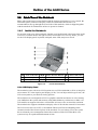
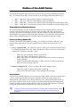
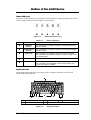
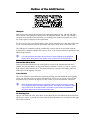
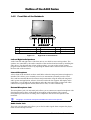
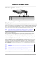
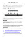
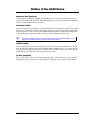
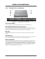
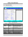
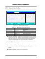
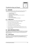
1 Chapter Outline of the A440 Series 1.1 Introduction This chapter provides the outline features and operation of the A440 Series including the BIOS Setup program and other system options. The A440 series all-in-one notebook offers the latest in advanced portable computing and multimedia technology that even outperforms most desktop computers. It incorporates the latest Intel Pentium-III Mobile Processor or Intel Celeron Mobile processor running at 100MHz Front Side Bus. It comes with a built-in Windows 95/98 keyboard, glide pad pointing device, sound system, PCMCIA slots, and advanced power management. It also includes most of the I/O ports found in today’s desktop PC including USB (Universal Serial Bus) port, Infrared (FIR), and a docking port. 1.2 Feature Highlights The A440 Series includes a variety of innovative features: Table 1-1 Feature Highlights Features CPU Description • Pentium-III Mobile Processors using Socket 370 FCPGA packaging at 650 / 700 / 750 / 800 / 850 MHz • Celeron Mobile processor using Socket 370 FCPGA packaging at 500 / 533 / 566 / 600 / 633 / 667 MHz Cache Memory • On-die secondary level cache (256-Kbyte) for Pentium-III Mobile • On-die secondary level cache (128-Kbyte) for Celeron Mobile Bus Architecture 32-bit PCI/PCI-to-ISA Bus Architecture Bus Speed 100 MHz Front Side Bus System Memory • Two memory slots for 144-pin SODIMM SDRAM (3.3V) • Uses PC-100 SDRAM (32 / 64 / 128 MB) • Upgradeable to 256MB Display • 12.1” SVGA DSTN or TFT Color LCD at 800x600 pixel resolution • 13.3" XGA TFT Color LCD at 1024x768 pixels resolution • 14.1” XGA TFT Color LCD at 1024x768 pixels resolution • Maximum 32-bit True Color display at 1024x768 pixel resolution • Brightness controls via hot-key function VGA • High Performance ProMedia CyberBladei1 2D / 3D Graphics Accelerator With AGP support (integrated in North Bridge chip) • 4 or 8 MB RAM using Shared Memory Architecture (SMA) • Up to 1024x768 resolution for external CRT monitor at 16M colors (24-bit True Color) FIC A440 Series Service Manual 1-1 Outline of the A440 Series Features HDD Description • Built-in (internal) 2.5-inch Enhanced IDE hard drive • 4.8 / 6.4 / 10 / 12 GB or above disk drive options • Supports Bus Mastering Ultra-DMA feature FDD Built-in 3.5-inch 1.44MB floppy disk drive (3-mode) CD-ROM / • Built-in ATAPI IDE 24X Speed CD-ROM drive; or DVD-ROM • Built-in ATAPI IDE 6X or 8X Speed DVD-ROM drive Keyboard • Built-in 87-key (90-keys for Japan) Windows 95/98 keyboard with 12 programmable function keys and 9 hot-key functions • Compatible with IBM enhanced 101/102-key keyboard Pointing Device • Integrated Touchpad (Glidepad) with 2 select click buttons • PS/2 mouse interface PCMCIA Slot • Double-deck PCMCIA 2.1 card slots that support two Type II or one Type III PC cards • 32-bit CardBus PCI local bus technology / Supports mixed voltage PC cards (5V and 3.3V) • Integrated ZV (Zoomed Video) Port function on top PC slot I/O Port • Includes the following standard I/O ports: 1 x 9-pin Serial Port (COM1) 1 x 25-pin Printer Port (LPT1) 1 x mini-DIN PS/2 Port (K/B or Mouse) 1 x 15-pin VGA Port (CRT) 1 x S-Video Port (TV-out) 2 x standard USB Port 1 x SIR Port (COM2) 1 x Docking Port (Port Replicator) Audio System • 16-bit full-duplex sound controller with software wavetable function and FM stereo synthesizer (integrated in South Bridge chip) • Compatible with Sound Blaster Pro • Integrated 2-way stereo speakers and mono microphone • Includes the following: Microphone-in jack (MIC-IN) Audio line-out jack Audio line-in jack Volume thumb-wheel knob control 1-2 FIC A440 Series Service Manual Outline of the A440 Series Features Power System Description • Universal Auto-switching 60W AC Adapter (100V – 240V) / Autocharging capability • Rechargeable NiMH (3800mAh/9.6V) or Li-Ion (3200mAh/14.4V) Battery Pack • NiMH Battery Life: 1.5 hours (Power Management Off) • Li-Ion Battery Life: 2 hours (Power Management Off) • Charging Time: 2.5 ~ 3 hours quick charge (computer off) Power Management • Windows APM 1.2 Compliant • ACPI and DMI 2.0 BIOS Ready • Suspend-to-RAM and Suspend-to-Disk feature / Auto Suspend hot-key function / Battery Low Auto Suspend • Cover Switch (Suspend/CRT-only) function LED Indicator 7 x LED Status Indicator for Power Source, Battery Charge, IDE, FDD, Caps Lock, Scroll Lock, Num Lock Optional Module • 56Kbps Fax/Voice/Data Internal Modem with V.90 support • 10/100Mbps Fast Ethernet Internal LAN module FIC A440 Series Service Manual 1-3 Outline of the A440 Series 1.3 System Configuration Pentium-III / Celeron Mobile CPU BIOS Flash ROM 0MB on-board Upgradeable to 256MB RAM PCI 3D / AGP Graphics Engine (VGA) External VGA Monitor Color LCD SVGA/XGA DSTN/TFT USB Interface x 2 Ports Touchpad Pointing Device USB Devices PS/2 Keyboard Memory Slot 0 32/64/128 MB SDRAM or Keyboard PS/2 Mouse Memory Slot 1 32/64/128 MB SDRAM RS-232C Peripheral Parallel Interface Printer Removable Battery PCMCIA Card Slot x 2 PCMCIA Card Built-in HDD 16-Bit Audio System Ext. Mic Audio Line-In Audio Line-Out SIR Port IR Equipped Device Mini-PCI Modem or LAN Phone Line or Network Line Docking Port Port Bar 3.5" FDD CD-ROM or DVD-ROM Figure 1-1 1-4 Serial Interface (RS-232C) System Configuration Diagram FIC A440 Series Service Manual Outline of the A440 Series 1.4 Quick Tour of the Notebook Please take a moment to become familiar with the location and purpose of every control, the LED status panel, connectors and ports, which are illustrated in this section. It is recommended to first go through the User Guide of the notebook, which is shipped together with the notebook for information on how to operate its features. 1.4.1 Inside the Notebook To open the LCD cover of the notebook, find the cover latch located at the front center of the LCD cover. Push the latch to the right to release and tilt the LCD cover up. Inside, you will see the LCD display panel, keyboard, touchpad, status LED, and power switch. Color LCD Panel Glidepad Keyboard / Email / Browser Buttons Status LED Panel Air Cooling Vent / Power Button Power/Charge LEDs Figure 1-2 Inside the Notebook Color LCD Display Panel The notebook comes with several LCD option sizes at SVGA (800x600) or XGA (1024x768) o active-matrix TFT color liquid crystal display (LCD). You can adjust and tilt (up to 180 ) the LCD screen panel to your desired viewing position. The notebook uses an integrated AGP VGA graphics controller and shares its video memory (4 or 8MB) from the system main memory using Shared Memory Architecture or SMA. All LCD models can support 16M colors or maximum 32-bit true color at 1024x768 resolution. The notebook also supports simultaneous display of the LCD with the external VGA monitor. The LCD screen also uses CCFT (Cold Cathode Fluorescent Tube) backlighting which consumes much of the electrical power of the notebook. To save battery power, the system has an advanced power management feature that switches off the LCD when there is no system activity for a predetermined amount of time. FIC A440 Series Service Manual 1-5 Outline of the A440 Series You adjust the brightness and contrast level of the LCD by pressing the display control hotkeys. You activate the hot-keys by pressing the <Fn> key along with another function key: • • • • <Fn> + <F8> Key = Increases the brightness of the LCD display <Fn> + <F9> Key = Decreases the brightness of the LCD display <Fn> + <F10> Key = Increases the contrast of the LCD display (for DSTN display only) <Fn> + <F11> Key = Decreases the contrast of the LCD display (for DSTN display only) E-mail and Internet Browser Buttons The notebook includes two special function buttons for activating the Internet e-mail and browser programs. These buttons are located on the left upper side, above the keyboard assembly. The default e-mail program always activated is Microsoft Outlook Express while the default browser program is Microsoft Internet Explorer. To enable these buttons, the EZButton Utility program should first be installed and activated during Windows startup. Power and Charge Status LED Located just in front of the palmrest assembly, you will find two LEDs for the power and battery charge status. These LEDs are positioned to be visible even if the LCD cover is closed. 1. Power / Suspend LED – lets you know if power to the system is turned on and if system is in Suspend-to-RAM mode. This LED is positioned so that you can see it on both sides whether the LCD panel is opened or closed. − − − − Turns color green when the system is powered on. Turns color amber when the battery is low (8%). Blinks when system is in Suspend-to-RAM (STR) mode. Press power button to resume operation. Lights color amber when the battery is critical (below 6%) and system will not allow to power on during cold boot. 2. Battery Charging LED – turns on to indicate the battery charging status. − − Turns color amber to indicate the battery is charging. Turns off to indicate the battery is fully charged or not charging. Power Button Press the Power button either to power on or power off the system. The Power button is also a “Smart” switch, meaning that it recognizes when the system is in Suspend mode. If in Suspend mode, pressing the Power button will bring it out of Suspend mode and resume to the system’s last state. You can also set the power button function under the CMOS Setup program to either On/Off or Suspend/Resume function. Always check the Power LED after pressing the power button to know the power status of the notebook. If you are unable to power off the system, use the power override function. Press the power button and hold it in place for four seconds. The system will then power off. 1-6 FIC A440 Series Service Manual Outline of the A440 Series Status LED Panel The Status LED Panel keeps you informed of the notebook’s current operating status. Each LED is marked with an icon to designate a system status. Figure 1-3 Status LED Panel Icons Table 1-2 Icon Status LED Panel Represents IDE Drive Access Indicates This LED will turn on when the system is accessing the hard disk drive (HDD). Diskette Drive Access This LED will turn on when the system is accessing the floppy disk drive (FDD). Caps Lock This LED will turn on when the Caps Lock key is activated. When activated, all alphabet keys type in will be in upper case or in capital letters. Scroll Lock This LED will turn on when the Scroll Lock key is activated. Num Lock This LED will turn on when the Num Lock key is activated. When activated, the embedded numeric keypad (blue print numeric keys) will be enabled. Keyboard Panel The notebook keyboard has 87-keys that provides complete emulation of a full-sized enhanced desktop keyboard. ❶ ❷ ❸ Function Keys Windows Short-cut Key Figure 1-4 FIC A440 Series Service Manual ❷ ❹ ❺ Control Keys Windows 95/98 Key Cursor Control Keys Keyboard Layout 1-7 Outline of the A440 Series The notebook keyboard is a little bit different from a standard desktop keyboard. Aside from the normal alphanumeric characters and the standard keyboard function keys, the notebook keyboard includes an embedded numeric keypad, and special function keys that activates by pressing the <Fn> key together with another key. These special function keys or “hot-keys” allows you to control and adjust some of the functions of the notebook like display controls, power saving features, and others. (1) Function Keys — Six function keys, out of <F1> through <F12>, are available on the notebook keyboard. These keys also work together with the <Fn> key to activate special functions. The following function-key combinations are pre-programmed: Table 1-3 Function Keys <Fn> Function Key Combinations Function Description <Fn> + <F3> Display toggles between three video modes, LCD, CRT, or simultaneous display on both. <Fn> + <F4> Activates Suspend-to-RAM (STR) mode. Press the power button to resume. <Fn> + <F5> Stretch the LCD display when running low-resolution modes on high-resolution LCD panel. <Fn> + <F6> Turn the system speaker to on or off. <Fn> + <F8> Increases the LCD’s brightness. <Fn> + <F9> Reduces the LCD’s brightness. (2) Control keys – <Ctrl>, <Alt>, <Fn>, and <Shift> keys are controls used in conjunction with other keys to change their functions. To use control keys, press and hold the control key while pressing another key. For example, “Press <Ctrl>+ <C>” means to hold down the <Ctrl> key and type the letter <C>. (3) Windows 95/98 keys – Use this key to activate the Start Menu of Windows 95/98. (4) Shortcut/Application key – provides quick access to shortcut menus. (This key acts like a right mouse button.) (5) Cursor Control keys – Cursor control keys let you position the cursor on the screen where you want. On the screen, the cursor is a blinking underline, block, or vertical bar depending on the application. (6) Typewriter keys – Typewriter keys (also called alphanumeric keys) are used to enter text and characters. Keys with blue print on them behave differently when combined with control keys or the <Fn> key. (7) Numeric Keypad – Pressing <NumLock> on the keyboard activates the embedded numeric keypad numbers and functions printed in blue on top of the keys. When you press <NumLock> again, the keys revert to their normal functions as typewriter keys. 1-8 FIC A440 Series Service Manual Outline of the A440 Series Figure 1-5 Embedded Numeric Keypad Glidepad Built in just below the keyboard panel is the Glidepad pointing device. The left and right select buttons of the glidepad is found below the glidepad surface. The left select button is configured (by default) as the left button you normally click on the mouse while the select key to the right is configured as the right button. To move cursor, place your finger lightly on the sensor pad and move in the desired direction. If you reach the end of the pad, lift your finger and place it back down on the other side. The Glidepad is compatible with the standard PS/2 mouse and can be activated using the normal DOS or Windows IBM or PS/2 mouse driver. You can also disable the glidepad in the BIOS Setup program. You can execute a left button click function by simply tapping on the Glidepad surface once. Refer to the User Guide of the notebook for more information. Internal Hard Disk Drive Found just underneath the left side of the palm-rest panel is the internal hard disk drive (HDD). The internal HDD is an approved industry standard 2.5-inch (12.7mm or 9.5mm) high-capacity IDE hard disk drive. The notebook likewise supports Ultra-DMA and LBA mode up to 12GB capacity or higher. Cover Switch The Cover Switch is found inside the notebook assembly just underneath the latch opening where you insert the LCD cover hook. Whenever the LCD cover is closed, it activates the Suspend mode or switches the display to CRT if there is an external monitor connected. When Suspend-to-RAM mode is activated, make sure not to leave the system for a long period when running at battery mode. The battery will continue to drain some power even in Suspend mode. It is better to save all files and shutdown the power instead or run Suspend-to-Disk mode. Air Cooling Vent The air vent allows the CPU fan to draw air into the heat pipe unit found inside the notebook. The hot air, in turn, is emitted out of the notebook through another air vent found on the right side of the notebook. FIC A440 Series Service Manual 1-9 Outline of the A440 Series 1.4.2 Front Side of the Notebook Left Speaker Internal Microphone Volume Knob Figure 1-6 Optional IR Port Line-In Port Right Speaker Microphone Port Earphone Port Right Side of the Notebook Left and Right Audio Speakers At the front left and right sides of the base unit are two built-in stereo mini speakers. The speakers are controlled by the audio controller of the notebook and activated by installing the audio driver. For adjusting the volume of the speakers, you can use the volume control program under Windows 95/98 or by adjusting the thumb-wheel volume knob also found on the front side of the notebook. Internal Microphone Also in front of the notebook are three small holes where the integrated mono microphone is installed. This allows you to instantly record voice annotations (normally saved as WAV files) and later attached them to documents and presentation using the notebook integrated audio system and application software. Since the notebook also supports full-duplex audio capabilities, you can talk to the microphone and at the same time listen to others talk when connected to a speakerphone modem, Internet live chat, or video conferencing. External Microphone Jack The microphone jack (1/8-inch mini-jack) allows you to connect an external microphone with 600-ohm dynamic in place of the built-in microphone of the notebook. The external microphone provides lesser recording noise compared to the built-in microphone of the notebook. Plugging in an external microphone disables the internal microphone. Audio Line-In Jack This jack (1/8-inch mini-jack) allows you to feed in audio signals from compact disc player, radio cassette and tape recorder. 1-10 FIC A440 Series Service Manual Outline of the A440 Series Earphone/Headphone Jack This jack (1/8-inch mini-jack) allows you to connect an external headphone, earphone, or amplified speakers for personal listening. Turn the volume level down first before placing the earphone or headphone set into your ear. Then adjust the volume according to your listening level. If you get noise feedback on the external speaker, try to lower down the volume knob on the speaker and adjust the volume using the notebook’s volume control buttons or the software. Thumb-Wheel Volume Knob Control The notebook includes a thumb-wheel volume knob to easily adjust the volume level of the built-in speakers or the external earphone/headphone set. The volume knob does not work for the Line-Out jack. You need to adjust the volume from the external speakers itself or from Windows program. IR Port (Optional) The IR port (COM2 port) provides wireless file transfer between your notebook computer and an IR-equipped computer or device. You can also print to an IR-equipped printer without connecting the printer cable. Refer to Chapter 2 on how to setup and configure the IR port driver. This feature is not available on all models. When not using the IR port, it is recommended to disable the COM2 port under BIOS Setup program to free up IRQ resource. The IR port is disabled by default. When using the IR port, make sure that there is nothing blocking the transmission. When IR is enabled, you must set the PCMCIA fax/modem to COM3 or COM4 instead since COM2 has already been used. FIC A440 Series Service Manual 1-11 Outline of the A440 Series 1.4.3 The Right Side of the Notebook Battery Pack Internal Modem or LAN Kensington Lock Figure 1-7 PCMCIA Slots Air Vent Exhaust Right Side of the Notebook Battery Compartment The battery compartment stores the Nickel Metal-Hydride (NiMH) or Lithium-Ion (Li-Ion) battery pack for off-the-cord operation. The battery pack is instantly charge whenever you connect the AC adapter to the notebook. It is very important to always have the battery installed on the notebook to have it always charged and conditioned by the AC adapter. Normal operating time using NiMH battery pack is close to 2 hours while Li-Ion battery pack can take more than 2.5 hours. For new battery packs or for battery packs that are not used for a certain time, you may need to fully discharge and recharge the battery for several times. PCMCIA Slot Compartment The PCMCIA slot compartment houses two card slots that support two PCMCIA Type II cards at the same time or one Type III card. The notebook uses a CardBus PCMCIA controller that supports 5V and 3V 32-bit CardBus and 16-bit PC cards including cards with Zoomed Video (ZV) function like MPEG PC cards. The PCMCIA slot compartment comes with vertical sliding doors so you can directly insert the PC card. If you are using a Type III card, insert the Type III card into the top slot. To remove the inserted PC card, slightly push the button found on the left side of the PC slot to release the eject button. Then push it again to release the PC card. The upper left button releases the card on the top slot while the lower left button releases the card on the bottom slot. When the PC card has moved out a space out of the slot, hold the edges of the card and slowly slide it out. For ZV function PC cards, insert it only into the upper slot. The bottom slot does not support it. For full functionality of PC cards, always ask for the latest driver from your PCMCIA card dealer or download it from their Internet website. For network PC cards, you need first to stop the device under the PC Card properties of Windows 95/98 Control Panel. Otherwise, this may cause system hang or system fatal error. 1-12 FIC A440 Series Service Manual Outline of the A440 Series Modem /LAN Port The modem/LAN port provides a reserve jack for installing an internal modem with RJ-11 jack or internal LAN module with RJ-45 jack. The internal modem is a 56Kbps-fax/data PCI modem and supports the latest V.90 standard. The internal LAN module is a 10/100Mbps Fast Ethernet PCI module. Only one module can be fitted in and is not user-upgradable. The internal module uses mini-PCI technology. It is sort of a PCI add-in card reduced into a smaller compact form. The internal module is inserted into the mini-PCI socket found on the underside of the notebook. CPU Fan Exhaust The exhaust vent allows the CPU fan inside to emit the heat out of the notebook and keep it within operating temperature. Security Lock Latch This latch allows you to attach a Kensington security lock or other compatible lock for securing the notebook from theft. It is found on the corner near the rear side of the notebook. 1.4.4 The Left Side of the Notebook USB Ports CD-ROM or DVD-ROM Drive Figure 1-8 FDD Drive Left Side of the Notebook USB (Universal Serial Bus) Ports . This 4-pin The USB (Universal Serial Bus) Port is a new generation port and has the symbol slim port allows you to connect multiple USB devices through daisy chaining or through a USB hub and use them all simultaneously. The USB specification states it can support up to 127 USB devices running at up to 12Mbps. This notebook provides two USB ports. When you resume the system from suspend mode, the USB port may not initialize properly. If in case the USB device does not work, unplug and plug the USB device again. This is a known bug released by Intel and Microsoft Windows. Built-in CD-ROM or DVD-ROM Drive The notebook comes with a standard 24X-speed ATAPI IDE CD-ROM drive that supports all major CD formats like CD-R, Photo CD, and Video CD. The drive utilizes a pop-out tray loading mechanism and supports bootable CD by setting the BIOS Setup program. Refer to Chapter 2 on how to install the CD-ROM driver. The notebook also comes with a 6X or 8Xspeed DVD-ROM drive option. FIC A440 Series Service Manual 1-13 Outline of the A440 Series Built-in Floppy Disk Drive (FDD) The built-in FDD allows you to use any standard double-sided high-density (DSHD) diskette for copying and transferring data files. The notebook also comes with a 3-mode driver for 1.2MB diskette normally used in Japan. In the BIOS Setup program of the notebook, you also have the option to disable the FDD or set a password option when accessing the drive. 1.4.5 The Rear Side of the Notebook PortBar Notch Serial Port VGA Port Figure 1-9 AC Power Port Docking Port TV Port PS/2 Port Printer Port PortBar Notch Upper Rear Side of the Notebook PortBar Notches Use this notch to secure the PortBar to the back of the system. There are two PortBar notches located at the both ends of the rear side of the system. AC Power Port Lets you attach the notebook to the AC power source using the AC adapter that comes with your system. Keep the system connected to AC power whenever possible to keep the battery pack and internal CMOS battery charged. The Battery Charge LED will activate whenever the battery is being recharged. PS/2 Port Use the standard PS/2 port to connect an external PS/2-style mouse, PS/2-style keyboard, or PS/2 style Numeric Keypad to the system. With an optional Y-cable adapter, you can connect any combination of two of these devices at the same time. For non-PS/2 keyboard, you need to use a keyboard adapter that converts the DIN-type connector to PS/2 connector. Serial Port (COM 1) The 9-pin serial port provides a serial interface to which you can connect an RS-232C device such as external serial mouse or modem. This port is commonly referred to as COM1. When connecting an external serial mouse, you must first power off the system before connecting the external mouse. You can auto-detect the serial mouse hardware and run both glidepad and serial mouse simultaneously. Whenever using an external mouse in place of the built-in glidepad, it is recommended to switch the mouse driver to the default standard Microsoft mouse driver. 1-14 FIC A440 Series Service Manual Outline of the A440 Series Expansion Port (Optional) Use this port to connect the PortBar. The PortBar is an accessory that duplicates the ports found on the back of the notebook. Keep the PortBar in your office connected to peripherals while you take the notebook on the road. Printer Port (LPT1) The printer port lets you connect a 25-pin parallel device such as printer, pocket LAN adapter, ZIP drive, or remote data transfer cable. Many operating systems and software applications refer to this port as LPT1. You can run the BIOS setup program to change the configuration of the parallel port to Bi-directional or ECP (Extended Capabilities Port) mode. Some older parallel devices may not function with the ECP default setting. You need to run the BIOS Setup program to adjust the settings. VGA Port (CRT) The VGA port lets you connect an external VGA (CRT) monitor to the notebook. You can also run the LCD and the external CRT monitor display simultaneously; or switch it to CRT only using the function hot-key (Fn+F3). When switch to CRT only, you can set the display resolution up to 1024x768 at 16M colors (24-bit true color). TV Port (Optional) The TV port allows you to connect the notebook to the S-Video connector of your TV and output display for presentation or video playback. This port is not available on all models. FIC A440 Series Service Manual 1-15 Outline of the A440 Series 1.4.6 The Under Side of the Notebook / / / Tilt Foot Battery Compartment / Latch Figure 1-10 Internal Module Compartment Memory Compartment The Under Side of the Notebook Tilt Foot (Left and Right) Allow you to tilt the rear of the notebook upward for more comfortable typing. Modem/LAN Module (Mini-PCI Socket Compartment) This compartment houses the mini-PCI socket for inserting the internal modem or LAN module. When upgrading the internal module to either LAN or modem, it is also required to change the cable. Refer to Chapter 2 for installing the Modem/LAN module. Battery Bay Also found on the underside of the notebook is the battery bay where the battery pack is attached. Battery Bay Latch Also found on the underside of the notebook is the battery bay latch. To remove the battery pack, you need to push this latch and at the same time pull the battery pack. Memory Compartment Found on the underside of the notebook is the memory compartment. Underneath the cover are two 144-pin SODIMM memory slots for inserting and upgrading the system memory using 32MB, 64MB, and 128MB SODIMM. The notebook uses PC-100 SDRAM modules for faster memory access. You can upgrade the total memory up to 256MB. One is inserted with a SDRAM configured by the factory. The other is empty for upgrade use. Refer to Chapter 2 on how to upgrade the system memory. 1-16 FIC A440 Series Service Manual Outline of the A440 Series 1.5 System BIOS SETUP Program The notebook uses the Phoenix BIOS Setup program that allows you to set several system configurations in changing the way the system performs. This includes your system time and date, disk drive configuration, I/O device controls, boot drive sequence, and power management settings. The information is then stored in the CMOS RAM chip and will remain permanent unless you change it again. The notebook also uses EPROM Flash BIOS that allows you to update the system BIOS by simply overwriting it using the Phoenix Flash programming utility. Before boot-up, the system will read the BIOS settings and compare them to the equipment check conducted during the POST (Power-On Self-Test). If an error occurs, an error message will be displayed on the screen, and you will then be prompted to run the BIOS Setup Program. Press the <F2> key to run the BIOS Setup program. The BIOS Setup program is organized into six menus which you can select using the < > and < > keys. To move from one option to another, you use the up and down arrow keys. On the BIOS Setup program, you will find the following parts on the screen: • Menu Bar - found on the top line of the screen. Each of the six items has a separate menu screen. • Parameters - found on the left side of the screen. This area lists the parameters and their current settings. • Item Specific Help - found on the right side of the screen. This area describes each parameter and its available settings. • Key Legend - the bottom part of the screen. These lines display the keys available to move the cursor, select a particular function and so forth. The following table lists the keys on how to edit and move around the setup menus inside. Table 1-4 BIOS Setup Control Keys KEY WHAT IT DOES <F1> Shows on-line help on key functions. ↑ ↓ Moves the cursor between the displayed parameters. <+> / <-> Modifies the current parameter settings. <F9> Load default configuration. Tab, Shift-Tab or Enter For some parameter settings, moves the cursor between the subfields. Also moves the cursor to the next line or selection. Esc Exits the current menu and returns to the main menu or go directly to the Exit menu. Changes between displayed menus. <F10> Save changes and exit. Some information here may not be available or different from other date code versions of the notebook BIOS. Always check for the latest BIOS update from the FIC Internet homepage. FIC A440 Series Service Manual 1-17 Outline of the A440 Series 1.5.1 Using the Main Menu The BIOS Setup Main Menu contains the settings for system time and date, and disk drives as well as CPU and system memory information. PhoenixBIOS Setup Utility Main Advanced Security Power Saving Boot Exit Item Specific Help 4 F1 System Time: [12:00:00] <Tab>, <Shift-Tab>, or System Date: [07/01/2000] <Enter> selects field. Language: [English (US)] Diskette A: [1.44/1.25 MB, 3½”] Internal HDD: [6007MB] Internal DVD/CD-ROM: [Installed] Boot Display Device: [Both] System Memory: 640 KB Extended Memory: 56320 KB CPU Type Celeron (TM) CPU Speed 600 MHz BIOS Version 1.0A-5705-2000 Help Esc Exit K Select Item -/+ Change Values F9 st Select Menu Enter Select 4Sub-Menu F10 Save and Exit Figure 1-11 Table 1-5 System Time: Setup Defaults BIOS Setup Main Menu BIOS Setup Parameters, Default and Alternate Settings [12:00:00] <Tab>, <Shift-Tab>, or <Enter> selects field. System Date: [07/01/2000] <Tab>, <Shift-Tab>, or <Enter> selects field. Language: [English (US)] Select the display language for the BIOS. Diskette A: [Disabled] / Select floppy type. Note that 1.25 MB references a 1024-byte/sector Japanese media format. The 1.25 MB, 3½” diskette requires a 3-Mode floppy-disk drive. [1.44/1.25 MB, 3½”] Internal HDD [6007MB] Internal DVD / CDROM Installed (BIOS auto detect, for information only) Boot Display Device: [Both] / [CRT] / [LCD] Choose the display device. System Memory 640 KB (BIOS auto detect, for information only) Extended Memory 56320 KB (BIOS auto detect, for information only) CPU Type Celeron (TM) (BIOS auto detect, for information only) CPU Speed 600MHz (BIOS auto detect, for information only) BIOS Version 1.0A-5705-2000 (BIOS auto detect, for information only) 1-18 FIC A440 Series Service Manual Outline of the A440 Series System Time – To set the time, enter the current hour, minute, and second on hr/min/sec, 24-hour format. System Date – This field lets you set the calendar month, day, and year. The calendar clock is year 2000-compliant and remains in memory even after you turn off the system. Language – This field lets you set the type of language for the BIOS display. Diskette Drive A – This field allows you to enable or disable the built-in 1.44/1.25MB 3½ ” Diskette. Internal HDD – This field displays various parameters for the hard disk drive. If type [Auto] is selected, the system automatically sets these parameters. If type [User] is selected, Cylinders, Heads and Sectors can be edited. Internal DVD/CD-ROM – This field displays various parameters for the internal CD-ROM or a DVD-ROM Drive. Boot Display Device – This field allows you to set the output boot display to the LCD, CRT, or Both. System Memory, Extended Memory, CPU Type, CPU Speed and BIOS Version – These fields are for information only as the BIOS automatically detects related values. PhoenixBIOS Setup Utility Main Internal HDD [6007MB] Item Specific Help Type: Cylinders: [Auto] [12416] Select the drive type corresponding to the Heads: [15] fixed disk installed in Sectors: [63] your system. Maximum Capacity: 6007MB If type USER is selected, Cylinders, Multi-Sector Transfers: [16 Sectors] Heads & Sectors are LBA Mode Control: [Enabled] edited directly. 32 Bit I/O: [Disabled] Transfer Mode: [FPIO 4 / DMA 2] Ultra DMA Mode: [Mode 4] Help K Esc Exit F1 + Select Item −/+ Change Values F9 Setup Defaults Select Menu Enter Select F10 Save and Exit Figure 1-12 FIC A440 Series Service Manual Sub-Menu Internal HDD/CD-ROM Sub-Menu 1-19 Outline of the A440 Series Table 1-6 Internal HDD / Internal CD-ROM Sub-Menu Options Type: [None] / [CD-ROM] / [User] / [Auto] Select the drive type corresponding to the fixed disk installed in your system. If type USER is selected, Cylinders, Heads & Sectors edited directly. Cylinders: [10068] (BIOS auto detect, for information only) Heads: [15] (BIOS auto detect, for information only) Sectors: [63] (BIOS auto detect, for information only) Maximum Capacity: 4871MB (BIOS auto detect, for information only) Multi-Sector Transfers: [Disabled] / [2 Sectors] / [4 Sectors] / [8 Sectors] / [16 Sectors] Determine the number of sectors per block for multiple sector transfers. LBA Mode Control: [Disabled] / [Enabled] Enabling LBA causes Logical Block Addressing to be used in place of Cylinders, Heads & Sectors 32 Bit I/O: [Disabled] / [Enabled] This setting enables or disables 32 bit IDE data transfers Transfer Mode: [Standard] / [Fast PIO 1] / [Fast PIO 2] / [Fast PIO 3] / [Fast PIO 4] / [FPIO 3 / DMA1] / [FPIO 4 / DMA2] Select the method for moving data to/from the drive. Autotype the drive to select the optimum transfer mode Ultra DMA Mode: [Mode 2] (BIOS auto detect, for information only) 1-20 FIC A440 Series Service Manual Outline of the A440 Series 1.5.2 Using the Advanced Menu The Advanced Menu allows you to configure the OS and I/O device settings. PhoenixBIOS Setup Utility Main Advanced Security Power Saving Boot Exit Item Specific Help 4 F1 BootUp Num-Lock: [LockOff] Selects Power-on state PS/2 Mouse [Auto] for NumLock Installed O/S: [Win98/Win2000] LCD Panel View Expansion: [Enabled] Silent Boot [Enabled] Aperture Size: [64 MB] Frame Buffer Size: [8 MB] I/O Device Configuration Help Esc Exit K Select Item F5/F6 Change Values st Select Menu Enter Select Figure 1-13 Table 1-8 Sub-Menu F9 Setup Defaults F10 Save and Exit BIOS Setup Advanced Menu BIOS Setup Advanced Menu Options BootUp Num-Lock: [LockOn] / [LockOff] Selects Power-on state for NumLock PS/2 Mouse: [Disabled] / [Both] / [Auto] [Disabled] prevents any installed PS/2 mouse from functioning, but frees up IRQ12. [Both] allows both internal and external PS/2 mouse to be active. [Auto] will only allow the external PS/2 mouse to be active if it is detected. Installed O/S: [Other] / [Win98/Win2000] Select the operating system installed on your system which you will use most commonly. Note: An incorrect setting can cause some operating systems to display unexpected behavior. LCD Panel View Expansion: [Disabled] / [Enabled] [Disabled] – Reduces the panel view in some video mode [Enabled] – Expands the panel view, but it may adversely affect the graphic/text quality Silent Boot: [Enabled] / [Disabled] / [Black] Select boot screen using options: [Enabled] – Logo screen on boot [Disabled] – POST screen on boot [Black] – Black screen on boot Aperture Size: [4MB] / [8MB] / [16MB] / [32MB] / [64MB] / [128MB] Virtual address use for VGA Frame Buffer Size: [4MB] / [8MB] Video memory size. FIC A440 Series Service Manual 1-21 Outline of the A440 Series Submenu 4I/O Device Peripheral Configuration Configuration BootUp Num-Lock – Allows you to set the power-on state for the <NumLock> key. Set this to [LockOn] if you want to enable <NumLock> during power on. PS/2 Mouse – [Disabled] prevents any installed PS/2 mouse from functioning, but frees up IRQ12. [Both] allows both internal and external PS/2 mouse to be active. [Auto] will only allow the external PS/2 mouse to be active if it is detected. Installed O/S – Set this option to [Win98/Win2000] if you are installing a Windows operating system. Otherwise, set this option to [Other]. LCD Panel View Expansion – Allows you to expand the display according to the panel resolution of the LCD. Silent Boot – Select boot screen during POST. Aperture Size – Allows you to set the aperture size of the VGA. Frame Buffer Size – You can set to either 4MB or 8MB. Uses Shared Memory Architecture (SMA) so this video memory will be taken from the system main memory. I/O Device Configuration – Lets you configure input/output device such as Serial Port, Parallel Port, and Floppy disk controller. PhoenixBIOS Setup Utility Advanced I/O Device Configuration Item Specific Help Serial port: Base I/O address: [Enabled] [3F8 IRQ4] Configure serial port using options: Parallel port: [Enabled] [Disabled] Mode: [Uni-irectional] Base I/O address: [378] No configuration [Enabled] Floppy disk controller: [Enabled] User configuration [Auto] BIOS or OS chooses configuration Help K Esc Exit st F1 + Select Item −/+ Change Values F9 Setup Defaults Select Menu Enter Select F10 Save and Exit Figure 1-14 1-22 Sub-Menu I/O Device Configuration Sub-Menu FIC A440 Series Service Manual Outline of the A440 Series Table 1-9 Serial port A I/O Device Configuration Sub-Menu Options [Disabled] / [Auto] / [Enabled] Configure serial port A using options: Disabled - No configuration, Enabled - User configuration, Auto - BIOS or OS configuration. Base I/O address Parallel port [3F8 IRQ4] / [2F8 IRQ3] / [3E8 IRQ4] / [2E8 IRQ3] Set the base I/O address for serial port A. [Disabled] / [Auto] / [Enabled] Configure parallel port using options: Disabled - No configuration, Enabled - User configuration, Auto - BIOS or OS configuration. Mode [Uni-directional] / [ECP] / [Bi-directional] Set the mode for the parallel port using options. Base I/O address [378] / [278] / [3BC] Select the base I/O address for the parallel port when port is Enabled. DMA channel [DMA 0] / [DMA 1] Set the DMA channel for the ECP mode. [Disabled] / [Enabled] Configure the floppy disk controller using options: Floppy disk controller Disabled - No configuration, Enabled - User configuration If you disable a device in Setup, you cannot enable or assign it using the Windows (95 or 98) Device Manager. The device is not listed in the Windows device list. You need to select any setting other than “Disable” in Setup. FIC A440 Series Service Manual 1-23 Outline of the A440 Series 1.5.3 Using the Security Menu The Security menu allows you to set the system password as well as disk-protection security. PhoenixBIOS Setup Utility Main Advanced Security Power Saving Boot Exit Item Specific Help Set Supervisor Password Set User Password [Enter] [Enter] Supervisor Password controls access to the setup utility. F1 Password on boot: [Disabled] Fixed disk boot sector: [Normal] Diskette access: [Supervisor] Help Esc Exit K Select Item -/+ Change Values st Select Menu Enter Select Sub-Menu Figure 1-15 Table 1-11 F9 Setup Defaults F10 Save and Exit BIOS Setup Security Menu BIOS Setup Security Menu Options Set Supervisor Password Press Enter Supervisor Password controls access to the setup utility. Set User Password Press Enter User Password controls access to the system. Password on boot [Disabled] / [Enabled] Enabled password entry on boot Fixed disk boot sector [Normal] / [Write protect] Write protects boot sector on hard disk, to protect against viruses. Diskette access [User] / [Supervisor] Control access to diskette drives. Set User Password – Specifies if the system prompts you to enter a password when accessing the system. The Set User Password function will be enabled once a Supervisor password is set. Enter a new password with up to eight alphanumeric characters, and then enter this same new password again for confirmation. Set Supervisor Password – Specifies if the system prompts you to enter a password when entering Setup. Password on boot – Enables password check when booting. Fixed disk boot sector – [Write Protect] enables write protect boot sector on hard disk to prevent against viruses. [Normal] disables this write protect function. Diskette access – Controls access to diskette drive. 1-24 FIC A440 Series Service Manual Outline of the A440 Series 1.5.4 Using the Power Menu The Power setup menu lets you balance high performance and energy conservation using parameters including the following. PhoenixBIOS Setup Utility Main Advanced Security Power Saving Boot Exit Item Specific Help Power Switch Resume On Modem Ring: [On/Off] [Off] Resume On Time: [Off] Behavior of the power switch. F1 Help K Select Item +/− − Change Values F9 Setup Defaults Esc Exit st Select Menu Enter Select Sub-Menu F10 Save and Exit Figure 1-16 Table 1-11 BIOS Setup Power Menu BIOS Setup Power Menu Options Power Switch [On/Off] / [Suspend/Resume] Behavior of the power switch. Resume On Modem Ring [Off] / [On] Enabled wakes the system up when an incoming call is detected on your modem. Resume On Time [Off] / [On] Enabled wakes the system up at a specific time. Resume Time [Hour:Minute:Second] Specify the time when system is to wake up. <Tab., <Shift-Tab>, or <Enter> selects field. Power Switch – Select the behavior of the power switch. Resume On Modem Ring – [On] will wake the system up when an incoming call is detected on your modem. Resume On Time – [On] will wake the system up at a specific time. Resume Time – Specifies the time when system is to wake up. This option is only available when the Resume On Time is set to [On]. Some operating systems, like Windows 98 or Windows 2000, have their own power management software that overrides the CMOS settings. In this case, use the power management settings provided by Windows 98 or Windows 2000. FIC A440 Series Service Manual 1-25 Outline of the A440 Series 1.5.5 Using the Boot Menu The Boot menu lets you decide the boot order of booting devices including: PhoenixBIOS Setup Utility Main Advanced Security Power Saving Boot Exit Item Specific Help + + Removable Devices Hard Drive Use <K K> or < > to select a ATAPI CD-ROM device, then press <+> or <-> to move the device up or down. <Enter> expands or collapses device. <Ctrl+Enter> expands all. F1 Help K Select Item -/+ Change Values F9 Esc Exit st Select Menu Enter Select Sub-Menu F10 Save and Exit Figure 1-17 Setup Defaults BIOS Setup Boot Menu Removable Devices – put this option on top if you want to boot from a bootable floppy diskette (Drive A:\). Hard Drive – put this option on top if you want to boot from a bootable hard disk drive (Drive C:\) ATAPI CD-ROM Drive – put this option on top if you want to boot from a bootable CD-ROM like Windows NT (Drive D:\). 1-26 FIC A440 Series Service Manual Outline of the A440 Series 1.5.6 How to Exit the Setup Program There are three choices to escape from the Setup program. PhoenixBIOS Setup Utility Main Advanced Security Power Saving Boot Exit Item Specific Help Exit Saving Changes Exit Discarding Changes Exit System Setup and save your changes to Load Setup Defaults CMOS. Discard Changes Save Changes Battery Refresh F1 Help Esc Exit K Select Item -/+ Change Values F9 st Select Menu Enter Select Sub-Menu F10 Save and Exit Figure 1-18 Setup Defaults BIOS Setup Exit Menu Exit Saving Changes – Exits System Setup and saves your changes to CMOS. Exit Discard Changes – Exits Setup utility without saving Setup data to CMOS. Load Setup Defaults – Loads the default settings for all items in Setup. Discard Changes – Reverts to previously selected settings and exits Setup. Save Changes – Saves Setup data to CMOS. Battery Refresh – Drains and refreshes the battery. This option is only for NiMH battery. FIC A440 Series Service Manual 1-27 Outline of the A440 Series 1.6 Notebook Accessories and System Options It is also important to understand the accessories that come along with the notebook and the options for fully utilizing the capabilities of the computer. This section describes briefly what these accessories and options are. 1.6.1 AC Adapter and Power Cord The AC Adapter supplies external power to your computer and at the same time charges the internal battery pack. The AC adapter has an auto-switching design that can connect to any 100VAC ~ 240VAC power outlets. Connect the adapter to the AC wall outlet using the power cord. There is an LED on the AC adapter to indicate if DC power is already available. 1.6.2 Battery Pack Aside from the AC adapter, your computer can also be powered through the removable battery pack. The battery pack uses rechargeable Nickel-Metal Hydride (NiMH) or LithiumIon (Li-Ion) battery cells that can run for 2.5 to 3 hours when fully charged and power management enabled. Recharging the battery takes around 2.5 to 3 hours when the computer is off. You should always leave the battery inside your computer even when using the AC adapter as it also acts as back-up power supply in case power from the AC adapter is cut off. It is also very important to have the battery pack always charged to prevent battery cell degradation. If the AC adapter is not connected or not available, and the notebook is not going to be used for some period, it is advisable to remove the battery pack from the notebook to prevent any current leak. 1.6.3 Internal Modem Module Card The notebook allows you to insert a proprietary internal 56Kbps-modem card to the notebook found on the underside of the notebook. The internal modem card supports only fax and data communication and is V.90-compliant. You connect the telephone line to the RJ-11 jack found on the right side of the notebook. 1.6.4 Internal LAN Module Card The notebook also provides an internal 10/100Base-T Ethernet LAN module card in place of the internal modem. The reserve LAN/Modem port can fit either a RJ-11 or RJ-45 jack. 1.6.5 DVD-ROM Drive Other than the internal CD-ROM drive, the notebook also provides an optional DVD-ROM drive that plugs into the same Secondary Master IDE interface of the CD-ROM drive. The DVD-ROM drive is backward compatible with the CD-ROM drive aside from being capable of reading and playing DVD disc. Using a software MPEG-2/DVD program, the notebook can playback any commercial DVD movie titles. There are some patent restrictions, however, when you want to playback the DVD into your TV set. 1.6.6 PortBar The PortBar is an accessory that duplicates the ports found on the back of the notebook. Keep the PortBar in your office connected to peripherals while you take the notebook on the road. 1-28 FIC A440 Series Service Manual


![UK User`s Manual [ Notebook ]](http://vs1.manualzilla.com/store/data/005694610_1-ad8e24898a53e900e9c2a73fa8f500a7-150x150.png)