1
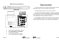
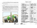
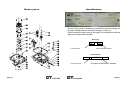
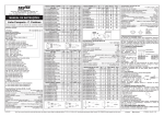
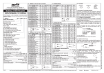
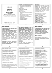
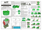
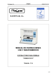
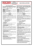
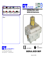
RIVENDITORI
AUSTRALIA
Acrodyne Pty Ltd.
Factory 14-11 Havelock Road
P.O.BOX. 640-Bayswater
3153 Victoria
http://www.acrodyne.com
GERMANY-BENELUX
Bar GmbH
Auf der Hohl - D
53547 Dattenberg
http://www.bar-gmbh.de
E-mail:[email protected]
DENMARK
Dansk Ventil Center
Dandyvej 5
7100 Vejle Denmark
http://www.danskventilcenter.dk
E-mail:[email protected]
SPAIN
IMI Norgren s.a.
Calle Aire, 3
Pol.Ind.Els Bellots
08227 Terrassa
E-mail:[email protected]
CHINA SINGAPORE
Andy Goh
Anson Rd #12-16
International Plaza
079903 Singapore
E-mail:[email protected]
GREECE
M.G. Chryssafidis s.a.
Agrinion Str. 3
Tauros 17778
http://www.chryssafidis.gr
E-mail:[email protected]
UNITED KINGDOM
FRANCE
Meca Inox Groupe Sgd
32 Rue des Routis
60850 Le Coudray St.Germer
http://www.meca-inox.tm.fr
E-mail:[email protected]
Pacific Valves Co. Ltd.
Unit.14 - Parkside Ind.Est. Edge
Lane Street Royton - Oldham Ol2 6DS
http://www.pacific-valves.co.uk
E-mail:[email protected]
USA
Unitorq
2825 Pacific Drive
Norcross, Ga 30071 - U.S.A.
http://www.unitorq.com
E-mail:[email protected]
SWEDEN
Ventim Venil & Instruments AB
Flygplatsvagen 19
39241 Kalmar
http://www.ventim.se
E-mail:[email protected]
ISO 9001:2000- Cert. n° 0210/3
OPERATION AND
SERVICE MANUAL
Notes:
G.T. ATTUATORI S.r.l.
Viale Europa, 17 20090 Cusago MI ITALY
Tel. +39 2 903.903.22 Fax +39 2 903.903.68
http://www.gtrevisan.it
E-mail:[email protected]
CESI 03 ATEX 302
II 2 GD
EExd IIB IP66 T85 °C
SIGNAL BOX BEP
Edition 04 of 04/2005
Certificate of conformity
ATEX 94/9/CE
Notes:
(Example of connection with two inductive sensors)
BEP-I2 (Pepperl+Fuchs inductive sensors)
Summary
Introduction .............................................................. 2
Generality ................................................................. 3
Warnings .................................................................. 4
Safety and caution general conditions ........................... 5
Putting out of service ................................................. 6
Installation ................................................................ 7
Adjustment ............................................................... 8
Identification ........................................................... 11
Technical data ......................................................... 12
Lay-out .................................................................. 13
Spare parts ............................................................ 14
Safety instructions ................................................ 16
Description ............................................................. 16
Electric features ...................................................... 16
Marking ................................................................. 16
Safety instructions for the installation
in dangerous areas ................................................ 17
Suitability of the GT BEP Box for the installation
site areas with presence of gases, inflammable
vapours or fogs and dusts ........................................ 17
Cable inputs ............................................................ 18
Ground connection .................................................. 18
Checks and maintenance of the
explosion-proof boxes ............................................... 19
Electrical connections ............................................ 20
BEP-M2 ................................................................. 20
BEP-M4 ................................................................. 21
BEP-I2 ................................................................... 22
BEP-I4 ................................................................... 23
BEP-I2 ................................................................... 24
Page 24
Page 1
Introduction
BEP-I4
Kind Customer,
We at G.T. Attuatori congratulate You for preferring us in the
choice of your new accessories.
G.T. Attuatori has been for a long time in pneumatic actuators
field, in which we distinguished for manufactoring accuracy by
using the most advanced mechanical technologies.
Our Technical Office staff developes solutions for installations
problems by using superior level software, optimizing the projects
according to all kind of sollecitations involved in machinery
operation.
The G.T. Attuatori BEP-BOX is characterized by its “complete” and “essential” structure, wich allows a quick and safe use,
assuring high performance and precision, being manufactured
by using selected, high fidelity and long duration components
and materials.
1.
2.
4.
5.
6.
8.
Supply of “C” sensor 10÷60 VDC max. 200mA
“C” negative ground
PNP positive output for user
Supply of “D” sensor 10÷60 VDC max.200mA
“D” negative ground
PNP positive output for userper utilizzatore
In the version with four micro-switches, an additional card for the
eventual control of an electro-valve is introduced
Additional card
Page 2
Page 23
Generality
BEP-I2
Board BEP-I2 connection
1.
2.
3.
4.
5.
6.
Page 22
Common “C” micro-switch max. ~250V 5A
N.O. (normally open) “C” micro-switch
N.C. (normally closed) “C” micro-switch
Common “D” micro-switch
N.O. (normally open) “D” micro-switch
N.C. (normally closed) “D” micro-switch
The GT BEP explosion-proof indicating box conceived and constructed according to the Directive ATEX 94/9/CE with reference to the
European Standard EN 50014 (general requirement), EN 50018 (“d”
explosion-proof boxes) and EN 50281-1-1 (electrical constructions
destined to environments in which there are combustible dusts) is installed on a rotating pneumatic actuator, mounted on a ball valve, butterfly valve, male valve, roller shutter valve or on a mechanical organ
which requires a position indication and, as a consequence, an electrical signal.
Made by die-cast aluminium and painted with epoxy-polyester
powder, the signal Boxes of G.T. ATTUATORI have the possibility to be
adjusted in height towards the upper surface of the actuator.
Usable without distinction with shafs having protrusion over the actuator
top of 20mm.(NAMUR 20), 30mm.(NAMUR 30), 40mm.and
50mm.(NAMUR 50), due to the possibility of easy adjustment by fixed
steps, obtainable simply changing the position of the screws which fasten
the feet-brackets on the box body.
Other peculiarity of BEP-BOX is the possibility to easily self-adapt
to the two different top drillings required by NAMUR standard for the
fixing of the box to the actuator body that are mm.30x80 or mm. 30x130,
with the simple reversal of the two feet-brackets from left to right and
vice versa.
The adjustment of the switches control cams is done by two screws
which allow a fine positioning of same cams with a system to unblock
and block them against unintentional rotation.
The terminal boards are pull-out type to make easier the cables
connection.
All G.T. Attuatori boxes may be provided with the patented
tridimensional indicator “Perry” visible by the top and by the side.
Cams command rod and all the fasteners are in stainless steel.
Page 3
Warnings
BEP-M4
The installation and the starting up of the BEP-BOX have to be
done as described on following instructions.
The device can be put in service only by personnel which know
the contents of these instructions.
Pnematic actuators pruduce a strong torque consequently
during the installation and the staring up must be observed
safety instructions to avoid possible injuries.
Before to open the box cover be sure that power has been
previously switched off.
Strongly screw in the screws UNI 5931 in AISI 304 which close
the cover before the staring up.
Take care that may be present residual electrostatic charge.
For cleaning use damp cloth only.
Besides the ground connection foreseen inside the box, the
latter is equipped with a second externally positioned ground
connection.
BEP-M4 additional bord connections
1.
2.
3.
4.
5.
6.
Page 4
Common “C” micro-switch max. ~250V 5A
N.O. (normally open) “C” micro-switch
N.C. (normally closed) “C” micro-switch
Common “D” micro-switch
N.O. (normally open) “D” micro-switch
N.C. (normally closed) “D” micro-switch
Page 21
Electrical connections
CAUTION: To be sure that power is switched off before
to proceed with electrical connections.
BEP-M2
Safety and caution
general conditions
The same construction of the box is practically the protections
agaist all the parts in motion all placed inside the box.
Possible damaged power cable must be replaced !
For all the works regarding installation, starting up, equipping,
use, utilization and using mode modifications, ordinary maintenance
and inspections must be followed the putting out of service
procedures specified in this Operator’s manual.
The Operator’s manual must be always to hand, in order to
have the possibility to look it up to verify correct operating cicle
every time there are doubts or it is necessary a new setting up.
Board BEP-M2 connections
1.
2.
3.
4.
5.
6.
Page 20
Common “A” micro-switch max. ~250V 5A
N.O. (normally open) “A” micro-switch
N.C. (normally closed) “A” micro-switch
Common “B” micro-switch
N.O. (normally open) “B” micro-switch
N.C. (normally closed) “B” micro-switch
Page 5
Putting out of service
Whenever it is requested to put out of service the box, it is
necessary to follow some basic rules able to protect the
operator health and the environment too.
Sheaths, flexible tubes and plastic materials, or in any case
non metallic parts, must be disassembled and disposed
separately.
Pneumatic and electrical components as valves, solenoid
valves, switches and transformers, if any, sould be
disassembled to be re-used if in good conditions otherwise to
be overhauled and recycled when possible.
Metal parts sould be disassembled and grouped together by
metal type to be casted again in order to allow the recycling of
the materials forming the box.
Checks and maintenance of the
explosion-proof boxes
The BEP BOX needs no extraordinary maintenance. In fact,
inside it, there are no organs which need it.
When it is necessary to open the box, unscrew the 8 fixing
screws.
ONLY AFTER CUTTING THE VOLTAGE
The terminals of the electrical connections must be strictly
tightened to avoid high contact resistance and
consequent overheating
The cover must be strictly tightened and blocked against
the loosening of the suitable locking screw
The replacement of fittings and parts of the cable inputs
must be carried out using identical components to those
supplied by the manufacturer in order to guarantee a
suitable protection
The surfaces of the explosion-proof joints must not be
modified and no seals must be introduced different from
those supplied by the manufacturer. These surfaces must be
kept clean.
When substituting the clamping screws please make sure
you use screw type A2-70 UNI 5931
Page 6
Page 19
Cable inputs
Installation
The connections must be made by means of cable inputs or piping complying
with the standard EN 60079-14.
The cable input must be made so as not to alter the specific properties of the
protection mode as it is indicated in the standard EN 50018 (paragraphs 13.1
and 13.2) for the EEx-d boxes (explosion-proof protection mode).
When the cable input is made by means of a cable gland, it must be correctly
chosen with respect to the type of installation and cable. The cable gland
must be strictly tightened so that the sealing rings can create the pressure
necessary to:
a) avoid the transmission of mechanical strains onto the terminals;
b) guarantee the mechanical protection (IP degree) of the box.
Adjust the feet-brackets at desired height, in order to insert the milled bottom part
of the box rod into the slot on the upper part of the actuator shaft.
The feet-brackets may be inverted to change the wheelbase of fixing bolts from 80
mm. to 130 mm.
Fix the box to the actuator by mean the bolts issued with the box.
The cable inputs must be made with EEx-d locking junctions or cable
glands certified according to the standards EN 50014, EN 50018 and EN
50281-1-1. Furthermore, any fittings which are not supplied by the
manufacturer cannot be added. An anti-loosening blocking mechanism for
the UNI 338 cylindrical threads must be produced using a Loctite sealing
procedure
Ground connection
Besides the ground connection foreseen inside the box, the latter is equipped with
a second externally positioned ground connection.
It must be connected to the general ground of the installation using a suitable section
conductor.
According to the S section of the line conductor, the section of the ground conductor
must be:
=S
16
≥ 0.5 S
Page 18
For S ≤ 16mm²
For 16 mm ²< S ≤ 35 mm ²
For S > 35 mm ²
Page 7
Adjustment
To adjust the cams of BEP-BOX please to proceed as shown on
below picture:
Safety instructions for the installation
in dangerous areas
Installation of the explosion-proof boxes
Before installing the BOX, carefully read the user and maintenance manual.
Suitability of the GT BEP BOX for the installation site
In the case it is used in areas with danger of explosion, it is important to check that the
box is suitable for the area classification and for the characteristics of the inflammable
substances present on the installation.
The fundamental safety requirements against the risk of explosion in the classified
areas are established by the European directives 94/9/CE of 23 March 1994 (with
reference to the equipment) and 1999/92/CE of 16 December 1999 (with reference to
the installations).
Areas with presence of gases, inflammable vapours or fogs, and dusts
1- Unscrew the fixing screws using an
exagonal wrench of 4 mm.
2- Rotate and pull up the cover taking care to
do not deform the indicator rod.
Page 8
The criteria for the classification of the areas with a risk of explosion are established
by the standards EN 60079-10 (classification of the dangerous areas due to the
presence of gases) and EN 50281-3 (classification of the areas in which combustible
dusts can be present).
The technical requirements of the electrical installations in the classified areas are
established by the standards EN 60079-14 (choice, installation, maintenance and
repairing of the electrical constructions to be used in dangerous areas) and EN502811-2 (electrical constructions destined to environments where there are combustible
dusts – Electrical constructions protected by means of an envelope – Choice, installation
and maintenance).
According to these technical and legislative provisions, the choice of the box must
consider the following factors:
- type of installation: surface installations (group II)
- area classification: 0, 1, 2, 20, 21, 22 (for which equipment of 1, 2, 3 category
respectively is suitable)
- characteristics of the inflammable substances present in the form of gases, vapours
or fogs, and dusts layer
- sub-group IIA, IIB, IIC
- T6 temperature class (it defines the ignition temperature of gases)
- IP 66 (degree of protection)
- T (maximum surface temperature).
Page 17
Safety instructions
Description
The GT BEP model box has been conceived and constructed according to the
Directive ATEX 94/9/CE Gruppo II, category 2 GD, with reference to the standards
EN 50014, EN 50018 and EN 50281-1-1.
The protection mode is:
EExd IIB T6 IP66 T 85° C
The adjustment of BEP-BOX cams is possible operating by means of
proper screwdriver, present on the box, on the proper adjusting screws present
on the top cam.
Push the screw A to unblock the lower cam, then rotate the screw to
move the cam to desired position and lastly release the screw to block the
cam.
Electrical features
Proximity sensors
Maximim nominal
voltage
Maximum nominal
current
Frequency
Environmental temp.
10 ÷ 60 v
200 mA
3000 Hz
- 20 ÷ + 70 ° C
Marking
....
....
Inductive sensors Micro-mechanical
25 ÷ 30 V DC
100 mA
- 20 ÷ + 70 ° C
250 V
Repeat same operation with the screw B to unblock the upper cam, then
rotate the screw to move the cam to desired position and lastly release the
screw to block the cam.
5A
50 ÷ 60 Hz
- 20 ÷ 70 ° C
II 2 GD
Marking of compliance with the applicable European directives
n. of notified organism (for ATEX surveillance)
....
II
2
GD
EExd IIB T6
IP66
T 85 °C
Environmental
temperature
Marking of compliance with the directive 94/9/CE
and with the relative technical rules
Group II (surface)
Category 2 apparatus
Explosive atmosphere with presence of gases,
vapours, fogs and dusts
Type of protection, gas group, class of temperature
Degree of protection
Maximum surface temperature
-20 + 70° C
Dangerous area
Installation category in compliance
with the Directive ATEX 94/9/C
Gases, fogs, vapours and dusts Zone 1/21
2 GD
Gases, fogs, vapours and dusts Zone 2/22
3 GD
Cams adjustmant by means of the proper plastic tool.
Page 16
Page 9
In the case of BEP-BOX with 4 cams, it is possible to adjust
the 2 lower cams by inserting the tool into the 2 holes present on
the top of upper cams.
Spare parts
Finished the adjustment proceed with the riassembling of the
box cover.
CAUTION: During disassembling and cams adjusting
it is possible that the O-Ring placed on the top of box
body comes out of proper seat.
Take care that the O-Ring is well placed into his seat before to
re-assemble the cover to avoid malfunction of the BEP-BOX
and/or leakages of the sealing.
Adjustment of lower cams.
Page 10
Page 15
Identification
Spare parts
On top of box cover is present an identification plate showing the
box type identification an the serial number of the box.
On the lower left corner, close to the logo Ex is indicated the switches
type and related technical data.
Box type:
2C
Cams number
-
2M
Microswitches number
Serial number
4
Production year
Page 14
00004
Progressive production number
Page 11
Lay-out
Technical data
FLAT INDICATOR
EXTERNAL GROUND
Allowable environment
temperature
Protection type
Dimensions
-20÷ +70° C on work
-40÷+ 80° C stock
IP66
SEE on Lay-out
Approximate weight
Body and brackets
3.8Kg
Dye cast aluminium (UNI 5076 alloy)
powder coated
Extractable 1,5mm² terminals
AWG14
Stainless steel AISI 304
Must be certified as standard
EN50014, EN 50018 and EN 50281-1-1
ATEX (directive 94/97CE) and with a
IP66 minimum protection grade
Electrical connections
Fasteners
Connection cables fittings
(user instraction)
Rotation way
Adjustment
Mechanical microswitches
max.4
Proximity sensors
max.4
Inductive sensors
max.2
Reversibile
By block and unblock cams
OMRON SSG-5L2P~250V 5 A
or similar
P+F NJ2-12GM40-E 10 ÷60V
d.c. 200mA
P+F PL1-F25-B23-S 25 ÷30V DC
100mA
4X3/4” NTP TAPED HOLES
MOVING FEET
IDENTIFICATION NAMEPLATE
“PERRY” INDICATOR
EXTERNAL GROUND
4X3/4” NTP TAPED HOLES
MOVING FEET
IDENTIFICATION NAMEPLATE
Page 12
Page 13