1
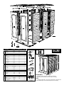
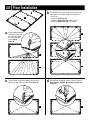
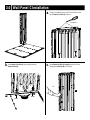
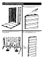
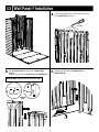
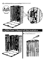
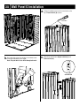
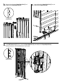
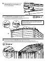
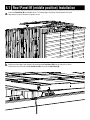
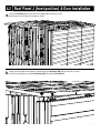
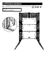
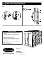
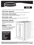
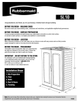
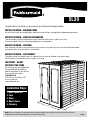
5L30
Congratulations and thank you for purchasing a Rubbermaid storage building.
BEFORE YOU BEGIN – BUILDING CODES
Be sure to check your local building codes, ordinances and restrictions, and applicable neighborhood governances.
BEFORE YOU BEGIN – SURFACE PREPARATION
To ensure proper assembly and performance your shed needs to be built on a solid, level surface.
A concrete or patio surface, or a treated-wood platform is recommended.
BEFORE YOU BEGIN – LOCATION
When choosing a location in your yard make sure you choose an area with easy access and one that provides proper
drainage for water to run away from the shed location.
BEFORE YOU BEGIN – PREASSEMBLY
Thoroughly review all assembly steps (it is important that the steps are followed in the correct order).
Review the parts list and make sure that no parts are missing.
IMPORTANT – DO NOT
RETURN TO THE STORE
For assistance with your Rubbermaid
Storage Building or for additional
product information call our toll-free
Consumer Service number:
1-888-895-2110
M–F: 8:30 a.m. to 5:00 p.m. EST
or visit us online at:
www.rubbermaid.com.
Installation Steps:
1. Site Preparation
2. Floor
3. Walls
4. Roof & Doors
5. Finishing
76 ¾"
75 ½"
55 ¼"
Note: Be sure to keep this instruction manual and your original store receipt to ensure our Consumer Service
Department can accurately and quickly assist you if necessary.
1780070
M
M
J
RB
RB
RB
G
D
C
C
F
E
E
H
L
K
B
Qx25
B
Hardware
Roof
Doors
Walls
Floor
Description
A
X
T
FFx8
Part Number Assembly Letter
Quantity
Front Floor
5L01
A
1
Repeat Floor
5L11
B
2
Repeat Left Side
5L12
C
2
Left Back
5L04
D
1
Repeat Right Side
5L13
E
2
Right Back
5L05
F
1
Front Left Side
5L02
G
1
Front Right Side
5L03
H
1
Wall Connector
5H75
Q
25
Left Door
5L06 / 5L41
L
1
Right Door
5L07 / 5L42
K
1
Door Handle
5L74
T
1
Lock Hasp
5F58
X
1
Front Roof
5L08
J
1
Repeat Roof
5L14
M
2
Roof Brace
5L36
RB
3
#14 x 3/4" Combo Pan Head Screw
AA
60*
Roof Pin
NP 5J22
FF
8
Roof Pin Assembly Tool
M3 5J22
GG
Accessory Bracket
* Extra screws are supplied
5H88
1
12
Required Tools
Two Person Assembly
Safety
Glasses
5L30
Gloves
Utility Knife
Rubber Mallet
76 ¾"
Phillips Screwdriver
Phillips Bit
Drill
1/8" Drill Bit
75 ½"
Liquid
Soap
55 ¼"
PREASSEMBLY:
• Review ALL assembly steps before beginning construction.
• Review the parts list and make sure that no parts are missing.
(2) Step Stools/
Stepladders
NOTE:
• To simplify assembly and to ensure proper engagement of all components,
apply a mild detergent to dovetail and snap fits before assembling.
CAUTIONS
CARE & USE
CAUTION: Always use gloves when using a utility knife.
CAUTION: Always use eye protection/safety glasses
during assembly.
CAUTION: When installing screws, do not overtighten.
CAUTION: Drill only through initial panel wall, unless
otherwise indicated.
• Shed can be cleaned with water and mild detergent as necessary. DO NOT USE ABRASIVE DETERGENTS,
MATERIALS OR CLEANING TOOLS.
• To maximize your shed’s performance, remove
excessive snow and/or leaf accumulation from the roof.
• In the event of severe weather, please disassemble
and store in a secure location.
1.0 Site Preparation
FLOOR PLAN:
Size the construction site to fit the entire floor.
OPTIONAL STEP:
If desired, recessed anchor locations (11 places)
can be used to anchor the shed floor to a foundation
after you have constructed one.
24 "
24 "
~3-5/8"
~3-5/8 "
~4-15/16"
24 "
75½"
~23-9/16 "
ANCHOR
LOCATIONS
~75-1/2 "
55¼"
Build a solid, level surface for the shed foundation. Consult your local
building authority for ordinances, restrictions, or permits required
before building any structure at your home.
Note: Minimum dimensions for foundations shown.
18 "
~5 "
~55-1/4 "
120.0°
24-7/8 "
Maximum opening
2.0 Floor Installation
a utility knife, cut the long side of each wall slot
b. Using
tab and then use a rubber mallet and screwdriver to
B
knock it out:
• 4 places on Front Floor (A)
• 4 places on Repeat Floor (B): middle location
• 8 places on Repeat Floor (B): rear location
B
A
a rubber mallet and
a. Using
screwdriver, punch out
B
the screw holes along
the connection edge
of both Repeat
Floors (B).
1.
B
2.
B
A
B
a rubber mallet and screwdriver, knock out the
c. Using
tabs for the door hinge, 2 places on Front Floor (A).
pilot hole through top surface of floor, 2 places on
d. Drill
Front Floor (A). CAUTION: Drill through top surface of
floor only!
A
A
2.1 Floor Installation
and align middle position Repeat Floor (B) to Front Floor (A) and install
a. Connect
Screws (AA) 9 places; keep panels aligned and even while installing screws.
HELPFUL HINT: Pilot holes may be drilled for the screws using a 1/8" drill bit.
CAUTION: Do not overtighten screws.
AA (9)
B
A
and align back position Repeat Floor (B) to middle position
b. Connect
Repeat Floor (B) and install Screws (AA) 9 places; keep panels aligned
and even while installing screws.
HELPFUL HINT: Pilot holes may be drilled for the screws using a 1/8" drill bit.
CAUTION: Do not overtighten screws.
AA (9)
B
B
A
3.0 Wall Panel C Installation
a screwdriver, punch out the screw holes on the
a. Using
top of Repeat Left Side (C) 2 places.
Screw Holes
C
C
Repeat Left Side (C) into the back position
b. Snap
Repeat Floor (B).
Repeat Left Side (C) upright to prevent it from
c. Hold
falling (until Left Back (D) is installed).
C
C
ALIGN
click
ALIGN
3.1 Wall Panel D Installation
a screwdriver, punch out the screw holes on the
a. Using
top of Left Back (D) 4 places.
Screw Holes
D
D
snaps on bottom of Left Back (D) into
b. Connect Left Back (D) into dovetails of Repeat Left Side (C). c. Engage
Repeat Floor (B).
HELPFUL HINT: Lubricate dovetails with liquid soap.
D
D
D
C
3-3_E
DETAIL
SCALE 1/1
OVERHEAD VIEW
C3-1_B
1
2
1
click
DETAIL
SCALE 1/1
3-3_B
DETAIL
SCALE 1/1
2
B
ALIGN
ALIGN
3.2 Wall Panel E Installation
a screwdriver, punch out the screw holes on the
a. Using
top of Repeat Right Side (E) 2 places.
Screw Holes
E
Repeat Right Side (E) into the back position of
b. Snap
Repeat Floor (B).
E
Repeat Right Side (E) upright to prevent it from
c. Hold
falling (until Right Back (F) is installed).
E
ALIGN
click
ALIGN
click
_E
3.3 Wall Panel F Installation
a screwdriver, punch out the screw holes on the
a. Using
top of Right Back (F) 4 places.
Screw Holes
F
F
Right Back (F) onto dovetails of Repeat Right
b. Connect
Side (E).
Align the lap joint between Left Back (D) and Right Back (F).
snaps on bottom of Right Back (F) into
c. Engage
Repeat Floor (B).
HELPFUL HINT: Lubricate dovetails with liquid soap.
F
F
D
1
F
Align Lap Joints
3-3_E
DETAIL
SCALE 1/1
F
E
2
OVERHEAD
VIEWS
1
3-3_B
3-3_B
DETAIL
SCALE 1/1
DETAIL
SCALE 1/1
E
click
2
ALIGN
Wall Connector (Q) 5 places, connecting Left Back and Right Back Panels (D and F).
d. Install
Position connectors in slots and slide down to snap in place.
D
F
Install Wall
Connectors
1
D
1
F
OVERHEAD VIEW
Q
2
click
3.4 Wall Panel C (Repeat Left Side) Installation
a screwdriver, punch out the screw holes on the
a. Using
top of Repeat Left Side (C) 2 places.
C
C
3-1_B
3-3_B
DETAIL
SCALE 1/1
the lap joint between back position Repeat Left Side
b. Align
(C) and middle position Repeat Left Side (C).
middle position Repeat Left Side (C) into the
c. Snap
middle position Repeat Floor (B).
C
C
C
1
C
OVERHEAD VIEW
2
C
1
3-4_B AND 3-5_B
DETAIL
SCALE 1/1
3-6_B AND 3-7_B
DETAIL
SCALE 1/1
2
click
ALIGN
ALIGN
Wall Connector (Q) 5 places, connecting 2 Repeat Left Sides (C and C).
d. Install
Position connectors in slots and slide down to snap in place.
C
C
1
OVERHEAD VIEW
1
Q
2
click
C
C
DETAIL
SCALE 1/1
3.5 Wall Panel G Installation
a screwdriver, punch out the screw holes on the
a. Using
top of Front Left Side (G) 2 places.
Screw Holes
G
G
3-1_B
DETAIL
SCALE 1/1
a pilot hole (using 1/8" drill bit) in front lower corner
b. Drill
at location indicated by screw target.
the lap joint between Repeat Left Side (C) and
c. Align
Front Left Side (G).
Note: This pilot hole is to be drilled through both walls.
C
G
G
G
OVERHEAD VIEW
C
1
3-4_B AND 3-5_B
DETAIL
SCALE 1/1
2
d. Snap Front Left Side (G) into Front Floor (A).
Wall Connector (Q) 5 places, connecting Repeat Left
e. Install
Side (C) and Front Left Side (G).
Position connectors in slots and slide down to snap in place.
G
C
1
G
2
OVERHEAD VIEW
G
1
click
Q
1
2
ALIGN
ALIGN
click
3.6 Wall Panel E (Repeat Right Side) Installation
a screwdriver, punch out the screw holes on the
a. Using
top of the middle position Repeat Right Side (E)
2 places.
Screw Holes
E
E
3-3_B
DETAIL
SCALE 1/1
the lap joint between Repeat Right Side (E) and
b. Align
middle position Repeat Right Side (E).
middle position Repeat Right Side (E) into the
c. Snap
middle position Repeat Floor (B).
E
E
E
E
OVERHEAD VIEW
1
E
3-6_B AND 3-7_B
DETAIL
SCALE 1/1
2
click
ALIGN
ALIGN
Wall Connector (Q) 5 places, connecting Repeat Right Side (E) and middle position Repeat Right Side (E).
d. Install
Position connectors in slots and slide down to snap in place.
E
E
1
1
OVERHEAD VIEW
E
Q
2
click
3.7 Wall Panel H Installation
a screwdriver, punch out the screw holes on the
a. Using
top of the middle position Front Right Side (H) 2 places.
Screw Holes
H
H
3-3_E
DETAIL
SCALE 1/1
3-1_B
3-3_B
DETAIL
SCALE 1/1
DETAIL
SCALE 1/1
a pilot hole (using 1/8" drill bit) in front lower corner
b. Drill
at location indicated by screw target.
Note: This pilot hole is to be drilled through both walls.
the lap joint between Front Right Side (H) and
c. Align
middle position Repeat Right Side (E).
E
H
H
H
OVERHEAD VIEW
E
3-4_B AND 3-5_B
DETAIL
SCALE 1/1
3-6_B AND 3-7_B
DETAIL
SCALE 1/1
1
2
d. Snap Front Right Side (H) into Front Floor (A).
Wall Connector (Q) 5 places, connecting middle
e. Install
section Repeat Right Side (E) and Front Right Side (H).
H
E
H
OVERHEAD VIEW
E
H
click
1
Q
2
ALIGN
ALIGN
click
4.0 Roof Panel M (back position) Installation
one Repeat Roof (M) onto back section. The overlap edge of roof points toward the back of the shed.
a. Install
Align tongues on top of back wall to the outside of the roof panel overlap.
Align tongues on top of side walls into grooves in roof.
M
RB
1
raise front edge of roof enough to allow positioning
b. Slightly
of Roof Brace (RB) onto the side walls as shown.
Lower the roof onto the walls and align Roof Brace (RB)
into pocket in Repeat Roof (M).
M
RB
Repeat Roof (M) is positioned against the back wall tongues.
c. Ensure
From outside the shed, install one Screw (AA) at each corner.
AA (8)
Hold the edge of the roof down firmly at the corners while installing each screw.
Install remaining screws into remaining locations of back walls.
1.
2.
Helpful Hint: Installation is easier using a magnetic bit or starting
screws with a manual screwdriver to get seated. Pilot holes also
may be drilled using 1/8" bit.
M
3.
inside the shed, install four Screws (AA) into the roof at each side wall location.
d. From
Note: The screws also have to go through the Roof Brace (RB) at each end to properly secure the roof!
A second person on the outside of the shed should hold down the edge of the roof firmly at each screw location.
AA (4)
M
RB
4.1 Roof Panel M (middle position) Installation
one Repeat Roof (M) onto middle section. The overlap edge of roof points toward the back of the shed.
a. Install
Align tongues on top of side walls into grooves in roof.
M
RB
raise front edge of roof enough to allow positioning of Roof Brace (RB) onto the side walls as shown.
b. Slightly
Lower the roof onto the walls and align Roof Brace (RB) into pocket in Repeat Roof (M).
RB
M
sure middle location Repeat Roof (M) is positioned tightly against the back Repeat Roof (M) section.
c. Make
Install Roof Pins (FF) in four places. If necessary, use Roof Pin Assembly Tool (GG) to pull the roof down.
1. Insert pin in slot.
2. Push all the way through.
3. Rotate head flush with roof.
click
FF
GG
Install Roof Pins four places.
inside the shed, install four Screws (AA) into the roof at each side wall location.
d. From
Note: The screws also have to go through the Roof Brace (RB) at each end to properly secure the roof!
A second person on the outside of the shed should hold down the edge of the roof firmly at each screw location.
AA (4)
M
RB
4.2 Roof Panel J (front position) & Door Installation
one Front Roof (J) onto front section: roof gable edge toward front of shed.
a. Install
Align tongues on top of side walls into grooves in roof.
J
RB
raise front edge of roof enough to allow positioning of Roof Brace (RB) onto the side walls as shown.
b. Slightly
Lower the roof onto the walls and align Roof Brace (RB) into pocket in Front Roof (J).
RB
J
sure Front Roof (J) is positioned tightly against the middle Repeat Roof (M) section.
c. Make
Install Roof Pins (FF) in four places. If necessary, use Roof Pin Assembly Tool (GG) to pull the roof down.
1. Insert pin in slot.
2. Push all the way through.
3. Rotate head flush with roof.
click
FF
GG
Install Roof Pins four places.
Left Door (L) and Right Door (K) into hinge openings
inside the shed, install four Screws (AA) into the roof
d. Install
e. From
of Front Floor (A) and hinge sockets in Front Roof (J).
at each side wall location.
Note: Only raise front edge of roof enough to install the
door hinge pins.
Note: The screws also have to go through the Roof Brace
(RB) at each end to properly secure the roof!
A second person on the outside of the shed should hold
down the edge of the roof firmly at each screw location.
AA (4)
J
J
L
K
J
L
A
K
A
RB
5.0 Finishing Installation
a. Install Screws (AA) into 10 locations shown at bottom of wall panels to secure walls to floor.
HELPFUL HINT: Pilot holes may be drilled for the screws.
CAUTION: Do not overtighten screws.
AA (10)
5.1 Door Finishing Installation
Door Handle (T) onto Left Door (L) using four
a. Install Lock Hasp (X) into opening on Right Door (K).
b. Install
Screws (AA).
AA (4)
T
X
K
click
L
MAINTENANCE & SAFETY
• Periodically check shed to assure it remains stable and the site remains level.
• In areas of high winds it is recommended to anchor shed to platform or ground by holes in floor at designated location and secure with the proper fasteners (not included).
• Wash shed with garden hose or a mild detergent solution. Using an abrasive cleaner could damage your shed.
• Hot items such as recently used grills or fire pits should not be stored in the building.
• Heavy items should not be leaned against the walls, as this may cause distortion.
• Keep doors closed when not in use to prevent wind damage.
• Do not climb onto roof.
• Shed is not designed for habitation.
76 ¾"
75 ½"
55 ¼"
Printed in U.S.A.
2009 Rubbermaid Incorporated,
Huntersville, NC U.S.A. 28078-1801
Customer Service
Toll Free: 1-888-895-2110
M-F 8:30AM to 5PM EST
or visit us at www.rubbermaid.com