1
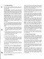
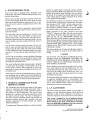
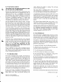
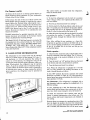
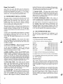
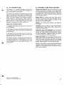
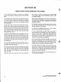
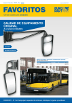
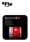
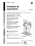
26 FT.
MOTOR HOME
AV I O . INTERIOR
Operation and Service Manual
Keep this book with your Motor Home at all times
AVION COACH CORPORATION
1300 E . Empire Avenue, Benton Harbor, Michigan 49022
26 FT . AVION INTERIOR
OPERATION AND SERVICE MANUAL
TABLE OF CONTENTS
Section
Page
I
General Operating Instructions
3
II
Operation - Care - Maintenance
4
III
Protection From Freezing Weather 14
IV
Trouble Shooting
16
V
Warranty Information
18
VI
Diagrams and Illustrations
19
GMC 26 FT . AVION INTERIOR
OPERATION AND SERVICE MANUAL
I
j
,
low
Avion Coach Corporation warrants the basic construction for any
component equipment that is installed by the factory, except batteries, against defective material or workmanship for a period of
twelve months from date of purchase .
We agree to repair or replace defective parts at no charge for
parts or labor .
All repairs to be made under the terms of this warranty shall be
authorized in advance by Avion Service Corporation, 1576 East
Empire Avenue, Benton Harbor, Michigan 49022 .
Transportation to and from the authorized service center or
dealer shall be the responsibility of the owner .
j
This warranty is in lieu of all other warranties, expressed or implied, and excludes conditions from normal wear, accident,
abuse, exposure, overload or inadequate routine maintenance
as suggested in the owner's manual .
J
SECTION I
GENERAL OPERATING INSTRUCTIONS
The following steps are suggested as a check list before
starting on a trip .
1 . See that all clothing, dishes, supplies, and equipment
are properly stored . Avoid traveling with opened food or
liquid containers . Secure the refrigerator door with the
travel latch . Close all cabinet doors and drawers . Avoid
storing heavy objects in overhead cabinets .
2 . Disconnect the 120/240 v . power cord and coil it in
the storage compartment and lock the door .
3 . Fill the water storage tank and lock the fill spout door .
4 . Check the holding tank drain to be sure it is secured
in the travel position, and lock the valve handle in the
closed position .
5. Inspect the area around the vehicle to be sure nothing
has been placed under it . Check for obstructions that
might be in the path of the vehicle .
6 . Turn off appliance gas valves and the main L .P . tank
valve . Close the bifold top on the galley range .
7 . Lock the entrance door . Adjust and secure the swivel
seats in the forward-facing position before putting vehicle
in motion . The permanent beds are not designed for
seating while the vehicle is in motion .
Front
Rear
Total
Curb
Weight
3820
5490
9310
Maximum
Cargo
Weight
420
2010
2430
Gross
Axle
Weight
4240
7500
11,740-GVW
Curb Weight is the weight of the vehicle with fuel and
coolant, but without the weight of cargo, passengers, driver, or optional equipment .
Cargo includes driver, passengers, water, luggage, and
sup l e .
Gross Axle Weight (GAWR) is the maximum load that
may safely be applied to the axle, including cargo and
options . This weight can be checked on any scale which
will accommodate both front wheels, or all four rear
wheels at the same time . Be sure driver and passengers
are seated in the vehicle when the weight is checked .
d"_
h e
- .a
t GVW ) is the maximum permissible weight of the vehicle, complete with cargo . This
weight can be checked on any scale that will accommodate all six wheels at one time . Be sure driver and passengers are seated in the vehicle when the weight is
checked .
TIRE INFLATION
STORAGE SPACE
Storage space is provided under the dinette seats, the
love seat, and the right bed . Space is also available under
both vanity cabinets as well as in the closet, and the three
overhead cabinets . A special ski locker is built under the
raised floor area . This space is accessible from an exterior door, located on the right side of the vehicle, and
through the opening under the love seat .
Tire inflation pressures are listed on a placard on the
glove compartment door . It is important that these recommended pressures be maintained . Check pressure before starting each trip . Additional information regarding
your vehicle tires may be found in the GMC Transmode
Vehicle Operating Manual supplied with this motor
home .
DINETTE CONVERSION
EMERGENCY EQUIPMENT
Emergency equipment is located under the rear-facing
dinette seat. This equipment includes the jack, jack handle, lug wrench, chain and wood block . See the GMC
Transmode Vehicle Operating Manual for instructions
relating to the use of this equipment .
LOADING
Loading should be planned to distribute the weight as
equally as p ossible . D O NOT EXCEED GROSS AXLE
OR GROSS VEHICLE RATINGS LISTED BELOW .
The following information is provided to assist in proper
loading .
GMC 26 FT . AVION INTERIOR
OPERATION AND SERVICE MANUAL
To make the dinette into a 42" double bed, use the following steps .
1 . Remove the two seat cushions and fold the two keeper
strips down flat.
2. Unlock the dinette table from the wall by releasing
the latch on the underside . Support the table, fold the leg
and lift the table from the wall bracket .
3 . Place the table on the edge of the two dinette seats, in
the notches provided .
4 . Place all four cushions on the table and seat boards to
obtain the 42" x 72" sleeping surface .
When converting the bed back to a dinette, be sure to
support the table in a horizontal position until the leg is
extended .
SECTION II
,M)
OPERATION - CARE - MAINTENANCE
Item
Description
Page
1.
Electrical Systems .
5
2.
Water System
7
3.
Water Closet
7
4. Waste Holding Tank
8
5.
Thermasan Waste Disposal System 8
6.
L.P. Gas System
8
7.
Water Heater 9
V4~
8.
Gas Furnace
9.
Gas - Electric Refrigerator
10
10 .
Range and Oven
11
11 .
Range Vent
11
12.
Instrument Signal Center
12
13.
Air Conditioner
12
14.
TV Antenna
13
15.
Care and Cleaning
13
.
9
'j
4
GMC 26 FT . AVION INTERIOR
OPERATION AND SERVICE MANUAL
SECTION II
OPERATION - CARE - MAINTENANCE
1. ELECTRICAL SYSTEMS
All Avion Interior Motor Homes are equipped with two
sources of electrical energy . If it is equipped with a generator, three sources of energy are available .
120-VOLT SYSTEM
A 25-foot power cord is provided to permit the use of an
external power source . The cord is stored in a compartment on the left side of the coach, just above the wheel
housing. The door is secured with a keyed lock . The cord
is equipped with a 4-wire plug to provide two 120-volt
circuits when connected to a conventional 240-volt, 60cycle receptacle . D O NOT CONNECT TO AN OUTSIDE RECEPTACLE THAT DOES NOT MATCH
THE POWER CORD PLUG .
The distribution panel is located in the bath vanity cabinet . It provides a 40-amp main disconnect and individual circuit breakers for four separate circuits .
The water heater, power converter, wall outlets, and optional air conditioners operate directly from the 120-volt
circuits . These circuits are shown in Section VI in the
back of this manual .
12-VOLT SYSTEM
The 12-volt electrical system is divided into two parts .
The engine or chassis system, and the interior or household system . These circuits are shown in Section VI in
the back of this manual .
fans in the living area . They also provide the energy for
starting the optional generator engine . Separate fuses are
used to protect each battery circuit . The two rear batteries may be isolated by removing the 40-amp fuse from
the in-line holder in the battery box .
Battery Maintenance - Check the batteries periodically
to maintain proper electrolyte (water) level . When the
electrolyte level is low, add distilled or filtered water to
obtain the correct level . Batteries may be permanently
damaged by traveling and/or charging with the plates not
fully covered .
There are three ways in which the three house batteries
may be charged :
(a) by the converter
(b) by the optional generator
(c) by the engine alternator
The two batteries in the rear compartment are supplied
by AVION . They are TITAN 85 A .H . Recreational Vehicle Batteries, carrying a 24-month service adjustment
policy and a 90-day warranty against defects in workmanship or material.
For information as to the nearest TITAN Battery dealer
or distributor, consult the yellow pages, or call collect
GENERAL BATTERY CORP ., AC 215 929-0771 .
The Titan Battery Stock No . is RVS-24-6 . A copy of the
battery Owner's Guide is included in each warranty
package .
Power Converter - The combination converter-charger
Chassis Batteries - Two batteries are located behind the provides 12-volt direct current power whenever the power cord is plugged into a standard 120/240 volt, 60-cycle
right front engine access door . The forward battery pro.
It
is
isoA .C . source, and when plugged into the cord box receptvides energy for the engine and chassis circuits
acle with the generator running . The converter has a dual
lated from the interior system by a diode assembly to
output. One circuit provides energy to charge the batterprevent accidental discharge of all batteries in the 12-volt
ies . The second circuit provides the energy to power the
circuits .
lights, fans, and water pump .
The second battery in the front compartment is part of
The battery charger circuit senses the state of the battery
the interior system . It feeds a fuse panel located in the
charge and will automatically charge and shut off as rebath vanity storage compartment . It can be isolated from
quired .
the system by removing the panel fuse marked AUX .
.
See
Illustration
on
page
6
.
BATTERY
The converter has a built-in relay that automatically
Rear Interior Batteries - Two additional batteries are
located in a sealed compartment under the rear end of
the left bed . Access is through the rear section of the removable bed board . These are also connected to the fuse
panel, providing 12-volt energy for all of the lights and
GMC 26 FT. AVION INTERIOR
OPERATION AND SERVICE MANUAL
switches the 12-volt system to the battery circuit when
the power cord is disconnected from the generator, or
from a 240-volt source .
continued on next page
5
Electrical Systems (cont'd .)
The converter is protected by a built-in circuit breaker .
If a short, or overload is occurring, a 7 to 10 second
clicking sound will be heard as the automatic circuit
breaker opens and closes . The load can be reduced by
turning off a light or fan .
The converter is located under the galley cabinet shelf.
It may be disconnected by removing the plug from the
wall outlet adjacent to the unit . Do not pile things against
it, so air cannot circulate around it .
The power converter is warranted for a period of one
year . A copy of the warranty form and registration form
are enclosed in the warranty package .
Parts and warranty information may be obtained from
Progressive Dynamics, Inc ., 604 S . Kalamazoo Ave .,
Marshall, Michigan 49068 . The telephone number is
AC 616 781-4241 .
Fuse Blocks - Two fuse blocks are provided to protect
the 12-volt system . They are located under the bath vanity top, behind the left cabinet door . The accompanying
diagram shows the various fuses and their sizes . The battery-to-converter circuit is protected by two 20-amp fuses
in parallel . Both fuses must be in place at all times so
that the load is divided between them . Two extra clips are
provided to store spare fuses .
12-Volt Outlets - Two 12-volt outlets are provided for
convenient use of radios, T .V . sets, and appliances . One
is located at the galley countertop, and the other is beside
the bedroom vanity cabinet . These outlets are combined
with T .V . antenna jacks and wired for connection to the
optional T .V . antenna .
NT ERIOR
USE BLOCKS
IS
FURNACE B R . LIGHTS
0
25 A .
WATER
Q
IS
LEFT LIGHTS
PUMP
CEILING LIGHTS
REFRIGERATOR A R . LIGHTS
G A.
20 A
F-
30 A,
AUK . BATTERY
NTFRIOR
VOLT OUTLETS
BATTERY
PAR
BATTERY
6
Bulb Replacement - The various cabinet cornice board,
and ceiling light fixtures use an automotive No . 1141,
12-volt bulb .
1
The power range vent uses an automotive No . 1156, or a
No . 1141 bulb . The vent face is held in place by the two
switch nuts . These can be removed to facilitate bulb replacement and cleaning of the vent filter .
The oven light in the range uses a 12-volt, 15-watt standand-base bulb .
Power Vents - The ceiling fans and the bath exhaust fan
operate on 12-volts . Be sure to raise these vents before
turning on the fan motors, and be sure to close them before traveling .
ONAN GENERATOR - OPTIONAL
The Onan 6000-watt, 110-volt generator provides a third
source of electrical energy . The generator is located in a
compartment behind the rear wheels on the left side of
the vehicle . It is mounted on slides, so that it may be
pulled out for ease of access . To open, depress the two
latch buttons to release the latches, then turn the release
handle and pull .
The generator uses fuel from the two CHASSIS engine
gasoline tanks . To prevent running both tanks dry, be
sure the fuel switch on the driver's instrument panel is in
the `FUEL MAIN' position .
A circuit breaker is mounted on the generator for protection from overload . Start-and-Stop controls are
mounted on the generator and also wired from the remote
switch on the Instrument Signal Center . The control
board on the generator is protected by a 5-amp fuse, located under the control cover .
1J
The generator electrical output is connected to a 240 volt
receptacle installed inside the power cord box . Inserting
the power cord plug into this receptacle will connect the
generator output to the 120/240 volt distribution panel .
If this connection is made each time the power cord is
stowed in the compartment, the generator may be started
remotely and used at any time without need to leave the
motor home.
Regularly scheduled maintenance is important . The generator oil level should be checked after each 8 hours of
operation . Other periodic maintenance work is required
after 50 hours, 100 hours, etc . Consult the Operation
Manual provided with each unit for detailed operating
and maintenance instructions . A parts list is also included .
The ONAN R.V . Power Plant is warranted by the manufacturer for a period of one year . Be sure to fill out the
Warranty Registration Card and mail it promptly . For
warranty work, information, or parts, consult the Parts
and Service Center list provided with each unit .
GMC 26 FT. AVION INTERIOR
OPERATION AND SERVICE MANUAL
1
2. WATER SYSTEM
~Sr
The motor home is equipped to provide water service
from a city water system or from the self-contained water storage tank .
City Water Supply - Connections to a city water supply
are made through a water hose connected from the city
supply to the water inlet fitting on the coach . This fitting
is located inside the cord storage compartment on the
left side of the vehicle . A pressure regulator in the system
prevents excessive city pressures from being introduced .
Water Storage Tank - The water storage tank is located
beneath the right bed. It has a capacity of 36 gallons .
A cold air return vent is built into the cabinet . This vent
permits the circulation of warm air to prevent freezing
during cold weather operation . A locking fill spout is
located at the rear of the coach, near the right side . A
diagram of the water system is included in Section VI of
this manual .
To assure complete sanitation of your potable water system, it is recommended that the following procedures be
followed on a new system, one that has not been used for
a period of time, or one that may have become contaminated :
1 . Prepare a chlorine solution using one gallonof water
and 1/4 cup of Chlorox or Purex household bleach
(5% sodium hypochlorite solution) . Pour one gallon
of solution into tank for each 15 gallons of tank capacity .
2 . Complete filling of tank with fresh water . Open each
faucet and drain cock until all air has been released
from the pipes and entire system is filled .
3 . Allow to stand for three hours .
4 . Drain and flush with potable fresh water .
5 . To remove any excessive chlorine taste or odor which
might remain, prepare a solution of one quart vinegar
to five gallons water and allow this solution to agitate
in tank for several days by vehicle motion .
6 . Drain tank and again flush with potable water .
The tank may be drained by opening any faucet with the
pump turned on, or by opening the drain valve at the aft
end of the tank .
A remote monitor switch is provided to indicate the water level . See Item No . 12 for additional information .
Water Pump - A demand pump is provided to supply
water pressure whenever a valve is opened in the plumbing system . A switch is provided to turn the pump off
whenever the vehicle is left unattended, or when connected to a city water system . The switch is located on
the Instrument Signal Center .
The pump should also be turned off when traveling . The
GMC 26 FT . AVION INTERIOR
OPERATION AND SERVICE MANUAL
surge of water, which can occur during vehicle starting
and stopping, may cause the pump to turn on . With no
open valve to allow the pump to cycle, it may run continuously and eventually be damaged .
The water pump is located at the aft end of the water
tank . It has a built-in check valve to prevent water from
backing up into the storage tank when the system is connected to a city water source .
The Model 6950-J pump is warranted by the manufacturer for a period of one year . Warranty service and parts
may be obtained from : ITT, Jabsco Products, 501 W .
Liberty Street, Springfield, Ohio 45501 . The telephone
number is AC 513 325-8701 .
Water Line Filter - A filter is located in the water line
between the tank and the pump . Inspect this filter periodically to be sure that an accumulation of foreign matter does not impair the water flow . The filter may be
cleaned by removing it and rinsing or back-flushing .
Shower - The shower stall is constructed of molded fiberglass . Clean with a liquid detergent, then rinse . Do
not use abrasive cleaners as they will dull the surface .
The shower is equipped with an adjustable shower head
and flexible hose . The head may be removed from the
bracket for maximum efficiency . The built-in push button
on the shower head is designed for volume control (water
saver) and is not intended as a shut-off valve . A slight
trickle in the closed position is normal .
Note : Be sure to remove the shower pan drain plug before turning on the water . Keep it in the drain, except
when using shower .
3 . WATER CLOSET (Toilet)
Your motor home is equipped with a Thetford Aqua
Magic pedal-operated water closet . To flush : step on the
large pedal until the water swirls, then release the pedal .
To add water to the bowl : step on the small pedal until
water reaches the desired level, then release .
The Aqua Magic Toilet may be cleaned with any high
grade, non-abrasive cleaner. Do not clean with a highly
concentrated, or high acid content household cleaner .
These may damage the rubber seals .
The Aqua Magic Toilet does not require routine maintenance . If the bowl sealing blade should fail to operate
freely after extended use, apply a light film of silicone
spray to the blade .
The Thetford Aqua Magic Toilet is warranted by the
manufacturer for a period of one year according to the
terms and conditions of the warranty statement . Warranty service and parts may be obtained from Thetford
Corporation, 3001 S . State St ., Ann Arbor, Michigan
48106, P .O . Box 1285 . Their telephone number is AC
313 769-6000 .
7
4. WASTE HOLDING TANK
Your motor home is equipped with a 40-gallon waste
holding tank . This tank is installed beneath the floor near
the rear of the vehicle .
Waste water from the two lavatories and the shower flow
into the tank through drain lines . Waste from the stool
goes into the tank through an opening in the top . A diagram of the drain system is included in Section VI of this
manual .
A remote monitor switch is provided to indicate liquid
level in the holding tank . Refer to Item 12 for more detailed information .
The tank drain valve and connection is located at the
rear of the vehicle . The valve handle is locked in the
sevclosed position with a red plastic nut . Turn this .nutAlways
eral times counterclockwise to release the handle
lock the handle to prevent accidental discharge when not
in use .
It is not wise to keep the tank valve open . The low volume of water used with each flush may not be adequate
to flood away all of the solids . The result can be a buildup that is difficult to remove . Keep the dump valve closed,
run about 1" of water into the tank, and dump every few
days .
A drain cap is provided to prevent accidental dumping
of accumulated waste . The cap should be in place while
traveling, but it must be removed and the sewer hose connected before opening the valve .
The waste holding tank drain extension pipe is designed
to swing down for draining . A cable supports it in the
normal `drain' position . When preparing to travel, the
pipe should be capped and secured tight to the frame with
the rubber strap .
When using the coach in freezing temperatures, a permanent antifreeze may be added to the waste holding tank .
Use an ethylene glycol type antifreeze . Follow the directions on the container to obtain the desired protection .
5. OPTIONAL THERMASAN WASTE
DISPOSAL SYSTEM
The Thermasan unit uses the heat energy of the engine
exhaust to disintegrate the holding tank wastes . This is
done after a breaking-down action is initially created in
the contents of the holding tank . The waste is next
pumped into a sanijector which screens and sprays it into
the engine's exhaust system . The waste is destroyed to
the extent that all remaining gaseous by-products are
rendered invisible, bacteria free, harmless, and meet
emission requirements of Public Health and Federal
Emission Standards .
To operate your Thermasan System, two factors must be
present: an engine under work load, and the vehicle's
speed exceeding 35 MPH . Operation of the control panel,
without these factors being available, will not activate
the system . If the engine load should drop below limits,
or the vehicle speed is reduced, operation of the system
will be temporarily interrupted .
The Thermasan controls are located to the left of the
steering column in the driver's compartment . The panel
face contains an "ON"/"OFF" switch, a pull to test feature, and three indicator lights . The "ON"/"OFF" switch
also contains a rheostat control to be used if dimming
the indicator lights is desired during night operation .
1
01
When switched to the "ON" position, the green
"READY" indicator will light . This tells you the system
is operational . When the speed and engine load requirements are met, the red "REACTION" indicator will
light, which tells you the system is operating . When the
white indicator lights, the system has destroyed all waste
above the holding tank evacuation probe and the system
should be turned "OFF" . When the "ON"/"OFF" switch
is pulled out, the "REACTION" indicator light will blink
if the pump is running .
The system operates on 12-volts and will destroy approximately one gallon of waste for every fifteen miles of
driving .
CAUTION
DO NOT PUT ANY HIGHLY COMBUSTIBLE MATERIALS SUCH AS KEROSENE, ALCOHOL, OR
GASOLINE IN YOUR HOLDING TANK SINCE IT
COULD CREATE AN EXPLOSION HAZARD IN
THE VEHICLE EXHAUST .
Ij
Do not winterize your motor home with fuel oil or kerosene, which might get into the holding tank . We also
recommend that facial-type tissue, paper towels, e tc . be
kept from the holding tank because they have `wet
strength' and they will not properly dissolve for passage
through the waste pump .
Occasional draining and flushing of your holding tank at
an approved dumping station is recommended . This
should be done periodically to remove any foreign particles or other insoluble matter. The use of Aqua Kem
holding tank chemical is recommended .
6. L.P. GAS SYSTEM
The motor home gas system consists of a gas tank, a
regulator, the gas distribution piping, and the following
appliances : range & oven, refrigerator, and furnace . A
schematic diagram is shown in Section VI of this manual .
This system is designed for use of liquified petroleum
(LP) gas only . Do not connect natural gas to this system .
Before turning on gas, make certain all gas connections
have been made tight, all appliance valves are turned off,
and any unconnected outlets are capped.
1'~
GMC 26 FT . AVION INTERIOR
OPERATION AND SERVICE MANUAL
8
L.P. Gas System (cont'd .)
After turning on gas, test piping and appliances for leakage with soapy water, and light all pilots .
The gas tank is located in an exterior compartment at the
right rear side of the coach . It is equipped with a valve to
control the flow of gas, a combination visual/remote
level indicator, and a pressure regulator to control the
pressure in the piping system . The regulator is preset at
the factory to maintain a pressure of 11 inches water
column, or approximately 6 1/2 ounces per square inch .
All appliances are adjusted to operate at this pressure .
DO NOT REMOVE THE TANK TO FILL IT . Drive
the motor home to an L .P . gas dealer to have it filled .
Turn off the tank valve before entering the fill depot .
The valve is located on the side of the tank . Except when
operating the gas system, it should be closed at all times .
All gas line fittings, except those at the individual appliances, are located outside the coach . Several connections
will be found under the coach, where the main gas line
branches off to supply the individual appliances . These
gas lines and fittings should be inspected and tested periodically for possible damage and leaks . Brush or spray a
soap suds solution over all fittings and any damaged areas
in the line . The bubbles will grow in size to indicate the
presence of a leak .
If the odor of gas is detected inside the coach, extinguish
all flames and test for leaks . If the leak cannot be detected, turn off the valve on the gas bottle and see your
dealer's service department, or a competent gas appliance service m an . D O NOT CONTINUE TO USE
YOUR GAS SYSTEM UNTIL THE LEAK IS LOCATED AND ELIMINATED .
The gas appliances in your coach are designed and adjusted to use L .P . gas . Propane gas is the most common
type . Butane may be used but will not vaporize, or turn
to gas, at temperatures below 31 ° F .
7. WATER HEATER
Your coach is equipped with a 6-gallon, 110-volt electric
water heater . It is located under the forward end of the
left bed . A separate circuit breaker is provided in the
distribution panel to protect this circuit . In addition, an
"ON"/"OFF" switch is located on the front face of the
water heater . Be sure that water is in the heater tank before turning it on . Open the hot water faucets until all air
is eliminated before turning on the switch and breaker .
water whenever the engine is running . This will help
conserve electrical energy .
The water heater is equipped with a drain valve and
tube extending down through the floor . Location is shown
on a pictorial diagram in Section III of this manual .
A combination temperature/pressure relief valve is also
located on the front of the heater jacket, and is drained
through the floor . It protects the heater tank and water
system against excessive temperatures or pressures . It is
normal for water to drip from this drain. while being
heated.
The Atwood Bowen Model EH6 water heater is warranted for a period of two years according to the terms
of the statement included in the Warranty package .
Warranty service and parts may be obtained from any of
the authorized service stations on the list, or by contacting ATWOOD MOBILE PRODUCTS DIVISION,
1400 Eddy Avenue, Rockford, Illinois 61101 . Their
telephone number is AC 815 877-5771 .
8 . GAS FURNACE
Your motor home is equipped with a Sol-Aire gas-fired,
forced air furnace . The furnace blower operates on 12volt electricity . It has an automatic spark ignition unit .
There is no pilot light, and no manual lighting is required .
The furnace is located under the range in the sink cabinet . Hot air is distributed to different areas of the coach
through ducts . These are shown in a diagram located in
Section VI of this manual .
To operate the furnace, use the following procedure :
1 . Open the tank valve and the line valve . The line valve
is located at the front of the furnace .
2 . Turn the thermostat to the lowest setting .
3 . Press the manual reset button on the furnace .
4 . Turn the thermostat to a temperature setting above
room temperature . The furnace should start .
5 . Set the thermostat to the desired temperature and it
will cycle the furnace on and off as the temperature satisfies the thermostat .
6 . To turn the furnace off, set the control to the lowest,
or "OFF", setting . The burner will shut off immediately
and the blower will stop as soon as the furnace cools
slightly . Turn the gas valve off when not in use .
A thermal protective device is located inside the electrical box on the water heater front . It may be reset by removing the cover and pushing the reset button .
Temperature adjustment can be made by rotating the
louvres on the hot air registers to direct more warm air
in the desired areas .
If your water heater is equipped with the optional Engine Preheat, it will have two hoses connecting it to the
engine heater lines . These will provide automatic hot
The furnace is protected by safety devices which will stop
continued on next page
GMC 26 FT . AVION INTERIOR
OPERATION AND SERVICE MANUAL
9
Gas Furnace (cont'd.)
The control knobs are located inside the refrigerator,
under the bottom shelf .
the furnace in the event of : (1) burner ignition failure (2)
burner flameout during operation (3) poor combustion
(4) lack of fuel (5) low voltage .
Gas operation -
If the furnace has shut off for any of these reasons, the
Reset Button must be pressed to reactivate the control
circuit . Before the Thermal Relay will properly reset, a
wait of at least 5 minutes is required after the furnace has
stopped . The D .C . portion of the control circuit is also
fused at the furnace and at the 12-volt fuse panel . See
furnace illustration in Section VI for identification and
location of controls .
Detailed instructions for periodic inspection and maintenance check-out are provided in the furnace manual
which is included in the warranty package .
The Model 30-I-4P-12 Sol-Aire furnace is warranted by
the manufacturer for a period of one year . For warranty
information and parts, contact TRI-MEN MANUFACTURING, INC ., SOL-AIRE DIV ., 1359 W . Jackson
Street, Painesville, Ohio 44077 . Their telephone number
is AC 216 352-6158 .
9 . GAS-ELECTRIC REFRIGERATOR
The refrigerator in your motor home may be operated
from any of three sources of heat energy : L .P . gas, 12volt electricity, or 110-volt electricity . By setting the
control to 12-volt electric, the refrigerator may be operated with power from the engine alternator while traveling . When parked, the refrigerator may be operated
from L .P . gas if no outside source of electrical energy is
available . When the electrical power cord is connected to
an external power source, or when running the optional
power generator, the refrigerator may be operated on
110-volts .
I
1
1 . To start the refrigerator turn the knob A to position
"Gas" . The gas valve is now opened and the electric circuits are broken .
2. Turn the gas thermostat knob C to setting 4 .
3. Pull the knob D of the flame failure safety device and
after 15 seconds press the button E of the piezo lighter .
The pressing may have to be repeated . Through the reflector F it can be observed that the burner is lit.
4. After the burner has been lit keep the knob D in pulled
out position for another 15 seconds . Then release the
knob and check through the reflector that the burner
stays lit .
Note : After refilling the gas container or a long shutoff period the gas lines are likely to be filled with air . In
such a case the lighting procedure has to be repeated until the air is pushed out of the lines and the gas has
reached the burner .
Electric operation 1 . Check that the attachment plug of the flexible cord is
correctly connected to the main supply . The 12 Volt connection is made at the marked terminals at the rear of
the refrigerator .
2 . Turn the knob A to "off" position then press the knob
to the bottom and turn to desired electric position .
3 . Turn the thermostat knob G to setting 4 .
1
Note : When the refrigerator is equipped for 110 Volts
and 12 Volts operation the turning movement of the
knob A should be made as follows :
In Gas OFF position the knob is pressed and turned
clockwise to position 12 Volts . If 110 Volts operation is
desired press once more and continue the clockwise turning to position 110 Volts .
Gas Thermostat - The refrigerator is equipped with a
gas thermostat which is regulated by turning knob C to
different settings .
At zero, (indicated by a dot), the thermostat valve remains closed and the burner runs continuously at the bypass rate, which is just enough to keep the burner lit.
At MAX the thermostat valve remains open and the
burner is running continuously at the full gas rate . The
lowest cabinet and freezer temperatures are obtained at
this setting .
Between these two extremes is a numbered portion of the
dial, the higher the number, the lower the temperature .
As soon as the required cold temperature inside the cabinet is reached, the thermostat cuts off the main burner
GMC 26 FT . AVION INTERIOR
OPERATION AND SERVICE MANUAL
10
1
Gas-Electric Refrigerator (cont'd .)
ls~
flame, leaving the by-pass flame to keep the safety valve
open .
Note : To turn oven burner off, simply turn thermostat
knob to the off position . Standby pilot will remain lighted
until thermostat knob is pressed in and turned counterclockwise to pilot off position .
Electric Thermostat - Turn knob G to regulate cabinet
and freezer compartment temperature . The higher the
number, the lower the temperature .
,
∎-
Maintenance - Periodic maintenance procedures are described in the Instruction Booklet which is included in
-ach refrigerator.
V
If the refrigerator is to be shut down for a period of
weeks, empty and clean it, and keep the door open . Use
warm water to clean trays and shelves . The interior lining of the cabinet may be cleaned with lukewarm weak
soda solution .
Components in your Dometic Model RM66 refrigerator
are warranted for various periods from 3 months to 5
years, according to the terms of the Warranty Policy included with each appliance .
Warranty service and parts may be obtained from Dometic Sales Corporation, 2320 Industrial Parkway,
Elkhart, Indiana 46514 . Their telephone number is AC
219 294-2511 .
10 . RANGE and OVEN
The Suburban Range is equipped with four top burners
and an oven with broiler .
Top Burners - The top burners are lit by turning on the
burner and then pressing the igniter button . Press in on
the burner knob and turn it counterclockwise . Allow 3-4
seconds for the gas to reach the igniter tube before pressing the igniter button . Each time this button is pressed it
creates a spark . The top burners may also be lit by placing a burning match over the burner . After the burner
lights, continue turning the knob until the desired flame
is attained .
Oven - To light the oven, use the following procedure :
1 . Light oven standby pilot by pressing thermostat knob
in and turn to off position . Wait a few seconds for air to
clear from gas line and place burning match over standby
pilot until pilot ignites .
2 . Turn knob counterclockwise to desired temperature .
At this time the heater pilot which is actually an extension
of the standby pilot, will begin to heat the oven safety
valve . In approximately 30 seconds the safety valve will
open allowing gas to flow to the oven burner which is
then ignited by the pilot .
4ar
To turn off the standby pilot, press in on the control knob
and turn it clockwise to the pilot off position . ALWAYS
PLACE THE CONTROL KNOB IN THE PILOT OFF
POSITION WHEN TRAVELING .
~,
HEATER
&
STANDBY
PILOT
BURNER
RP
OVEN FRONT
Sequence of Oven Operation - With the thermostat set
at 300°, for example, the following steps automatically
occur :
a.
b.
c.
d.
The thermostat "calls" for heat .
The pilot flame increases to the higher position .
The oven valve opens and lets gas into main burner .
Burner heats up oven and thermostat quits calling for
heat .
e . Pilot heater flame subsides .
f. Oven safety valve closes .
g. Oven is ready for another cycle .
Cleaning - To clean the area under the top burners, release the latch in front of the main top, and the main top
can either be raised or completely removed .
If top burner heads are cleaned with any cleaning compound, care should be taken to see that all ports are
opened up with a toothpick to insure proper operation .
It is especially important that the lighter ports on the side
of the burner head are kept clear .
Never wash porcelain while warm . Never use cleaning
powder containing grit or acid .
Bifold Top - A bifold top cover is provided to permit
using the range top as a work space . When the top is
folded up to expose the top burners, it acts as a splash
shield to protect the window area behind the countertop .
Warranty - The Model SR-40LXC Suburban Range is
warranted for a period of one year . Terms are stated in
the warranty policy, which is printed in the Operation
and Service Instruction booklet . Warranty information
and parts may be obtained from Suburban Manufacturing Company, Box 399, Dayton, Tennessee 37321 . The
telephone number is AC 615 775-2131 .
11 . RANGE VENT
The range vent is equipped with an exhaust fan, filter,
and roof duct to discharge moisture, fumes, and cooking
continued on next page
GMC 26 FT. "ION INTERIOR
OPERATION AND SERVICE MANUAL
11
Range Vent (cont'd .)
odors from the coach . The filter may be removed for
cleaning by unscrewing the nuts from the two electrical
switches and dropping the face panel . A 12-volt lamp is
located in the left side of the filter housing . It uses a No .
1156 or No . 1141 bayonet-base automotive bulb .
12 . INSTRUMENT SIGNAL CENTER
The signal center is located in the sidewall panel of the
refrigerator cabinet, just inside the entrance door . This
panel provides the following : water tank level, wasteholding tank level, L .P . gas level, battery condition,
power-on light, water pump switch, generator start-stop
switch, and generator running-time meter .
The panel legend plate is retained by two thumb screws
so that it may be removed to facilitate the replacement of
burned out bulbs . All lamps use No . 53, 12-volt bulbs .
A panel wiring diagram is provided in Section VI of this
manual .
A series of five horizontally-spaced lamps are arranged
on the panel to indicate the level of the two tanks . The
lamps illuminate five levels : "0", "I/4 ", "I/2 ", " 3/a ", and
"F" for full . The highest illuminated level is the correct
reading .
1 . Water Level Indicator - The extreme left rocker
switch will indicate the water level in the potable water
storage tank . Depress and hold the left end of the switch
to obtain a reading .
2 . Waste Level Indicator - Depress the right end of the
switch on the extreme left to obtain a reading.
3. L.P. Gas Level Indicator - Depress and hold the
switch marked L .P . GAS to obtain a reading . A visual
gage is also mounted on the L .P . tank .
4. Battery Condition - Depress the BATTERY CONDITION switch to observe the indicator lamps marked
`LOW', `FAIR', and `GOOD' . If the motor home is connected to a 120/240 A .C . power source, disconnect the
power cord or turn off the main breaker before checking
the batteries . The reading should be taken with the lights
and fans turned off . The lamps will indicate the average
condition of the three batteries in the house circuit .
5 . Water Pump Switch -The switch on the extreme
right is the water pump switch . It should be turned on
when using water from the storage tank . Be sure the
switch is turned off when leaving the motor home unattended . A panel light will illuminate the word `PUMP'
whenever the switch is in the `on' position .
nection of the power cord, or a stoppage of the generator .
This lamp circuit is protected by a 2-ampere fuse which
is located in the top of the power converter .
7. Generator Switch - The large center switch controls
the generator . Depress and hold the left end of the switch
to start the generator . A lamp on the panel will light to
indicate that it is running. Depress and hold the right end
of the switch to stop the generator .
8. Generator Running-Time Meter - This meter records the running time of the generator . It is provided to
aid in scheduling proper maintenance for this generator.
The signal center is warranted for a period of one year.
For warranty work, service parts or information, contact : WEMAC, RVP DIV., 3433 Harvard, Santa Ana,
California 92704 . Their telephone number is AC 714
540-6040 . Defective panels returned to this address within the warranty period will be repaired at no charge .
13. AIR CONDITIONER (Opt .)
The Duo-Therm roof-mounted air conditioner is designed to provide comfort in a wide variety of applications .
OPERATING INSTRUCTIONS
1 . Set thermostat dial to desired temperature .
2 . Place blower switch in desired position .
Hi-FanHigh Speed Fan Only
Med . FanMed . Speed Fan Only
Low-FanLow Speed Fan Only
Hi-CoolHigh Speed Fan with Cooling
Med . CoolMed . Speed Fan with Cooling
Low-CoolLow Speed Fan with Cooling
3. Adjust air flow for the desired air distribution .
4. Adjust louvers on air box for the best air distribution .
5 . To completely shut down unit, place blower switch in
the "OFF" position .
MAINTENANCE
The air filter should be cleaned or replaced periodically .
Filter may be washed in warm suds water, let dry and
reinstalled . Replacement filters are available from nearest
dealer, distributor or direct from factory . Part No . 38166 .
Duo-Therm air conditioners are warranted by the manufacturer for a period of one year . To obtain information,
6 . Power-On Light - A panel lamp is provided to indiparts, and warranty service, contact the nearest authorized Duo-Therm Service Center. Refer to the service
cate `POWER ON' . This lamp will be lit whenever the
directory supplied with your air conditioner . When remotor home is plugged into a 120/240 volt A .C . receptacle . It is provided to prevent discharge of the house questing service, give complete model and serial number
batteries which might be caused by accidental disconof the unit .
12
GMC 26 FT . AVION INTERIOR
OPERATION AND SERVICE MANUAL
1
14. TV ANTENNA (Opt.)
15 . GENERAL CARE AND CLEANING
The Starliner T .V . Antenna is mounted on the roof . It
can be raised, lowered, and rotated 360 ° by simply turning a crank inside your motor home .
Cabinets and Woodwork deserve the same care as the
furniture in your home . A furniture wax or polish will aid
in maintaining the fine factory finish . Upper cabinet doors
are equipped with a single arm friction brace . Tighten the
adjusting screw to increase friction if the door does not
stay in the open position .
Two outlets are provided for the antenna : on the wall adjacent to the bedroom vanity cabinet, and adjacent to the
galley countertop . Each is combined with a 12-volt utility
outlet . The outlet housing in the bedroom contains a
booster/amplifier to provide greater signal strength . A
switch on the side of the housing turns the booster/amplifier off and on . A small red pilot lamp on the outlet
housing is lit whenever the booster switch is on .
OPERATING INSTRUCTIONS
1 . To Raise : Pull handle down and crank it counterclockwise (looking up) .
2. To Turn: Push crank up with small clockwise motion
to engage drive pin . Turn counterclockwise until best picture is received.
3 . To Lower : First turn antenna (as in 2) clockwise to
stop . Then pull handle down and crank it clockwise until
antenna drops into travel support .
L
The Starliner antenna is warranted by the manufacturer
for a period of one year . For information or service contact BRAUND MFG . C O ., 730 E . Michigan Ave ., Battle
Creek, Michigan 49016 . Their telephone number is AC
616 965-2371 .
Interior Walls are covered with vinyl . They may be
cleaned by wiping with a mild soap or detergent and water . Do not use an abrasive cleaner or solvent as it will
damage the vinyl or dull the finish .
Draperies are of high quality synthetics and should be
dry cleaned .
Carpeting is nylon or polyester . It may be cleaned with
any good grade of foam carpet cleaner . Follow the instructions on the container .
Upholstered Items and Bedspreads are soil-resistant
treated to mimimize spotting . Small soiled areas may be
cleaned with a damp cloth and mild detergent . (Sponge
up spills immediately .) Upholstery fabrics may be removed for periodic dry cleaning as required .
Stainless Steel Sinks may be cleaned with the same detergent used to clean your dishes . Stubborn spots may be
removed by using a scouring powder with a wet sponge
or cloth . Rinse thoroughly after c leaning . DO NOT USE
STEEL WOOL PADS TO CLEAN YOUR SINK .
Stainless steel should never be exposed to photographic
chemicals, iodine, ferric chloride, hydrochloric acid, or
sulphuric acid . Clean blood and salt solutions from your
sink as soon as possible .
4W
GMC 26 FT . AVION INTERIOR
OPERATION AND SERVICE MANUAL
60
13
SECTION III
PROTECTION FROM FREEZING WEATHER
Use the following procedure to protect your plumbing
system from damage in freezing weather when without
heat.
pedals down, or open the sink faucets to v ent. B E SURE
TO CLOSE THIS VALVE BEFORE USING THE
WATER SYSTEM .
1 . Drain the water storage tank onto the ground by open- Should water accidentally be left in the stool, damage may
ing the drain valve at the rear of the tank . If connected
be prevented by allowing it to thaw out at room temperato a septic system, the tank may be drained by opening
ture before u sing . DO NOT ATTEMPT TO FLUSH A
faucets, pumping into the sinks, and draining through
FROZEN STOOL .
the holding tank .
5 . Open shower valves, and allow shower head to drain.
2. The water lines in your motor home have been inBe sure that the thumb button on the shower head is in
stalled with a slope to permit gravity draining . Inspect
the open position to vent the line .
the lines to be sure they have not been bent out of posi6 . Connect the holding tank drain to a septic system,
tion . Water lines from the galley sink, bath vanity, and
open the valve and allow the tank to drain .
shower are designed to drain to the rear . Cold water lines
drain through a valve at the rear . Hot water lines drain
through the water heater .
Level the vehicle, disconnect the water supply hose, turn
off the water pump at the switch, open all faucets to vent,
and then open the line drain valve . (See the illustration
on the back of this page .) This valve is located near the
water pump, at the rear of the water tank . Lift the right
bed mattress and remove the rear bed board to gain access to this area .
3 . Turn off the electrical switch on the front of the water heater and open the heater tank drain valve . (See illustration on the opposite page .)
4 . Remove water from the stool by holding both pedals
down and allowing the system to drain into the holding
tank . The water pump should be turned off . Open the
cold water faucet in the bathroom to vent the line and
allow it to drain .
Open the drain valve at the back of the stool . Hold the
14
7 . Use a suction pump to remove water from traps, or
pour about one cup of ethylene glycol-type antifreeze in
each of the three traps - galley sink, bath vanity sink,
and shower pan. Use caution to avoid spilling the solution on plastic surfaces where discoloration may occur .
DO NOT use an alcohol-base antifreeze .
8 . The water pump will drain through the water tank
drain valve and the line valve . Turn the water pump on
and allow it to discharge any water remaining in it . Turn
pump switch off, but keep valves open to allow gravity
draining of any water that may be left in the lines .
9 . Insert a stiff wire or slender rod into the water inlet
fitting which is located in the cord storage compartment .
Push inward to release the spring tension and break the
check valve seal, allowing water to drain from it . Be sure
faucets are open to vent the line .
10 . Be sure all storage batteries are fully charged to prevent damage from freezing .
GMC 26 FT . AVION INTERIOR
OPERATION AND SERVICE MANUAL
1
ELECTRICAL SWITCH
s
PRESSURE -TEMP.
RELIEF VALVE
DRAIN
VALVE
TANK
LINE DRAIN VALVE
DRAIN VALVE
L . P. GAS TANK
HOUSING
•'
.. I '
AVION COACH CORPORATION
1300 East Empire Avenue
NO .
•
Benton Harbor, Michigan 49022
2 60 76
GMC 26 FT. AVION INTERIOR
OPERATION AND SERVICE MANUAL
15
SECTION IV
TROUBLE SHOOTING
AIR CONDITIONER
Cause and Remedy:
Trouble: Will not run .
Cause and Remedy :
a . Safety lock-out . Press reset button on furnace .
b . Blown fuse . Check fuse on furnace and replace . Check
fuse on 12-volt distribution fuse block and replace .
c . Dead batteries . Check and charge if needed.
d . Loose wires . Examine wiring splices at furnace .
a . Distribution panel circuit breaker tripped . Reset .
b . Generator circuit breaker tripped . Reset .
c . Power cord not plugged into generator receptacle .
Plug in .
Trouble: Does not cool properly.
Cause and Remedy :
a . Dirty filter . Clean and replace .
b . Low voltage from parking area service receptacle .
Move to location providing higher voltage, or use
generator power .
BATTERY
Trouble : Batteries do not charge.
Cause and Remedy :
Trouble : Blower runs for 30-60 seconds and shuts off.
Requires manual reset before blower will restart. Burner will not ignite .
Cause and Remedy :
a . No fuel or low fuel pressure . Check L .P . tank .
b . Tank valve or manual furnace valve closed . Open
valve .
c . Low voltage at furnace . Check voltage at furnace, with
blower running . If below 10 .2 volts, check wiring, battery voltage, and converter .
d . Ignition connection loose at igniter or at ignition pak .
Tighten both connections .
e . Faulty or broken electrode . Replace .
a. Blown line fuse in battery box . Replace .
b . Poor connection at the batteries . Clean and tighten .
c . Blown fuses on 12-volt distribution block . Replace .
Trouble: Blower runs 30-60 seconds, then stops, and requires manual reset . Burner does ignite .
Trouble : Batteries are discharged by use of lights with
power cord connected to 120/240 volt supply .
`Power On' lamp not burning .
Cause and Remedy :
a . Low fuel pressure . Check L .P . tank.
b . Faulty flame switch . Replace .
c . Poor burner flame . Adjust primary air. See instructions in Sol-Aire Manual .
a . Converter cord pulled from receptacle . Replace .
b . Circuit breaker turned off . Reset .
FUSES
FURNACE
Trouble : Noisy, rumbling burner, smoke or carbon at
exhaust vent.
Cause and Remedy :
a . Improper air adjustment . Adjust primary air per instructions in Sol-Aire manual .
b . Excessive fuel pressure . Have L .P . tank regulator
checked . Pressure should be 11" water column .
.
Faulty
electrode . Replace .
c
Trouble : Thermostat calling for heat - furnace blower
does not start.
1~v
Cause and Remedy :
Trouble: Replaced fuses continue to blow.
Cause and Remedy :
a . Loose wire connections . Tighten all wire clamps and
terminals .
b . Poor fuse contact . Inspect fuse clips to be sure they
are not bent . In the battery circuit, two 20-amp fuses
are used in parallel . When replacing these fuses, turn
off all lights and fans or disconnect the red converter
charging wire to prevent throwing the full load on one
fuse while making the replacement .
c . Improper fuse size . See page 6 for recommended fuse
sizes .
d . Incorrect wiring of batteries or fuse block, see page 6 .
e . Short in wiring . See nearest authorized service center .
y
16
GMC 26 FT . AVION INTERIOR
OPERATION AND SERVICE MANUAL
GENERATOR
Cause and Remedy :
See TROUBLE SHOOTING GUIDE in the ONAN Operator's Manual .
a . Improper seating of pump valves . Drain or pump water system dry . Remove, disassemble and clean dirt
from valves . Inspect for damage and replace . When
reassembling be sure to tighten the four bolts evenly
to prevent cracking the pump base . All hose clamps
should be tightened securely .
REFRIGERATOR
Trouble : Refrigerator does not cool .
Cause and Remedy :
a-1 . Set on 12-volt electric - Blown fuse . Check fuses on
fuse block in bath vanity cabinet .
a-2 . Proper thermostat control not set to desired temperature . Adjust .
.
b-1 115-volt electric-refrigerator not plugged in . Check
plug in wall receptacle inside service access door .
plug
Circuit breaker turned off . Reset.
c-1 . Set on L .P . gas - Proper thermostat control not set
at desired temperature . Adjust .
c-2 . No L .P . gas, valve turned off . Turn on .
Trouble : Refrigerator does not freeze satisfactorily .
Cause and Remedy :
See the Dometic Instruction Manual for detailed service
information .
Trouble : Pump runs, but does not deliver full supply of
water.
Cause and Remedy :
a . Dirt in filter . Clean and replace . See instructions in
Section II , Water System .
e
in pump hose . Adjust the hose to elimb • Severe kinking
inate the restriction .
c . Water tank empty . Refill .
Trouble : Pump will not run .
Cause and Remedy :
a . Blown fuse . Check fuse block in bath vanity cabinet
and replace with correct size .
b . Pump switch not turned on . Turn on switch on the InSignal Center panel .
WATER PUMP
Trouble : Pump runs when no water is being used .
Cause and Remedy :
Trouble : Water from city pressure passes back through
the pump and causes water storage tank to
overflow at fill spout .
Look in water system . Examine liner and ground underneath vehicle for evidence of leak . Check all drain valves
to be sure each is completely closed .
GMC 26 FT. AVION INTERIOR
OPERATION AND SERVICE MANUAL
17
SECTION V
~.l
WARRANTY INFORMATION
Service, repairs and parts for your Avion Interior may be obtained through any franchised GMC Motor Home dealer across the country, or from :
Avion Service Corporation
1576 E . Empire Avenue
Benton Harbor, Michigan 49022
Telephone - 616-927-2271
The Avion Service Corporation is able to perform virtually any of the service work
in accordance with our suppliers' warranty .
Avion Service Corporation operates on an appointment basis only . For a service or
repair appointment call or write in advance .
Warranty service and parts for many components that are manufactured by Avion
suppliers may be obtained direct .
Addresses of these suppliers are found in your AVION WARRANTY, OPERATION and SERVICE KIT envelope .
lei
y
GMC 26 FT. AVION INTERIOR
OPERATION AND SERVICE MANUAL
18
SECTION VI
The illustrations and diagrams in this section are provided to assist service personnel
in understanding the systems in this motor home . Keep this manual with your motor
home at all times so that the information will be available when needed .
GMC 26 FT. AVION INTERIOR
OPERATION AND SERVICE MANUAL
19
W
X
m
u
W
ul
d
a
U
J
o 0
md
W
0C
0
N
0
Q
O ,n
u
X
X L
O
Y
V tQ=
m3
m
z
0
H
u
z
0
m
Y
u
a
I
3
m
I
m
z
0
I.u
z
O
0
.
A
Q
C3 ~
Q O
Q
3
O
Y W
V F
4 I
aaC 3
0
Q
z
0
ICL
0
0
H
W
O
O
N
r
L`
N
L-&
0
cc
W
M
Q
m
oc
O
0
3
ad
W
P z
ac
W
Im
311 MM
O
~u
IQ
II.
19 Oc
W W
P- 03a
W
Y
V
4
r
m
z
0
W
W
I
z
0
F
u
z
0
0
O
O
H
319V :) b3MOd
c
z
A
oe
O
F
Q
z
OC
>
.10
lz
+ W
H
a
W
F
m
J
°O
+
a
0
z
W
I
W
x
z
a
O
W
G
W
J
m
0 WNZ_
tmz
= O
_a
-l
o~
'N
N
Irm
0
19
N
F- Lm
Zw
W
W
w FQH
WQ
Ir m
0
A
O
0
,~,~uT
o
\1
r
III~~,
R
0
z
z~
O .,O
Q L
I-
0
x
Z
U
Q
Oa
U n
z EW
O~
0
J
0
V
T
0
i
•
•
O
C'i
2Y
fQ Z
m
N
IH
W
I c
a
W
F
y Z
= Z
W O
~
get
a
>
F
UA
4(
J
J
z
a
Ix
O
,~
u
LLM
~C
N
W
F-
3
X
O
=
u
a,
a , "'
Mm
0
W
'MW
La
J
go
a
0
0
J
0 0
x V
ac .v
FZ
Q
as
O
Ix 19
W W
H H
QQ
'
N
W
W
J J
- a
0
Z
Y
••a uZ
V
0
x
J
Ix
W
J
LL
W
N
0
H
Z
W
C
0
d
C
0
z
y
Z
N
N
O ~d
Q
•
L
O~
•
L
•
Z
•
•
;
m
I
•
;
Q~
d
n
IL
Q
Z
O
N
W
A
o
Q
O
F
W W
W
J
Y
Z
_
d
H
a
=
4
OC
H
ui
•
•
`
FH
a
3
0
0
N
70
0
N
Z N
o
O
44
IF-
a
W
N
r
a
I
I
W
N
W
•
•
0
J
cJ
O
V
.!!
_
n
W
Z e
W
F
IW
z
0
I
I
•
m
W
O
O
r
F
O
I
I
IW
z
w
0
0
W
V
4
z
ID
W
I~
W
Cl) z
:11..
H
z
W
W
cn z
0
Z
Q
a
a
0
It
LL.
W
Z N
W
W
z
am
W
m
0
z
0
z
3
O
x
I
I
IH
W
J
F-
•
•
i_
W
.J
z
z
Q
0
W
m
I-
LL
W
J
0
W
a
Ir
•
0
m
F
0
z
ED
m
0
0
0 mv~
N
0
Z
FURNACE CONTROL ILLUSTRATION
26 FT. AVION INTERIOR
ACCESS PLATE FOR
BURNER IGNITER
FLAME SWITCH
0
0
BURNER SIGHT GLASS
MATCHES PLENUM POP-OUT
COLD AIR RETURN
RESET BUTTON
FUSE
RECEPTACLE
AVION COACH CORPORATION
1300 East Empire Avenue
26065
• Benton Harbor, Michigan 49022
U
2<
0
NDY
Q1
- z
;_~
U
•
v
04
U n
000 Or
Z EW
• W"
O
• Or
UY
hz
e
O
F
I
W
H
N
W
_
n
Avl 3 a
W
IIa
m
I
3
0
0
W
-
3
m
v
Z
o
OO
Y
V
Z Z
W
6.7 >
J
m
N
x
r
Z 4'
Ca 40
N
311 M M
h
NMO89
V+
Z
W
3m9
3n19
3ONVMO
MOl13A
n
a3a
N3310
t/)
~
Z
.i
a3a
O
N338O
I
V
I-
31IMM
P
)1wr9
IK
)Iw~9
N33d0
7 31IMM
of
W
z
0
I .W
0
h
a
W
W
.
U
(L) )17v19
0--
O
s
0
a 38
3n19
0
11M M
0
r
0-
a r- 0 s
0
LJ
O
h
0
d
h
M w18
0
z
"
o e
w
Q
C
a
Oo
mY
U
x
z
oc
~
W
Z
Z
O
da
Q
C3
a
CL
W
V
LAW
a
z
N
ad
Z)
oe
0
a
L
W
0
cc
W
Im
W
s
O
w
w
W
e
e
F
H
CA
e
Z
W
0
z
a
Im