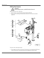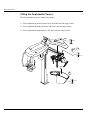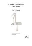
1
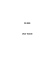
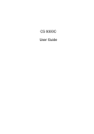
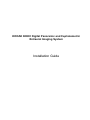
KODAK 8000C Digital Panoramic and Cephalometric
Extraoral Imaging System
Installation Guide
Notice
Congratulations on your purchase of the KODAK 8000C Digital Panoramic and Cephalometric Extraoral Imaging
System. Thank you for your confidence in our products and we will do all in our power to ensure your complete
satisfaction.
The Installation Guide for the KODAK 8000C Digital Panoramic and Cephalometric Extraoral Imaging System
includes information on the cephalometric features. For the panoramic features, see the KODAK 8000 Extraoral
Imaging System (SM721) Installation Guide. We recommend that you thoroughly familiarize yourself with this
Guide in order to make the most effective use of your system.
WARNING: We recommend that you consult the “Safety, Regulatory and the Technical
Specification User Guide” before using the KODAK 8000C Extraoral Imaging Systems.
The information contained in this Guide may be subject to modification without notice, justification or notification
to the persons concerned.
No part of this Guide may be reproduced without the express permission of Carestream Health, Inc.
The US Federal law restricts this device to sale by or on the order of a physician.
This document is originally written in English.
Manual Name: KODAK 8000C Digital Panoramic and Cephalometric Extraoral Imaging System Installation
Guide
Part Number: SM736
Revision Number: 02
Print Date: 03/2010
The brand names and logos reproduced in this Guide are copyright.
KODAK is a trademark of KODAK used under License.
KODAK 8000C Digital Panoramic and Cephalometric Extraoral Imaging System, complies with Directive
93/42/CEE relating to medical equipment.
.
0086
Manufacturer
Carestream Hea lth, Inc.
150 Verona Street
Rochester NY 14 608
Authorized Representative in the European Community
EC REP
TROPHY
4, Rue F. Pelloutier, Croissy-Beaubourg
77435 Marne la Vallée Cedex 2, France
Contents
1—About This Guide
Conventions in this Guide. . . . . . . . . . . . . . . . . . . . . . . . . . . . . . . . . . . . . . . . . . . . . . . . . . . . . . . . . . . . . . . . . . . . . 1–1
2—KODAK 8000C UNIT OVERVIEW
General Overview . . . . . . . . . . . . . . . . . . . . . . . . . . . . . . . . . . . . . . . . . . . . . . . . . . . . . . . . . . . . . . . . . . . . . . . . . . .
Mobile Components . . . . . . . . . . . . . . . . . . . . . . . . . . . . . . . . . . . . . . . . . . . . . . . . . . . . . . . . . . . . . . . . . . . . . .
General Functional Components . . . . . . . . . . . . . . . . . . . . . . . . . . . . . . . . . . . . . . . . . . . . . . . . . . . . . . . . . . . .
Digital Sensor Locations. . . . . . . . . . . . . . . . . . . . . . . . . . . . . . . . . . . . . . . . . . . . . . . . . . . . . . . . . . . . . . . . . . .
Laser Locations . . . . . . . . . . . . . . . . . . . . . . . . . . . . . . . . . . . . . . . . . . . . . . . . . . . . . . . . . . . . . . . . . . . . . . . . . .
Control Panel . . . . . . . . . . . . . . . . . . . . . . . . . . . . . . . . . . . . . . . . . . . . . . . . . . . . . . . . . . . . . . . . . . . . . . . . . . . . . . .
X-Ray Remote Control Overview . . . . . . . . . . . . . . . . . . . . . . . . . . . . . . . . . . . . . . . . . . . . . . . . . . . . . . . . . . . . . . .
Positioning Accessories and Replacement Parts . . . . . . . . . . . . . . . . . . . . . . . . . . . . . . . . . . . . . . . . . . . . . . . . . .
2–1
2–2
2–3
2–5
2–6
2–7
2–8
2–9
3—KODAK 8000C PACKAGING
Standard Packaging . . . . . . . . . . . . . . . . . . . . . . . . . . . . . . . . . . . . . . . . . . . . . . . . . . . . . . . . . . . . . . . . . . . . . . . . . 3–1
4—SITE PREPARATION BEFORE INSTALLATION
Standard Compliance . . . . . . . . . . . . . . . . . . . . . . . . . . . . . . . . . . . . . . . . . . . . . . . . . . . . . . . . . . . . . . . . . . . . . . . .
Environmental Requirements . . . . . . . . . . . . . . . . . . . . . . . . . . . . . . . . . . . . . . . . . . . . . . . . . . . . . . . . . . . . . . . . . .
Unit Dimensions . . . . . . . . . . . . . . . . . . . . . . . . . . . . . . . . . . . . . . . . . . . . . . . . . . . . . . . . . . . . . . . . . . . . . . . . . . . . .
Electrical Requirements. . . . . . . . . . . . . . . . . . . . . . . . . . . . . . . . . . . . . . . . . . . . . . . . . . . . . . . . . . . . . . . . . . . . . . .
X-Ray Room Requirement . . . . . . . . . . . . . . . . . . . . . . . . . . . . . . . . . . . . . . . . . . . . . . . . . . . . . . . . . . . . . . . . . . . . .
Computer System Requirements . . . . . . . . . . . . . . . . . . . . . . . . . . . . . . . . . . . . . . . . . . . . . . . . . . . . . . . . . . . . . . .
4–1
4–1
4–2
4–3
4–7
4–9
5—INSTALLING THE CEPHALOSTAT
Tool Requirements . . . . . . . . . . . . . . . . . . . . . . . . . . . . . . . . . . . . . . . . . . . . . . . . . . . . . . . . . . . . . . . . . . . . . . . . . . . 5–1
Technical Staff Requirements . . . . . . . . . . . . . . . . . . . . . . . . . . . . . . . . . . . . . . . . . . . . . . . . . . . . . . . . . . . . . . . . . . 5–1
Opening the Box . . . . . . . . . . . . . . . . . . . . . . . . . . . . . . . . . . . . . . . . . . . . . . . . . . . . . . . . . . . . . . . . . . . . . . . . . . . . 5–2
Installing the Cephalostat Unit . . . . . . . . . . . . . . . . . . . . . . . . . . . . . . . . . . . . . . . . . . . . . . . . . . . . . . . . . . . . . . . . . 5–3
Installing the Cephalostat Arm . . . . . . . . . . . . . . . . . . . . . . . . . . . . . . . . . . . . . . . . . . . . . . . . . . . . . . . . . . . . . . 5–3
Installing the Cephalostat Head. . . . . . . . . . . . . . . . . . . . . . . . . . . . . . . . . . . . . . . . . . . . . . . . . . . . . . . . . . . . . 5–5
Wiring the Cephalostat Head. . . . . . . . . . . . . . . . . . . . . . . . . . . . . . . . . . . . . . . . . . . . . . . . . . . . . . . . . . . . . . . 5–8
Wiring the Cephalostat to the Unit Head . . . . . . . . . . . . . . . . . . . . . . . . . . . . . . . . . . . . . . . . . . . . . . . . . . . . . 5–9
Post-Installation Control . . . . . . . . . . . . . . . . . . . . . . . . . . . . . . . . . . . . . . . . . . . . . . . . . . . . . . . . . . . . . . . . . . . . . 5–10
Adjusting the Cephalostat Head . . . . . . . . . . . . . . . . . . . . . . . . . . . . . . . . . . . . . . . . . . . . . . . . . . . . . . . . . . . 5–10
Adjusting the Cephalostat Head Inclination . . . . . . . . . . . . . . . . . . . . . . . . . . . . . . . . . . . . . . . . . . . . . . . 5–10
Adjusting the Height of the Cephalostat Head . . . . . . . . . . . . . . . . . . . . . . . . . . . . . . . . . . . . . . . . . . . . 5–12
Adjusting the Ear Cones Alignment . . . . . . . . . . . . . . . . . . . . . . . . . . . . . . . . . . . . . . . . . . . . . . . . . . . . . 5–14
Adjusting the Nasion Support . . . . . . . . . . . . . . . . . . . . . . . . . . . . . . . . . . . . . . . . . . . . . . . . . . . . . . . . . . . . . 5–15
Adjusting the Cephalometric Frankfurt Positioning Laser . . . . . . . . . . . . . . . . . . . . . . . . . . . . . . . . . . . . . . . 5–17
Checking the Image Quality . . . . . . . . . . . . . . . . . . . . . . . . . . . . . . . . . . . . . . . . . . . . . . . . . . . . . . . . . . . . . . . 5–18
Fitting the Covers. . . . . . . . . . . . . . . . . . . . . . . . . . . . . . . . . . . . . . . . . . . . . . . . . . . . . . . . . . . . . . . . . . . . . . . . . . . 5–20
KODAK 8000C Digital Panoramic and Cephalometric Extraoral Imaging System Installation Guide (SM736)_Ed 02
iii
Contents
Fitting the Cephalostat Covers. . . . . . . . . . . . . . . . . . . . . . . . . . . . . . . . . . . . . . . . . . . . . . . . . . . . . . . . . . . . . 5–22
6—Maintenance
Annual Maintenance. . . . . . . . . . . . . . . . . . . . . . . . . . . . . . . . . . . . . . . . . . . . . . . . . . . . . . . . . . . . . . . . . . . . . . . . . . 6–1
iv
Chapter 1
About This Guide
Conventions in this Guide
The following special messages emphasize information or indicate potential risk to
personnel or equipment:
WARNING
Warns you to avoid injury to yourself or others by following the
safety instructions precisely.
CAUTION
Alerts you to a condition that might cause serious damage.
IMPORTANT
Alerts you to a condition that might cause problems.
NOTE
Emphasizes important information.
TIP
Provides extra information and hints.
KODAK 8000C Digital Panoramic and Cephalometric Extraoral Imaging System Installation Guide (SM736)_Ed 02
1–1
Conventions in this Guide
1–2
About This Guide
Chapter 2
KODAK 8000C UNIT OVERVIEW
The KODAK 8000C digital panoramic and cephalometric unit is designed to carry out the
following radiological examinations:
•
•
•
•
•
•
•
•
Panoramic
Maxillary Sinus
Temporomandibular Joints (TMJ)
Lateral cephalometric
Frontal (PA or AP) cephalometric
Oblique cephalometric
Submento-vertex cephalometric
Carpus cephalometric
General Overview
The KODAK 8000C digital panoramic and cephalometric unit is composed of the
following functional components:
•
•
•
•
•
•
•
•
•
•
•
•
•
•
•
•
The unit head that contains all the electronic control
The rotative arm
The fixed arm with a control panel
The panoramic digital sensor
The x-ray source assembly
The x-ray remote control
The chin rest and bite block
The chin rest base
The panoramic chin rest and bite block
The temple supports
The hand grips
The cephalostat arm
The cephalostat head
The head clamps and ear cones
The nasion support
The acquisition software (see “Imaging Software Overview”)
The following figures illustrate the general overview of the KODAK 8000C digital
panoramic and cephalometric units.
KODAK 8000C Digital Panoramic and Cephalometric Extraoral Imaging System Installation Guide (SM736)_Ed 02
2–1
General Overview
IMPORTANT
The Cephalostat can be positioned either on the right or the
left side of the KODAK 8000 unit.
Mobile Components
Figure 2-1 illustrates the up and down movement of the KODAK 8000C digital
panoramic and cephalometric units mobile component and the rotation of the rotative
arm.
Figure 2–1
2–2
KODAK 8000C UNIT OVERVIEW
KODAK 8000 and KODAK 8000C Units Mobile Components
General Overview
General Functional Components
Figure 2-2 illustrates the general functional components of the KODAK 8000C digital
panoramic and cephalometric units.
Figure 2–2
KODAK 8000 and KODAK 8000C Units Functional Components
20
19
21
22
18
23
24
16
15
17
5
1
25
4a
14
29
2
4
3
28
3a
26
8
27
12
10
RJ45/1
RJ45/2
9
6
7
13
11
1
Height adjustment buttons
14
X-Ray source assembly
2
Control panel
15
Unit rotative arm
3
Hand Grip
16
Panoramic sensor
3a
Temple supports control knob
17
Component to raise for Cephalometric mode
4
Chin rest base
18
ON/OFF button
4a
Chin rest and bite block
19
Wall mounting brackets cover
5
Temple supports
20
Wall mounting brackets
6
Unit mains connecting terminal
21
Column upper cover
7
Green warning lamp (ready state indicator) 22
Panoramic head cover
8
Column connecting terminal
Cephalostat arm
23
KODAK 8000C Digital Panoramic and Cephalometric Extraoral Imaging System Installation Guide (SM736)_Ed 02
2–3
General Overview
2–4
9
X-Ray remote control
24
Cephalometric end of the arm cover
10
Door safety switch
25
Cephalostat head and head top cover
11
PC hosting the imaging and the acquisition 26
software
Cephalostat head side cover
12
Ethernet outlet RJ45/1
27
Carbon fiber screen
13
LAN RJ45/2
28
Head clamps and ear cones
29
Nasion support
KODAK 8000C UNIT OVERVIEW
General Overview
Digital Sensor Locations
Figure 2-3 illustrates the locations of the digital panoramic and digital cephalometric
sensors of the KODAK 8000C digital panoramic and cephalometric units.
Figure 2–3
KODAK 8000 and KODAK 8000C Units Digital Sensor Locations
system
KODAK 8000C Digital Panoramic and Cephalometric Extraoral Imaging System Installation Guide (SM736)_Ed 02
2–5
General Overview
Laser Locations
Figure 2-4 illustrates the location of the lasers of the KODAK 8000C digital panoramic
and cephalometric units.
Figure 2–4
KODAK 8000 and KODAK 8000C Units Laser Beam Locations
4
3
2
1
2–6
KODAK 8000C UNIT OVERVIEW
1
Mid-sagittal plane positioning laser beam
2
Frankfort plane positioning laser beam
3
Canine plane positioning laser beam
4
Cephalometric Frankfort plane positioning laser beam
Control Panel
Control Panel
The control panel is an alphanumeric, digital soft touch console. It allows the operator to
control certain unit functions. It also displays the operating parameters and error
messages.
Figure 2–5
Unit Control Panel
8
Digital Panoramic and Cephalometric System
kV
1
mA
S
2
3
4
1
X-Ray emission LED: Yellow, indicates the x-rays are being emitted.
2
Display Screen: Displays the current acquisition parameters and the error messages.
3
Reset button: Resets the unit arm to the initial position to enable the patient to enter
and exit the unit.
4
Laser beam button: Activates the laser positioning beams to correctly position the
patient.
KODAK 8000C Digital Panoramic and Cephalometric Extraoral Imaging System Installation Guide (SM736)_Ed 02
2–7
X-Ray Remote Control Overview
X-Ray Remote Control Overview
The x- ray remote control enables you to launch a radiological image acquisition via the
exposure button from outside the x-ray room. You must press and hold the exposure
button until the end of acquisition. Premature release of the exposure button interrupts
the acquisition.
Figure 2–6
X-Ray Remote Control
1
1
2–8
Exposure button: launches image acquisition.
KODAK 8000C UNIT OVERVIEW
Positioning Accessories and Replacement Parts
Positioning Accessories and Replacement Parts
The following accessories are used when positioning a patient. They are delivered with
the KODAK 8000 digital panoramic and KODAK 8000C digital panoramic and
cephalometric unit.
Table 2-1 and Table 2-2 list the panoramic and cephalometric positioning accessories.
Table 2–1
Panoramic Positioning Accessories and Replacement Parts
Accessory
Description
Panoramic chin rest and TMJ x2
Maxillary sinus chin rest
TMJ x2 and TMJ x4 nose rest
Standard bite block
Bite block for edentulous patients
A set of right and left temple supports
x2
Single use sheaths for bite blocks
(500 pcs box)
KODAK 8000C Digital Panoramic and Cephalometric Extraoral Imaging System Installation Guide (SM736)_Ed 02
2–9
Positioning Accessories and Replacement Parts
Accessory
Description
Head clamps with ear cones
x2
Nasion support
2–10
KODAK 8000C UNIT OVERVIEW
Chapter 3
KODAK 8000C PACKAGING
Standard Packaging
Table 3–1
Box
Cephalometric Assembly Components
Components
•
•
•
•
Table 3–2
Dimension (mm)
Weight
1200mm (L) x 800mm (D) x 1180mm (H)
80 kg
Cephalostat head
Cephalostat arm
Cephalostat covers
Documentation (User Guide and
Installation Guide)
Components
Product
Description
Quantity
Cephalostat head
1
KODAK 8000C Digital Panoramic and Cephalometric Extraoral Imaging System Installation Guide (SM736)_Ed 02
3–1
Standard Packaging
Table 3–2
Components (Continued)
Product
3–2
KODAK 8000C PACKAGING
Description
Quantity
Cephalostat arm
1
Arm elbow tube
1
End of the arm cover
1
Head top cover
1
Head side cover
1
Chapter 4
SITE PREPARATION BEFORE INSTALLATION
IMPORTANT
Prior to placing the order and before installation, carefully check the
following requirements for the x-ray room.
Standard Compliance
Install the unit in an x-ray room compliant with all official regulations applicable to
protection against radiation. This room must reduce the frequency interferences of the
30MHz to 1GHz band to at least 12db.
Environmental Requirements
Check the following ambient operating condition requirements of the x-ray room before
installing the unit:
•
•
•
Temperatures: 5 ~35 °C
Relative humidity: 30 ~ 85%
Atmospheric pressure: 700 ~ 1060 hpa
KODAK 8000C Digital Panoramic and Cephalometric Extraoral Imaging System Installation Guide (SM736)_Ed 02
4–1
Unit Dimensions
Unit Dimensions
1261 mm
(49.63")
406 mm
(15.98")
306 mm
(12.05")
10 mm
(0.38")
440 mm
(17.3")
1810 mm
(71.3")
The unit dimensions illustrated in the above figure are as follows:
•
•
•
•
Maximum height of the unit (2315mm)
Minimum (1687mm) and maximum (997mm) height of the chin rest
Minimum (1022mm) and maximum (1712mm) height of the ear cones
Width (2250mm) and depth (1261mm) of the unit
WARNING
If you need to add a base plate you must add 15mm to the height of the unit.
600
500
4–2
SITE PREPARATION BEFORE INSTALLATION
Electrical Requirements
Electrical Requirements
WARNING*
You MUST select the operating voltage when placing an order. The
operating voltage CANNOT be modified on site.
The unit can operate at:
•
•
100/110/130 V 50/60 Hz
230/240 V 50/60 Hz
Table 4–1
Optional Operating Voltages of the Unit
Nominal voltage *
(no load)
Minimum
Maximum
Maximum line
current
100 V - 130 V
90 V
143 V
20 A
230 V - 240 V
207 V
264 V
10 A
CAUTION
The power supply line must be equipped with a connection box that
ensures a constant connection. It must not be possible to connect the
unit to the power supply without using a tool. The unit must be
protected against any accidental disconnection.
If other units are installed on the same line, interference and voltage fluctuations can
cause the radiological unit to operate abnormally. We strongly recommend that a
separate electrical line be dedicated to supply power to the KODAK 8000C unit.
This line should be protected by a circuit breaker with a maximum current of:
•
•
•
16 A at 230/240 V
20 A at 110/130 V
A differential circuit breaker of 30 mA
KODAK 8000C Digital Panoramic and Cephalometric Extraoral Imaging System Installation Guide (SM736)_Ed 02
4–3
Electrical Requirements
Figure 4–1
Electrical Diagram of the X-ray Room and Connections
G
L
N
1
2
3
13
4
L
1A
5
6
N
RJ45
K8000C
8
L
N
12
10
7bis
9
L
N
7
11
4–4
1
General mains
2
Differential circuit breaker
8
Column connecting terminals
3
Red color actuator emergency stop push-button
9
X-ray remote control
4
Red color actuator emergency stop push-button
10 Door safety switch
5
Red warning lamp, power ON indicator
11
Mains outlet (for electric tools)
6
Unit mains connecting terminal
12
Ethernet outlet (RJ45/1)
7
Green warning lamp, ready state indicator
13
Contactor
SITE PREPARATION BEFORE INSTALLATION
7bis X-ray warning lamp connecting terminal
Electrical Requirements
A single-phase alternating current power supply is required.
The electrical installation specifications should be as follows:
Table 4–2
Electrical Installation Specifications
Supply Voltage
230V/240V
100V/110V
/ 130V
50/60 Hz
50/60 Hz
Electrical supply
6 kW
6 kW
Line current
required
16A
20A
For 30 m:
For 10 m:
2.5 mm2
2.5 mm2
0.5
0.12
30 mA
30 mA
Maximum current to
trip circuit breaker
16A
20A
Specifications of 2
red color actuator
emergency stop
push-button
250V 6A
250V 6A
UL listed
UL listed
Frequency
Cable cross-section
according to length
Max. line
impedance
Differential circuit
breaker (2)
Protect the power supply line with a
differential circuit breaker that trips at
maximum current.
•
(3) and (4)
•
•
•
Install these stop push-buttons to
simultaneously, switch off the
current to the active conductors
of the radiological installation and
exclude any other electric
equipment.
Locate (3) inside the x-ray room,
near the unit, for the operator to
quickly cut the power supply if
necessary.
Locate (4) outside the x-ray room,
near the x-ray remote control for
the operator to quickly cut the
power supply if necessary.
Maintain them in OFF (open)
position until a deliberate action
is performed.
KODAK 8000C Digital Panoramic and Cephalometric Extraoral Imaging System Installation Guide (SM736)_Ed 02
4–5
Electrical Requirements
Table 4–2
Electrical Installation Specifications (Continued)
Specifications of
the warning lamps
60 W
•
60 W
(5) and (7)
•
Locate the red warning lamp (5)
outside the x-ray room to indicate
the unit is active (1 lamp at each
access point).
Locate the green warning lamp
(7) outside the x-ray room to
indicate the ready state of the
unit for acquisition.
Contactor (13)
16A-250V
UL listed
20A-250V
UL listed
Door Safety Switch
(9)
1A / 250V
1A / 130V Optionally, connect the door safety
switch (9) that deactivates the x-ray
remote control if the door remains
open.
Use the following switches:
Emergency Stop Switch:
Manufacturer:
Ref:
Cutler-Hammer
•
•
E22AT111
E22AT112
Contactor:
Manufacturer:
Ref: LC1 D4011
Telemecanique
•
•
•
F6 (110/130 V - 60 Hz)
P5 (230/240 V - 50 Hz)
U6 (230/240 V - 60 Hz)
IMPORTANT
If you cannot use the above manufacturer devices, use an equivalent
emergency switch and contactor in the UL list with the same
specifications. For more information, see UL 2601.1 clause 22.7.
4–6
SITE PREPARATION BEFORE INSTALLATION
X-Ray Room Requirement
X-Ray Room Requirement
IMPORTANT
Use an appropriate wall fixing system suitable for the type of wall
construction. See the examples below.
The following illustrations provide examples of wall types and fixations.
2x
2x
16 mm
16 mm
2x
2x
16 mm
16 mm
Table 4–3
X-Ray Room Requirements
Room Components
Minimum Requirement
Comments
Width of the door
75 cm (30")
Height of the ceiling
240 cm (95")
Strength of the wall
Withstanding an extraction force of 150 kPa at It is the responsibility of the installer to
each point of attachment.
choose an appropriate fixing system that
withstands the extraction force.
Load-bearing capacity of the floor
500 kg/m2
Required space for the KODAK 8000
and K8000C units
2350 (L) x 1950 (D) x 2400 (H) mm
If needed, a shorter column is possible by
special order.
The floor must be solid and flat.
IMPORTANT
Install the unit where a minimum amount of space is provided to allow
easy access for the patient or the maintenance technician (see Figure
4-2).
KODAK 8000C Digital Panoramic and Cephalometric Extraoral Imaging System Installation Guide (SM736)_Ed 02
4–7
X-Ray Room Requirement
Figure 4–2
Minimum X-Ray Room Space Configuration for K8000 and K8000C
RJ45/1
RJ45/2
MINI 2350 mm
(92.52")
MINI 500 mm
(19.68")
13
12
9
10
6
5
7bis
11
3
4
9
10
5
7
3
Red color actuator emergency stop push-button
9
X-ray remote control
4
Red color actuator emergency stop push-button
10
Door safety switch
5
Red warning lamp, power ON indicator
11
Mains outlet (for electrical tools)
6
Unit mains connecting terminal
12
Ethernet outlet (RJ45/1)
7
Green warning lamp, ready state indicator
13
Local Area Network (LAN), (RJ45/2)
7bis
X-Ray warning lamp connecting terminal
WARNING
You MUST prepare the appropriate electrical requirements and
configurations of the x-ray room before installing the unit. You MUST
locate separately the following low voltage and high voltage
connections:
- Low Voltage: (12), (9), (10)
- High Voltage: (6), (5), (7bis)
4–8
SITE PREPARATION BEFORE INSTALLATION
Computer System Requirements
Computer System Requirements
To keep you always updated on the latest evolution of the minimum computer system
requirements for KODAK 8000C system software, this section is posted on site
MyTrophytec: http://www.mytrophytec.com, as a separate document with edition
number. Before any intervention on the client’s site, check first the MyTrophytec site for
the latest edition.
IMPORTANT
It is MANDATORY to check that the computer system configuration is
compatible with the computer system requirements for the KODAK
8000C software. If necessary you MUST update your computer system
configuration. KODAK 8000C MUST be connected to the computer via
a point-to-point Ethernet link and not via a LAN. DO NOT place the
computer and the peripheral equipment connected to it in the
immediate vicinity of the patient in the unit. Leave at least 1.5 m
distance from the unit. The computer and the peripheral equipment
must conform to the IEC 60950 standard.
KODAK 8000C Digital Panoramic and Cephalometric Extraoral Imaging System Installation Guide (SM736)_Ed 02
4–9
Computer System Requirements
4–10
SITE PREPARATION BEFORE INSTALLATION
Chapter 5-
INSTALLING THE CEPHALOSTAT
Tool Requirements
The installer must supply the following tools:
•
•
•
•
•
•
•
Power drill
Screws and heavy duty fixings
Spirit level
Measuring tape
Cutter
Metric Allen keys
Metric spanners
IMPORTANT
The tool references mentioned in this manual are ISO tool
references.
Technical Staff Requirements
The installation requires the following number of technicians:
Unit Component
Technicians
Arm
2
Head
2
KODAK 8000C Digital Panoramic and Cephalometric Extraoral Imaging System Installation Guide (SM736)_Ed 02
5–1
Opening the Box
Opening the Box
Before opening the cephalostat assembly box make sure that you have the required tool.
To open the cephalostat assembly box, follow these steps:
1. Remove the upper cardboard from the packaging. DO NOT cut through the
cardboard.
2. Remove the cephalostat arm.
3. Remove gently and set aside the cephalostat head cover.
4. Remove the protection elements. Lift off the packaging carton.
5. Remove gently the cephalostat head from the transport support and place it on the
ground.
6. Remove the other accessories.
5–2
INSTALLING THE CEPHALOSTAT
Installing the Cephalostat Unit
Installing the Cephalostat Unit
Before installing the cephalostat unit, make sure that:
•
•
•
The unit is switched off.
The head and generator covers are removed.
You have the required tools.
Installing the Cephalostat Arm
To install the cephalostat unit, follow these steps:
IMPORTANT
Make sure that the wall mounting bracket’s hole (A) is the furthest
from the wall before installing the cephalostat unit.
A
1. With the help of 1 person, position the cephalostat arm on the rear of the mobile
component of the column. To attach the arm, insert the screws on the column on the
lower holes (A). Insert and then tighten the fixing screws (C).
B
B
A
13
KODAK 8000C Digital Panoramic and Cephalometric Extraoral Imaging System Installation Guide (SM736)_Ed 02
5–3
Installing the Cephalostat Unit
2. Make sure that the tube (A) is for the appropriate side (by default it is for the right side
position of the ceph), if not, unscrew the fixing screws and reposition it for the
appropriate side. Insert all the way tube (A) inside the tube clamps (B) and screw in
the fixing nut.Tigten the fixing screws of the tube clamps (B).
B
A
4 mm
5–4
INSTALLING THE CEPHALOSTAT
Installing the Cephalostat Unit
Installing the Cephalostat Head
3. With the help of 1 person, lift the cephalostat head and insert the elbow tube (A)
inside the elbow tube clamps. Insert the elbow tube (A) as far as:
•
•
Left side ceph position, 7mm (B)
Right side ceph position, 22mm (C)
6 mm
B
7 mm
A
C
22 mm
4. Screw the fixing screws but do not tighten them.
KODAK 8000C Digital Panoramic and Cephalometric Extraoral Imaging System Installation Guide (SM736)_Ed 02
5–5
Installing the Cephalostat Unit
5. Correctly position the cephalostat head using a spirit level (C) placed as shown in the
figure. Tighten the fixing screws (B) to adjust with the spirit level (C).
4 mm
A
C
B
6. Correctly position the cephalostat head using a spirit level (D) placed as shown in the
figure. Tighten the fixing screws (C) to adjust with to the spirit level (D).
2.5 mm
4 mm
6 mm
A
x1
C
B
C
x1
D
5–6
INSTALLING THE CEPHALOSTAT
Installing the Cephalostat Unit
7. To adjust the height of the Cephalostat head, using a measurement tape, measure the
height from the floor to the middle of the collimator outlet (A). Measure the height
from the floor to the center of the ear cone ball (B). The measurements must be the
same (A = B). To adjust the height use the tube fixing nut (C), see step 2 of the
procedure.
A
=
B
8. Insert the cables (B) inside the elbow tube (A) tube.
A
B
KODAK 8000C Digital Panoramic and Cephalometric Extraoral Imaging System Installation Guide (SM736)_Ed 02
5–7
Installing the Cephalostat Unit
Wiring the Cephalostat Head
9. Pull the cables out of the elbow tube (A). Remove the adhesive tape. Connect the
following wiring in the following order:
Cable ...
On the ...
To ...
(B)
967/Alim Lambda/CN1
Power supply board
CN1
(C)
Green and yellow cable
Next to power supply box Ground screw
(D)
Ethernet Pano (with ferrite)
Control box
Pano
(E)
Ethernet Workstation (with ferrite)
Control box
Workstation
(F)
A14/CJ802/J5 (with ferrite)
Control box
Synchro
B
C
D
A
F
E
2.5 mm
5–8
INSTALLING THE CEPHALOSTAT
Installing the Cephalostat Unit
Wiring the Cephalostat to the Unit Head
10. Pull the cables out of the cephalostat arm. Pass the cables through the opening in the
column and attach them with a cable tie to avoid cable wear due to usage as shown
in the figure below. Connect the wiring in the following order:
B
40
39
CJ653
J4
E "R"
J6
A
J10
J5
1
J9
CJ699
39
40
B
C
1
J9
CJ699
E "L"
J1 1
CJ664
J1 0
D
1
J21
Cable ...
On the ...
To ...
(A)
967/CJ653/J10
CJ653
J10
(B)
Ethernet Pano
Ethernet Pano
(C)
Ethernet Workstation
Ethernet Workstation
(D)
CJ664/J21
CJ664
J21(adapter board CJ664 v4)
(E “R”)
39/CJ699/J9 & 40/CJ699/J9
CJ699
J9 (for right side ceph)
(E “L”)
39/CJ699/J9 & 40/CJ699/J9
CJ699
J9 (for left side ceph)
KODAK 8000C Digital Panoramic and Cephalometric Extraoral Imaging System Installation Guide (SM736)_Ed 02
5–9
Post-Installation Control
Post-Installation Control
Before the post-installation control, check that:
•
•
•
•
•
The installation of the unit is complete.
The installation of the KODAK dental imaging software is complete.
You have the test tool.
You have raised the digital sensor to ceph mode.
The unit is on.
Adjusting the Cephalostat Head
Adjusting the Cephalostat Head Inclination
To adjust the cephalostat head inclination, follow these steps:
1. Position the head clamps in a frontal AP position.
2. Access the Cephalometric Acquisition Window. In the Program pane, click
3. Launch an x-ray using the x-ray remote control. The head clamps must be correctly
and vertically positioned on the acquired x-ray image.
5–10
INSTALLING THE CEPHALOSTAT
.
Post-Installation Control
4. If needed, adjust the cephalostat head mechanically using the elbow tube for
horizontal inclination of the cepahlostat head. Untighten the fixing screws (A) slightly.
Use the fixing screws (B) to adjust the horizontal inclination. Tighten the fixing screws
(A) when you have reached the desired adjustment.
2.5 mm
4 mm
x4
A
x1
B
A
B
x1
KODAK 8000C Digital Panoramic and Cephalometric Extraoral Imaging System Installation Guide (SM736)_Ed 02
5–11
Post-Installation Control
Adjusting the Height of the Cephalostat Head
To adjust the height of the cephalostat head, follow these steps:
1. Position the head clamps in a lateral position.
2. Access the Cephalometric Acquisition Window. In the Program pane, click
.
3. Launch an x-ray using the x-ray remote control.
4. In the Imaging Window, on the drawing toolbar, click
. On the acquired image,
draw a line from the bottom of the image to the center of the ball (ear cone). The
resulting value must be:
•
•
Height: 30mm (± 5mm)
Length: 110mm (± 5mm)
30 mm (± 5 mm)
110 mm (± 5 mm)
5–12
INSTALLING THE CEPHALOSTAT
Post-Installation Control
5. If needed, adjust the height, using the cephalostat arm screws (A). Untighten slightly
the screws (A) and lift the cephalostat head to the correct height. Tighten the
cephalostat arm screws (A).
x4
A
KODAK 8000C Digital Panoramic and Cephalometric Extraoral Imaging System Installation Guide (SM736)_Ed 02
5–13
Post-Installation Control
Adjusting the Ear Cones Alignment
To adjust the ear cones alignment, follow these steps:
1. Position the head clamps in a lateral position.
2. Access the Cephalometric Acquisition Window. In the Program pane, click
.
3. Launch an x-ray using the x-ray remote control. The ear cone ball (A) must be at the
center of the head clamps circle (B).
4. In the Imaging Window, on the drawing toolbar, click
. On the acquired image,
draw a line from the center of the ball (A) to the center of the circle (B). The resulting
value must be ±1.5mm.
B
+1.5 mm
A
5–14
INSTALLING THE CEPHALOSTAT
Post-Installation Control
5. If needed, adjust the cephalostat head mechanically:
•
•
For a vertical adjustment, use the cephalostat arm screws (A).
For a horizontal adjustment, use the elbow tube clamps screws (B).
B
B
A
4 mm
Adjusting the Nasion Support
To adjust the nasion support, follow these steps:
1. Lower the nasion support to a vertical position.
2. Access the Cephalometric Acquisition Window. In the Program pane, click
.
3. Launch an x-ray using the x-ray remote control. The nasion support must be
perpendicular to the ear cones.
KODAK 8000C Digital Panoramic and Cephalometric Extraoral Imaging System Installation Guide (SM736)_Ed 02
5–15
Post-Installation Control
4. In the Imaging Window, on the drawing toolbar, click
. On the acquired image,
draw a perpendicular line between the center of the ear cones and the nasion support
holes to check that the nasion support is positioned vertically. The resulting value
must be A = B ±3mm.
A
B
3 mm
5. If needed, adjust the nasion support, using the nasion support fixing screws (A).
A
2 mm
5–16
INSTALLING THE CEPHALOSTAT
Post-Installation Control
Adjusting the Cephalometric Frankfurt Positioning Laser
To adjust the cephalometric Frankfurt positioning laser, follow these steps:
1. Remove the generator front cover.
2. Turn on the unit. On the control panel, press
beams.
to turn on the positioning laser
3. Make sure that the cephalometric Frankfurt positioning laser beam is projected in the
middle of the ear cone.
4. If needed, adjust the laser using the fixing screw of the laser socket.
5. Replace the generator front cover.
KODAK 8000C Digital Panoramic and Cephalometric Extraoral Imaging System Installation Guide (SM736)_Ed 02
5–17
Post-Installation Control
Checking the Image Quality
To check the image quality, follow these steps:
1. Raise the nasion support.
2. Open the head clamps.
3. Position the image quality phantom (A) at the center of the digital sensor.
A
4. Access the Cephalometric Acquisition Window. In the Program pane, click
5. In the Parameter pane, select:
•
•
•
64 Kv
15 mA
0.4 s
6. Launch an x-ray to acquire an image.
7. In the Imaging Window, on the acquired image, zoom on the value grid (B) of the
image quality phantom (A). The resulting value clearly visible must be minimum 2.5
(right, left, center and bottom).
Check that there is no splitting lines of the grid of the image quality phantom.
5–18
INSTALLING THE CEPHALOSTAT
.
Post-Installation Control
B
B
8. Save the image. Use this image as reference for a later image quality verification.
KODAK 8000C Digital Panoramic and Cephalometric Extraoral Imaging System Installation Guide (SM736)_Ed 02
5–19
Fitting the Covers
Fitting the Covers
WARNING
Before fitting the covers, you MUST switch off the unit.
Before fitting the covers, check that:
•
•
All the screws in the wall and the floor have been tightened.
All the screws attaching the head and the fixed arm to the column have been
tightened.
A
D
2x
M5x20
2x
M5x50
2x
M5x15
B
C
E
2x
M5x50
2x
M5x12
3 mm
To fit the covers, follow these steps:
1. Fit the upper cover (A) on the column. Fit the cover on the wall-bracket (B). Fit the
cover on the column connecting terminal (C) and tighten the fixing screws.
5–20
INSTALLING THE CEPHALOSTAT
Fitting the Covers
2. Fit the head cover (D) of the unit to the head chassis and tighten the fixing screws.
3. Fit under the head cover (E) and tighten the fixing screws.
4. Fit the inside column cover (F) and position and attach securely the ON/OFF button
to the cover with the fixing screws. Screw and tighten the fixing screws of the column
cover.
You can fit the cephalometric covers now.
KODAK 8000C Digital Panoramic and Cephalometric Extraoral Imaging System Installation Guide (SM736)_Ed 02
5–21
Fitting the Covers
Fitting the Cephalostat Covers
To fit the cephalostat covers, follow these steps:
1. Fit the cephalostat end of the arm cover (A) and screw the fixing screws.
2. Fit the cephalostat head side covers (B) and screw the fixing screws.
3. Fit the cephalostat head top cover (C) and screw the fixing screws.
C
M5x12
4x
A
2x
M5x16
B
5x
5–22
INSTALLING THE CEPHALOSTAT
M5x12
Chapter 6
Maintenance
Annual Maintenance
We recommend that a general inspection of the unit should be carried out every year by
an approved dental systems technician.
The inspection should cover the following points:
•
Check the attachment points to the floor and the wall.
•
Check all the mobile components of the unit.
•
Check the x-ray generator.
•
Check the alignment of the x-ray.
•
Make an image acquisition with the test tools and check the image.
•
Check the focal trough and the symmetry.
•
Check the degree of legibility of the labels.
•
Check for damage to cables, covers, oil leaks, etc.
If the results of any of these inspections are unsatisfactory, refer to the Service Manual in
order to rectify any problems.
If there is any doubt, do not operate the unit.
KODAK 8000C Digital Panoramic and Cephalometric Extraoral Imaging System Installation Guide (SM736)_Ed 02
6–1
Annual Maintenance
6–2
Maintenance