1
ENGLISH
user manual
3
Congratulations on your purchase of a Trophy radiography system. Thank you for
your confidence in our products and we will do all in our power to ensure your
complete satisfaction.
You now have the User Guide for the TROPHYPAN, the digital extra-oral X-ray
unit. We recommend that you thoroughly familiarize yourself with this Guide in
order to make the most effective use of your system.
The information contained in this Guide may be subject to modification
without notice, justification or notification to the persons concerned.
No part of this Guide may be reproduced without the express permission of
Trophy Radiologie S.A.
ENGLISH
The brand names and logos reproduced in this Guide are copyright.
RVG, STV, Digipan, Trophy, Trophy Radiologie and the TR logo are registered trade marks of
Trophy Radiologie. Microsoft, MS-DOS and Windows are trade marks or registered trade marks of
the Microsoft Corporation. All other names or products referred to in this document are only used
for the purpose of identification and may be the trade marks or registered trade marks of their
respective owners.
The RVG technology is the subject of an international patent registered by Trophy Radiologie.
This document was originally written in French.
Revision date: 04/2003
TROPHYPAN complies with Directive 93/42/CEE relating to medical equipment.
SM 189
TROPHYPAN USER GUIDE
5
Contents
NOTES FOR THE USER . . . . . . . . . . . . . . . . . . . . . . . . . . . . . . . . . . . 7
WARNINGS AND SAFETY INSTRUCTIONS . . . . . . . . . . . . . . . . . 8
SECTION 1: FUNCTIONAL DESCRIPTION
Functional description of the radiology unit . . . . . . . . . . . . . . . . . . 11
Operating controls . . . . . . . . . . . . . . . . . . . . . . . . . . . . . . . . . . . . . . 12
Operating controls on the panoramic unit . . . . . . . . . . . . . . . . . . . . . . . . 12
Operating controls on the PC . . . . . . . . . . . . . . . . . . . . . . . . . . . . . . . . . 12
Accessories . . . . . . . . . . . . . . . . . . . . . . . . . . . . . . . . . . . . . . . . . 13
SECTION 2: DATA PROCESSING CONFIGURATIONS REQUIRED
IN ORDER TO SAFEGUARD IMAGE QUALITY
Configuration of the display in Windows . . . . . . . . . . . . . . . . . . 15
Minimum configuration of the PC . . . . . . . . . . . . . . . . . . . . . . . 15
Quality of the monitors . . . . . . . . . . . . . . . . . . . . . . . . . . . . . . . 16
SECTION 3:THE GRAPHIC INTERFACE
Functional blocks . . . . . . . . . . . . . . . . . . . . . . . . . . . . . . . . . . . . 18
Other functions . . . . . . . . . . . . . . . . . . . . . . . . . . . . . . . . . . . . . . 19
Warning and indicator lamps . . . . . . . . . . . . . . . . . . . . . . . . . . . 21
SECTION 4: X-RAY PROCEDURES
Preparations before commissioning
or during a long period of inactivity . . . . . . . . . . . . . . . . . . . . . . 23
Step-by-step instructions for producing a TROPHYPAN image . . . 23
Procedures for positioning the patient
according to the selected program . . . . . . . . . . . . . . . . . . . . . . 24
Radiological settings . . . . . . . . . . . . . . . . . . . . . . . . . . . . . . . . . . . . . . . . . 24
Standard Panoramic program . . . . . . . . . . . . . . . . . . . . . . . . . . . . . . . . . . 26
Pediatric Panoramic program . . . . . . . . . . . . . . . . . . . . . . . . . . . . . . . . . . 28
Maxillary Sinuses program . . . . . . . . . . . . . . . . . . . . . . . . . . . . . . . . . . . . 29
2-Section Lateral TMJs program . . . . . . . . . . . . . . . . . . . . . . . . . . . . . . . . 30
4-Section Lateral TMJs program . . . . . . . . . . . . . . . . . . . . . . . . . . . . . . . . 31
Informations relative to dosimetry . . . . . . . . . . . . . . . . . . . . . . 32
SM 189
TROPHYPAN USER GUIDE
ENGLISH
Environment . . . . . . . . . . . . . . . . . . . . . . . . . . . . . . . . . . . . . . . . 15
6
SECTION 5:THE PRINCIPAL DIGITIZING TOOLS IN THE
TROPHY WINDOWS SOFTWARE PROGRAM
The TROPHYPAN toolbar . . . . . . . . . . . . . . . . . . . . . . . . . . . . . 33
Diagnostics image size . . . . . . . . . . . . . . . . . . . . . . . . . . . . . . . . 33
Display tips . . . . . . . . . . . . . . . . . . . . . . . . . . . . . . . . . . . . . . . . . 34
Tips on combining TMJs . . . . . . . . . . . . . . . . . . . . . . . . . . . . . . . 34
Printing the TROPHYPAN image . . . . . . . . . . . . . . . . . . . . . . . 34
Recording the TROPHYPAN image . . . . . . . . . . . . . . . . . . . . . . 35
Sharing TROPHYPAN images between different workstations . . . 35
SECTION 6:ADVICE ON SERVICING & MAINTENANCE
Daily maintenance of your panoramic unit . . . . . . . . . . . . . . . . 37
Monthly maintenance . . . . . . . . . . . . . . . . . . . . . . . . . . . . . . . . . 37
SECTION 7: ERROR DIAGNOSTICS
Description of the information messages . . . . . . . . . . . . . . . . . . . . 39
Diagnosis of possible technical problems . . . . . . . . . . . . . . . . . . . . . 39
Error messages identified by the unit . . . . . . . . . . . . . . . . . . . . . . . . . . . . 39
Rapid troubleshooting . . . . . . . . . . . . . . . . . . . . . . . . . . . . . . . . . . . . . . . 42
SECTION 8:TECHNICAL SPECIFICATIONS
General technical specifications . . . . . . . . . . . . . . . . . . . . . . . . . . . 43
International standards . . . . . . . . . . . . . . . . . . . . . . . . . . . . . . . . . . 44
Electromagnetic compatibility . . . . . . . . . . . . . . . . . . . . . . . . . . . . . . . . . 44
Conforming to IEC Standards 601.2.7 (1998) and 601-1 (1995) . . . . . . . . 44
Characteristics of the X-ray radiogenic assembly . . . . . . . . . . . . . . 46
Conforming to IEC Standard 601.1.3 (1994) . . . . . . . . . . . . . . . . . . . . . . 46
Conforming to IEC Standard 601.2.28 (1993) . . . . . . . . . . . . . . . . . . . . . 46
Characteristics of the radiogenic unit . . . . . . . . . . . . . . . . . . . . . . . . . . . . 47
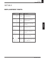
SECTION 9: REPLACEMENT PARTS . . . . . . . . . . . . . . . . . . . . . . . . 51
SM 189
TROPHYPAN USER GUIDE
Notes for the User
7
Notes for the User
X-rays are not innocuous and can be dangerous if not used properly. Therefore, the
instructions and warnings contained in this Guide must be carefully followed.
As a manufacturer of radiology units which conform to the most stringent
radiological protection standards in force throughout the world, Trophy’s knowhow guarantees the maximum degree of protection against radiation hazards.
Nonetheless, you are handling a radiology unit which is specially designed to emit
a dose of x-rays in order to carry out a medical diagnosis with the aid of a Trophy
digital imaging system (exclusive patent).
The room in which your radiology unit is to be installed must comply with all
official regulations applicable to protection against radiation.
Your dealer will be pleased to assist with the initial use of your radiology unit and
will supply any relevant information you may require.
The "WARNING" and "IONIZING RADIATION" symbols signify:
"WARNING: IONIZING RADIATION".
To install, operate and service the unit, follow the instructions contained in this
Guide.
ENGLISH
SM 189
TROPHYPAN USER GUIDE
8
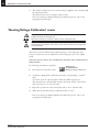
Warnings and safety instructions
Warnings and safety instructions
CAUTION Laser radiation. Do not look into the beam.
Class 2 laser product
This unit emits laser radiation.
For maximum safety, advise the patient not to look at the beam.
Before illuminating the beams, lower the Frankfurt plane beam to the lowest level.
While making adjustments, ensure that the beam is not directed into the patient’s
eyes.
DANGER This is an electrical unit. Do not expose it to water spray.
Such action may cause an electric shock or a malfunction of the unit.
WARNING The user is responsible for the operation and maintenance of this unit.
This unit must only be operated by legally qualified persons.
The cover of the unit must not be opened by the operator.
When necessary, inspection and maintenance operations should only be carried out
by an approved Trophy technician.
WARNING This unit must be installed in x-ray room which complies with current
installation standards.
From this location, visual or audio communication must be maintained with the
patient, together with access to the control interface during exposure.
WARNING The TROPHYPAN unit has been designed to comply with European and
international medical standards. In order to ensure conformity, the PCI interface board
must be installed in a computer configuration which conforms to IEC 950 Standard.
The PC and the peripheral equipment connected to it must not be located in the
immediate vicinity of the patient, thus at least 1.5 m from the panoramic unit.
For details of the data processing system (PC and screen), refer to the installation
guides for your computer. Sufficient clear space must be left around the CPU in order
to ensure that it is properly ventilated.
In order to obtain maximum image quality and visual comfort, the screen should be
positioned so as to avoid direct light reflections (internal or external lighting).
WARNING Do not operate the unit if there is the threat of an earthquake.
Following an earthquake, ensure that the unit is operating satisfactorily before
using it again.
Failure to observe this precaution may expose patients to hazards.
SM 189
TROPHYPAN USER GUIDE
Warnings and safety instructions
WARNING X-ray equipment can be hazardous to patients and the operator if the exposure
safety factors and operating instructions are not observed.
WARNING Do not place objects within the field of operation of the unit.
WARNING We recommend that the patient is wearing a protectrice lead-lined apron, unless
other Radiation Protection Protocols apply locally.
Ensure that any parts of the unit which may come into contact with the patient and the
operator have been disinfected after each patient has been exposed to X-rays.
While adjusting the height of the unit, the operator must ensure that the patient is kept clear
of the mechanism.
When the unit is not in use, ensure that the ON/OFF switch is set to OFF (O).
If the unit develops a fault, switch it off (O) and display a notice ‘Unserviceable’.
WARNING To dispose of the unit and/or its components, contact our representatives or our
Company.
WARNING Do not rotate the arm unit by hand as this may damage the unit.
WARNING The operator must ask the patient to refrain from moving during the entire period
of exposure.
WARNING The operator must ask the patient to refrain from moving until the ARM UNIT has
stopped moving and throughout the RESET movement.
SM 189
TROPHYPAN USER GUIDE
9
SECTION 1
Functional description
11
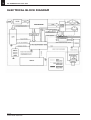
SECTION 1
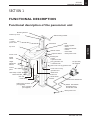
FUNCTIONAL DESCRIPTION
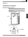
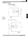
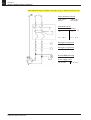
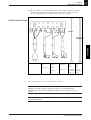
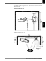
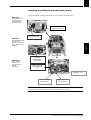
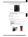
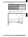
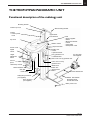
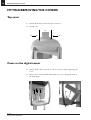
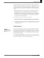
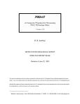
Functional description of the panoramic unit
Mounting bracket
Column top cover
Column
+ Column
power cords
Wall mounting bracket
Limit switch
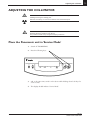
Top cover
Exposure button
Sensor cover
Rotating arm
+ Motor
+ Optical encoder
X-ray generator unit
+ Frankfurt laser
Digital
sensor
Height
adjustment
buttons
PC (IEC 950)
Not supplied
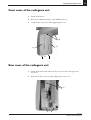
Rear cover of X-ray generator unit
Control
panel
Front cover of X-ray
generator unit
Head clamp control
Patient handles
Chin rest
Head clamp
Safety lamp connector
(not supplied)
Door connector
(not supplied)
Guide track
Junction box
+ electric linear
actuator
Panoramic RS232 link
RS422 link between
the digital sensor
and the PCI board
Mains power cord
SM 189
TROPHYPAN USER GUIDE
ENGLISH
ON/OFF switch
Head
+ Power supplies
+ Filters
+ Electronics boards
+ Lasers
+ Limit switch
+ Head power cords
12
SECTION 1
Functional description
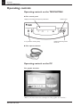
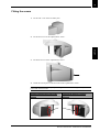
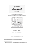
Operating controls
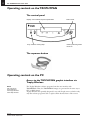
Operating controls on the TROPHYPAN
A/ The control panel
Display of the selected exposure parameters
X-ray emission warning lamp
Motion reset
Patient positioning lasers
turned on
B/ The exposure button
Operating controls on the PC
The graphic interface
(Refer to the next section for a description of the graphic user interface.)
SM 189
TROPHYPAN USER GUIDE
SECTION 1
Functional description
13
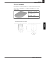
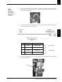
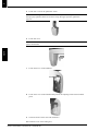
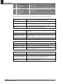
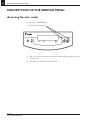
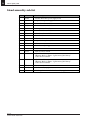
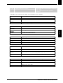
Accessories
The following accessories, used for positioning the patient, are supplied with the
unit in a separate carrying case:
Product
Code
Description
JR 265
Panoramic chinrest
(supplied fitted to the unit)
1
JR 263
Chinrest for the Maxillary
Sinuses program
1
JR 264
HT 182
Nasal support for the TMJ
1
program
6
Standard bite block
Bite block for
2
‘Edentulous patients’
FC 020
Bite block mounting
2
BD 103
Plastic-coated protective covers
(box of 500 items)
1
SM 189
TROPHYPAN USER GUIDE
ENGLISH
HY 048
Quantity
SECTION 2
Data processing configurations required in order to safeguard image quality
15
SECTION 2
DATA PROCESSING CONFIGURATIONS
REQUIRED IN ORDER TO SAFEGUARD
IMAGE QUALITY
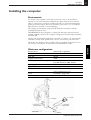
Environment
For details of the data processing hardware (PC, monitor, printer), refer to the
installation and user guides for your PC. Sufficient space must be left around the
PC in order to provide satisfactory ventilation. To benefit from the enhanced
image quality and for greater visual comfort, the screen should be oriented is such
a way as to prevent direct reflections of light (room lighting and daylight).
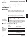
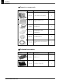
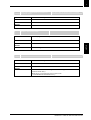
Configuration of the display in Windows
NOTE
For optimal visual comfort
it is recommended that
TROPHYPAN should be
used in 1024 x 768 mode.
Color
800x600
1024x768
1200x1024
True color
24 bits
RVG
TROPHYPAN
STV
RVG*
TROPHYPAN*
STV*
RVG*
TROPHYPAN*
STV*
True color
32 bits
RVG
TROPHYPAN
STV
RVG*
TROPHYPAN*
STV*
RVG*
TROPHYPAN*
STV*
* This resolution is only possible with SVGA cards containing 4 MB of video memory.
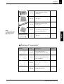
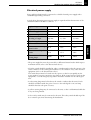
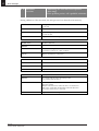
Minimum configuration of the PC
TROPHYPAN can only be used if the minimum configuration of the PC is as
follows:
NOTE
The minimum configuration
may change if an STV or
an RVG is connected to
the PC or if the Trophy
Management software
is used (refer to the
relevant installation
guides).
Microprocessor
Standards
Hard disk
Graphics card (SVGA)
RAM (random access memory)
Pentium III or equivalent
IEC 950
20 GB
4 MB
64 MB (Windows 98, 2nd edition),
128 MB (Windows 2000, XP, Me)
Operating system
Windows 98 (2nd edition), Me, 2000, XP
Type of PC
Multimedia
Available hardware slots
One PCI slot + One RS 232
serial communication port
Drivers
CD-ROM + floppy disk
Data backup system high capacity magnetic medium
SM 189
TROPHYPAN USER GUIDE
ENGLISH
Refer to the information in the table below to configure the graphics card
according to the Trophy imaging peripherals which have already been installed.
16
SECTION 2
Data processing configurations required in order to safeguard image quality
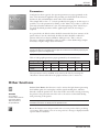
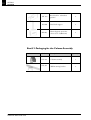
Quality of the monitors
Data processing monitors of different sizes are available (15-inch, 17-inch, 19-inch
and 21-inch) as well as different qualities of tube (standard, high contrast, high
definition). Since the quality of the TROPHYPAN image is dependent on the
quality of the tube, the preferred choice is a monitor with high contrast and high
definition, characterized by its deep black tube. The size (pitch) of the smallest pixel
which can be displayed is equally important and determines the sharpness of the
display; the pitch should be as fine as possible. The monitor is the final link in the
digital imaging chain, so it must be selected with great care.
As far as flat-screen monitors are concerned, it is still difficult to find a version
which is capable of satisfactorily reproducing the gray scales. Low-cost products
with 15-inch screens should be avoided in favor of 17-inch versions. Particular
attention should be paid to the fields of view which are a feature of every flat
screen, as well as its luminosity. The higher the values for these parameters, the
better the screen.
SM 189
TROPHYPAN USER GUIDE
SECTION 3
The graphic interface
17
SECTION 3
THE GRAPHIC INTERFACE
The Trophy Windows software program forms the user interface with
TROPHYPAN. Thus, the TROPHYPAN images are generated in the same way as
STV or RVG images.
Trophy Windows was specially designed for use with Trophy sensors, which is why
only this software program is able to exploit all the characteristics of the sensors.
Acquisition icon
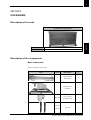
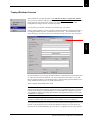
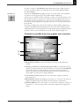
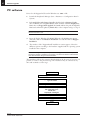
The configuration of the graphic interface is as shown below:
①
②
④
⑤
③
① Image Preview window: receives the image in real time as the tubehead is
rotated.
② Summary of Parameters and Selected Program window: confirms the current
settings of the panoramic unit. This information is stored in the TROPHYPAN
image and can be accessed by clicking on the image with the right mouse
button. It should be noted that this information is also incorporated in every
image which is printed out via Trophy Windows.
③ System Status window: displays the various messages originating from the
panoramic unit.
SM 189
TROPHYPAN USER GUIDE
ENGLISH
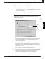
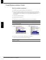
In order to acquire a TROPHYPAN image (Panoramic, Sinus, TMJ), begin by
selecting a patient medical record and then access the Trophy Windows Image
Processing Module.
Activate the TROPHYPAN graphic interface. To do this, click on the acquisition
icon (shown on the opposite page). The graphic interface is displayed.
At this stage it is possible to choose the type of image to be produced and to enter
the exposure parameters. All the actions initiated on the graphic interface have a
direct effect on the panoramic unit, to the extent that it is then only necessary to
position the patient and press the exposure button as soon as all the options have
been selected.
The image is displayed in real time in the Preview window. When acquisition is
complete, the graphic interface disappears from the screen and is replaced by the
Trophy Windows software program. The newly-acquired image is displayed in this
program so that it can be read with the aid of the various digital imaging tools.
NOTE
Also refer to the
User Guide and
the Trophy Windows
online Help function.
18
SECTION 3
The graphic interface
④ Main Window Selector. By clicking on the button or on the text, the User can
display the different functional blocks: Program, Patient or Parameters.
⑤ Functional Blocks: click on the button or on the names "Program", "Patient" or
"Parameters" to enter, in stages, all the information required for acquiring the
image.
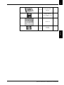
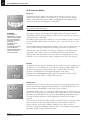
Functional blocks
Program
Configured as shown opposite, the Program block is used to select the type of
image to be produced. Click on the segments to be X-rayed (posterior, anterior,
TMJ or sinus). Only the segments which are highlighted on the display will be
exposed to the X-rays and will appear on the image.
NOTE Nonetheless, the areas are approximate and are dependent on correct positioning of
the patient and his/her morphology.
To produce a full panoramic image, the complete dental arch must be selected.
ATTENTION
This diagram is a representation
of the jaw, viewed from the
patient. The right side diagram
shows the right side of the
patient.
Depending on the configuration
of Trophy Windows (refer to the
‘Preferences’ menu) the image
may be viewed in mirror effect
or as shown above.
The Maxillary Sinuses program cannot be activated at the same time as a segment
of the dental arch or the TMJs.
The TMJ program is selected by clicking on one of the TMJs. It consists of views of
the left and right TMJs with the mouth either open or closed (at the choice of the
operator).
A 4-view TMJ image can be produced by clicking on the "x4" icon. This consists of
views of the left and right TMJs with the mouth open and the mouth closed.
The panoramic unit then makes an initial pass. Acquisition of the image is then
suspended to allow time to issue new instructions for positioning the patient.
The panoramic unit then makes a return pass before recording the last two views.
If the ‘x4’ icon is not activated, the image is acquired at the end of the first pass.
Patient
Configured as shown opposite, the Patient block is used to select the morphology of
the patient to be X-rayed. First choose the basic morphology (Adult, Child), then
the relative morphology (small, medium, large). Accurate selection of these
parameters will influence the subsequent high quality of the image.
Example: If the Child/Medium morphology is selected while X-raying a rather
stout adult, the image will be too light (under-exposed).
SM 189
TROPHYPAN USER GUIDE
SECTION 3
The graphic interface
19
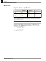
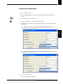
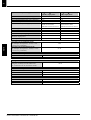
Parameters
Configured as shown opposite, the exposure parameters are preprogrammed on the
basis of the information supplied in the preceding two functional blocks. However,
the kilovolt (kV) and milliampere (mA) values can be modified.
Then simply click on the + et – buttons provided for this purpose. At this stage it is
possible to store the parameters by clicking on the "Mem" key in order to retain the
previously-selected modifications to the size and morphology. If the "Mem" key is
not used, the default parameters will be applied again when the next image is
acquired.
As a general rule, the kilovolt values should be increased if the bone structure of the
patient is dense. On the other hand, the kilovolt values should be reduced for
patients with low bone density (children, elderly persons). Thus, it may be
necessary to adjust the milliampere values in order to obtain darker images (higher
mA values) or lighter images (lower mA values).
NOTE The higher the kilovolt values, the lower the contrast on the image. However, the
clinical information is incorporated in the image and it can then be revealed by deploying the
Highlight tool (refer to the digital tools).
ENGLISH
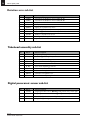
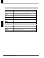
Table of radiographic parameters preprogrammed by the manufacturer:
Morphology
Parameters
Child
Adult
Small
kV
70
70
mA
5.0
8.0
Medium
kV
70
70
mA
8.0
10.0
Large
kV
70
70
mA
10.0
12.0
These parameters can be modified at any time by the User by accessing the
"Parameters" functional block in the graphic interface (refer to Section 2).
Other functions
WARNING
Do not direct t
he laser beams into the
eyes of the patient.
Warn the patient of
the potential risk.
Activate Laser Beams: this function is used to activate the light beams representing
the Frankfurt plane, the canine plane and the sagittal-median plane, which are
directed toward the patient’s face. These laser beams assist with correctly positioning
the patient in the panoramic unit. Also refer to the section of this Guide dealing
with positioning of the patient.
NOTE The light beams are automatically turned off after a few seconds. They can be
reactivated from the PC or directly from the panoramic unit.
Reset: this function resets the panoramic unit to its start position before producing
a new image. If the camera is not in its start position, a message is displayed and the
exposure button is disabled.
SM 189
TROPHYPAN USER GUIDE
20
SECTION 3
The graphic interface
X-rays ON/OFF: this function is used to operate the panoramic unit without
emitting X-rays ("X-Rays OFF" mode). If the X-ray emissions are turned off, the
message ‘Demo’ is displayed in the status window in place of the "Ready" message.
NOTE In order to instill an atmosphere of confidence in children, it is possible to position
them and simulate the acquisition of an image before actually acquiring the image.
Sound ON / OFF: this function is used to mute the audible messages emitted by
the graphic interface .
Information: this function is used to identify the unit (by its serial number) and the
installed software program. It can also be used to reinitialize the camera and to load
the default parameters set by the manufacturer.
Exit from the TROPHYPAN graphic interface: this function is used to return to
Trophy Windows. Warning: any modifications to the exposure parameters which
have not been stored will be lost. If this button is pressed during the acquisition of
an image, the emission of X-rays is immediately interrupted.
NOTE Do not exit from the Control Panel while an image is being acquired, otherwise it will
be irrevocably lost.
NOTE The emission of X-rays is only possible if the graphic interfaceof the panoramic unit is
active (PC turned on and control window in the foreground and visible). In this case, the
message "Ready" is displayed.
SM 189
TROPHYPAN USER GUIDE
SECTION 3
The graphic interface
21
Warning and indicator lamps
Generator ready
When this symbol is green, the generator is emitting X-rays when the exposure button
is activated. When it is black, the exposure button is disabled, preventing the emission
of X-rays.
This symbol changes color when the "X-Rays ON/OFF" button is pressed (refer to
the earlier section in this Guide).
If the generator is not ready, a message is displayed in the System Status window,
indicating the action to be taken in order to be able to produce an image (this
message is associated with a code, enabling more detailed information to be found
in this Guide). Otherwise, the "Ready" message is displayed.
If this symbol is yellow, X-rays are being emitted.
Thus it is normal for this symbol to change to black during the production of
images comprising non-adjacent blocks, since the X-rays are not emitted while the
generator is being moved toward the next zone to be X-rayed. In every other case,
the symbol is black.
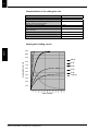
Cooling of the generator
The countdown indicates the time required for cooling the generator before a new
image can be produced with the selected exposure parameters (mm:ss). Until this
count reaches zero, the exposure button is disabled and the "Generator Ready" icon
is black.
This cooling period varies automatically according to the frequency of image
acquisitions and the selected parameters. This is a safety precaution designed to
guarantee the operating life of the generator.
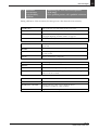
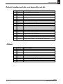
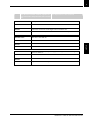
Cooling-off time between 2 image acquisitions:
Program
Full Panoramic
Full Panoramic
Full Panoramic
Full Panoramic
Exposure
parameters
Cooling
period
60 kV – 2 mA
70 kV – 10 mA
90 kV – 10 mA
80 kV – 15 mA
10 seconds
1 minute 10 seconds
1 minute 40 seconds
2 minutes 50 seconds
SM 189
TROPHYPAN USER GUIDE
ENGLISH
NOTE Also refer to the safety regulations relating to protection against ionizing radiation, as
applied in the User’s country.
SECTION 4
X-ray procedures
23
SECTION 4
X-RAY PROCEDURES
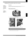
Preparations before commissioning
or during a long period of inactivity
By virtue of its technology, the TROPHYPAN is very easy to use and does not
require any special procedures before it is commissioned.
However, to increase the operating life of the X-ray tube, if the unit has not been
used for several days it is recommended that the following procedure should be
applied
(while observing the safety regulations for protection against X-rays and with no
patient in the unit):
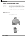
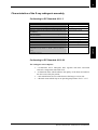
Step-by-step instructions for acquiring a
TROPHYPAN image
NOTE
The acquisition and
emission of X-rays
can be terminated at
any time by releasing
the exposure button.
1. Start Trophy Windows and open (or create) the medical record for the patient
concerned.
2. Access the Image Processing Module.
3. Click on the TROPHYPAN acquisition icon to open the graphic interface.
4. Check that the "Ready" message is displayed in the System Status window. If
it is not displayed, click on the "Motion Reset" button.
5. Choose the program and the patient type then, if necessary, adjust the kilovolt
and milliampere values.
6. In the Overview window check that the selected parameters conform to the
examination you wish to perform.
7. Position the patient in the unit, rigorously observing the instructions specified
in the "Patient Positioning" section of this Guide (see below). These
instructions vary according to the selected program.
8. Leave the irradiation field and initiate acquisition of the image, holding down
the exposure button until the image has been acquired.
9. The image is displayed in real time in the Preview window.
10. Verify that the image quality is satisfactory (positioning, etc.).
11. Release the patient.
12. Analyze the image, making use of the Trophy Windows image processing
tools.
SM 189
TROPHYPAN USER GUIDE
ENGLISH
1. Set the camera to 70 kV – 6.3 mA and produce a panoramic image.
2. Set the camera to 80 kV – 10 mA and produce a panoramic image.
3. Set the camera to 85 kV – 10 mA and produce a panoramic image.
You can then use the unit in the normal way.
24
SECTION 4
X-ray procedures
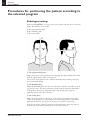
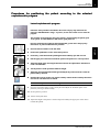
Procedures for positioning the patient according to
the selected program
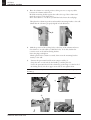
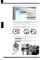
Radiological settings
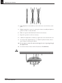
With the TROPHYPAN, you can position your patient with the aid of 3 reference
planes, identified by 3 laser beams:
① The sagittal-median plane
② The Frankfurt plane
③ The canine plane
①
②
➂
① The sagittal-median plane
Adjust the position of the patient’s face by aligning the sagittal-median laser beam
with the sagittal-median plane of the patient.
The position of the patient’s face is adjusted manually and is held in position by
the 2 lateral head clamps.
② The Frankfurt plane
Adjust the Frankfurt plane with the aid of the button which is accessible on the Xray generator unit. The laser beam must coincide with the auricular-orbital plane
of the patient. If necessary, adjust the height of the sliding unit, using the
adjusting buttons situated on the tubes.
③ The canine plane
Adjust the canine plane by centering it on the canine of the patient. The upper
canine of the patient acts as the reference for centering the patient in the section
plane. Ensure that the apex points of the incisors are visible on the image.
If this is not the case, adjust the position of the patient’s face. Move the chinrest
with the aid of the button situated in the center of the chinrest.
SM 189
TROPHYPAN USER GUIDE
SECTION 4
X-ray procedures
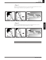
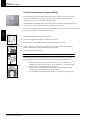
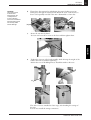
25
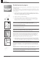
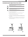
• Case 1:
If the laser beam from the canine is set too far away from the patient’s face, move the
chinrest support backward, using the graduation as a guide.
• Case 2:
NOTE Never exceed the limits of the graduation.
SM 189
TROPHYPAN USER GUIDE
ENGLISH
If the laser beam from the canine is set too close to the patient’s face, move the
chinrest support forward, using the graduation as a guide.
26
SECTION 4
X-ray procedures
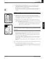
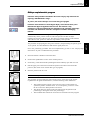
Standard panoramic program
The procedure for positioning the patient is described below. This procedure must
be rigidly observed.
It is summarized in point 7 of the step-by-step instructions described above. Once
the procedure has been implemented, follow the subsequent step-by-step instructions
as far as point 12.
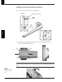
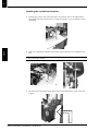
1.
Install the chinrest support and the bite block provided for the panoramic
type of image. Secure the support by rotating the adjusting button so that the
"0" reference is aligned with the reference mark.
2.
Open the side arms of the head clamp.
3.
Check that the "Ready" message is displayed on the control panel. If not,
press the "Reset Motion" button on the control panel or from the graphic
interfacein order to reset the arm to its initial position.
NOTE Ask the patient to remove any metallic object (spectacles, hearing aids, earrings,
necklaces, etc.) which may adversely affect the quality of the X-ray image.
We recommend that the patient is wearing a protectrice lead-lined apron, unless other
Radiation Protection Protocols apply locally.
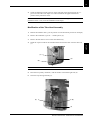
4.
Position the patient in the unit.
NOTE The patient must stand upright, with his/her hands on the lower handle and his/her feet
slightly forward. This positioning is essential in order to release the nape of the neck of the
patient and reduce the shadow of the column transferred to the image.
Adjust the height of the unit, using the buttons fitted to the vertical pillars. You
can activate one (or both) switches by simply pressing them. Then adjust the
height of the camera in such a way that the position of the chinrest support is at
the same height as the patient’s chin. Then release the button.
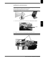
4.
5.
Ask the patient to bite into the recesses in the bite block and to place his/her
chin on the chinrest support. Ensure that the bite block is correctly centered
on the incisors and that the occlusion is produced in the recess of the bite block.
NOTE The bite block must be protected by a plastic-coated cover.
5.
If the patient is edentulous, or if the standard bite block is not compatible with
the dentition of the patient, you can replace it with the bite block for edentulous
patients.
If this bite block is not satisfactory, we advise you to remove the bite block and ask
the patient to bite on a cotton reel in order to slightly open his/her jaw.
NOTE The bite block for edentulous patients is not supplied with a protective plastic-coated
cover. For this reason, ensure that the bite block is sterilized using cold sterilization
techniques before using on another patient.
SM 189
TROPHYPAN USER GUIDE
SECTION 4
X-ray procedures
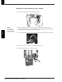
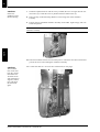
6.
27
Move the button of the Frankfurt plane to the lower position in order to
avoid directing the laser beam into the eyes. Turn on the laser beams by
means of the "Activate Laser Beams" button on the control panel of the
panoramic unit or on the graphic interface.
The laser beams can be turned on or off at any time by simply pressing the button.
In any event, the beams are automatically turned off after a period of 60
seconds.
WARNING Laser Radiation. Do not stare directly into the beam. Class 2 laser product.
8.
Adjust the button of the Frankfurt plane so that the light beam follows an
imaginary line which passes below the orbit of the patient and level with the
tragus. This adjustment can be made:
a. By means of the cursor located on the generator of the panoramic unit
a. And by adjusting the height of the unit in order to orientate the
patient’s head by rotation. The fixed point should be located level
with the recesses in the bite block.
7.
NOTE Check that the patient is still standing upright with his/her shoulders relaxed. His/her
hands should be holding the handle without applying any force. It is important that the patient
remains relaxed in order to prevent any movement while the tubehead is rotating and to lower
the shoulders.
9.
8. 9.
Ask the patient to smile, then check the alignment of the vertical beam with
the upper canine of the patient.
If this is not the case (due to major prognathous or other deformities in the
patient), the position of the patient must be adjusted in such a way that the
set of incisors is in the section plane.
Then move the chinrest, using the central button, so that the beam coincides
with the canine. Use the graduated scale as a reference. Do not exceed the
graduated scale.
Check that the sagittal-median plane and the Frankfurt plane are still correctly
adjusted.
10. Secure the side arms of the head clamp in order to immobilize the patient’s head.
11. The patient is ready for acquisition of the X-ray image.
Ensure that the patient’s shoulders are lowered and that his/her back is straight.
Ask him/her to remain immobile and to swallow so that his/her tongue is in
contact with the palate.
SM 189
TROPHYPAN USER GUIDE
ENGLISH
Adjust the position of the patient’s head in such a way that the sagittalmedian plane of the face coincides with the median beam. The reference line
is an imaginary line which passes through the center of the two incisors and
the mid-nasal point between the two ocular orbits.
FRANÇAIS
7.
28
SECTION 4
X-ray procedures
12. The image can now be acquired.
Make sure that you leave the room or that you move well away from the
camera in accordance with current regulations.
Press the exposure button, holding it down until the image has been acquired.
An audible beep and two yellow indicator lamps (one on the control panel
and one on the graphic interface) indicate that X-rays are being emitted. A
voice message reminds the patient to keep still.
In the event of a problem, you can interrupt the image acquisition process at
any time by releasing the exposure button.
In the event of a technical problem, a prompt is displayed on the graphic
interface and on the camera control panel. Make a note of the error code and
refer to the section "Technical Problems".
13. When the image has been acquired, check the quality of the image obtained,
then open the head clamp and release the patient.
WARNING When the "Reset Motion" button is pressed - the button is accessible from the
control panel or from the graphic interface-the arm rotates once before returning to its initial
position. Stand clear of the arc of rotation and ensure that the patient is immobile in the
panoramic unit.
The unit can be reset even if the patient is still in position in the panoramic unit. However, it is
essential to ensure that the patient does not move while the unit is rotating.
Pediatric panoramic program
Before acquiring an image of the child’s mouth, you can rotate the unit without
emitting X-rays, in order to reassure the child and explain to him/her how the
device works.
In this case, simply click on the icon "Rotation without X-rays" on the graphic
interface.
To disable this function, simply click on this icon again. Your panoramic unit is
now ready to acquire another image.
The procedure for positioning the patient is described below. This procedure must
be rigidly observed.
Follow the same procedure as described in the section "Step-by-step instructions
for producing a TROPHYPAN image". At point 5, click on the "child" icon to
select the type of patient.
The procedure for positioning the patient (point 7) must be exactly the same as
described in the Standard Panoramic program above.
SM 189
TROPHYPAN USER GUIDE
SECTION 4
X-ray procedures
29
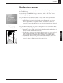
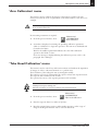
Maxillary sinuses program
The procedure for positioning the patient is described below. This procedure must
be rigidly observed.
Follow the same procedure as described in the section "Step-by-step instructions
for producing a TROPHYPAN image". At point 5, click on the "sinus" icon to
select the type of program.
SM 189
TROPHYPAN USER GUIDE
ENGLISH
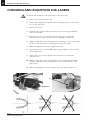
The procedure for adjusting the position of the patient in the section plane differs
slightly from the panoramic procedure:
• Adjust the position of the patient’s head so that the sagittal-median plane of
the face coincides with the median beam.
• Use the cursor, located on the casing of the panoramic unit, to set the level
of the Frankfurt plane. If it is not directed through the Frankfurt plan of
the patient, the laser beam must remain parallel to the Frankfurt plane.
• Check that the canine section plane beam coincides with the outer corner
of the eye. If necessary, rotate the adjustment button on the chinrest
support is order to slightly reposition the patient’s face.
FRANÇAIS
The procedure for positioning the patient (point 7) is the same as the Standard
Panoramic program described above, with the following minor differences:
• As the patient is being positioned in the panoramic unit, be sure to use a
chinrest support that is compatible with the "Sinus" mode. Secure the
support by rotating the adjusting button so that the "0v reference is aligned
with the reference mark.
30
SECTION 4
X-ray procedures
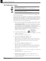
2-section lateral TMJs program
The procedure for positioning the patient is described below. This procedure must
be rigidly observed.
Follow the same procedure as described in the section "Step-by-step instructions
for producing a TROPHYPAN image". At point 5, click on one of the "TMJ"
icons to select the type of program. The "2-View Lateral TMJs" program is
selected.
At point 7, as the patient is being positioned in the panoramic unit, be sure to use
the nasal support designed for the "TMJ" program. Secure the support by rotating
the adjusting button so that the "0" reference is aligned with the reference mark.
a) Open the side arms of the head clamp.
b) Check that the "Ready" message is displayed on the control panel. If not, press
the "Reset Motion" button on the control panel or from the graphic interface
in order to reset the arm to its initial position.
NOTE Ask the patient to remove any metallic object (spectacles, hearing aids, earrings,
necklaces, etc.) which may adversely affect the quality of the X-ray image.
We recommend that the patient is wearing a protectrice lead-lined apron, unless other
Radiation Protection Protocols apply locally.
c) Position the patient in the panoramic unit.
NOTE The patient must stand upright, with his/her hands on the lower handle and his/her feet
slightly forward. This positioning is essential in order to release the nape of the neck of the
patient and reduce the shadow of the column transferred to the image.
NOTE
The beam of the
canine section plane
is not used for
positioning the patient
for the 2-Section TMJ
exposure program.
d) Adjust the height of the TROPHYPAN, using the buttons fitted to the vertical
pillars. You can activate one (or both) switches by simply pressing them.
Then adjust the height of the unit in such a way that the nasal support is in
contact with the patient’s nose. Then release the button.
e) Adjust the position of the patient’s head so that the sagittal-median plane of the
face coincides with the median beam.
f) Use the cursor, located on the casing of the panoramic unit, to set the level of
the Frankfurt plane.
If it is not directed through the Frankfurt plan of the patient, the laser beam
must remain parallel to the Frankfurt plane.
g) Secure the side arms of the head clamp in order to immobilize the patient’s head.
h) The patient is ready for acquisition of the X-ray image.
Ensure that the patient’s shoulders are lowered and that his/her back is straight.
Ask him/her to remain immobile and to swallow so that his/her tongue is in
contact with the palate.
SM 189
TROPHYPAN USER GUIDE
SECTION 4
X-ray procedures
j) When the image has been acquired, check the quality of the image obtained,
then open the head clamp and release the patient.
4-section lateral TMJs program
The procedure for positioning the patient is described below. This procedure must
be rigidly observed.
Follow the same procedure as described in the section entitled "2-Section Lateral
TMJs program".
As you select the program - after you have selected the TMJ program as explained
above, using the "2-Section Lateral TMJs program" procedure - click on the "x4"
icon which is displayed above the dental arch. The "TMJ 4 Lateral Views"
program is now selected.
You can confirm this from the "Overview" window to the left of the graphic
interface: an "x4" symbol is displayed in the top left corner of this window.
Then follow the instructions described in the "2-Section Lateral TMJs program"
procedure.
NOTE The 4-section TMJs procedure is implemented in 2 stages. Acquisition of the image is
interrupted after the initial rotation of the arm in order to allow the patient to change position
(mouth open or mouth closed).
When the first image has been acquired, the audible warning signal is turned off.
You can then release the exposure button. Approach the patient and then press the
"Reset Motion" key on the control panel in order to return the arm to the starting
position. Ensure that the patient remains immobile during this operation.
Ask the patient to open or close his/her mouth (changeover from mouth closed to
mouth open or vice-versa). Use the laser beams to ensure that the patient is still
positioned in the section plane.
SM 189
TROPHYPAN USER GUIDE
ENGLISH
WARNING When the "Reset Motion" button is pressed - the button is accessible from the
control panel or from the graphic interface - the arm rotates once before returning to its initial
position. Stand clear of the arc of rotation and ensure that the patient is immobile in the
panoramic unit.
The unit can be reset even if the patient is still in position in the panoramic unit. However, it is
essential to ensure that the patient does not move while the unit is rotating.
FRANÇAIS
i) The image can now be acquired.
Make sure that you leave the room or that you move well away from the camera
in accordance with current regulations.
Press the exposure button, holding it down until the image has been acquired.
An audible beep and two yellow indicator lamps (one on the control panel and
one on the graphic interface) indicate that X-rays are being emitted. A voice
message reminds the patient to keep still.
In the event of a problem, you can interrupt the image acquisition process at
any time by releasing the exposure button.
In the event of a technical problem, a prompt is displayed on the computer
interface system and on the TROPHYPAN control panel. Make a note of the
error code and refer to the section "Technical Problems".
31
32
SECTION 4
X-ray procedures
The image can now be acquired.
Make sure that you leave the room or that you move well away from the unit in
accordance with current regulations.
Press the exposure button to initiate acquisition of the second series of TMJ images.
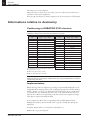
Informations relative to dosimetry
Conforming to EURATOM 97/43 directive
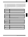
CAUTION This table provides you with an estimation of the emitted dose, which allows to
calculate the effective dose received by the patient for one image.
kV
60
61
62
63
64
65
66
67
68
69
70
71
72
73
74
mGy . cm2 / mAs
0,424
0,442
0,459
0,477
0,495
0,512
0,531
0,549
0,567
0,586
0,604
0,623
0,642
0,661
0,680
Dose measured at the exit of the primary collimator.
Dose precision: +/- 20 %.
Width of the primary slit: 0.5 mm
Height of the primary slit: 18.2 mm
kV
75
76
77
78
79
80
81
82
83
84
85
86
87
88
89
90
mGy . cm2 / mAs
0,699
0,719
0,739
0,758
0,778
0,798
0,818
0,839
0,859
0,880
0,900
0,921
0,942
0,963
0,985
1,006
CAUTION If your panoramic unit has a serial number prior to March 2003, the table
mentioned above is not appropriate. Please contact your Trophy certified dealer to obtain the
corresponding dose table.
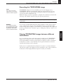
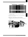
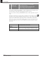
Implementation
When the image has been acquired, your image is automatically displayed in your
Trophy Windows imaging software. The radiological parameters used (for instance:
70 kV – 10 mA – 13.9 sec.) are displayed in the blue band at the top of the image.
To calculate the dose emitted by the unit, refer to the table mentioned below to
find out the coefficient corresponding to the kV value used to acquire the image.
This value is expressed in mGy.cm2/mAs.
As an example, for 70 kV, the corresponding value is 0.604 mGy.cm2/mAs.
Multiply this value by the mA and the time to get the emitted dose during the
acquisition.
At 70 kV, 10 mA and 13.9 secondes, the emitted dose is:
0.604 x 10 x 13.9 = 84 mGy.cm2
SM 189
TROPHYPAN USER GUIDE
SECTION 5
The principal digital tools in the Trophy Windows software program
33
SECTION 5
THE PRINCIPAL DIGITAL TOOLS IN THE
TROPHY WINDOWS SOFTWARE PROGRAM
The TROPHYPAN toolbar
NOTE
For information about
any buttons that are
not detailed below,
refer to the online
Help function of the
Trophy Windows
software program.
②
③
① Contrast filter: this tool is used to optimize contrast values. The filter is an
additional aid to enhancing the clinical details contained in the image.
However, it may have the effect of outlining amalgam fillings and crowns. It is
therefore advisable to confirm the diagnosis with this tool deactivated in order
to obtain a pure image which contains the complete clinical information.
② Highlight: this tool is used to enhance the contrast values on an area of interest
which has been previously selected in the image. It has the effect of emphasizing
details which are barely perceptible to the naked eye. This tool can be applied to
pure or filtered images, in window display mode, in full screen display mode
(image at a scale of 1:1) or in zoom display mode.
③ Measurement: this tool is used to make measurements on the image. It should
be noted that the validity of a given measurement is dependent on correct
positioning of the patient. In addition, a panoramic image, of necessity,
incorporates enlargements which are not consistent over the entire image.
It is strongly recommended that the Measurement tool is calibrated (refer to the
Trophy Windows Help function) using a ball of a known size in the area of
interest in which the measurement is to made.
NOTE Calibration using a ball indicates the magnification factor. Once the calibration process
has been completed, software-based compensation is only relevant in an area close to the
ball since, by definition, the magnification factors are not consistent over the entire image.
The measurements on the images should only be regarded as a general indication. It is
recommended that a supplementary measuring method should be used, in accordance with
accepted codes of practice.
Diagnostics image size
NOTE
The use of tools 1 and 2
and the display of the
diagnostics image size is
strongly recommended
as an aid to diagnosis.
The image can also be viewed at its true size by double-clicking on the image
(scale 1:1, one sensor pixel for each screen pixel). It is then possible to view all the
details contained in the image.
For details of the other buttons, refer to the Trophy Windows online Help function.
SM 189
TROPHYPAN USER GUIDE
ENGLISH
①
The TROPHYPAN toolbar, shown opposite, is displayed when a TROPHYPAN
image is active on the screen. It incorporates the following functions:
34
SECTION 5
The principal digital tools in the Trophy Windows software program
Display tips
The TROPHYPAN images are displayed in windows which can be moved across
the screen with the aid of the mouse. Three types of display can be selected by
clicking on different areas of the active window:
① These icons are located in the top right corner of the image window and can
be used to change the display from full screen mode to window mode.
Full screen
Window
② These icons, also located in the top right corner of the window, can be used
either to reduce the image to the form of an icon - which is then displayed at
the base of the screen and is restored by clicking on it - or to close the image.
Close
Minimize
③ The image can be displayed at its actual size, i.e. one pixel of the image is
represented by one pixel on the screen (scale 1:1).
Tips on combining TMJs
The procedure for converting 2-view images to 4-view images is as follows:
Two single TMJ images can be combined after they have been acquired, provided
that both images are associated with the same patient and were acquired on the
same date.
Then open the two images. Hold down the Ctrl button on the keyboard of the
PC and click on each of the images. Then request a combination of the images via
the Trophy Windows "File\Combination of TMJs" menu.
Printing the TROPHYPAN image
Images in TROPHYPAN Windows can be printed using any printer connected to
the PC and recognized by Windows. The natural preference is for a black-andwhite printer, either inkjet or thermal for optimal reproduction (some printers
which are only equipped with one color cartridge reproduce gray scales with the
aid of basic colors and, for this reason, the image quality is impaired).
NOTE Only large format black-and-white thermal printers are capable of producing filmquality printouts. Warning: In view of the diversity of printers and their configuration, the scale
of the image is never guaranteed and it is therefore strongly recommended that
measurements should not be made on the printed image.
SM 189
TROPHYPAN USER GUIDE
SECTION 5
The principal digital tools in the Trophy Windows software program
35
Recording the TROPHYPAN image
NOTE
Also, refer to the online
Help function of the Trophy
Windows software program.
TROPHYPAN images can be saved. When you close the Imaging screen,
TROPHYPAN Windows automatically checks any images that have not been
saved and, for each one, asks whether it should be saved. The saved images are
stored in the Patient Medical Record.
When the image is saved, it is possible to complete the comments associated with
the images (the default comments being the exposure parameters).
NOTE The comments can be edited and amended by clicking on the image with the right
mouse button.
WARNING
The complete information
is only retained if the image
is recorded in large format.
Compression may result in
a loss of clinical information.
It is strongly recommended that all the images should be saved in large format in
order to maintain the integrity of the clinical information. Compressed (small
format) images may be subject to irretrievable loss of information. The compressed
format is generally used to forward a copy to a third party, either by e-mail or on a
floppy disk.
As soon as they have been saved in the patient’s medical record, TROPHYPAN
images can be analyzed on each of the declared workstations in the network.
The Trophy Windows software program must be installed on all the consultation
workstations in order to ensure that the relevant patient medical record can be
opened and the images can be analyzed.
In this case, it is assumed that the information is stored on a common disk and
that the access path to the database has been specified for each of the consultation
workstations in the Trophy Windows Options (consult your installer).
SM 189
TROPHYPAN USER GUIDE
ENGLISH
Sharing TROPHYPAN images between different
workstations
SECTION 6
Advice on servicing and maintenance
37
SECTION 6
ADVICE ON SERVICING AND MAINTENANCE
Daily maintenance of your panoramic unit
Accessories
Servicing advice
Cold sterilization before
the next patient is X-rayed
Bite block for Edentulous patients
Cold sterilization before
the next patient is X-rayed
Head support
Before the next patient is X-rayed, the
head support and chinrest must be
disinfected with medical-grade alcohol
with an alcohol content in excess of 76%
Chinrest
(panoramic, sinus and TMJ)
All components which come into
contact with the patient and the
operator
Before the next patient is X-rayed, these
components must be disinfected with
medical-grade alcohol with an alcohol
content in excess of 76%
Outer covers of the panoramic unit
Wipe the TROPHYPAN with a dry
cloth and the end of each day’s
operation
WARNING Ensure that the TROPHYPAN unit is turned off before cleaning. Do not allow
liquid to penetrate inside the unit. Do not use detergents or solvents to clean the covers of
the panoramic unit.
Monthly maintenance
Accessories
Servicing advice
Outer covers of the panoramic unit
Wipe the TROPHYPAN with a soft dry
cloth
SM 189
TROPHYPAN USER GUIDE
ENGLISH
Standard bite block
SECTION 7
Error diagnostics
39
SECTION 7
ERROR DIAGNOSTICS
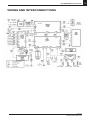
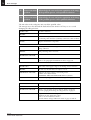
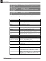
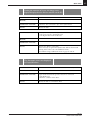
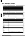
Information of the information messages
Code
Action
11
X-ray tube cooling
Cooling in progress.
Wait until the counter has reached zero.
12
Thermal security
Cooling in progress.
Wait until the counter has reached zero.
13
Release handswitch
Release the exposure button. Reinitialize the
movement and restart the exposure.
I6
Wrong arm position
The movement is not in its starting position,
so the exposure button is inactive.
Reinitialize the movement of the camera unit.
I 15
Interface inactive
Check that TROPHYPAN is actually turned on.
Check that only the TROPHYPAN graphic
interface is displayed on the screen,
to the exclusion of any other menu.
Diagnosis of possible technical problems
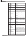
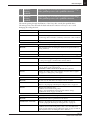
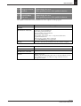
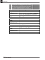
Error messages identified by the unit
In the event of a malfunction or an incorrect action by the operator, a message
- accompanied by an error code - is simultaneously displayed on your control panel
and on your graphic interface. A warning is also issued in the form of a voice message.
Please refer to the following table and follow the relevant instructions.
If the malfunction persists or the type of fault is not described, please contact an
approved Trophy dealer.
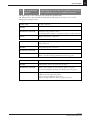
Code
Message
Action
E1
"Handswitch was
was released before
the end of exposure"
The X-ray exposure button has been released
prematurely.
Restart acquisition of the image if it is not
satisfactory.
E2
"Mains power failure
detected"
Acknowledge the error and restart acquisition of
the image.
If the problem persists, check the electrical
installation of the panoramic unit.
E3
"kV measurement
problem"
Acknowledge the error and restart acquisition of
the image.
If the problem persists, call a qualified technician.
E4
"kV measurement
problem"
Acknowledge the error and restart acquisition of
the image.
If the problem persists, call a qualified technician.
SM 189
TROPHYPAN USER GUIDE
ENGLISH
Message
40
SECTION 7
Error diagnostics
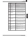
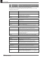
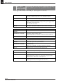
Code
SM 189
TROPHYPAN USER GUIDE
Message
Action
E6
"Problem inside
generator"
Acknowledge the error and restart acquisition of
the image.
If the problem persists, call a qualified technician.
E7
"mA measurement
problem"
Acknowledge the error and restart acquisition of
the image.
If the problem persists, call a qualified technician.
E8
"mA measurement
problem"
Acknowledge the error and restart acquisition of
the image.
If the problem persists, call a qualified technician.
E9
"Filament heating
problem"
Acknowledge the error and restart acquisition of
the image.
If the problem persists, call a qualified technician.
E 10
"Filament heating
problem"
Acknowledge the error and restart acquisition of
the image.
If the problem persists, call a qualified technician.
E 11
"Safety device activated
on high voltage
capacitors"
Acknowledge the error and restart acquisition of
the image.
If the problem persists, call a qualified technician.
E 12
"Problem with switch"
Acknowledge the error and restart acquisition of
the image.
If the problem persists, call a qualified technician.
E 13
"Travel measurement
problem"
Acknowledge the error and restart acquisition of
the image.
If the problem persists, call a qualified technician.
E 14
"Travel measurement
reproducibility
problem"
Acknowledge the error and restart acquisition of
the image.
If the problem persists, call a qualified technician.
E 15
"Movement too long"
Acknowledge the error and restart acquisition of
the image.
If the problem persists, call a qualified technician.
E 16
"Movement too short"
Acknowledge the error and restart acquisition of
the image.
If the problem persists, call a qualified technician.
E 17
"Movement
measurement
reproducibility
problem"
Acknowledge the error and restart acquisition of
the image.
If the problem persists, call a qualified technician.
E 22
"Capture stopped.
Interface has
been masked"
The graphic interface of the panoramic unit
was closed during acquisition of the image.
The graphic interfacemust always be active
and it should be placed in the foreground before an
image can be acquired.
E 23
"No movement
detected"
Acknowledge the error.
If the problem persists, call a qualified technician.
E 24
"Heating voltage
self-calibration
timeout"
Acknowledge the error.
If the problem persists, call a qualified technician.
E 25
"Heating voltage
lower limit reached"
Acknowledge the error.
If the problem persists, call a qualified technician.
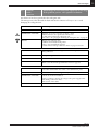
SECTION 7
Error diagnostics
Action
E 26
"Heating voltage
higher limit reached"
Acknowledge the error.
If the problem persists, call a qualified technician.
E 50
"Program evolution
problem"
Acknowledge the error.
If the problem persists, call a qualified technician.
E 51
"Serial Eeprom
read error"
Acknowledge the error.
If the problem persists, call a qualified technician.
E 52
"Communication
problem with
console"
Acknowledge the error.
If the problem persists, call a qualified technician.
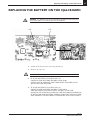
E 53
"Backup battery
out of service"
The operating life of the clock battery in the
panoramic unit is approximately 10 years.
Call a qualified technician to replace the battery.
E 54
"Inconsistency
in calibration
parameters"
Choose the ‘Restart’ option in the Error window.
If the problem persists, choose ‘Restore’ to
retrieve the result of the previous save operation.
If this fails to cure the problem, call a qualified
technician.
E 55
"Error in stored
parameters"
Choose the ‘Restart’ option in the Error window.
If the problem persists, choose ‘Restore’ to
retrieve the result of the previous save operation.
If this fails to cure the problem, call a qualified
technician.
E 56
"Error in
manufacturing
parameters"
Choose the ‘Restart’ option in the Error window.
If the problem persists, choose ‘Restore’ to
retrieve the result of the previous save operation.
If this fails to cure the problem, call a qualified
technician.
E 57
"Error in user
preferences"
Choose the ‘Restart’ option in the Error window.
If the problem persists, choose ‘Restore’ to
retrieve the result of the previous save operation.
If this fails to cure the problem, call a qualified
technician.
E 58
"Exposure context
error"
Acknowledge the error and check the selections
before reacquiring an image.
If the problem persists, call a qualified
technician.
E 59
"Program evolution
error"
Acknowledge the error.
If the problem persists, call a qualified
technician.
E 60
"Hardware error
detected"
Acknowledge the error.
If the problem persists, call a qualified
technician.
SM 189
TROPHYPAN USER GUIDE
ENGLISH
Message
FRANÇAIS
Code
41
42
SECTION 7
Error diagnostics
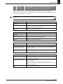
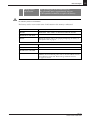
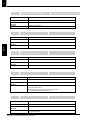
Rapid troubleshooting
The following information can be used without specialist knowledge to rectify the
majority of obvious malfunctions that may be encountered during use. The
information is based on the assumption that the system has been correctly
installed.
Try to rectify the malfunction by following the instructions given below.
If the malfunction persists or the of fault is not described, please contact an
approved Trophy dealer.
SM 189
TROPHYPAN USER GUIDE
Symptom
Cause and remedy
The TROPHYPAN graphic interface
is not displayed after clicking on the
acquisition icon in Trophy Windows
1- Check that the panoramic unit
has been switched on.
2- Ensure that all the connectors
between the panoramic unit and
the PC are in place.
3- Check that the driver for the PCI
card has been installed.
There is no movement when the
X-ray exposure button is pressed.
1- The ‘Ready’ message is not
displayed on the control screen.
Click on the ‘Reset Motion’
button to obtain the ‘Ready’
message.
2- The panoramic unit is in cooling
mode. Wait until the counter has
returned to zero.
3- The panoramic unit is in thermal
overload mode. Wait until the
‘Generator Ready’ icon changes
back to green.
No image appears on the screen
after the X-rays have been activated.
1- Ensure that the X-ray emissions
have not been deactivated.
2- Check the consistency of the
firing parameters (type of patient,
kV and mA values) with the
actual morphology of the patient.
The image contrast is satisfactory
but there are vertical faults (darker
strips).
1- During rotation, the patient’s
shoulders may have impeded the
movement of the generator,
reducing its speed and resulting
over-exposure of the image in
certain areas. Ensure that the
patient is correctly positioned.
The image is too dark
1- Reduce the dose of X-rays.
Begin by reducing the kV values,
followed by the mA values.
The image is too light
1- Increase the dose of X-rays.
Begin by increasing the kV values,
followed by the mA values.
SECTION 8
Technical specifications
43
SECTION 8
TECHNICAL SPECIFICATIONS
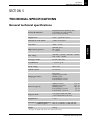
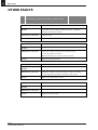
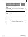
General technical specifications
Digital Panoramic Radiology Unit,
controlled from a PC interface.
Face-to-face positioning
Digital sensor
CCD + optical fiber sensor
Dimensions of the matrix
2,500 x 1,244 pixels
Gray scales
4,096 – 12 bits
High tension generator
140 kHz (max.)
60 - 90 kV
2 – 15 mA
Line voltage
230-240 V / 50 Hz , 230-240 V / 60 Hz
110 - 130 V / 60 Hz
Focal spot of tube
0.5 mm (IEC 336)
Total filtration
> 2.5 mm eq. Al
Anode voltage
90 kV max.
Cathode current
15 mA max.
Imaging procedures
Panoramic
Segmented panoramic
Maxillary sinus
Lateral TMJ, 2 sections
Lateral TMJ, 4 sections
Period of exposure
Adult panoramic:
Pediatric panoramic:
Maxillary sinus:
Lateral TMJ, 2 sections:
Lateral TMJ, 4 sections:
Exposure mode
2 programs (adult and child)
3 sizes (adjustable by the user)
Magnification
x 1.27
13.9 sec.
13.2 sec.
10.7 sec.
4.6 sec.
9.2 sec.
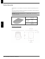
Dimensions (standard installation) 888 (L) x 1180 (D) x 2315 (H) mm*
(with base plate)
888 (L) x 1180 (D) x 2330 (H) mm
Weight
120 kg
* On request, the height of the column can be adjusted at the factory
SM 189
TROPHYPAN USER GUIDE
ENGLISH
Product identification
44
SECTION 8
Technical specifications
International standards
Electromagnetic compatibility
With regard to EMC, this product complies with European Directive 89/336/
CEE.
This product complies with European Standard EN 60601-1-2 ( 1993).
Its classification is Group I, Class B.
Conforming to IEC Standards 601.2.7 (1998) and
601-1 (1995)
MANUFACTURER:
TROPHY
4, rue F. Pelloutier, Croissy-Beaubourg
77437 Marne la Vallée Cedex 2, France
MODEL:
TROPHYPAN, radiographic dental diagnostic unit, IEC 601.2.7 ( 1998 ),
Class 1, Type B, Intermittent Operation,
with protection against X-rays complying with IEC 601.1.3 ( 1994 )
AMBIENT OPERATING CONDITIONS
Temperatures
5 ~35 °C
Relative humidity
30 ~ 85%
Atmospheric pressure
700 ~ 1060 hpa
STORAGE CONDITIONS
Temperature
Relative humidity
Atmospheric pressure
-10 ~ 60 °C
10 ~ 95%
700 ~ 1060 hpa
TRANSPORT CONDITIONS
Temperature
-10 ~ 60 °C
Relative humidity
10 ~ 95%
Atmospheric pressure
700 ~ 1060 hpa
SM 189
TROPHYPAN USER GUIDE
SECTION 8
Technical specifications
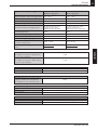
Type of electrical power supply:
230 - 240 V (± 10%)
110 -130 V (± 10%)
50/60 Hz, single-phase
60 Hz, single-phase
Apparent resistance of the power supply circuit
0.5 Ω (max.)
0.12 Ω (max.)
Permanent absorbed current
0.45 A
0.9 A
Current absorbed during the X-rays emission
9.5 A
17 A
Max. absorbed power
2.2 kVA
1.9 kVA
Protection for the power supply system
By shutter release at a max.
current of 16 A and a
differential current of 30 mA
By shutter release at a max.
current of 20 A and a
differential current of 30 mA
Nominal high tension
90 kV
90 kV
Maximum corresponding tube current
10 mA
10 mA
Nominal tube current
15 mA
15 mA
Maximum corresponding high tension
Tube current/voltage combination for
maximum output power
80 kV
68 kV
80 kV, 15 mA
85 kV, 12 mA
at 80 kV, 15 mA:
1200 W
at 85 kV, 12 mA:
1020 W
Nominal power for an exposure time
of 0.1 s.
Selection of the load parameters:
kV (in increments of 1 kV)
mA (in increments of 25%)
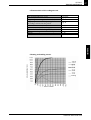
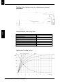
Cooling conditions:
Maximum dissipation of heat from the X-ray
radiogenic assembly into the ambient air
(for a utilization rate in continuous mode):
Details of the load parameters:
High tension:
Current in the tube:
Exposure time:
Measurement conditions:
KV
MA
Exposure time:
ENGLISH
Utilization rate in continuous mode
(for example: one exposure – 85 kV, 5 mA –
13.9 sec every 3 minutes)
Utilization rate in intermittent mode
(for example: one exposure – 80 kV, 15 mA –
13.9 sec every 3 minutes)
45
33 W.
93 W.
From 60 to 90 kV
From 2 to 15 mA
70 W
kV ± 10%
mA ± 20%
seconds ± (10% + 1ms)
Indirect on the peak kilovoltmeter
Direct measurement in the circuit using an oscilloscope
Measurement at 75% of the kV values
SM 189
TROPHYPAN USER GUIDE
46
SECTION 8
Technical specifications
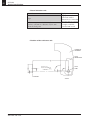
Characteristics of the X-ray radiogenic assembly
Conforming to IEC Standard 601.1.3 (1994)
IEC Standard 601.1.3 (1994)
Nominal value of the inherent filtration at 70 kV
Nominal value of the supplementary filtration
at 70 kV
Nominal value of the total filtration
at 70 kV
Filtration value for the enclosure of the
radiogenic unit (at 100 kV)
Filtration value for the enclosure of the image
receiver unit (at 100 kV)
Filtration value for the sensor case
Value for the arms of the head clamp (at 100 kV)
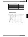
Distance between the focal spot and the sensor
Location of the reference axis
Size of the beam at the sensor
Radiation leakage after one hour’s operation
(maximum utilization rate of 93 W, i.e. 90 kV , 10 mA ,
13.9 sec. every2 minutes 15 sec.)
Compliant
2.8 mm (0.11'') eq. Al
Not applicable
2.8 mm (0.11'') eq. Al
0.2 mm (0.08") eq Al
0.2 mm (0.08") eq Al
0.8 mm (0.31") Al
1.0 mm (0.039") eq Al
522 mm ( 20.55 ". )
Refer to the diagram below
5 x 126 mm
< 1 mGy
Conforming to IEC Standard 601.2.28 (1993)
The radiogenic unit comprises:
• a transformer and a radiogenic tube, together with their
associated electronic components immersed in oil.
• an aluminum filter which enhances the quality of the beam and
reduces the dose received by the patient.
• a unit which limits the size of the beam at the image receiver unit.
• a thermal cutout which trips at an operating temperature of 65 °C
± 5 °C.
SM 189
TROPHYPAN USER GUIDE
SECTION 8
Technical specifications
47
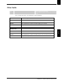
• Characteristics of the radiogenic unit
IEC Standard 601.2.28 (1993)
Manufacturer
Degree of protection against electric shock
Degree of protection of the parts applied to
the leakage current from the patient
Maximum accumulated heat
Maximum continuous heat dissipation
Nominal value of the focal spot (IEC 336/192)
Tolerances on the position of the focal spot
Weight
Dimensions
Compliant
Trophy
Class I
Type B
110 kJ
33 W.
0.5 mm
+/- 2.5 mm
8.2 kg
235 x 245 x 120 mm
ENGLISH
Accumulated heat in kJ
• Heating and cooling curves:
Cooling
Time in minutes
SM 189
TROPHYPAN USER GUIDE
48
SECTION 8
Technical specifications
• Beam limitation unit:
Manufacturer
Trophy
Rigidly mounted unit
with fixed window
dimensions, not removable
dand integrated x-ray generator
Type
Maximum symmetrical field of radiation
5 mm to 126 mm at a distance of 522 mm
from the focal point
Complies with IEC
Standard 806 (1994)
• Position of the reference axis:
TUBEHEAD
ASSEMBLY
X-RAY
GENERATOR
X-RAY
TUBE
REFERENCE
AXIS FOR TH
E
PRIMARY RA
DIATION BEAM
HORIZONTAL
SENSOR
303235
SM 189
TROPHYPAN USER GUIDE
SECTION 8
Technical specifications
49
• Characteristics of the X-ray tube:
Manufacturer’s name
Type
Nominal high tension
Nominal anodic power
Maximum amount of heat accumulated in the anode
Nominal focusing value (IEC 336/1982 )
Collector electrode materials
Angle of the collector electrode
Inherent filtration
CEI
OPX 105
90 kV
810 W
30 kJ
0.5 mm ( 0.020'' )
Tungsten
5°
0.5 mm ( 0.20 " ) eq. Al
• Heating and cooling curves:
ENGLISH
SM 189
TROPHYPAN USER GUIDE
SECTION 8
Technical specifications
Anodic current
• Load alignment chart:
Exposure time
• Characteristics of emissions from the filament:
Anodic current
50
Filament current
SM 189
TROPHYPAN USER GUIDE
SECTION 9
Replacement parts
51
SECTION 9
REPLACEMENT PARTS
Product
Description
JR 265
Panoramic chinrest
JR 263
Chinrest for the Maxillary
Sinuses program
JR 264
Nasal support for the TMJ
program
HY 048
Standard bite block
HT 182
FC 020
BD 103
ENGLISH
Code
Bite block for ‘Edentulous
patients’
Bite block mounting
Plastic-coated protective covers
(box of 500 items)
SM 189
TROPHYPAN USER GUIDE
SECTION 10
Cephalometric images
1
SECTION 10
X-RAY PROCEDURES FOR CEPHALOMETRIC IMAGES
Step-By-Step Instructions for acquiring a TROPHYPAN C Image
Start Trophy Windows and open (or create) the medical record for the patient concerned.
2.
Access the Image Processing Module.
3.
Click on the TROPHYPAN C acquisition icon to open the graphic interface.
4.
Check that the “Ready” message is displayed in the System Status window. If it is not
displayed, click on the “Motion Reset” button.
5.
Choose the program and the patient type then, if necessary, adjust the kilovolt, milliampere
and time values.
6.
In the overview window, check that the selected parameters conform to the examination
you wish to perform.
7.
Access to the unit.
8.
If the display informs you that the arm is in the wrong position, press on the “Reset” button
on the control panel. The arm will automatically rotate and stop in the cephalometric
position.
9.
To block the arm, release the sensor by hand and adjust the lock pin located at the top to the
arm lock block.
10. According to the acquisition you want to make, select the proper collimator (LA or AP/PA)
11. Select the position of the cephalometric sensor (LA or AP/PA).
10.
11.
12. Adjust the height of the unit, using the buttons fitted to the vertical handles or on the
cephalometric attachment. Then adjust the height of the unit in such a way that the position
of the ear rods is at the same height as the patient’s auditory meatuses.
13. Position the patient in the unit, rigorously observing the instructions specified in the
“Patient Positioning” section of this Guide (cf. next pages). These instructions vary
according to the selected program.
14. After positioning, move the unit slightly upward to straighten the patient’s back.
15. The patient is ready for the acquisition of the X-ray image. Ask the patient to remain
motionless and to swallow so that his/her tongue is in contact with the palate.
16. The image can now be acquired.
Make sure that you leave the room or that you move well away from the unit in accordance
with current regulations.
Press the exposure button. An audible beep and two yellow indicator lamps (one on the
control panel) and one on the graphic interface) indicate that X-rays are emitted.
In the event of a problem, you can interrupt the image acquisition process at any time by
releasing the exposure button.
Addendum - TPC_User_EN_v1
TROPHYPAN C User Guide
English
9.
1.
2
SECTION 10
Cephalometric Images
In the event of a technical problem, a prompt message id displayed on the graphic interface
and on the unit control panel. Make a note of the error code and refer to the section
“Technical Problems”.
17. The image is displayed in a fraction of seconds in the Preview Window.
18. When the image has been acquired, check the quality of the image obtained
(positioning…).
19. Open the ear rods and release the patient.
English
20. Analyse the image making use of the Trophy Windows image processing tools.
Addendum - TPC_User_EN_v1
TROPHYPAN C User Guide
SECTION 10
Cephalometric images
3
Procedures for positioning the patient according to the selected
cephalometric program
Lateral cephalometric program
Follow the same procedure as described in the section “Step-by-step instructions for
acquiring a TROPHYPAN C image”. At point 5, click on the “Lateral” icon to select the
program.
The procedure for preparing the unit (point 10 and 11) and positioning the patient (point
13) is specific. It is described below and must be rigidly observed.
Once this positioning procedure has been implemented, go back to the “Step-by-Step
Instructions” at point 14 and finalize the procedure.
Select the lateral collimator on the tube head
2.
Position the cephalometric sensor on the lateral position
3.
If necessary, rotate the head rod by holding the button and fully open both ear rods.
4.
Pull the upper part of the nasion towards the operator and position it in vertical position.
5.
Adjust the height of the unit using the buttons located on the cephalometric attachment or
on the vertical handles.
6.
Ask the patient to stand up with his backbone straight.
7.
Adjust the unit upward and downward again and adjust the position of the ear rods at the
patient auditory meatuses.
8.
Introduce first one ear rod into one’ patient’s auditory meatus and turn carefully the knob to
close the ear rods and fix the second rod.
English
sh
1.
WARNING The patient has to remain straight in the unit.
9.
Press the laser beam button on the control panel and adjust the Frankfurt plane of the
patient by moving its head carefully.
10. Secure patient’s position.
11. Tilt the nasion pad down.
12. Adjust the height to the patient’s nasion and push carefully the upper part of the nasion
towards the patient.
Addendum - TPC_User_EN_v1
TROPHYPAN C User Guide
4
SECTION 10
Cephalometric Images
Frontal Cephalometric Program (AP/PA)
Follow the same procedure as described in the section “Step-by-step instructions for
acquiring a TROPHYPAN C image”. At point 5, click on the “Antero-posterior” or
“Postero-anterior” icon to select the type of program.
The procedure for preparing the unit (point 10 and 11) and positioning the patient (point
13) is specific. It is described below and must be rigidly observed.
English
Once this positioning procedure has been implemented, go back to the “Step-by-Step
Instructions” at point 14 and finish the procedure.
1.
Select the AP/PA collimator on the tube head
2.
Position the cephalometric sensor on the AP/PA position
3.
Rotate the ear rods by holding the button and fully open both ear rods.
4.
Pull the upper part of the nasion towards the operator and rotate to the horizontal
position. (The nasion is not used for this type of program)
5.
Place the patient in the ear rods.
WARNING The patient has to remain straight in the unit.
The procedure for positioning the patient (from point 6) is the same as the Lateral
Cephalometric Program described above, with the following minor differences:
•
•
•
Addendum - TPC_User_EN_v1
TROPHYPAN C User Guide
The frontal program requires to move the ear rods to position them in a
symmetric position with the sensor. As a consequence, you have to rotate
the ear rods to have them parallel to the sensor.
The patient has to be placed in the unit either facing the generator (AP
positioning) or facing the sensor (PA positioning).
The Frankfurt laser beam does not need to be switch on for this program
SECTION 10
Cephalometric images
5
Oblique cephalometric program
Follow the same procedure as described in the section “Step-by-step instructions for
acquiring a TROPHYPAN C image”.
At point 5, click on the “Oblique” icon to select the type of program.
Click then on the small arrows for the degree display This selection allows you to
determine the degree of angulation of the ear rods. This selection is only
informative. It will send automatically the information in the comments of the image
to be taken. The information will be as a consequence recorded in the Imaging
Software.
CAUTION This selection is independent and is purely informative. It will not
automatically set the position of the ear rods. The operator has then to adjust
manually the position of the ear rods. The coherence of both settings on the interface
and of the ear rods’ position is under the responsibility of the operator.
Once this positioning procedure has been implemented, go back to the “Step-by-Step
Instructions” at point 13 and finalize the procedure.
1.
Select the AP/PA collimator on the tube head
2.
Position the cephalometric sensor on the AP/PA position
3.
If necessary, rotate the head rod by holding the button and fully open both ear rods.
4.
Pull the upper part of the nasion towards the operator and rotate to the horizontal
position. (The nasion is not used for this type of program).
5.
Place the patient in the ear rods.
WARNING The patient has to remain straight in the unit.
The procedure for positioning the patient (from point 6) is the same as the Lateral
Cephalometric Program described above, with the following minor differences:
•
•
•
The frontal program requires to move the ear rods to position them in a
symmetric position with the sensor. As a consequence, you have to rotate
the ear rods to have them parallel to the sensor.
The patient has to be placed in the unit either facing the generator (AP
positioning) or facing the sensor (PA positioning).
The Frankfurt laser beam does not need to be switched on for this program
Addendum - TPC_User_EN_v1
TROPHYPAN C User Guide
English
sh
The procedure for preparing the unit (point 10 and 11) and positioning the patient (point
13) is specific. It is described below and must be rigidly observed.
6
SECTION 10
Cephalometric Images
Submento-vertex program
Follow the same procedure as described in the section “Step-by-step instructions for
acquiring a TROPHYPAN C image”. At point 5, click on the “submento-vertex”
icon to select the type of program.
The procedure for preparing the unit (point 10 and 11) and positioning the patient (point
13) is specific. It is described below and must be rigidly observed.
English
Once this positioning procedure has been implemented, go back to the “Step-by-Step
Instructions” at point 13 and finalize the procedure.
1.
Select the AP/PA collimator on the tube head
2.
Position the cephalometric sensor on the AP/PA position
3.
If necessary, rotate the head rod by holding the button and fully open both ear rods.
4.
Pull the upper part of the nasion towards the operator and rotate to the horizontal position.
(The nasion is not used for this type of program).
5.
Place the patient in the ear rods.
Ask your patient to lean his head backwards.
NOTE To help the patient to keep this position, it is recommended to sit the patient on a
chair or a stool . It will provide him a reference mark in the space and will help him staying
stable.
The procedure for positioning the patient (from point 6) is the same as the Lateral
Cephalometric Program described above, with the following minor differences:
•
•
•
Addendum - TPC_User_EN_v1
TROPHYPAN C User Guide
The frontal program requires to move the ear rods to position them in a
symmetric position with the sensor. As a consequence, you have to rotate
the ear rods to have them parallel to the sensor.
The patient has to be placed in the unit either facing the generator (AP
positioning)
The Frankfurt laser beam does not need to be switched on for this program
SECTION 10
Cephalometric images
7
Carpus program
Follow the same procedure as described in the section “Step-by-step instructions for
acquiring a TROPHYPAN C image”. At point 5, click on the “carpus” icon to select
the type of program.
The procedure for preparing the unit (point 10 and 11) and positioning the patient (point
13) is specific. It is described below and must be rigidly observed.
Once this positioning procedure has been implemented, go back to the “Step-by-Step
Instructions” at point 13 and finalize the procedure.
Select the AP/PA collimator on the tube head
2.
Position the cephalometric sensor on the AP/PA position
3.
Rotate the head rod by holding the button and fully open both ear rods.
4.
Pull the upper part of the nasion towards the operator and rotate to the horizontal
position.
5.
Ask the patient to put his hand on the cephalometric sensor. The hand has to be centered on
the AP/PA surface.
Addendum - TPC_User_EN_v1
TROPHYPAN C User Guide
English
1.
8
SECTION 10
Cephalometric Images
Parameters’ selection
The cephalometric exposure parameters are preprogrammed on the basis of the
information supplied in the preceding functional blocks, the Program and Patient
selection.
You will find below the tables of the preprogrammed parameters:
Lateral cephalometric program:
English
Morphology Small
Parameters
kV
mA
73
12
Child
76
12
Adult
Time
0.8
1.0
Medium
kV
mA
75
12
78
12
Time
0.8
1.0
Large
kV
mA
77
12
80
12
Time
0.8
1.0
Time
1.25
1.6
Large
kV
mA
80
12
85
12
Time
1.25
1.6
Time
1.25
1.6
Large
kV
mA
80
12
85
12
Time
1.25
1.6
Time
1.25
1.6
Large
kV
mA
80
12
85
12
Time
1.25
1.6
Time
0.32
0.4
Large
kV
mA
63
15
66
15
Time
0.32
0.4
Frontal cephalometric program:
Morphology Small
Parameters
kV
mA
76
12
Child
80
12
Adult
Time
1.25
1.6
Medium
kV
mA
78
12
82
12
Time
1.25
1.6
Medium
kV
mA
78
12
82
12
Time
1.25
1.6
Medium
kV
mA
78
12
82
12
Time
0.32
0.4
Medium
kV
mA
62
15
64
15
Oblique program:
Morphology Small
Parameters
kV
mA
76
12
Child
80
12
Adult
Submento-vertex program:
Morphology Small
Parameters
kV
mA
76
12
Child
80
12
Adult
Carpus program:
Morphology Small
Parameters
kV
mA
60
15
Child
64
15
Adult
These parameters can be modified independently at any time by the User by
accessing the “Parameters” functional block in the graphic interface.
Addendum - TPC_User_EN_v1
TROPHYPAN C User Guide
ENGLISH
Kodak8000 Installation
3
Congratulations on your purchase of a Trophy radiography system. Thank you for
your confidence in our products and we will do all in our power to ensure your
complete satisfaction.
You now have the Installation Manual for the TROPHYPAN, the digital extra-oral
X-ray unit. We recommend that you thoroughly familiarize yourself with this
Manual in order to make the most effective use of your system.
The information contained in this Manual may be subject to modification
without notice, justification or notification to the persons concerned.
No part of this Manual may be reproduced without the express permission of
Trophy Radiologie S.A.
ENGLISH
The brand names and logos reproduced in this Manual are copyright.
RVG, STV, Digipan, Trophy, Trophy Radiologie and the TR logo are registered trade marks of
Trophy Radiologie. Microsoft, MS-DOS and Windows are trade marks or registered trade marks of
the Microsoft Corporation. All other names or products referred to in this document are only used
for the purpose of identification and may be the trade marks or registered trade marks of their
respective owners.
The RVG technology is the subject of an international patent registered by Trophy Radiologie.
This document was originally written in French.
Revision date: 04/2003
TROPHYPAN complies with Directive 93/42/CEE relating to medical device.
SM 187
TROPHYPAN INSTALLATION GUIDE
5
Contents
NOTES FOR THE USER . . . . . . . . . . . . . . . . . . . . . . . . . . . . . . . . . . .7
WARNINGS AND SAFETY INSTRUCTIONS . . . . . . . . . . . . . . . . .8
SECTION 1: DIMENSIONAL DIAGRAMS
General arrangement views . . . . . . . . . . . . . . . . . . . . . . . . . . . .11
Overall height of the unit . . . . . . . . . . . . . . . . . . . . . . . . . . . . . . . . . . . . .11
Width and depth of the unit . . . . . . . . . . . . . . . . . . . . . . . . . . . . . . . . . . .11
Dimensions of the column and attaching parts . . . . . . . . . . . . . . . . . . . . . .12
Minimum/maxium height of the chin rest . . . . . . . . . . . . . . . . . . . . . . . . .12
Installation drawing . . . . . . . . . . . . . . . . . . . . . . . . . . . . . . . . . . .13
Standard installation . . . . . . . . . . . . . . . . . . . . . . . . . . . . . . . . . . . . . . . . .13
Installation at an angle . . . . . . . . . . . . . . . . . . . . . . . . . . . . . . . . . . . . . . .14
Optional base plate . . . . . . . . . . . . . . . . . . . . . . . . . . . . . . . . . . . . . . . . . .15
Description of the components . . . . . . . . . . . . . . . . . . . . . . . . . .17
Box # 1: Head Assembly . . . . . . . . . . . . . . . . . . . . . . . . . . . . . . . . . . . . . .17
Box # 2: Packaging for the Column Assembly . . . . . . . . . . . . . . . . . . . . . .20
SECTION 3: CHECKING THE PREMISES BEFORE INSTALLATION
Standards . . . . . . . . . . . . . . . . . . . . . . . . . . . . . . . . . . . . . . . . . . .21
Compliance with standards: . . . . . . . . . . . . . . . . . . . . . . . . . . . . . . . . . . .21
Mechanical . . . . . . . . . . . . . . . . . . . . . . . . . . . . . . . . . . . . . . . . . . . . .21
Position of the unit in the room: . . . . . . . . . . . . . . . . . . . . . . . . . . . . . . . .21
Minimum width of the door: . . . . . . . . . . . . . . . . . . . . . . . . . . . . . . . . . .21
Minimum height of the ceiling: . . . . . . . . . . . . . . . . . . . . . . . . . . . . . . . . .21
Strength of the wall: . . . . . . . . . . . . . . . . . . . . . . . . . . . . . . . . . . . . . . . . .21
Load-bearing capacity of the floor: . . . . . . . . . . . . . . . . . . . . . . . . . . . . . . .21
Electrical . . . . . . . . . . . . . . . . . . . . . . . . . . . . . . . . . . . . . . . . . . . . . . .22
Required electrical specifications: . . . . . . . . . . . . . . . . . . . . . . . . . . . . . . . .22
Electrical power supply . . . . . . . . . . . . . . . . . . . . . . . . . . . . . . . . . . . . . . .23
SECTION 4: INSTALLATION PROCEDURE
Tools to be supplied by the installer: . . . . . . . . . . . . . . . . . . . . . . . . . . . . .25
Procedure for opening the cartons . . . . . . . . . . . . . . . . . . . . . . .25
Box # 1: . . . . . . . . . . . . . . . . . . . . . . . . . . . . . . . . . . . . . . . . . . . . . . . . . .25
Box # 2: . . . . . . . . . . . . . . . . . . . . . . . . . . . . . . . . . . . . . . . . . . . . . . . . . .27
Mechanical and electrical installation . . . . . . . . . . . . . . . . . . . . .28
Installing the wiring . . . . . . . . . . . . . . . . . . . . . . . . . . . . . . . . . . .32
Installing the computer . . . . . . . . . . . . . . . . . . . . . . . . . . . . . . . .33
Environment . . . . . . . . . . . . . . . . . . . . . . . . . . . . . . . . . . . . . . . . . . . . . .33
Minimum configuration . . . . . . . . . . . . . . . . . . . . . . . . . . . . . . . . . . . . . .33
SM 187
TROPHYPAN INSTALLATION GUIDE
ENGLISH
SECTION 2: PACKAGING
6
Installing the data acquisition board in the computer . . . . . . . .34
Description . . . . . . . . . . . . . . . . . . . . . . . . . . . . . . . . . . . . . . . . . . . . . . .34
Step-by-step instructions . . . . . . . . . . . . . . . . . . . . . . . . . . . . . . . . . . . . . .34
Installing the trophy windows software . . . . . . . . . . . . . . . . . . . .38
Fitting the covers . . . . . . . . . . . . . . . . . . . . . . . . . . . . . . . . . . . . .38
Post-installation checks . . . . . . . . . . . . . . . . . . . . . . . . . . . . . . . .40
SECTION 5:TECHNICAL SPECIFICATIONS
General technical specifications . . . . . . . . . . . . . . . . . . . . . . . . .43
International standards . . . . . . . . . . . . . . . . . . . . . . . . . . . . . . . .44
Electromagnetic compatibility . . . . . . . . . . . . . . . . . . . . . . . . . . . . . . . . . .44
Conforming to IEC Standards 601.2.7 (1998) and 601-1 (1995) . . . . . . . .44
Characteristics of the X-ray radiogenic assembly . . . . . . . . . . . . . .46
Conforming to IEC Standard 601.1.3 (1994) . . . . . . . . . . . . . . . . . . . . . .46
Conforming to IEC Standard 601.2.28 (1993) . . . . . . . . . . . . . . . . . . . . . .46
Characteristics of the radiogenic unit . . . . . . . . . . . . . . . . . . . . . . . . . . . . .47
SECTION 6:ANNUAL MAINTENANCE
Annual maintenance . . . . . . . . . . . . . . . . . . . . . . . . . . . . . . . . . . . . .51
SM 187
TROPHYPAN INSTALLATION GUIDE
Notes for the User
7
Notes for the User
X-rays are not innocuous and can be dangerous if not used properly. Therefore, the
instructions and warnings contained in this Manual must be carefully followed.
As a manufacturer of radiology units which conform to the most stringent
radiological protection standards in force throughout the world, Trophy’s knowhow guarantees the maximum degree of protection against radiation hazards.
Nonetheless, you are handling a radiology unit which is specially designed to emit
a dose of x-rays in order to carry out a medical diagnosis with the aid of a Trophy
digital imaging system (exclusive patent).
The room in which your radiology unit is to be installed must comply with all
official regulations applicable to protection against radiation.
Your dealer will be pleased to assist with the initial use of your radiology unit and
will supply any relevant information you may require.
The "WARNING" and "IONIZING RADIATION" symbols signify:
"WARNING: IONIZING RADIATION".
To install, operate and service the unit, follow the instructions contained in this
Manual.
ENGLISH
SM 187
TROPHYPAN INSTALLATION GUIDE
8
Warnings and safety instructions
Warnings and safety instructions
CAUTION Laser radiation. Do not look into the beam.
Class 2 laser product
This unit emits laser radiation.
For maximum safety, advise the patient not to look at the beam.
Before illuminating the beams, lower the Frankfurt plane beam to the lowest level.
While making adjustments, ensure that the beam is not directed into the patient’s
eyes.
DANGER This is an electrical unit. Do not expose it to water spray.
Such action may cause an electric shock or a malfunction of the unit.
WARNING The user is responsible for the operation and maintenance of this unit.
This unit must only be operated by legally qualified persons.
The cover of the unit must not be opened by the operator.
When necessary, inspection and maintenance operations should only be carried out
by an approved Trophy technician.
WARNING This unit must be installed in x-ray room which complies with current
installation standards.
From this location, visual or audio communication must be maintained with the
patient, together with access to the control interface during exposure.
WARNING The TROPHYPAN unit has been designed to comply with European and
international medical standards. In order to ensure conformity, the PCI interface board
must be installed in a computer configuration which conforms to IEC 950 Standard.
The PC and the peripheral equipment connected to it must not be located in the
immediate vicinity of the patient, thus at least 1.5 m from the panoramic unit.
For details of the data processing system (PC and screen), refer to the installation
manuals for your computer. Sufficient clear space must be left around the CPU in order
to ensure that it is properly ventilated.
In order to obtain maximum image quality and visual comfort, the screen should be
positioned so as to avoid direct light reflections (internal or external lighting).
WARNING Do not operate the unit if there is the threat of an earthquake.
Following an earthquake, ensure that the unit is operating satisfactorily before
using it again.
Failure to observe this precaution may expose patients to hazards.
SM 187
TROPHYPAN INSTALLATION GUIDE
Warnings and safety instructions
9
WARNING X-ray equipment can be hazardous to patients and the operator if the exposure
safety factors and operating instructions are not observed.
WARNING Do not place objects within the field of operation of the unit.
WARNING Ensure that the patient and the operator are wearing aprons to protect them
against X-rays.
Ensure that any parts of the unit which may come into contact with the patient and the
operator have been disinfected after each patient has been exposed to X-rays.
While adjusting the height of the unit, the operator must ensure that the patient is kept clear
of the mechanism.
When the unit is not in use, ensure that the ON/OFF switch is set to OFF (O).
If the unit develops a fault, switch it off (O) and display a notice ‘Unserviceable’.
WARNING To dispose of the unit and/or its components, contact our representatives or our
Company.
WARNING The operator must ask the patient to refrain from moving during the entire period
of exposure.
WARNING The operator must ask the patient to refrain from moving until the ARM UNIT has
stopped moving and throughout the RESET movement.
SM 187
TROPHYPAN INSTALLATION GUIDE
ENGLISH
WARNING Do not rotate the arm unit by hand as this may damage the unit.
SECTION 1
Dimensional diagrams
11
SECTION 1
DIMENSIONAL DIAGRAMS
General arrangement views
CAUTION If the TROPHYPAN is planned to be upgraded with a digital cephalometric
attachment, please refer to the depth dimension mentioned in italics on the diagrams. The
fixing hole of the screw will indeed be farthest from the wall to allow the mounting of the
cephalometric attachment.
Overall height of the unit
ENGLISH
2315mm
Width and depth of the unit
C:1260mm
SM 187
TROPHYPAN INSTALLATION GUIDE
12
SECTION 1
Dimentional diagrams
Dimensions of the column and attaching parts
Minimum/maximum height of the chin rest
Service guide
1000mm
SM 187
TROPHYPAN INSTALLATION GUIDE
SECTION 1
Dimensional diagrams
13
Installation drawing
Standard Installation
A/ Access to the right of the unit
ENGLISH
NOTE
These installation
drawings show the
recommended
configurations to
allow optimal access
to the unit.
B/ Access to the left of the unit
SM 187
TROPHYPAN INSTALLATION GUIDE
14
SECTION 1
Dimentional diagrams
Installation at an angle
A/ Access to the right of the unit
B/ Access to the left of the unit
SM 187
TROPHYPAN INSTALLATION GUIDE
SECTION 1
Dimensional diagrams
15
Optional base plate
A mounting base is available as an option for installation without drilling into the
floor.
However, wall mounting the unit is strongly recommended in order to ensure
optimal stability.
Dimensions:
900 x 600
Gross weight: 62 kg
Net weight:
50 kg
Reference:
HR 345
• Dimensions of the base plate
ENGLISH
SM 187
TROPHYPAN INSTALLATION GUIDE
16
SECTION 1
Dimentional diagrams
• Overall height of the unit including the base plate
• Dimensions of the column and attaching parts
SM 187
TROPHYPAN INSTALLATION GUIDE
SECTION 2
Packaging
17
SECTION 2
PACKAGING
Box # 1:
Head assembly
Weight
71 (D) x 123 (L) x 125 (H)
35 (D) x 240 (L) x 47 (H)
120 kg
80 kg
Description of the components
Box # 1: Head Assembly
The box contains various items:
¬ Separate components
- One box containing the technical accessories
® One box of ‘Accessories’
SM 187
TROPHYPAN INSTALLATION GUIDE
ENGLISH
Dimensions
(cm)
Box # 2:
Column assembly
18
SECTION 2
Packaging
• Separate components
Product
Code
Description
CG 333
Panoramic head assembly
1
HY 273
Upper column cover
1
LV 098
Handswitch
1
HY 173
Mounting hook for
handswitch
1
CG 329
Connection box
1
CP 906
Extension for the connection
box
Quantity
1
‚Technical accessories
Product
SM 187
TROPHYPAN INSTALLATION GUIDE
Code
Description
Quantity
CJ 648
PCI board
1
LO 096
Masking floppy disk
1
SECTION 2
Packaging
Trophy Windows software
and drivers
1
LO 073
Test report
1
OT 001
Centering screen tool for
maintenance
1
OT 011
Ball phantom for technical
tests and for preventive and
corrective maintenance
1
Alen keys
2
ZN 013
ZN 014
ƒ One box of “accessories”
Product
Code
Description
JR 265
Panoramic chin rest
(supplied fitted to the unit)
1
JR 263
Chin rest for maxillary sinus
sinus maxillaires
1
JR 264
HY 048
Quantity
Nasal support for TMJ
program
Standard bite block
1
6
SM 187
TROPHYPAN INSTALLATION GUIDE
ENGLISH
NOTE
A 3-meter mains power
cord with a European
plug is also supplied
with the unit.
LO 012
19
20
SECTION 2
Packaging
HT 182
Bite block for ‘edentulous
2
patients’
FC 020
Bite block support
2
BD 103
Plastic hygienic protective
sleeves (box of 500 items)
1
Box # 2: Packaging for the Column Assembly
Product
Code
Description
CG 298
Column assembly
1
Wall mounting bracket
1
CG 332
SM 187
TROPHYPAN INSTALLATION GUIDE
Quantity
SECTION 3
Checking the premises before installation
21
SECTION 3
CHECKING THE PREMISES
BEFORE INSTALLATION
Standards
Compliance with standards:
Check that the room in which the unit is to be installed complies with the
electrical standards and the radiological protection standards in force in the
country concerned.
Position of the unit in the room:
Prior to placing the order and before installation, carefully check the position of the
panoramic unit in the room.
We recommend that the unit should be installed along a wall, but a minimum
amount of space must be provided to allow easy access to the patient or by the
maintenance technician.
The wall bracket allows an optimal installation in a corner of the room.
Minimum width of the door:
The width of the door must be at least 80 cm (31.5”).
80cm
Minimum height of the ceiling:
The overall height of the unit is 230 cm (90.5”). We recommend that the
minimum height of the ceiling should be 240 cm (94.5”). 240cm
If space is at a premium, the height of the column can be adjusted at the factory if
specifically requested on the order.
Strength of the wall:
The wall must be capable of withstanding an extraction force of 150 kPa at each
point of attachment.
Depending on the type of wall, it is the responsibility of the installer to choose a
fixing system which is capable of withstanding an extraction force of 150 kPa
applied to each fixing.
Load-bearing capacity of the floor:
The load-bearing capacity of the floor should be 500 kg/m2.
The floor must be solid and flat.
SM 187
TROPHYPAN INSTALLATION GUIDE
ENGLISH
Mechanical
22
SECTION 3
Checking premises before installation
Electrical
Required electrical specifications:
Nominal voltage*
(no load)
Minimum
Maximum
Maximum line
current
110 V
99 V
143 V
20 A
130 V
99 V
143 V
20 A
230 V
207 V
264 V
10 A
240 V
207 V
264 V
10 A
* The units are supplied for operation at either 110 / 130 V 60 Hz or 230 / 240 V 50 Hz or 230 /
240 V 60 Hz. The frequency and the operating voltage cannot be modified on site. They must be
selected when the order is placed.
CAUTION If other units are installed on the same line, interference and voltage fluctuations
may cause the radiological unit to operate abnormally.
We strongly recommend that a separate electrical line should be dedicated to
supply power to the TROPHYPAN. This line should be protected by a circuit
breaker with a maximum current of:
- 16 A at 230 / 240 V
- 20 A at 110 / 130 V
and a differential of 30 mA.
SM 187
TROPHYPAN INSTALLATION GUIDE
SECTION 3
Checking the premises before installation
23
Electrical power supply
Every radiological unit must be connected to a reliable electrical power supply with a
standardized grounding connection.
A single-phase alternating current power supply is required and the characteristics of the
electrical installation should be as follows:
230V / 240 V
230V / 240 V
110 / 130 V
Frequency
50 Hz
60 Hz
60 Hz
Electrical supply
6 kW
6 kW
6 kW
Line current required
16 A
16 A
20A
Cable cross-section
according to length
For 30 m:
2.5 mm2
For 30 m:
2.5 mm2
For 10 m:
2.5 mm2
Max. line impedance
0.5 Ω
0.5 Ω
0.12 Ω
Differential circuit breaker
30 mA
30 mA
30 mA
Maximum current to trip
circuit breaker
16 A
16 A
20 A
Characteristics of bipolar
switchs
250V
16 A
250V
16 A
250V
20 A
Characteristics of the
warning lamps
60 W
60 W
60 W
- The power supply line must be protected by a differential circuit breaker which trips at
maximum current (refer to the characteristics above).
- A bipolar switch should be installed in order to simultaneously isolate the current to the
active conductors of the radiological installation to the exclusion of any other electrical
equipment (refer to the characteristics above).
The switch button must be located near the operator so that he can quickly cut the
power supply if necessary (emergency stop button). If the control station is far from the
equipment, a second emergency stop button should be installed near the radiological
unit.
- A red warning lamp must be fitted near the switch to indicate that the unit is live.It
should be installed outside the point of access to the radiological room (one lamp
should be fitted at each point of access).
- A yellow warning lamp may be connected to the unit, so that it is illuminated while the
X-rays are being emitted.
- A door safety switch may be connected to the unit. This safety switch should trip if the
door remains open, thus deactivating the handswitch.
SM 187
TROPHYPAN INSTALLATION GUIDE
ENGLISH
Supply voltage
24
SECTION 3
Checking premises before installation
- The handswitch may be installed at a distance of up to 10 meters from the unit.
Mains distribution board
110 /130 V
60 Hz
230 / 240 V
50 / 60 Hz
Maximum current
differential circuit breaker
Idiff = 30 mA
Idiff = 30 mA
Imax = 20 A
Imax = 16 A
Emergency stop button
Near the switch button
Emergency stop button
Near the unit
Red POWER ON lamp
Power supply socket
20 A socket
SM 187
TROPHYPAN INSTALLATION GUIDE
16 A socket
SECTION 4
Installation procedure
25
SECTION 4
INSTALLATION PROCEDURE
Tools to be supplied by the installer:
- Power drill
- Screws and bolts
NOTE
All screw fittings
have metric threads.
- Wall plug
- Spirit level
- Tape rule
- Metric Allen keys
ENGLISH
Procedure for opening the boxes
Box # 1:
1.
Remove the upper cardboard from the packaging (a) and lift off the packaging
carton (b).
(a)
(b)
2.
Release the upper cover (c) with the aid of the two screws. Remove the cover.
Unscrew the protection from the patient handle (d).
(c)
(d)
SM 187
TROPHYPAN INSTALLATION GUIDE
26
SECTION 4
Installation procedure
3.
Release the cover of the sliding unit (e) with the aid of the 2 screws. Remove it
by turning it so as to avoid damage to the temple support arms (f ).
(f)
(e)
4.
Release the 4 screws (g) securing the metal transport frame to the pallet.
Place the transport trolley (with the panoramic head) at the side of the pallet.
This may allow the head to be transported upstairs while ensuring that it is
protected.
WARNING Do not use the patient handle (1) to manoeuvre the unit. Grip only the upper part
of the tubes (2).
(2)
(g)
(1)
SM 187
TROPHYPAN INSTALLATION GUIDE
SECTION 4
Installation procedure
27
Box # 2:
1.
Open the carton from the side.
2.
Remove the column from its box, using 2 persons - one at each end of the
column.
ENGLISH
Place the column on the floor. You can now proceed with the installation of the
wall bracket. Wire the electrical connection board.
SM 187
TROPHYPAN INSTALLATION GUIDE
28
SECTION 4
Installation procedure
Mechanical and electrical installation
1.
While the column is still on the floor, in a horizontal position, fit the wall
mounting bracket, without tightening the screws.
Choose the second fixing hole, farthest from the wall.
CAUTION If the unit is aimed at receiving the digital cephalometric upgrade at a later stage,
please choose the fixing hole farthest from the wall.
CAUTION
Do not connect the unit
to the mains supply at
this stage of the
installation procedure.
2.
Install the wiring in the base of the column, in accordance with the
instructions specified above (refer to the diagram on the next page).
2.1 Connect the power cord to the unit.
If the power cord socket does not conform to national standards, wire in
the correct type of socket.
Depending on the standards in force in your country, it is recommended
that the following functions should be provided:
NOTE
For remote control of the
X-rays, install a 12 mm
diameter conduit with pull-in
tape (or cable guide)
between the base of the
unit and the location of
the X-ray shutter release;
The same applies to the
door safety switch contact
and the ‘X-ray emissions’
safety lamp.
• Safety lighting
Connect the "X-ray emissions" safety lamp (max. 60 W).
This lamp illuminates when the unit is emitting X-rays.
• Door safety switch:
If this function is used, remove the strap (A) which is installed on the
unit as the default configuration.
Wire in a ‘Door safety’ dry contact
(characteristics of the contact: 250 V min., 0.5 A min.).
This contact should be closed when the X-ray protection facilities are
in place; otherwise it should be open.
If the contact is open, the x-ray handswitch release is disabled.
2.2 Install the X-ray handswitch release cables directly into the base of the
column or use the extension kit supplied with the unit.
2.3 The procedure for wiring the RS232 link for the TROPHYPAN to the
Com 1 or Com 2 port on the PC is described in the Section "Installing
the PCI acquisition board in the computer".
CAUTION Modifications of the RS 232 and RS 422 cables are under the responsibility of the
Trophy certified dealer.
SM 187
TROPHYPAN INSTALLATION GUIDE
SECTION 4
Installation procedure
29
2.4 The procedure for wiring the RS422 link for the digital acquisition system to
the PCI data acquisition board supplied with the unit is described in the
Section "Installing the data acquisition board in the computer".
collum terminal box
RS232
RS422
ENGLISH
Power cord
Safety
lamp
Door safety
contact
60 W (max)
0.5A
or strap
X-ray
handswitch
SUB-D
9-pin
female
SUB-D
9-pin
male
+ extension
kit
To COM 1
or COM 2
on the PC
To PCI
acquisition
board
Do not position the cover on the base of the column.
CAUTION – OPTIONAL BASE PLATE If a mounting base is to be used, it should be
installed at this stage. However, mounting the column on the wall is STRONGLY
recommended in order to ensure OPTIMUM STABILITY and to insulate the unit from
vibration.
CAUTION If the unit is aimed at receiving a cephalometric attachment, fixing the column to
the wall is IMPERATIVE.
SM 187
TROPHYPAN INSTALLATION GUIDE
30
SECTION 4
Installation procedure
3.
Place the column in a vertical position, taking care not to trap any cables
between the column and the floor.
Hold the mounting bracket against the wall at the top of the column and
mark the position of the fixing holes.
Move the column to one side as you drill the holes. Insert the wall plugs.
Then place the column in position and attach the mounting bracket to the wall.
Check that the colomn is properly aligned in both directions.
(h)
4.
5.
Mark the position of the 3 fixing holes at the base of the column and move
the column to one side while you drill the holes. To do this, slacken the
rotation screw on the wall mounting bracket.
Insert the plugs and tighten.
Check again that the column is vertical, then screw the mounting bracket
securely to the wall.
Unscrew the panoramic head from its transport trolley (i).
Grasp the unit on each side by the handle (j) and the plate (k).
Locate the panoramic head on the column by positioning it on the hook of
the sliding unit (l). Fit the 2 upper screws but do not tighten them.
WARNING Do not use the patient handle to manoeuvre the unit. Grip only the upper part of
the tubes (j).
(i)
(k)
(j)
(l)
SM 187
TROPHYPAN INSTALLATION GUIDE
SECTION 4
Installation procedure
CAUTION
This locking screw
must be used
whenever the unit
is transported or
moved. If the arm
unit is not immobilised
with the locking screw,
the unit may suffer
serious damage
6.
31
Then release the arm unit by withdrawing the transit locking screw (m)
which passes through the CJ 653 board. Attach the screw to the chassis, so
that it can be quickly retrieved if the unit is dismantled at a later date.
(m)
Rotate the arm unit by hand.
You can now locate the 2 screws at the base and then tighten them.
8.
Tighten the 4 screws of the head assembly, while relieving the weight of the
head at the front to facilitate tightening.
Position the cover of the sliding unit (n). Attach the switch to this cover.
ENGLISH
7.
(n)
The other covers are installed at a later stage, after checking the settings of
the unit.
You can now install the wiring connections.
SM 187
TROPHYPAN INSTALLATION GUIDE
32
SECTION 4
Installation procedure
Installing the wiring
CAUTION
Ensure that the unit is
switched off and disconnected
from the power supply.
Cable # 23 to J 9
of the CJ 653 board
(O)
(P)
(Q)
(R)
Cable # 36 on J5 of the
CJ 699 board (O)
Cable # 37 on J8 of the
CJ 699 board (P)
Blue cable (Q) and
brown cord (R) to the
mains input terminals.
Their position is
dependent on the wiring
for the filter output.
+ yellow cord (Ground)
to the screw at the side
of the filter
CAUTION
Never connect one of the
mains wires to the central
terminal of the filter ground
Digital sensor to PC
connection
SUB-D9-pin male and
female
Cable # 10 to J 15
of the CJ 664 board
SM 187
TROPHYPAN INSTALLATION GUIDE
Cable # 12 to J 18
of the CJ 664 board
SECTION 4
Installation procedure
33
Installing the computer
Environment
For details of the computer system (PC and screen), refer to the installation
manuals of your microcomputer. Sufficient clear space must be left around the
CPU to ensure that it is properly ventilated. In order to obtain maximum image
quality and visual comfort, the screen should be positioned so as to avoid direct
light reflections (internal or external lighting).
The imaging system must be inspected and checked in accordance with the
standards currently in force.
TROPHYPAN has been designed to comply with European and international
medical standards, therefore the computer configuration should comply with IEC
Standard 950.
The PC and the peripheral equipment connected to it must not be located in the
immediate vicinity of the patient, thus at least 1.5 m from the panoramic unit.
Check that the electrical system complies with the standards currently in force in
the country of installation: in France this is Standard NFC 15-100.
Microprocessor
Standards
Hard disk
Graphics card (SVGA)
RAM (random access memory)
Pentium III or equivalent
IEC 950
20 GB
4 MB
64 MB (Windows 98, 2nd edition),
128 MB (Windows 2000, XP, Me)
Operating system
Windows 98 (2nd edition), Me, 2000, XP
Type of PC
Multimedia
Available hardware slots
One PCI slot + One RS 232
serial communication port
drivers
CD-ROM + floppy disk
Data backup system high capacity magnetic medium
SM 187
TROPHYPAN INSTALLATION GUIDE
ENGLISH
Minimum configuration
34
SECTION 4
Installation procedure
Installing the PCI acquisition board in the computer
Description
NOTE
The board must
be installed by an
approved Trophy
technician.
Supported operating systems include Windows 98 (2nd Edition), Me, 2000, and
XP.
Step-by-step instructions
• Initial installation
1.
Install the board in an unoccupied slot in the computer. Close the computer.
2.
Connect the RS 232 cable (COM 1 or 2) (a) and the RS 422 cable (PCI board) (b).
CAUTION
Before carrying out
any technical work
on the computer,
ensure that it is
switched off and
disconnected from
the mains power
supply.
(q)
SM 187
TROPHYPAN INSTALLATION GUIDE
SECTION 4
Installation procedure
3.
35
Boot the PC. Wait while Windows detects the presence of a new board.
START
NOTE
When running Windows 2000
and XP, Administrator access is
required for the complete
installation and configuration
procedure
Type of installation
Type of operating system
Select the TROPHYPAN panoramic unit
ENGLISH
Select the parameters:
Language
Serial Line
Vocal Mode
Summary of the parameters
Copy of the file mask YES/NO
END
4.
Scroll through the default options offered by Windows by clicking on Next
until Windows asks for the access path for the drivers. Insert the Trophy
Windows CD-ROM supplied with the panoramic unit (if Autorun starts, quit
by clicking on Exit), enter "X:\DigiPCI" (X: being the CD-ROM drive).
When the "Plug & Play" installation is complete, restart the computer.
SM 187
TROPHYPAN INSTALLATION GUIDE
36
SECTION 4
Installation procedure
5.
(a)
SM 187
TROPHYPAN INSTALLATION GUIDE
The "DINSTALL" window is displayed (if this is not the case, the program
can be launched manually from the CD-ROM or from the Windows
directory).
When you have selected your type of installation (Initial Installation) and
your Windows operating system, select TROPHYPAN (a) as the name of the
panoramic unit.
SECTION 4
Installation procedure
6.
37
A new configuration window is displayed.
Choose:
- the required language (1)
- the number of the serial port on the PC to which the link for the panoramic
unit is to be connected (2).
- activation of vocal mode (voice assistance) (3). This option can be modified
while the software is in use.
CAUTION The Demonstration mode (4) is solely intended for commercial use.
Activation of this mode disables any communication with the unit and, as a result,
prevents the image acquisition.
Do not activate this mode for an on-site TROPHYPAN installation.
(2)
(3)
(4)
The number of the COM port can be changed by selecting the "Preferences"
menu in Trophy Windows. The vocal mode can be changed in the user
interface of the panoramic unit.
When all the parameters have been configured, the system asks if the cassette
mask should be installed. Tick the box to copy the mask. Then insert the
floppy disk containing the mask (supplied with the kit) into the floppy disk
drive and click on "Next".
Click on "Finish" to complete the installation of the drivers.
7.
Reboot the computer to store the parameters before using the TROPHYPAN.
Then install the Trophy Windows software (refer to the next section).
(If this is not an initial installation, refer to the Service Manual).
SM 187
TROPHYPAN INSTALLATION GUIDE
ENGLISH
(1)
38
SECTION 4
Installation procedure
Installing the Trophy Windows software
CAUTION
TROPHYPAN is only
compatible with Trophy
Windows version 5.0
or higher.
When the board has been installed, the next step is to install the Trophy Windows
software. To do this, insert the Trophy Windows CD-ROM into the drive and
wait until the main menu is displayed. If it fails to appear, launch the software
manually (AutorunTW.exe on the CD-ROM). Then click on the "Install Trophy
Windows Imaging Software" icon and follow the instructions. If a version of
Trophy Windows already exists, it can be upgraded using the same procedure
without affecting the database.
The installation of TROPHYPAN is now complete. For more information, refer to
the TROPHYPAN and Trophy Windows user manuals. A detailed online Help
function is also available at any time from Trophy Windows.
Fitting the covers
You can now install the last of the covers.
SM 187
TROPHYPAN INSTALLATION GUIDE
1.
Fit the upper cover to the panoramic unit.
2.
Install the rear panel to the sliding unit while rotating the column.
SECTION 4
Installation procedure
3.
Position the upper cover on the column.
4.
Install the cover of the electrical junction box.
5.
Check that all the screws in the wall and floor have been tightened.
6.
Connect the power supply to the panoramic unit.
39
ENGLISH
SM 187
TROPHYPAN INSTALLATION GUIDE
40
SECTION 4
Installation procedure
Post-installation checks
WARNING The technician must comply with the standards currently in force while installing
and using the radiology unit.
Whenever necessary, he must use a shield or wear a lead-lined apron.
The unit must be switched off before the covers are removed.
Any work which has to be carried out on the unit while it is switched on and
while the covers are removed must be undertaken by an approved Trophy
technician. Unqualified persons must not approach the unit.
1.
Acquire an image using the ball phantom supplied with the unit.
Remove the biteblock. Position the ball phantom and check that the
graduated scale on the chin rest is set to the "0" position.
2.
Check that the sagittal-median and canine lasers intersect perpendicularly on
the central ball of the ball phantom. Check that the laser of the Frankfurt
plane is perpendicular to the centerline of the digital sensor.
If the lasers are not correctly aligned, refer to the Service Manual.
3.
Acquire a panoramic image at 60 kV, 2 mA.
4.
On the image (refer to the diagram below), check:
- the size of the balls
- the circularity of the balls. The circularity of the central ball is the most
important feature to be checked.
= OK
SM 187
TROPHYPAN INSTALLATION GUIDE
= NO !
= NO !
SECTION 4
Installation procedure
41
- the right / left symmetry.
5.
If the results of the checks on the negative are satisfactory, the unit is ready for
use and the installation is complete.
SM 187
TROPHYPAN INSTALLATION GUIDE
ENGLISH
If the results of any of these checks are unsatisfactory, refer to the Service
Manual in order to identify the causes of any problems.
SECTION 5
Technicals specifications
43
SECTION 5
TECHNICAL SPECIFICATIONS
General technical specifications
Digital Panoramic Radiology Unit,
controlled from a PC interface.
Face-to-face positioning
Digital sensor
CCD + optical fiber sensor
Dimensions of the matrix
2,500 x 1,244 pixels
Gray scales
4,096 – 12 bits
High tension generator
140 kHz (max.)
60 - 90 kV
2 – 15 mA
Line voltage
230-240 V / 50 Hz , 230-240 V / 60 Hz
110 - 130 V / 60 Hz
Focal spot of tube
0.5 mm (IEC 336)
Total filtration
> 2.5 mm eq. Al
Anode voltage
90 kV max.
Cathode current
15 mA max.
Imaging procedures
Panoramic
Segmented panoramic
Maxillary sinus
Lateral TMJ, 2 sections
Lateral TMJ, 4 sections
Period of exposure
Adult panoramic:
Pediatric panoramic:
Maxillary sinus:
Lateral TMJ, 2 sections:
Lateral TMJ, 4 sections:
Exposure mode
2 programs (adult and child)
3 sizes (adjustable by the user)
Magnification
x 1.27
13.9 sec.
13.2 sec.
10.7 sec.
4.6 sec.
9.2 sec.
Dimensions (standard installation) 888 (L) x 1180 (D) x 2315 (H) mm*
(with base plate)
888 (L) x 1180 (D) x 2330 (H) mm
Weight
120 kg
* On request, the height of the column can be adjusted at the factory.
SM 187
TROPHYPAN INSTALLATION GUIDE
ENGLISH
Product identification
44
SECTION 5
Technical specifications
International standards
Electromagnetic compatibility
With regard to EMC, this product complies with European Directive 89/336/
CEE.
This product complies with European Standard EN 60601-1-2 ( 1993).
Its classification is Group I, Class B.
Conforming to IEC Standards 601.2.7 (1998) and
601-1 (1995)
MANUFACTURER:
TROPHY
4, rue F. Pelloutier, Croissy-Beaubourg
77437 Marne la Vallée Cedex 2, France
MODEL:
TROPHYPAN, radiographic dental diagnostic unit, IEC 601.2.7 ( 1998 ),
Class 1, Type B, Intermittent Operation,
with protection against X-rays complying with IEC 601.1.3 ( 1994 )
AMBIENT OPERATING CONDITIONS
Temperatures
5 ~35 °C
Relative humidity
30 ~ 85%
Atmospheric pressure
700 ~ 1060 hpa
STORAGE CONDITIONS
Temperature
Relative humidity
Atmospheric pressure
-10 ~ 60 °C
10 ~ 95%
700 ~ 1060 hpa
TRANSPORT CONDITIONS
Temperature
-10 ~ 60 °C
Relative humidity
10 ~ 95%
Atmospheric pressure
700 ~ 1060 hpa
SM 187
TROPHYPAN INSTALLATION GUIDE
SECTION 5
Technicals specifications
Type of electrical power supply:
230 - 240 V (± 10%)
110 -130 V (± 10%)
50/60 Hz, single-phase
60 Hz, single-phase
Apparent resistance of the power supply circuit
0.5 Ω (max.)
0.12 Ω (max.)
Permanent absorbed current
0.45 A
0.9 A
Current absorbed during the X-rays emission
9.5 A
17 A
Max. absorbed power
2.2 kVA
1.9 kVA
Protection for the power supply system
By shutter release at a max.
current of 16 A and a
differential current of 30 mA
By shutter release at a max.
current of 20 A and a
differential current of 30 mA
Nominal high tension
90 kV
90 kV
Maximum corresponding tube current
10 mA
10 mA
Nominal tube current
15 mA
15 mA
Maximum corresponding high tension
Tube current/voltage combination for
maximum output power
80 kV
68 kV
80 kV, 15 mA
85 kV, 12 mA
at 80 kV, 15 mA:
1200 W
at 85 kV, 12 mA:
1020 W
Nominal power for an exposure time
of 0.1 s.
Selection of the load parameters:
kV (in increments of 1 kV)
mA (in increments of 25%)
Cooling conditions:
Maximum dissipation of heat from the X-ray
radiogenic assembly into the ambient air
(for a utilization rate in continuous mode):
Details of the load parameters:
High tension:
Current in the tube:
Exposure time:
Measurement conditions:
KV
MA
Exposure time:
ENGLISH
Utilization rate in continuous mode
(for example: one exposure – 85 kV, 5 mA –
13.9 sec every 3 minutes)
Utilization rate in intermittent mode
(for example: one exposure – 80 kV, 15 mA –
13.9 sec every 3 minutes)
45
33W.
93 W.
From 60 to 90 kV
From 2 to 15 mA
70 W.
kV ± 10%
mA ± 20%
seconds ± (10% + 1ms)
Indirect on the peak kilovoltmeter
Direct measurement in the circuit using an oscilloscope
Measurement at 75% of the kV values
SM 187
TROPHYPAN INSTALLATION GUIDE
46
SECTION 5
Technical specifications
Characteristics of the X-ray radiogenic assembly
Conforming to IEC Standard 601.1.3 (1994)
IEC Standard 601.1.3 (1994)
Nominal value of the inherent filtration at 70 kV
Nominal value of the supplementary filtration
at 70 kV
Nominal value of the total filtration
at 70 kV
Filtration value for the enclosure of the
radiogenic unit (at 100 kV)
Filtration value for the enclosure of the image
receiver unit (at 100 kV)
Filtration value for the sensor case
Value for the arms of the head clamp (at 100 kV)
Distance between the focal spot and the sensor
Location of the reference axis
Size of the beam at the sensor
Radiation leakage after one hour’s operation
(maximum utilization rate of 93 W, i.e. 90 kV , 10 mA ,
13.9 sec. every2 minutes 15 sec.)
Compliant
2.8 mm (0.11'') eq. Al
Not applicable
2.8 mm (0.11'') eq. Al
0.2 mm (0.08") eq Al
0.2 mm (0.08") eq Al
0.8 mm (0.31") Al
1.0 mm (0.039") eq Al
522 mm ( 20.55 ". )
Refer to the diagram below
5 x 126 mm
< 1 mGy
Conforming to IEC Standard 601.2.28 (1993)
The radiogenic unit comprises:
• a transformer and a radiogenic tube, together with their
associated electronic components immersed in oil.
• an aluminum filter which enhances the quality of the beam and
reduces the dose received by the patient.
• a unit which limits the size of the beam at the image receiver unit.
• a thermal cutout which trips at an operating temperature of 65 °C
± 5 °C.
SM 187
TROPHYPAN INSTALLATION GUIDE
SECTION 5
Technicals specifications
47
• Characteristics of the radiogenic unit
IEC Standard 601.2.28 (1993)
Manufacturer
Degree of protection against electric shock
Degree of protection of the parts applied to
the leakage current from the patient
Maximum accumulated heat
Maximum continuous heat dissipation
Nominal value of the focal spot (IEC 336/192)
Tolerances on the position of the focal spot
Weight
Dimensions
Compliant
Trophy
Class I
Type B
110 kJ
33 W.
0.5 mm
+/- 2.5 mm
8.2 kg
235 x 245 x 120 mm
ENGLISH
Accumulated heat in kJ
• Heating and cooling curves:
Cooling
Time in minutes
SM 187
TROPHYPAN INSTALLATION GUIDE
48
SECTION 5
Technical specifications
• Beam limitation unit:
Manufacturer
Trophy
Rigidly mounted unit
with fixed window
dimensions, not removable
dand integrated x-ray generator
Type
Maximum symmetrical field of radiation
5 mm to 126 mm at a distance of 522 mm
from the focal point
Complies with IEC
Standard 806 (1994)
• Position of the reference axis:
TUBEHEAD
ASSEMBLY
X-RAY
GENERATOR
X-RAY
TUBE
REFERENCE
AXIS FOR TH
E
PRIMARY RA
DIATION BEAM
HORIZONTAL
SENSOR
461mm
303235
SM 187
TROPHYPAN INSTALLATION GUIDE
SECTION 5
Technicals specifications
49
• Characteristics of the X-ray tube:
Manufacturer’s name
Type
Nominal high tension
Nominal anodic power
Maximum amount of heat accumulated in the anode
Nominal focusing value (IEC 336/1982 )
Collector electrode materials
Angle of the collector electrode
Inherent filtration
CEI
OPX 105
90 kV
810 W
30 kJ
0.5 mm ( 0.020'' )
Tungsten
5°
0.5 mm ( 0.20 " ) eq. Al
• Heating and cooling curves:
ENGLISH
SM 187
TROPHYPAN INSTALLATION GUIDE
SECTION 5
Technical specifications
Anodic current
• Load alignment chart:
Exposure time
• Characteristics of emissions from the filament:
Anodic current
50
Filament current
SM 187
TROPHYPAN INSTALLATION GUIDE
SECTION 5
Preventive maintenance
51
CHAPITRE 6
PREVENTIVE MAINTENANCE
Annual maintenance
We recommend that a general inspection of the unit should be carried out every year
by an approved Trophy technician. The inspection should cover the following points:
- Check the mechanical installation
- Clean the rotation track
- Check the alignment of the radiation
- Check the points of attachment to the floor and wall
- Check the degree of legibility of the labels
- Check the X-ray generator
- Check the focal trough
- Damage to cables, covers, oil leaks, etc.
If the results of any of these checks are unsatisfactory, refer to the Service Manual in
order to rectify any problems.
If there is any doubt, do not operate the unit.
SM 187
TROPHYPAN INSTALLATION GUIDE
ENGLISH
- Make a test exposure on the ball phantom and check the image
TROPHYPAN : EXTRAORAL DIGITAL X-RAYS SYSTEM
Installation Guide
Kodak8000C Installation Guide
TROPHYPAN C Upgrade Kit
3
Congratulations on your purchase of a Trophy radiography system. Thank you for
confidence in our products and we will do all our best to ensure your complete satisfaction.
You now have the Installation Guide for the TROPHYPAN C, the digital extra-oral X-ray
unit. We recommend that you thoroughly familiarize yourself with this Guide in order to
make the most effective use of your system.
The information contained in this Guide may be subject to modification without notice,
justification or notification to the persons concerned.
No part of this Guide may be reproduced without the express permission of Trophy
Radiologie S.A.
English
The brand names and logos reproduced in this Guide are copyright.
RVG, STV, Digipan, Trophy, Trophy Radiologie and the TR logo are regitered trade marks of Trophy
Radiologie. Microsoft, MS-DOS and Windows are trade marks or registered trade marks of the Microsoft
Corporation. All other names or products regferred to in this document are only used for the purpose of
identification and may be the trade marks or registered trade marks of their respective owners.
The RVG technology is the subject of an international patent registered by Trophy Radiologie.
This document was originally written in: French.
Revision date: 05/2004
TROPHYPAN complies with Directive 93/42/CEE relating to medical device.
TPC_Install_Kit_Upgrade_EN_v7
INSTALLATION GUIDE - TROPHYPAN C UPGRADE KIT
4
English
This page is intentionally left blank.
TPC_Install_Kit_Upgrade_EN_v7
INSTALLATION GUIDE - TROPHYPAN C UPGRADE KIT
5
Notes for the User
X-rays are not innocuous and can be dangerous if not used properly. Therefore, the
instructions and warnings contained in this Manual must be carefully followed.
As a manufacturer of radiology units which conform to the most stringent
radiological protection standards in force throughout the world, Trophy’s knowhow
guarantees the maximum degree of protection against radiation hazards.
Nonetheless, you are handling a radiology unit which is specially designed to emit a dose
of x-rays in order to carry out a medical diagnosis with the aid of a Trophy digital imaging
system (exclusive patent).
The room in which your radiology unit is to be installed must comply with all
official regulations applicable to protection against radiation.
Your dealer will be pleased to assist with the initial use of your radiology unit and will
supply any relevant information you may require.
To install, operate and service the unit, follow the instructions contained in this
Manual.
TPC_Install_Kit_Upgrade_EN_v7
INSTALLATION GUIDE - TROPHYPAN C UPGRADE KIT
English
The "WARNING" and "IONIZING RADIATION" symbols signify:
"WARNING: IONIZING RADIATION".
6
Warnings and safety instructions
CAUTION Laser radiation. Do not look into the beam. Class 2 laser product.
This unit emits laser radiation. For maximum safety, advise the patient not to look at the beam.
Before illuminating the beams, lower the Frankfurt plane beam to the lowest level.
While making adjustments, ensure that the beam is not directed into the patient’s eyes.
DANGER This is an electrical unit. Do not expose it to water spray. Such action may cause an
electric shock or a malfunction of the unit.
WARNING The user is responsible for the operation and maintenance of this unit. This unit
English
must only be operated by legally qualified persons. The cover of the unit must not be opened by
the operator.
When necessary, inspection and maintenance operations should only be carried out
by an approved Trophy technician.
WARNING This unit must be installed in x-ray room which complies with current installation
standards.
From this location, visual or audio communication must be maintained with the patient, together
with access to the control interface during exposure.
WARNING The TROPHYPAN C unit has been designed to comply with European and
international medical standards. In order to ensure conformity, the PCI interface board must be
installed in a computer configuration which conforms to IEC 950 Standard.
The PC and the peripheral equipment connected to it must not be located in the immediate
vicinity of the patient, thus at least 1.5 m from the panoramic unit.
For details of the data processing system (PC and screen), refer to the installation manuals for
your computer. Sufficient clear space must be left around the CPU in order to ensure that it is
properly ventilated.
In order to obtain maximum image quality and visual comfort, the screen should be positioned so
as to avoid direct light reflections (internal or external lighting).
WARNING Do not operate the unit if there is the threat of an earthquake.
Following an earthquake, ensure that the unit is operating satisfactorily before using it again.
Failure to observe this precaution may expose patients to hazards.
WARNING X-ray equipment can be hazardous to patients and the operator if the exposure
safety factors and operating instructions are not observed.
WARNING Do not place objects within the field of operation of the unit.
WARNING Ensure that the patient and the operator are wearing aprons to protect them against
X-rays.
Ensure that any parts of the unit which may come into contact with the patient and the operator
have been disinfected after each patient has been exposed to X-rays.
While adjusting the height of the unit, the operator must ensure that the patient is kept clear of
the mechanism.
When the unit is not in use, ensure that the ON/OFF switch is set to OFF (O).
If the unit develops a fault, switch it off (O) and display a notice ‘Out of Order’.
WARNING To dispose of the unit and/or its components, contact our representatives or our
Company.
WARNING Do not rotate the arm unit by hand as this may damage the unit.
WARNING The operator must ask the patient to refrain from moving during the entire period of
exposure.
TPC_Install_Kit_Upgrade_EN_v7
INSTALLATION GUIDE - TROPHYPAN C UPGRADE KIT
7
WARNING The operator must ask the patient to refrain from moving until the ARM UNIT has
stopped moving and throughout the RESET movement.
WARNING Equipment not suitable for use in the presence of a flammable anaesthetic mixture
with air or with oxygen or nitrous oxide.
English
TPC_Install_Kit_Upgrade_EN_v7
INSTALLATION GUIDE - TROPHYPAN C UPGRADE KIT
8
Responsibility and Warranty
TROPHY guarantees for a period of two years starting from the invoice date of the
product, that it does not contain any defects, in the materials used or at manufacturing
level, and this only when used and maintained correctly.
Only the damage affecting the products themselves will be taken into account, the client
can in no case claim damage compensation if it does not purely concern the products
themselves provided that this exclusion of responsibility does not infringe any legal
measures.
This warranty does not cover damages and faults due to accident, incorrect usage,
improper use, negligence or wear and tear due to normal use.
English
The TROPHY company can therefore not be held liable for the consequences resulting
from the non-application of the instructions contained in the installation and user manuals,
namely bodily harm, profit loss, operational interruptions, data loss, loss of a financial
nature or any direct or indirect damage.
If, on the other hand, the product is proven to be faulty with regards to materials or
manufacturing, the responsibility will lie with TROPHY but will be limited to the repair of
the aforementioned at its own facilities or, at the discretion of TROPHY, of its
replacement. Regardless of the solution chosen by TROPHY, the client will need to return
the faulty product at his own expense. It has clearly been established that except for the
repair of the product where it will assume the cost of spare parts and labour, the TROPHY
company will only take on the costs of return to the delivery address initially
communicated by the client.
TROPHY will have the possibility to examine any presumed defect.
Clients are not entitled to delay the payment of their bills, nor to any financial deductions
by way of the products reputed to be faulty.
Due to the continuous development of its products, TROPHY reserves the right to amend
at any time the manual and products mentioned therein, without justification or having to
notify the people involved.
Our products are guaranteed ex-works in their original packaging. TROPHY cannot be
held liable for damages resulting from transportation conditions.
Consumable spares, software and accessories are excluded from the warranty.
TPC_Install_Kit_Upgrade_EN_v7
INSTALLATION GUIDE - TROPHYPAN C UPGRADE KIT
9
SECTION 1
DIMENSIONAL DIAGRAMS
Installation drawing
Warnings
The given footprints are recommended footprints to ensure an optimal installation, a
convenient access to the unit for the daily use and maintenance.
These footprints are valid for a standard installation, meaning an installation where the
attachment is the same as the entrance side in the existing TROPHYPAN. For instance, it
is recommended for a TROPHYPAN with an entry on the right side to install the
cephalometric attachment on the right side. The access to the unit will thus be on the same
side, which allows to gain room in the practice.
CAUTION Allow a sufficient space behind the cephalometric sensor to ensure an easy
access in case of maintenance.
CAUTION TROPHYPAN C can not be installed in an angle.
TPC_Install_Kit_Upgrade_EN_v7
INSTALLATION GUIDE - TROPHYPAN C UPGRADE KIT
English
In case of an installation where the side of the arm is different from the side of entrance in
the panoramic unit, the required footprints will be larger. The proper installation of the
equipment will therefore be under the responsibility of the technician.
10
Installation with a cephalometric attachment on the right side of
TROPHYPAN
CAUTION The overall height of the unit in standard is 2315 mm (91¼’’). On special
request, a unit with an overall height of 2200 mm (86.6’’) is available.
A/ Overall height of the unit
English
NOTE
These installation drawings
represent recommended
layouts, to allow a
convenient access to the
unit.
2315mm
1700mm
B/ Width and depth of the unit
TPC_Install_Kit_Upgrade_EN_v7
INSTALLATION GUIDE - TROPHYPAN C UPGRADE KIT
11
Installation with a cephalometric attachment on the left side of
TROPHYPAN
A/ Overall height of the unit
English
B/ Width and depth of the unit
TPC_Install_Kit_Upgrade_EN_v7
INSTALLATION GUIDE - TROPHYPAN C UPGRADE KIT
12
Optional base plate
TROPHYPAN C can be installed on a base plate for installation without drilling into the
floor.
If the unit on which the cephalometric attachment will be installed is already mounted on a
TROPHYPAN base plate, you can reuse it.
CAUTION Wall mounting TROPHYPAN C is COMPULSORY, even if the unit is
mounted on a base plate.
Dimensions :
900 x 600
Gross weight:
62 kg
Net weight :
50 kg
English
Reference :
HR 345
Dimensions of the base plate
TPC_Install_Kit_Upgrade_EN_v7
INSTALLATION GUIDE - TROPHYPAN C UPGRADE KIT
13
SECTION 2
PACKAGING
Description of the crate
Crate:
Cephalometric Upgrade Kit
Weight
English
Dimensions (cm)
90 (D) x 1640 (L) x 610 (H)
80 kg
Description of the components:
Main components:
The box contains various items:
Item
Code
Description
Quantit
y
/
Cephalometric
attachmentt
1
/
Cephalometric
assembly
1
HY 306
Cover of the
secondary arm
1
CG 382
+
CG 383
Ear rods
2
TPC_Install_Kit_Upgrade_EN_v7
INSTALLATION GUIDE - TROPHYPAN C UPGRADE KIT
14
Accessories:
Item
Code
c
Description
Quantit
y
Tubehead covers
2
c
d
HY 279
d
HY 295
e
e
English
f
HY 275 Panoramic arm cover
+ panoramic sensor
cover
f
HY 276
/
Panoramic Sensor’s
foldaway mechanism
1
/
Primary collimators
1
/
Frankfort laser
1
CP 234
Sensor’s
switch cable
1
CJ 648
PCI board
(version 5)
1
CJ 715
Adaptor board
1
CJ 666
Collimators
detection board
1
CP 278 SUB D 9 / 25 adapter
TPC_Install_Kit_Upgrade_EN_v7
INSTALLATION GUIDE - TROPHYPAN C UPGRADE KIT
2
1
15
LO 150
Trophy Windows
software
1
/
Floppy disk for
cephalometric mask
file
1
/
Screw set
1
LP 625
Eproms
(v. 2.02)
2
English
TPC_Install_Kit_Upgrade_EN_v7
INSTALLATION GUIDE - TROPHYPAN C UPGRADE KIT
16
English
This page is intentionally left blank.
TPC_Install_Kit_Upgrade_EN_v7
INSTALLATION GUIDE - TROPHYPAN C UPGRADE KIT
17
SECTION 3
CHECKING THE PREMISES BEFORE INSTALLATION
Standards
Compliance with standards:
Check that the room in which the unit with the cephalometric attachment is to be installed
complies with the radiological protection standards in force in the country concerned.
Mechanical
Position of the unit in the room:
Minimum width of the door:
The width of the door must be at least 80 cm (31.5”).
Minimum height of the ceiling:
The overall height of the unit is 231,5 cm (91’’). We recommend that the minimum height
of the ceiling should be 240 cm (94.5’’).
Strength of the wall:
The wall must be capable if withstanding an extraction force of 150 kPa at each point of
attachment.
Depending on the type of the wall, it is the responsibility of the installer to choose a fixing
system which is capable of withstanding an extraction force of 150 kPa applied to each
fixing point.
Load-bearing capacity of the floor:
The load –bearing capacity of the floor should be 500kg/m².
The floor must be solid and flat.
Electrical
Required electrical specifications
Same as the TROPHYPAN requirements
TPC_Install_Kit_Upgrade_EN_v7
INSTALLATION GUIDE - TROPHYPAN C UPGRADE KIT
English
Prior to placing the order and before installation, carefully check the amount of space and
the position of the unit in the room.
The cephalometric arm can be placed towards the left or the right (according to the
entrance side of the TROPHYPAN). The side of the arm has to be mentioned when
ordering. It is impossible to change it to the opposite side on the field.
18
English
This page is intentionally left blank.
TPC_Install_Kit_Upgrade_EN_v7
INSTALLATION GUIDE - TROPHYPAN C UPGRADE KIT
19
SECTION 4
INSTALLATION PROCEDURE
Tools to be provided by the installer:
NOTE
All screw fittings
have metric threads.
-
Metric Allen key
Measuring tape
Spirit level
Round file ∅ 6 mm (0.23 in.)
Power drill, with a ∅ 4.1 mm drill bit (1/4 in.)
Flat spanner (#22mm)
Soldering iron
-
1.
Remove the top cover of the packaging.
2.
Remove the box of accessories and the different covers.
3.
Lift off the packaging envelope.
4.
Remove the cephalometric assembly with its support.
5.
Remove the cephalometric arm.
Mechanical and electrical installation
NOTE
For the THA, you mus
remove first the laser
buttons and the front
cover. Then, remove
the back cover.
First of all:
The covers of the panoramic head, the tube head, the panoramic sensor and the sliding unit
must be removed.
WARNING Make sure that the fixing hole of the wall mounting bracket of your
TROPHYPAN is in the farthest position from the wall.
TPC_Install_Kit_Upgrade_EN_v7
INSTALLATION GUIDE - TROPHYPAN C UPGRADE KIT
English
Procedure for opening the box:
20
Installation of the cephalometric attachment
1.
Insert the 6 setscrews at the back of the sliding unit.
Sliding unit
Cephalometric attachment
English
OK
2.
Install the arm on the sliding unit at the back of the column. Tighten the 6 fixing
points with the nuts and flat washers.
NOTE In case the fixing holes of the cephalometric arm don’t fit the screws, enlarge the
hole(s) just enough to mount the arm. A tighter assembly makes the final adjustment much
easier.
NOTE
Extract the cables
by the top of the
arm.
TPC_Install_Kit_Upgrade_EN_v7
INSTALLATION GUIDE - TROPHYPAN C UPGRADE KIT
21
Installing the cephalostat sensor
WARNING The cables are inside the bent pipe. Be careful during the installation of the
cephalostat head. Don’t damage the cables or connector.
TIP: Tight the height adjustment nut at a maximum.
Tie up the cables coming out of the tube with adhesive tape and slip them into the tube.
1.
Position the cephalometric sensor on the bent pipe, until it sticks out 40mm.
English
40 mm
2.
Using the level, check the horizontality tight crosswise the 4 screws.
CAUTION Be careful with the electronic components.
TPC_Install_Kit_Upgrade_EN_v7
INSTALLATION GUIDE - TROPHYPAN C UPGRADE KIT
22
3.
Adjust the verticality of the input window with the setscrews on both sides of the
flanges of the cephalometric attachment.
4.
Place the head-support in lateral position. Mount the ear rods.
English
CAUTION The 2 rods are different. Ensure to mount the rod with the ball (a) on the side
of the cephalometric receptor and the rod with the washer on the side of the tubehead.
(a)
5.
Make a rough adjustment of the height of the cephalometric assembly by turning the
adjustment ring on top of upper flange. Measure the distances between the floor and
the middle of the primary collimator and between the floor and the center of the ear
rods rings. If the heights are not the same, adjust again the height of the cephalometric
receptor with the adjusting The height measured on the center of the ceph collimator
and the height of the ear rod center must be the same.
TPC_Install_Kit_Upgrade_EN_v7
INSTALLATION GUIDE - TROPHYPAN C UPGRADE KIT
23
6.
Feed the cables inside the pipe and:
a)
Connect the cable N°44 on the LAMBDA power supply and add a ferrite.
b) Connect the cable N°46 on J6 (CJ697) and add a ferrite.
c)
(a)
Connect the cable N°48 on J2 (CJ697) and add a ferrite.
(b)
(c)
English
TPC_Install_Kit_Upgrade_EN_v7
INSTALLATION GUIDE - TROPHYPAN C UPGRADE KIT
24
English
Modification of the panoramic sensor support
NOTE
Leave enough
cable length to
connect on J17 of
the CJ664 board.
1.
Remove the panoramic sensor and mounting frame.
2.
Remove the panoramic sensor cable and check if the cable number 38 is present.
If not, cut the plastic collar (x3) and insert the wire n°38 inside the black cable sleeve
along the wire of the clock signal of the digital sensor.
3.
Install the white cable protection inside the metallic hole used for the route of cables.
4.
Install the new sensor’s support and tight with the 2 screws.
5.
Install the panoramic sensor with the 3 screws.
TPC_Install_Kit_Upgrade_EN_v7
INSTALLATION GUIDE - TROPHYPAN C UPGRADE KIT
25
NOTE
6.
Connect the panoramic sensor and lower it. Install the new plastic collar and adjust the
cables’ position to make the movement as natural as possible during the up and down
movement of the assembly
7.
Connect the cable # 38 (cf. page 28) on J17 of the CJ 664 board. Solder the other end
on the corresponding switch terminals.
“Adjust the
Buckle” means
that the cable
should move in a
safety way during
the support
deplacement.
MARKING
MARKING
FEMALE CONNECTOR LT 410
Ref: 478 2836 104 440
COMATEL
8.
PIN #
COLOUR
SWITCH TERMINAL
1
BROWN
SENSOR DOWN-1
2
RED
SENSOR DOWN-4
3
ORANGE
SENSOR UP-1
4
YELLOW
SENSOR UP-4
OPEN AT
OUVERT
AUREST
REPOS
OPEN AT
OUVERT
AUREST
REPOS
Tie up the cable with the plastic collars and adjust the length of the loop to enable the
movement of the sensor.
TPC_Install_Kit_Upgrade_EN_v7
INSTALLATION GUIDE - TROPHYPAN C UPGRADE KIT
English
Yellow
Orange
Red
Brown
26
English
Installing the cephalostat stop bloc
1.
Drill the gray track a hole in the panoramic’s head on the side of the cephalometric
attachment to let the rod of the sensor’s stand go through it. Use a round file to clean
the drilling.
2.
With a ∅ 4.1mm drill, make the holes for the stop bloc fixing screws. Install the stop
bloc.
CAUTION The plane edge of the stop bloc must be placed towards the inside of the unit
in order to allow the rotation.
3.
Raise the sensor the support on the upper position and tighten the 2 screws of the rod
support.
TPC_Install_Kit_Upgrade_EN_v7
INSTALLATION GUIDE - TROPHYPAN C UPGRADE KIT
27
4.
Check the adjustment of the setscrew on the right side of the support facing the “V”
groove of one of the rods. Adjust it in order to maintain the upper and the lower
position of the panoramic sensor.
CAUTION Remember that this adjustment must consider the weight of the new
panoramic sensor cover (it will be installed at a later stage).
Modification of the Tube Head Assembly
1.
Release the Frankfort laser (you can position it in the horizontal position for example).
2.
Remove the collimator (3 pieces + 3 small spacers) (a).
3.
Remove the left interior screw on the THA bracket (b).
4.
Install the 2 spacers and fix the collimator detection board CJ 666. Connect cable #11
(c).
English
(c)
(a)
(b)
CAUTION Position the board so that the connector outlet remains on the left side.
5.
Place the new primary collimator, with the window towards the right side (d).
6.
Insert the stop bearing assembly (e).
(f)
(d)
(e)
TPC_Install_Kit_Upgrade_EN_v7
INSTALLATION GUIDE - TROPHYPAN C UPGRADE KIT
28
CAUTION
Protect the
solderings with a
thermo sleeving.
7.
Install the cephalostat laser with the screw provided (the screw is longer than the one
removed in §3). Solder the wires in parallel with the Frankfort laser (f).
8.
Place one drop of thread locking adhesive on the fixing hole of the collimator
assembly
9.
Position the pre-assembled collimator assembly on the THA. Tight strongly with a ∅
22mm flat spanner.
English
CAUTION Place the cable #11 correctly to prevent damage during the movement of the
collimator assembly.
10. Place the Frankfort laser back in its initial position. Check the vertical movement and
prevent the wires from touching the collimator assembly.
CAUTION
The Frankfort
laser wires must
keep the vertical
movement free.
Tie them on one
side of the button
supports, make a
loop and check
the movement
again.
11. Connect the cable #11 on J16 of the CJ 664 board (cf. next page).
TPC_Install_Kit_Upgrade_EN_v7
INSTALLATION GUIDE - TROPHYPAN C UPGRADE KIT
29
Installing the wiring to the panoramic head
Connect the different cables to the electronic boards of the panoramic head
CAUTION
Ensure that the unit
is switched off and
disconnected from
the power supply.
Cable # 39/40 on J9
of the CJ 699 board
Cable # 44 on J12
of the CJ 699 board
CAUTION
CAUTION
Check the cable
close to J20 in
order to minimize
sporadic
breakdowns.
English
The CJ664 board must
be equiped with
eproms of a v. 2.02 or
higher. Caution while
installing.
Digital sensor to PC
connection
SUB-D9-pin male
and female
Cable # 46 on J 20
of the CJ 664 board
(v. 4) *
EPROMS (v. 2. xx)
Cable # 38 on J17 of
the CJ 664 board
Cable # 11 on J16 of
the CJ 664 board
WARNING * In case of earlier CJ 664 boards until v. 4. Place the adapter board CJ 715
on J3 and connect cable # 46 and the other cable to the adaptor board.
TPC_Install_Kit_Upgrade_EN_v7
INSTALLATION GUIDE - TROPHYPAN C UPGRADE KIT
30
Installing the computer
Environnement
For details of the computer system (PC and screen), refer to the installation manuals of
your microcomputer. Sufficient clear space must be left around the CPU to ensure that it is
properly ventilated. In order to obtain maximum image quality and visual comfort, the
screen should be positioned as so to avoid direct light reflections (internal or external
lighting).
The imaging system must be inspected and checked in accordance with te standards
currently in force.
TROPHYPAN has been designed to comply with European and international medical
standards, therefore the computer configurations should comply with IEC standard 950.
The PC and the peripheral equipment connected to it must not be located in the immediate
vicinity of the patient, thus at least at 1.5 m from the panoramic unit.
English
Check that the electrical system complies with the standards currently in force in the
country of installation: in France, this is standard NFC 15-100.
Minimal configuration
CAUTION Trophy Windows 6.0 MUST be installed on a PC with at least 256 MB of
RAM. It is therefore COMPULSORY to check the PC configurations and, if necessary, to
proceed to the update of the computer.
Microprocessor
Standards
Hard disk
Graphics card
RAM (Random Access Memory)
Operating system
Type of PC
Available hardware slots
Drivers
Data backup system
TPC_Install_Kit_Upgrade_EN_v7
INSTALLATION GUIDE - TROPHYPAN C UPGRADE KIT
Pentium III or equivalent
IEC 950
40 Go
Resolution 1024 x 768 – 24 bits
256 MB
Windows 2000 and XP
Multimedia
One PCI slot + One RS 232 serial
communication port
CD-Rom + floppy disk
High capacity magnetic medium
31
Installing the PCI acquisition board in the computer
Description
CAUTION
Before carrying out
any technical work
on the computer,
ensure that it is
switched off and
disconnected from
the main power
supply.
Supported Operating systems include Windows 2000 et XP. So Administrator access is
required for the complete installation and configuration procedure.
Step by Step instructions
1.
Install the PCI board (CJ 648 v6) in a free slot.
2.
Connect the RS 232 cable (COM 1 or 2) and the RS422 cable (PCI board on the SUB
D 25 connector). Use the SUB D 9 / 25 adapter.
3.
Boot the PC. Wait while Windows detects the presence of a new board.
CAUTION
The board must be
installed by an
approuved Trophy
technician.
English
CAUTION At this stage of the installation procedure, the CD-ROM must not be in the CD
driver.
4.
Cancel the installation procedure of the new board and go directly to the software
installation which forces the drivers’ installation.
TPC_Install_Kit_Upgrade_EN_v7
INSTALLATION GUIDE - TROPHYPAN C UPGRADE KIT
32
Trophy Windows Installation / Update
Start the installation programme
1.
Insert the Trophy Windows CD-Rom in the CD-Rom drive.
2.
Wait for the installation program to start. If the autorun does not work, click on the
Start button, then select Run and enter the following command line D:\setup.exe (D is
the letter assigned to your CD-Rom drive and can be different depending on your
configuration).
3.
Choose the installation language.
4.
Accept the license Agreement.
5.
Select “PANO” to specify the material for which the software is installed.
English
WARNING Don’t forget to select “PANO” !!!
NOTE In case of a 1st Trophy Windows installation, the « Trophy patient » option is also
proposed. Select this option.
6.
Click «Next» to start the Trophy imaging software installation.
7.
Follow the instructions until the end of the installation.
NOTE When you reach the window «Choose your installation …», select «1st
installation» by default.
TPC_Install_Kit_Upgrade_EN_v7
INSTALLATION GUIDE - TROPHYPAN C UPGRADE KIT
33
8.
Select now “TROPHYPAN C” as the name of the panoramic unit.
9.
A new configuration window is displayed :
Choose :
English
a) the required language for the graphic interface and vocal assistance
b) the number of the serial port on the PC to which the link for the unit is to be
connected
c) activation of vocal mode (voice assistance). This option can be modified while the
software is in use
(a)
(b)
(c)
(d)
CAUTION The demonstration mode is solely intended for commercial use. Activation of
this mode disables any communication with the unit and, as a result, prevents the image
acquisition.
Do not activate this mode for an on site TROPHYPAN C installation.
TPC_Install_Kit_Upgrade_EN_v7
INSTALLATION GUIDE - TROPHYPAN C UPGRADE KIT
34
English
10. When you will reach the window proposing the installation of the mask files, follow
the instructions.
CAUTION The mask files are saved on floppy disks. Take care to insert the right floppy
disk properly in the driver when asked to do so.
11. Finish the installation and restart your computer.
The installation of TROPHYPAN C is now complete. For more information, refer to the
TROPHYPAN C and Trophy Windows user manuals. A detailed online Help function is
also available at any time from Trophy Windows.
NOTE To add Trophy equipment at a later date, you only need to restart the installation
program of Trophy Windows, to select “Modify” in the screen that appears and to choose
the correct option(s) in the menu. The drivers for the new equipment will then be installed.
For any further information please refer to the installation manuals of your Trophy
equipment.
NOTE To use the software on a network, you have to install the software on all the
workstations. The database path needs to be specified in the patient file. Enter the network
path in the “Options”, “Preferences”, “Patient File” menu, e.g.: //server-name/databasepath/.
TPC_Install_Kit_Upgrade_EN_v7
INSTALLATION GUIDE - TROPHYPAN C UPGRADE KIT
35
Trophy Windows License
After installation of Trophy Windows 6 you will have 30 days to register the software.
You can use the software with all its functionality for a period of 30 days. Once this delay
has elapsed you will not be able to acquire any new images, the visualization and
manipulation of images however will still be possible.
To enter the license number and obtain an activation key, you need to:
Launch Trophy Windows 6, select a patient at random and launch the imaging module. In
the imaging module, select the ? menu and click on License… The window below will
open, allowing you to enter the necessary information for the activation of your software.
English
The serial number of your Trophy Windows software is automatically inserted in the form,
as well as the version of the software. You can also find the serial number on your CDRom of Trophy Windows 6. The installation key is automatically generated based on your
serial number and the computer you install the software on.
Please complete all the fields of the form!
NOTE You can install the software on a maximum of 5 different computers using the
same serial number. Each computer will generate its own installation key that you need to
transmit to the Trophy licensing department. To install additional computers (beyond 5)
you will have to order a license upgrade CD-Rom, each upgrade will allow you to install
an additional 5 computers.
NOTE When upgrading or re-installing your Trophy Windows software you will need to
activate the licenses again and request new license numbers for those computer(s).
To transmit the information you can select between transmission through the Internet or by
post/fax. You will quickly receive the license number by email, fax or post, which you
need to enter in the field marked by an arrow above to completely activate your software.
TPC_Install_Kit_Upgrade_EN_v7
INSTALLATION GUIDE - TROPHYPAN C UPGRADE KIT
36
If you select Send by Internet an email will be created containing the data you have
entered. You only need to send the email to:
[email protected] (for the UK)
or
[email protected] (international)
If you select Send by post a form containing the data you have entered will automatically
be printed on the default printer defined in Windows. This will allow you to:
- either send the form by post to the following address:
Trophy Radiology UK LTD
One Rochester Court
Medway city estate - Rochester
Kent ME2 4NW
United Kingdom
or
English
Trophy Radiologie
License service
4 rue F. Pelloutier
Croissy-Beaubourg
77437 Marne la Vallée Cedex 2
France
- either fax the form to the following number:
+44 634 73 12 55 (for the UK)
or
+ 33 1 64 80 84 99 (international)
For all questions related to the activation and license of your Trophy Windows 6 software,
you can contact your Trophy certified dealer.
TPC_Install_Kit_Upgrade_EN_v7
INSTALLATION GUIDE - TROPHYPAN C UPGRADE KIT
37
Equipment configuration
Start Trophy Windows.
2.
Start the TROPHYPAN interface in technical mode (cf. TROPHYPAN Service
Guide).
3.
Select the panoramic acquisition icon.
4.
Click on «Information », «Manufacturing Parameters».
5.
Select the type of cephalometric equipment installed (left or right-side cephalometric
attachment).
-
For a cephalometric attachment installed on the right side of the unit, select the
option “Cephalostat on the right-hand side”:
-
For a cephalometric attachment installed on the left side of the unit, select the option
“Cephalostat on the left-hand side”:
6.
Save and close the menu.
7.
Leave the TROPHYPAN interface.
English
1.
TPC_Install_Kit_Upgrade_EN_v7
INSTALLATION GUIDE - TROPHYPAN C UPGRADE KIT
38
Post-Installation checks
Proceed initialy ro the settings for the panoramic side (cf. TROPHYPAN Installation
Guide - section 4 ).
CAUTION Ensure that the unit is switched off and disconnected from the power
supply.
Panoramic post installation checks
WARNING. The technician must comply with the standards currently in force while
installing and using the radiology unit.
Whenever necessary, he must use a shield or wear a lead-lined apron.
English
The unit must be switched off before the covers are removed.
Any work which has to be carried out on the unit while it is switched on and while the
covers are removed must be undertaken by an approved Trophy technician. Unqualified
persons must not approach the unit.
1.
Acquire an image using the ball phantom supplied with the unit. Remove the bite
block. Position the ball phantom and check that the graduated scale on the chin rest is
set to the ‘0’ position.
2.
Check that the sagittal-median and canine lasers intersect perpendicularly on the
central ball of the ball phantom. Check that the laser of the Frankfurt plane is
perpendicular to the centerline of the digital sensor.
If the lasers are not correctly aligned, refer to the Service Manual.
3.
Acquire a panoramic image at 60 kV, 2 mA.
4.
On the image (refer to the diagram below), check:
- the size of the balls
- the circularity of the balls. The circularity of the central ball is the most important
feature to be checked.
= OK
TPC_Install_Kit_Upgrade_EN_v7
INSTALLATION GUIDE - TROPHYPAN C UPGRADE KIT
= NO!
= NO!
39
-
If the results of the checks on the screen are satisfactory, the unit is ready for use and
the installation is complete.
If the results of any of these checks are unsatisfactory, refer to the Service Guide in order
to identify the causes of any problems.
Cephalometric sensor alignment and fixed collimator
1.
Check (and eventually adjust) the horizontality and the verticality of the sensor using a
spirit level.
2.
Select the “Ceph acquisition” mode.
TPC_Install_Kit_Upgrade_EN_v7
INSTALLATION GUIDE - TROPHYPAN C UPGRADE KIT
English
5.
the right / left symmetry.
English
40
3.
Choose the acquisition mode “Acquisition without security” in the “Information”,
“Calibration” menu.
4.
Position the tubehead in the position for a ceph acquisition. Turn the collimator
assembly away from the X-ray field. Position the cephalometric sensor and the ear
rods in lateral position and leave the rods opened half way.
5.
Make an exposure using the following radiological constants : 60kV, 4mA, 0.5s
6.
On the image, check that all images of the ear rod rings are concentric. The distance
between A et A’ shall be in a tolerance of +/- 0.5 mm.
A
A’
OK
7.
NO!
Adjust the ceph sensor to obtain the alignment of the 2 ear rods.
-
Horizontal adjustment: modify slightly the angle of the cephalometric
sensor in relation to the primary arm (b).
-
Vertical adjustment: modify slightly the angle of the receptor in relation
to the secondary arm to position the ball in the ring (c).
(c)
(b)
TPC_Install_Kit_Upgrade_EN_v7
INSTALLATION GUIDE - TROPHYPAN C UPGRADE KIT
41
8.
Check the position of the ear rods on the lateral ceph image.
With the cephalometric measurement tool in Trophy Windows, check that the rods
are at a distance of 30 mm +/- 5mm from the edge of the image.
30+/-5mm
9.
Aligning the laser
1.
Position the collimator on the « lateral ceph » position.
2.
Switch on the Frankfort laser.
3.
Position the cephalometric ear rods in lateral position.
4.
Check that the beam is centered on the ring of the ear rod. If the centering is not good,
adjust the beam on the tubehead.
-
Vertical position: loosen the set screw on the mirror and turn it until it is centered
on the ring. Tighten the screw.
-
Horizontal position: untight the fixing screw of the laser block and adjust the set
screw on the opposite side until the beam is horizontal.
-
Focus: Remove the laser from the bloc and turn the lens until the line is fine
enough.
TPC_Install_Kit_Upgrade_EN_v7
INSTALLATION GUIDE - TROPHYPAN C UPGRADE KIT
English
Check the surface covered by the X-rays (X-ray field of the fixed collimator).
Check on the image that the fixed collimator is not visible on the image. Start a new
image acquisition in frontal (symetric) mode.
If a white edge appears, move the cephalometric sensor on the horizontal tube until it
disappears and realign the ear rods again.
42
Adjusting the collimators (lateral and frontal)
1.
For each type of image, select the the proper collimator.
2.
Acquire an image at 60kV, 4mA and 0.5s
3.
Check and adjust the collimator in order to obtain a white area (whiter gradation) all
around the image.
CAUTION As the lead is a soft metal, do not crush it while tightening.
Adjusting the rotation arm
Select the mode «Cephalometric acquisition »
2.
Choose the mode «Acquisition without security» in the menu “Information”,
“Calibration”.
3.
In the window “Arm calibration”, adjust the parameter « Ceph centering offset »
(between –10 and 10) in order to place the rod of the sensor aligned with the stop bloc
after each movement reset in the ceph acquisition mode. Once the good value is found
for the alignment, save and exit the menu.
English
1.
TPC_Install_Kit_Upgrade_EN_v7
INSTALLATION GUIDE - TROPHYPAN C UPGRADE KIT
43
Fitting the covers
Fit the end cover on the secondary arm
2.
Fit the front cover of the cephalometric sensor .
3.
Fit the back cover of the cephalometric sensor.
4.
Install the carbon plate on the front side of the cephalometric sensor
English
1.
CAUTION The plate has a way of positioning. Make sure that the logo is always
positioned on the arm side.
Position of the plate for a ceph on the
left side
Position of the plate for a ceph the
right side
TPC_Install_Kit_Upgrade_EN_v7
INSTALLATION GUIDE - TROPHYPAN C UPGRADE KIT
44
5.
Fit the new cover for the panoramic sensor.
CAUTION Check again that the set screw for the adjustment of the panoramic sensor has
been properly tightened. If the sensor doesn’t keep the upper position, tighten this
setscrew.
6.
Fit the arm cover.
English
CAUTION Install this cover with care to prevent damages to the sensor cover or to the
patient head holders.
7.
Fit the back cover of the tubehead.
8.
Fit the front cover of the tubehead and position the adjusting knobs of the Frankfort
plane.
9.
Check the motion of the laser and collimators.
10. Install the cover of the sliding unit.
TPC_Install_Kit_Upgrade_EN_v7
INSTALLATION GUIDE - TROPHYPAN C UPGRADE KIT
45
11. Fit the top cover of the panoramic unit.
12. Position the top cover on the column.
13. Install the cover of the electrical junction box.
English
14. Check that all screws in the wall and the floor have been tightened.
15. Connect the power supply to the panoramic unit.
TPC_Install_Kit_Upgrade_EN_v7
INSTALLATION GUIDE - TROPHYPAN C UPGRADE KIT
46
SECTION 5
TECHNICAL SPECIFICATIONS
English
General technical specifications
Product identification
Digital Panoramic & Cephalometric Radiology
Unit,
controlled from a PC interface.
Face-to-face positioning
Digital sensor
Pano: CCD + optical fiber sensor
Ceph: CCD sensor
Dimensions of the matrix
Pano: 2,500 x 1,244 pixels
Ceph: 1840 x 1360 pixels
Gray scales
4,096 – 12 bits
Image field
Pano: 6.5 x 126 mm
Ceph: 196 x 260 mm
High tension generator
140 kHz (max.)
60 − 90 kV
2 – 15 mA
Line voltage
230-240 V / 50 Hz , 230-240 V / 60 Hz
110 − 130 V / 60 Hz
Focal spot of tube
0.5 mm (IEC 336)
Total filtration
> 2.5 mm eq. Al
Anode voltage
90 kV max.
Cathode current
15 mA max.
Imaging procedures
Panoramic
Segmented panoramic
Maxillary sinus
Lateral TMJ, 2 sections
Lateral TMJ, 4 sections
Lateral cephalometric
AP-PA cephalometric
Oblique cephalometric
Submento-vertex image
Carpus image
Period of exposure
Adult panoramic:
Pediatric panoramic:
Maxillary sinus:
Lateral TMJ, 2 sections:
Lateral TMJ, 4 sections:
Cephalometric images:
Exposure mode
2 programs (adult and child)
3 sizes (adjustable by the user)
TPC_Install_Kit_Upgrade_EN_v7
INSTALLATION GUIDE - TROPHYPAN C UPGRADE KIT
13.9 sec.
13.2 sec.
10.7 sec.
4.6 sec.
9.2 sec.
0.1 x 3.2 sec.
47
Magnification
Space requirements
Weight
Pano : x 1.27
Ceph : x 1.15
TROPHYPAN:
1500 (L) x 1950 (P) x 2400 (H) mm*
TROPHYPAN C:
2800 (L) x 1950 (P) x 2400 (H) mm*
TROPHYPAN : 120 kg
TROPHYPAN C: 145 kg
* On specific request, a unit with a shorter overall height of 2200 mm (86.6’’) is also available.
International standards
Electromagnetic compatibility
Conforming to IEC Standards 601.2.7 and 601-1
Manufacturer:
TROPHY
4, rue F. Pelloutier, Croissy-Beaubourg
77437 Marne la Vallée Cedex 2, France
Model:
TROPHYPAN, radiographic dental diagnostic unit, IEC 601.2.7,
Class 1, Type B, Intermittent Operation,
with protection against X-rays complying with IEC 601.1.3.
Ambient operating conditions
Temperatures
Relative humidity
Atmospheric pressure
Storage conditions
Temperature
Relative humidity
Atmospheric pressure
Transport conditions
Temperature
Relative humidity
Atmospheric pressure
5 ~35 °C
30 ~ 85%
700 ~ 1060 hpa
−10 ~ 60 °C
10 ~ 95%
700 ~ 1060 hpa
−10 ~ 60 °C
10 ~ 95%
700 ~ 1060 hpa
TPC_Install_Kit_Upgrade_EN_v7
INSTALLATION GUIDE - TROPHYPAN C UPGRADE KIT
English
With regard to EMC, this product complies with European Directive 89/336/ CEE.
This product complies with European Standard EN 60601-1-2.
Its classification is Group I, Class B.
48
Type of electrical power supply:
230 − 240 V (± 10%)
50/60 Hz, single-phase
110 −130 V (± 10%)
60 Hz, single-phase
Apparent resistance of the power supply circuit
Permanent absorbed current
Current absorbed during the X-rays emission
Max. absorbed power
Protection for the power supply system
0.5 Ω (max.)
0.45 A
9.5 A
2.2 kVA
By shutter release at a max.
current of 16 A and a
differential current of 30 mA
90 kV
10 mA
15 mA
80 kV
80 kV, 15 mA
0.12 Ω (max.)
0.9 A
17 A
1.9 kVA
By shutter release at a max.
current of 20 A and a
differential current of 30 mA
90 kV
10 mA
15 mA
68 kV
85 kV, 12 mA
at 80 kV, 15 mA: 1200 W
at 85 kV, 12 mA: 1020 W
English
Nominal high tension
Maximum corresponding tube current
Nominal tube current
Maximum corresponding high tension
Tube current/voltage combination for
maximum output power
Nominal power for an exposure time of 0.1 s.
Operating rate in continuous mode
(for example: one exposure – 85 kV, 5 mA –
13.9 sec every 3 minutes)
Operating rate in intermittent mode
(for example: one exposure – 80 kV, 15 mA –
13.9 sec every 3 minutes)
Selection of the load parameters:
kV (in increments of 1 kV)
mA (in increments of 25%)
Cooling conditions:
Maximum dissipation of heat from the X-ray
radiogenic assembly into the ambient air
(for a utilization rate in continuous mode):
Details of the load parameters:
High tension:
Current in the tube:
Exposure time:
Measurement conditions:
KV
MA
Exposure time:
TPC_Install_Kit_Upgrade_EN_v7
INSTALLATION GUIDE - TROPHYPAN C UPGRADE KIT
33W
93 W
From 60 to 90 kV
From 2 to 15 mA
70 W
kV ± 10%
mA ± 20%
seconds ± (10% + 1ms)
Indirect on the peak kilovoltmeter
Direct measurement in the circuit using an oscilloscope
Measurement at 75% of the kV values
49
Characteristics of the X-ray radiogenic assembly
Conforming to IEC Standard 601.1.3
Compliant
2.5 mm (0.11'') eq. Al
Not applicable
2.5 mm (0.11'') eq. Al
0.2 mm (0.08") eq Al
0.2 mm (0.08") eq Al
0.8 mm (0.31") Al
1.0 mm (0.039") eq Al
522 mm (20.55")
Refer to the diagram below
6.5 x 126 mm
< 1 mGy
Conforming to IEC Standard 601.2.28
The radiogenic unit comprises:
•
a transformer and a radiogenic tube, together with their associated
electronic components immersed in oil.
• an aluminum filter which enhances the quality of the beam and reduces
the dose received by the patient.
• a unit which limits the size of the beam at the image receiver unit.
• a thermal cutout which trips at an operating temperature of 65 C ± 5°C
TPC_Install_Kit_Upgrade_EN_v7
INSTALLATION GUIDE - TROPHYPAN C UPGRADE KIT
English
IEC Standard 601.1.3
Nominal value of the inherent filtration at 70 kV
Nominal value of the supplementary filtration at 70 kV
Nominal value of the total filtration at 70 kV
Filtration value for the enclosure of the radiogenic unit
(at 100 kV)
Filtration value for the enclosure of the image receiver
unit (at 100 kV)
Filtration value for the sensor case
Value for the arms of the head clamp (at 100 kV)
Distance between the focal spot and the sensor
Location of the reference axis
Size of the beam at the sensor
Radiation leakage after one hour’s operation (maximum
utilization rate of 93 W, i.e. 90 kV , 10 mA , 13.9 sec.
every
2 minutes 15 sec.)
50
Characteristics of the radiogenic unit
IEC Standard 601.2.28
Manufacturer
Degree of protection against electric shock
Degree of protection of the parts applied to the
leakage current from the patient
Maximum accumulated heat
Maximum continuous heat dissipation
Nominal value of the focal spot
(IEC 336/192)
Tolerances on the position of the focal spot
Weight
Dimensions
Compliant
Trophy
Class I
Type B
110 kJ
33 W
0.5 mm
± 2.5 mm
8.2 kg
235 x 245 x 120 mm
Heating and cooling curves
English
110,0
100,0
90,0
100 W
Accumulated heat in kJ
80,0
66 W
70,0
33 W
60,0
15 W
50,0
10 W
40,0
cooling
refroidissement
30,0
20,0
10,0
720
660
600
TPC_Install_Kit_Upgrade_EN_v7
INSTALLATION GUIDE - TROPHYPAN C UPGRADE KIT
540
480
420
360
300
240
180
120
60
0
Time in minutes
51
Beam limitation unit:
Manufacturer
Type
Maximum symmetrical field of radiation 6.5 mm
to 126 mm in panoramic mode at a distance of
522 mm from the focal point
Maximum symmetrical field of radiation 6.5 mm
to 126 mm in cephalometric mode at a distance
of 1720 mm from the focal point
Trophy
Rigidly mounted unit with fixed
window dimensions, not removable
and integrated x-ray generator
Complies with IEC Standard 806
Complies with IEC Standard 806
Position of the reference axis for panoramic imaging
procedure:
X-RAY
GENERATOR
REFERENCE AXIS FOR THE
PRIMARY RADIATION BEAM
X-RAY
TUBE
F
HORIZONTAL
SENSOR
TPC_Install_Kit_Upgrade_EN_v7
INSTALLATION GUIDE - TROPHYPAN C UPGRADE KIT
English
TUBEHEAD
ASSEMBLY
52
English
Position of the reference axis for cephalometric imaging
procedure:
Characteristics of the x-ray tube:
Manufacturer’s name
Type
Nominal high tension
Nominal anodic power
Maximum amount of heat accumulated in the
anode
Nominal focusing value (IEC 336)
Anode electrode materials
Angle of the anode electrode
Inherent filtration
Heating and cooling curves:
Load alignment chart:
TPC_Install_Kit_Upgrade_EN_v7
INSTALLATION GUIDE - TROPHYPAN C UPGRADE KIT
CEI
OPX 105
90 kV
810 W
30 kJ
0.5 mm ( 0.020 “)
Tungsten
5°
0.5 mm ( 0.20 “) eq. Al
Anodic current
53
Anodic current
Characteristics of emissions from the filament:
Filament current
TPC_Install_Kit_Upgrade_EN_v7
INSTALLATION GUIDE - TROPHYPAN C UPGRADE KIT
English
Exposure time
54
SECTION 6
PREVENTIVE MAINTENANCE
Annual maintenance
English
We recommend that a general inspection of the unit should be carried out every
year by an approved Trophy technician. The inspection should cover the following
points:
-
Check the mechanical installation
-
Clean the rotation track
-
Clean the column tracks
-
Check the alignment of the radiation, the collimators and the lasers
-
Make a test exposure on the ball phantom and check the image
-
Check the points of attachment to the floor and wall
-
Check the degree of legibility of the labels
-
Check the X-ray generator
-
Check the focal trough
-
Damage to cables, covers, oil leaks, etc.
If the results of any of these checks are unsatisfactory, refer to the Service Manual in order
to rectify any problems.
If there is any doubt, do not operate the unit.
TPC_Install_Kit_Upgrade_EN_v7
INSTALLATION GUIDE - TROPHYPAN C UPGRADE KIT
TROPHYPAN : EXTRAORAL DIGITAL X-RAYS SYSTEM
SERVICE GUIDE
Kodak8000 Service Guide
TROPHYPAN : EXTRAORAL DIGITAL X-RAYS SYSTEM
SERVICE GUIDE
C:1260mm
3
The information contained in this Manual may be subject to modification without notice,
justification or notification to the persons concerned.
No part of this Manual may be reproduced without the express permission of Trophy Radiologie S.A.
The brand names and logos reproduced in this Manual are copyright.
RVG, STV, Digipan, Trophy, Trophy Radiologie and the TR logo are registered trade marks of
Trophy Radiologie. Microsoft, MS-DOS and Windows are trade marks or registered trade marks of
the Microsoft Corporation. All other names or products referred to in this document are only used
for the purpose of identification and may be the trade marks or registered trade marks of their
respective owners.
The RVG technology is the subject of an international patent registered by Trophy Radiologie.
This document was originally written in French.
Revision date: 04/2003.
TROPHYPAN complies with Directive 93/42/CEE relating to medical equipment.
SM 193
SERVICE GUIDE TROPHYPAN
5
Contents
Note to service technicians . . . . . . . . . . . . . . . . . . . . . . . . . . . . . . . . 7
Warnings and safety instructions . . . . . . . . . . . . . . . . . . . . . . . . . . . . 8
Warning regarding maintenance . . . . . . . . . . . . . . . . . . . . . . . . . . . . 8
The TROPHYPAN Panoramic Unit . . . . . . . . . . . . . . . . . . . . . . . . 11
Functional description of the radiology unit . . . . . . . . . . . . . . . . . . . . . . . 11
Operating controls on the panoramic unit . . . . . . . . . . . . . . . . . . . . . . . . 12
Operating controls on the PC . . . . . . . . . . . . . . . . . . . . . . . . . . . . . . . . . 12
Electrical block diagram . . . . . . . . . . . . . . . . . . . . . . . . . . . . . . . . . . . . . . 18
Wiring and interconnexions . . . . . . . . . . . . . . . . . . . . . . . . . . . . . . . . . . . 19
Test equipment required . . . . . . . . . . . . . . . . . . . . . . . . . . . . . . . . . 20
Error messages . . . . . . . . . . . . . . . . . . . . . . . . . . . . . . . . . . . . . . . . . 21
Other faults . . . . . . . . . . . . . . . . . . . . . . . . . . . . . . . . . . . . . . . . . . . . 44
Fitting/removing the covers . . . . . . . . . . . . . . . . . . . . . . . . . . . . . . . 48
Top cover . . . . . . . . . . . . . . . . . . . . . . . . . . . . . . . . . . . . . . . . . . . . . . . . 48
Cover on the digital sensor . . . . . . . . . . . . . . . . . . . . . . . . . . . . . . . . . . . . 48
Front cover of the radiogenic unit . . . . . . . . . . . . . . . . . . . . . . . . . . . . . . . 49
Rear cover of the radiogenic unit . . . . . . . . . . . . . . . . . . . . . . . . . . . . . . . 49
Slider unit closing panel . . . . . . . . . . . . . . . . . . . . . . . . . . . . . . . . . . . . . . 50
Slider unit cover. . . . . . . . . . . . . . . . . . . . . . . . . . . . . . . . . . . . . . . . . . . . 51
Lower and upper cover of the control panel . . . . . . . . . . . . . . . . . . . . . . . 51
Location and test signals . . . . . . . . . . . . . . . . . . . . . . . . . . . . . . . . . . 53
CJ664 . . . . . . . . . . . . . . . . . . . . . . . . . . . . . . . . . . . . . . . . . . . . . . . . . . 53
Power supply to the Panoramic unit . . . . . . . . . . . . . . . . . . . . . . . . . . . . . 55
Checking the radiogenic unit . . . . . . . . . . . . . . . . . . . . . . . . . . . . . . . . . . 56
CJ653 . . . . . . . . . . . . . . . . . . . . . . . . . . . . . . . . . . . . . . . . . . . . . . . . . . . 57
Replacing the fuses . . . . . . . . . . . . . . . . . . . . . . . . . . . . . . . . . . . 58
CJ653 . . . . . . . . . . . . . . . . . . . . . . . . . . . . . . . . . . . . . . . . . . . . . . . . . . . 58
CJ699 . . . . . . . . . . . . . . . . . . . . . . . . . . . . . . . . . . . . . . . . . . . . . . . . . . . 58
Position of the electronic components beneath the top cover . . . 59
Replacing non-adjustable components . . . . . . . . . . . . . . . . . . . . . . . . . . . 59
Replacing the CJ664 board . . . . . . . . . . . . . . . . . . . . . . . . . . . . . . . . . . . 60
Replacing the ‘sagittal median’ laser: LP648 . . . . . . . . . . . . . . . . . . . . . . . 60
Replacing/repositioning the ‘canine’ laser: LP648 . . . . . . . . . . . . . . . . . . . 61
Replacing the ‘Frankfurt plane’ laser: LP648 . . . . . . . . . . . . . . . . . . 62
Replacing the radiogenic unit . . . . . . . . . . . . . . . . . . . . . . . . . . . . . . 63
Replacing the digital sensor . . . . . . . . . . . . . . . . . . . . . . . . . . . . . . . 64
Replacing the PCI board . . . . . . . . . . . . . . . . . . . . . . . . . . . . . . . . . . 65
Replacing the motor and the optical encoder . . . . . . . . . . . . . . . . 66
Replacing the limit switches . . . . . . . . . . . . . . . . . . . . . . . . . . . . . . . 67
Replacing the control panel . . . . . . . . . . . . . . . . . . . . . . . . . . . . . . . 68
Replacing the battery on the CJ664 board . . . . . . . . . . . . . . . . . . . 69
SM 193
SERVICE GUIDE TROPHYPAN
6
Position of the DIP switches on the CJ664 board . . . . . . . . . . . . . . 70
Replacing and adjusting the head clamp . . . . . . . . . . . . . . . . . . . . . 71
Replacing the electric brake . . . . . . . . . . . . . . . . . . . . . . . . . . . . . . . 72
Adjusting the collimator . . . . . . . . . . . . . . . . . . . . . . . . . . . . . . . . . . 75
Checking and adjusting the layer . . . . . . . . . . . . . . . . . . . . . . . . . . . 79
Checking and adjusting the lasers . . . . . . . . . . . . . . . . . . . . . . . . . . 80
Software upgrades . . . . . . . . . . . . . . . . . . . . . . . . . . . . . . . . . . . . . . 81
Panoramic software . . . . . . . . . . . . . . . . . . . . . . . . . . . . . . . . . . . . . . . . . . . . . 81
Control Panel software . . . . . . . . . . . . . . . . . . . . . . . . . . . . . . . . . . . . . . . . . . 81
PC software . . . . . . . . . . . . . . . . . . . . . . . . . . . . . . . . . . . . . . . . . . . . . . . . . . . 82
Description of the Service menu . . . . . . . . . . . . . . . . . . . . . . . . . . . 84
Accessing ‘Service’ mode . . . . . . . . . . . . . . . . . . . . . . . . . . . . . . . . . . . . . 84
‘About TROPHYPAN’ menu . . . . . . . . . . . . . . . . . . . . . . . . . . . . . . . . . . 85
‘Details’ menu . . . . . . . . . . . . . . . . . . . . . . . . . . . . . . . . . . . . . . . . . . . . . 85
‘Log’ menu . . . . . . . . . . . . . . . . . . . . . . . . . . . . . . . . . . . . . . . . . . . . . . . 85
‘General Information’ menu . . . . . . . . . . . . . . . . . . . . . . . . . . . . . . . . . . . 85
‘Communication’ menu . . . . . . . . . . . . . . . . . . . . . . . . . . . . . . . . . . . . . . 85
‘Preferences’ menu . . . . . . . . . . . . . . . . . . . . . . . . . . . . . . . . . . . . . . . . . . 86
‘Manufacturing parameters’ menu . . . . . . . . . . . . . . . . . . . . . . . . . . . . . . . 86
‘kV Calibration’ menu . . . . . . . . . . . . . . . . . . . . . . . . . . . . . . . . . . . . . . . .88
‘mA Calibration’ menu . . . . . . . . . . . . . . . . . . . . . . . . . . . . . . . . . . . . . . . 89
‘Heating Voltage Calibration’ menu . . . . . . . . . . . . . . . . . . . . . . . . . . . . . 90
‘Arm calibration’ menu . . . . . . . . . . . . . . . . . . . . . . . . . . . . . . . . . . . . . . . 91
‘Tube Head Calibration’ menu . . . . . . . . . . . . . . . . . . . . . . . . . . . . . . . . . 91
‘Control of the X-ray Beam’ menu . . . . . . . . . . . . . . . . . . . . . . . . . . . . . . 92
‘Dose Measurement on Incisor’ menu . . . . . . . . . . . . . . . . . . . . . . . . . . . .92
‘Reset of the Calibration Parameters’ . . . . . . . . . . . . . . . . . . . . . . . . . . . . . . . . 93
‘Reset of Total Parameters’ menu . . . . . . . . . . . . . . . . . . . . . . . . . . . . . . . . . . . 93
‘Save/Restore’ menu . . . . . . . . . . . . . . . . . . . . . . . . . . . . . . . . . . . . . . . . . . . . 93
Preventive Maintenance . . . . . . . . . . . . . . . . . . . . . . . . . . . . . . . . 94
List of spare parts . . . . . . . . . . . . . . . . . . . . . . . . . . . . . . . . . . . . . 95
Column sub-list . . . . . . . . . . . . . . . . . . . . . . . . . . . . . . . . . . . . . . . . . . . . . . . 95
Column cables . . . . . . . . . . . . . . . . . . . . . . . . . . . . . . . . . . . . . . . . . . . . . . . . 95
Head assembly sub-list . . . . . . . . . . . . . . . . . . . . . . . . . . . . . . . . . . . . . . . . . . 96
Head assembly cables . . . . . . . . . . . . . . . . . . . . . . . . . . . . . . . . . . . . . . . . . . . 97
Rotation arm sub-list . . . . . . . . . . . . . . . . . . . . . . . . . . . . . . . . . . . . . . . . . . . . 98
Tubehead assembly sub-list . . . . . . . . . . . . . . . . . . . . . . . . . . . . . . . . . . . . . . . 98
Digital panoramic sensor sub-list . . . . . . . . . . . . . . . . . . . . . . . . . . . . . . . . . . . 98
Patient handles and chin rest assembly sub-list . . . . . . . . . . . . . . . . . . . . . . . . . 99
Others . . . . . . . . . . . . . . . . . . . . . . . . . . . . . . . . . . . . . . . . . . . . . . . . . . . . . . 99
SM 193
SERVICE GUIDE TROPHYPAN
7
Note to service technicians
X-rays are not innocuous and can be dangerous if not used properly. Therefore, the
instructions and warnings contained in this Manual must be carefully followed.
As a manufacturer of radiology units which conform to the most stringent
radiological protection standards in force throughout the world, Trophy’s know-how
guarantees the maximum degree of protection against radiation hazards.
Nonetheless, you are handling a radiology unit which is specially designed to emit a
dose of x-rays in order to carry out a medical diagnosis with the aid of a Trophy
digital imaging system (exclusive patent).
The room in which your radiology unit is to be installed must comply with all official
regulations applicable to protection against radiation.
The "WARNING" and "IONIZING RADIATION" symbols
mean: ‘WARNING: IONIZING RADIATION’.
To operate and service the device, follow the instructions contained in this Manual.
SM 193
SERVICE GUIDE TROPHYPAN
8
Warnings and safety instructions
Warnings and safety instructions
CAUTION Laser radiation. Do not look into the beam.
Class 2 laser product
This unit emits laser radiation.
For maximum safety, advise the patient not to look at the beam.
Before illuminating the beams, lower the Frankfurt plane beam to the lowest level.
While making adjustments, ensure that the beam is not directed into the patient’s
eyes.
DANGER This is an electrical unit. Do not expose it to water spray.
Such action may cause an electric shock or a malfunction of the unit.
WARNING The user is responsible for the operation and maintenance of this unit.
This unit must only be operated by legally qualified persons.
The cover of the unit must not be opened by the operator.
When necessary, inspection and maintenance operations should only be carried out
by an approved Trophy technician.
WARNING This unit must be installed in x-ray room which complies with current
installation standards.
From this location, visual or audio communication must be maintained with the
patient, together with access to the control interface during exposure.
WARNING The TROPHYPAN unit has been designed to comply with European and
international medical standards. In order to ensure conformity, the PCI interface board
must be installed in a computer configuration which conforms to IEC 950 Standard.
The PC and the peripheral equipment connected to it must not be located in the
immediate vicinity of the patient, thus at least 1.5 m from the panoramic unit.
For details of the data processing system (PC and screen), refer to the installation
guides for your computer. Sufficient clear space must be left around the CPU in order
to ensure that it is properly ventilated.
In order to obtain maximum image quality and visual comfort, the screen should be
positioned so as to avoid direct light reflections (internal or external lighting).
WARNING Do not operate the unit if there is the threat of an earthquake.
Following an earthquake, ensure that the unit is operating satisfactorily before
using it again.
Failure to observe this precaution may expose patients to hazards.
SM 193
SERVICE GUIDE TROPHYPAN
Warning regarding maintenance
WARNING X-ray equipment can be hazardous to patients and the operator if the exposure
safety factors and operating instructions are not observed.
WARNING Do not place objects within the field of operation of the unit.
WARNING We recommend that the patient is wearing a protectrice lead-lined apron, unless
other Radiation Protection Protocols apply locally.
Ensure that any parts of the unit which may come into contact with the patient and the
operator have been disinfected after each patient has been exposed to X-rays.
While adjusting the height of the unit, the operator must ensure that the patient is kept clear
of the mechanism.
When the unit is not in use, ensure that the ON/OFF switch is set to OFF (O).
If the unit develops a fault, switch it off (O) and display a notice ‘Unserviceable’.
WARNING To dispose of the unit and/or its components, contact our representatives or our
Company.
WARNING Do not rotate the arm unit by hand as this may damage the unit.
WARNING The operator must ask the patient to refrain from moving during the entire period
of exposure.
WARNING The operator must ask the patient to refrain from moving until the ARM UNIT has
stopped moving and throughout the RESET movement.
Warning regarding maintenance
WARNING The technician must comply with the standards currently in force while installing
and using the radiology unit.
Whenever necessary, he must use a shield or wear a lead-lined apron.
The device must be switched off before the covers are removed.
Any work which has to be carried out on the device while it is switched on and while the
covers are removed must be undertaken by an approved Trophy technician. Unqualified
persons must not approach the device.
WARNING The adjustments or operations referred to above are delicate and may adversely
affect the operation of the device.
They must be carried out by an approved Trophy technician.
SM 193
SERVICE GUIDE TROPHYPAN
9
The TROPHYPAN Panoramic Unit
THE TROPHYPAN PANORAMIC UNIT
Functional description of the radiology unit
Mounting bracket
Column top cover
Column
+ Column power
cords
Wall mounting bracket
Upper/lower
limit switches
Top cover
ON/OFF switch
Exposure button
Sensor cover
Head
+ Power supplies
+ Filters
+ Electronics boards
+ Lasers
+ Limit switch
+ Head power cords
Rotating arm
+ Motor
+ Optical encoder
Digital
sensor
Height
adjustment
button
PC (IEC 950)
Not supplied
X-ray generator unit
+ Frankfurt laser
Rear cover of X-ray generator unit
Control
panel
Front cover of X-ray
generator unit
Head clamp control
Patient handles
Chin rest
Head clamp
Safety lamp connector
(not supplied)
Door connector
(not supplied)
Guide track
Junction box
+ electric linear
actuator
Panoramic RS232 link
RS422 link between
the digital sensor
and the PCI board
Mains power cord
SM 193
SERVICE GUIDE TROPHYPAN
11
12
The TROPHYPAN Panoramic Unit
Operating controls on the TROPHYPAN
The control panel
Display of the selected exposure parameters
Motion reset
X-ray emission warning lamp
Patient positioning lasers
turned on
The exposure button
Operating controls on the PC
Access to the TROPHYPAN graphic interface via
Trophy Windows
NOTE
Also refer to the
User Guide and
the Trophy Windows
online Help function.
SM 193
SERVICE GUIDE TROPHYPAN
The Trophy Windows software program forms the user interface with
TROPHYPAN. Thus, the TROPHYPAN images are generated in the same way as
STV or RVG images.
Trophy Windows was specially designed for use with Trophy sensors, which is why
only this software program is able to exploit all the characteristics of the sensors.
The TROPHYPAN Panoramic Unit
In order to acquire a TROPHYPAN image (Panoramic, Sinus, TMJ), begin by
selecting a patient medical record and then access the Trophy Windows Image
Processing Module.
Activate the TROPHYPAN graphic interface. To do this, click on the acquisition
icon (shown on the opposite page). The graphic interface is displayed.
At this stage it is possible to choose the type of image to be produced and to enter
the exposure parameters. All the actions initiated on the graphic interface have a
direct effect on the panoramic unit, to the extent that it is then only necessary to
position the patient and press the exposure button as soon as all the options have
been selected.
The image is displayed in real time in the Preview window. When acquisition is
complete, the graphic interface disappears from the screen and is replaced by the
Trophy Windows software program. The newly-acquired image is displayed in this
program so that it can be read with the aid of the various digital imaging tools.
Acquisition icon
Controls accessible from the graphic user interface
①
②
④
⑤
③
① Image Preview window: receives the image in real time as the tubehead is
rotated.
② Summary of Parameters and Selected Program window: confirms the current
settings of the panoramic unit. This information is stored in the TROPHYPAN
image and can be accessed by clicking on the image with the right mouse
button. It should be noted that this information is also incorporated in every
image which is printed out via Trophy Windows.
③ System Status window: displays the various messages originating from the
panoramic unit.
④ Main Window Selector. By clicking on the button or on the text, the User can
display the different functional blocks: Program, Patient or Parameters.
⑤ Functional Blocks: click on the button or on the names "Program", "Patient" or
"Parameters" to enter, in stages, all the information required for acquiring the
image.
SM 193
SERVICE GUIDE TROPHYPAN
13
14
The TROPHYPAN Panoramic Unit
A/ Functional blocks:
Program
Configured as shown opposite, the Program block is used to select the type of
image to be produced. Click on the segments to be X-rayed (posterior, anterior,
TMJ or sinus). Only the segments which are highlighted on the display will be
exposed to the X-rays and will appear on the image.
NOTE Nonetheless, the areas are approximate and are dependent on correct positioning of
the patient and his/her morphology .
ATTENTION
This diagram is a
representation of the jaw,
viewed from the patient.
The right side diagram
shows the right side of
the patient.
Depending on the
configuration
of Trophy Windows (refer
to the ‘Preferences’
menu) the image may be
viewed in mirror effect
or as shown above.
To produce a full panoramic image, the complete dental arch must be selected.
The Maxillary Sinuses program cannot be activated at the same time as a segment
of the dental arch or the TMJs.
The TMJ program is selected by clicking on one of the TMJs. It consists of views of
the left and right TMJs with the mouth either open or closed (at the choice of the
operator).
A 4-view TMJ image can be produced by clicking on the "x4" icon. This consists of
views of the left and right TMJs with the mouth open and the mouth closed.
The panoramic unit then makes an initial pass. Acquisition of the image is then
suspended to allow time to issue new instructions for positioning the patient.
The panoramic unit then makes a return pass before recording the last two views.
If the ‘x4’ icon is not activated, the image is acquired at the end of the first pass.
Patient
Configured as shown opposite, the Patient block is used to select the morphology of
the patient to be X-rayed. First choose the basic morphology (Adult, Child), then
the relative morphology (small, medium, large). Accurate selection of these
parameters will influence the subsequent high quality of the image.
Example: If the Child/Medium morphology is selected while X-raying a rather
stout adult, the image will be too light (under-exposed).
Parameters
Configured as shown opposite, the exposure parameters are preprogrammed on the
basis of the information supplied in the preceding two functional blocks. However,
the kilovolt (kV) and milliampere (mA) values can be modified.
Then simply click on the + et – buttons provided for this purpose. At this stage it is
possible to store the parameters by clicking on the "Mem" key in order to retain the
previously-selected modifications to the size and morphology. If the "Mem" key is
not used, the default parameters will be applied again when the next image is
acquired.
As a general rule, the kilovolt values should be increased if the bone structure of the
patient is dense. On the other hand, the kilovolt values should be reduced for
patients with low bone density (children, elderly persons). Thus, it may be
necessary to adjust the milliampere values in order to obtain darker images (higher
mA values) or lighter images (lower mA values).
SM 193
SERVICE GUIDE TROPHYPAN
The TROPHYPAN Panoramic Unit
NOTE The higher the kilovolt values, the lower the contrast on the image. However, the
clinical information is incorporated in the image and it can then be revealed by deploying the
Highlight tool (refer to the digital tools).
Table of radiographic parameters preprogrammed by the manufacturer:
Morphology
Parameters
Child
Adult
Small
kV
71
73
mA
6.3
10
Medium
kV
71
73
mA
10
12
Large
kV
71
75
mA
12
12
These parameters can be modified at any time by the User by accessing the
"Parameters" functional block in the graphic interface (refer to Section 2).
B/ Other functions:
WARNING
Do not direct the laser
beams into the eyes of
the patient.
Warn the patient of
the potential risk.
Activate Laser Beams: this function is used to activate the light beams representing
the Frankfurt plane, the canine plane and the sagittal-median plane, which are
directed toward the patient’s face. These laser beams assist with correctly
positioning the patient in the panoramic unit.
NOTE The light beams are automatically turned off after a few seconds. They can be
reactivated from the PC or directly from the panoramic unit.
Reset: this function resets the panoramic unit to its start position before producing
a new image. If the camera is not in its start position, a message is displayed and
the exposure button is disabled.
X-rays ON/OFF: this function is used to operate the panoramic unit without
emitting X-rays ("X-Rays OFF" mode). If the X-ray emissions are turned off, the
message ‘Demo’ is displayed in the status window in place of the "Ready" message
Sound ON/OFF: this function is used to mute the audible messages emitted by
the graphic interface .
Exit from the TROPHYPAN graphic interface: this function is used to return to
Trophy Windows. Warning: any modifications to the exposure parameters which
have not been stored will be lost. If this button is pressed during the acquisition of
an image, the emission of X-rays is immediately interrupted.
NOTE In order to instill an atmosphere of confidence in children, it is possible to position
them and simulate the acquisition of an image before actually acquiring the image.
NOTE The emission of X-rays is only possible if the process interface system of the
panoramic camera is active (PC turned on and control window in the foreground and visible).
In this case, the message ‘Ready’ is displayed.
SM 193
SERVICE GUIDE TROPHYPAN
15
16
The TROPHYPAN Panoramic Unit
C/ Warning and indicator lamps:
Generator ready
When this symbol is green, the generator is emitting X-rays when the exposure button
is activated. When it is black, the exposure button is disabled, preventing the emission
of X-rays.
This symbol changes color when the "X-Rays ON/OFF" button is pressed (refer to
the earlier section in this Guide).
If the generator is not ready, a message is displayed in the System Status window,
indicating the action to be taken in order to be able to produce an image (this
message is associated with a code, enabling more detailed information to be found
in this Guide). Otherwise, the "Ready" message is displayed.
If this symbol is yellow, X-rays are being emitted.
Thus it is normal for this symbol to change to black during the production of
images comprising non-adjacent blocks, since the X-rays are not emitted while the
generator is being moved toward the next zone to be X-rayed. In every other case,
the symbol is black.
NOTE Also refer to the safety regulations relating to protection against ionizing radiation, as
applied in the User’s country.
Cooling of the generator
The countdown indicates the time required for cooling the generator before a new
image can be produced with the selected exposure parameters (mm:ss). Until this
count reaches zero, the exposure button is disabled and the "Generator Ready" icon
is black.
This cooling period varies automatically according to the frequency of image
acquisitions and the selected parameters. This is a safety precaution designed to
guarantee the operating life of the generator.
Cooling-off time between 2 image acquisitions:
Program
Full Panoramic
Full Panoramic
Full Panoramic
Full Panoramic
SM 193
SERVICE GUIDE TROPHYPAN
Exposure
parameters
Cooling
period
60 kV – 2 mA
70 kV – 10 mA
90 kV – 10 mA
80 kV – 15 mA
10 seconds
1 minute 10 seconds
1 minute 40 seconds
2 minutes 50 seconds
The TROPHYPAN Panoramic Unit
D/ Displaying parameters and reset
In the TROPHYPAN control window, click on
‘About TROPHYPAN’.
➜
?
➜
Among other information, this window displays the software version numbers, the
manufacturing parameters, the calibration parameters and the user preferences
(this menu is accessed in the same way in Trophy Windows).
In the TROPHYPAN control window, click on
‘Reset settings’.
➜
?
➜
From this window, it is possible to restore the factory settings for the radiological
parameters displayed in the Patient menu.
The menu can be selected if these settings have been modified and stored in the
Parameters menu.
SM 193
SERVICE GUIDE TROPHYPAN
17
18
The TROPHYPAN Panoramic Unit
ELECTRICAL BLOCK DIAGRAM
SM 193
SERVICE GUIDE TROPHYPAN
The TROPHYPAN Panoramic Unit
WIRING AND INTERCONNECTIONS
SM 193
SERVICE GUIDE TROPHYPAN
19
20
Test Equipment required
TEST EQUIPMENT REQUIRED
- Digital multimeter
- kV peak meter
- Positioning scintillator
- Ball phantom
- Tools: metric Allen keys, metric set wrenches or socket wrenches, insulated
screwdrivers, etc.
SM 193
SERVICE GUIDE TROPHYPAN
Error messages
ERROR MESSAGES
Code Message
Action
E1
The X-ray exposure button was released
before the full image was acquired.
Handswitch was
released before the
end of exposure
The microprocessor has detected that the exposure button was released before the emission of
X-rays had ceased.
Possible cause:
The user has released the exposure button.
Remarks:
If the exposure button was released shortly before the end of the cycle,
the image can be saved.
Identification of the fault:
Actions:
Acknowledge the error and save the image if it is possible to view
the required structures.
Acknowledge the error and restart the image acquisition if it is not
possible to view the required structures.
Possible cause:
The exposure, the safety contact (door contact or protective barrier
against X-rays) or the wiring are defective.
Remarks:
Identification of the fault:
The fault occurs when the exposure button is activated.
The problem occurs frequently and at random intervals.
Check the wiring, the exposure button and the contacts.
Actions:
Replace the defective component.
SM 193
SERVICE GUIDE TROPHYPAN
21
22
Error messages
E2
Mains power
failure detected
Acknowledge the error.
If the problem persists, check the electrical
installation of the panoramic unit.
The microprocessor has detected a fault with the power supply voltage.
Possible cause:
Spikes or interferences in the power supply line.
Remarks:
In this case, there is a risk that the operation currently in progress
may not be performed correctly (saving parameters for example).
It is therefore recommended that this operation should be restarted.
Identification of the fault:
Check the electrical installation:
The wiring to/from the device.
The grounding of the installation.
The section of the cables.
The routing of the cables close to components
which emit significant interference.
The presence of other devices connected to the
TROPHYPAN power supply line.
Actions:
If a fault is detected, the installation must be rendered compliant.
Possible cause:
The power supply to the Panoramic unit is 20 % higher or lower
than the nominal value (refer to the identification plate).
Remarks:
The device is not functioning correctly.
Identification of the fault:
Check the electrical installation:
Using a voltmeter, measure the voltage at the power
supply socket.
The wiring to/from the device.
The section of the cables.
Actions:
If a fault is detected, the installation must be rendered compliant.
Possible cause:
One of the fuses F3, F4, F5 on the CJ653 board is defective.
Remarks:
These fuses protect the 12VRL.
Identification of the fault:
Check the fuses.
Identify the component which may have caused the short-circuit:
Power supply voltage excessively high (to be measured).
Control of the relays on the CJ653 board.
Control of the relays on the CJ699 board.
Inputs/ outputs to/from the CJ664 board
(limit switches, lasers, optical encoder).
Actions:
Replace the fuse and, if necessary, the defective component.
SM 193
SERVICE GUIDE TROPHYPAN
Error messages
E3
kV measurement
problem
Acknowledge the error and restart acquisition of the image.
If the problem persists, call a qualified technician.
The high voltage in the radiogenic unit exceeds the specified value.
The microprocessor has detected the fault and cuts the emission of X-rays so as to avoid
damaging the radiogenic unit.
Possible cause:
A cable is defective.
Remarks:
Identification of the fault:
Check the wiring inside the device:
Connecting cables 14 and 16 (continuity, connections, cable condition).
Actions:
Replace the defective component.
Possible cause:
The CJ664 board or the radiogenic unit has been replaced without
being calibrated.
Remarks:
The preheating value is incorrect.
Identification of the fault:
Actions:
Calibrate the heating voltage.
Refer to the ‘Heater Voltage Calibration’ menu on page 90.
Possible cause:
There is a fault on the CJ664 board or the radiogenic unit.
Remarks:
Measurements must be performed on the device.
Identification of the fault:
Refer to the paragraph ‘Location and test signals‘ on page 53.
51 and the paragraph ‘Checking the radiogenic unit‘ on page 58.
Actions:
Replace the board or the radiogenic unit.
Calibrate the mA and heating values;
refer to the ‘mA Calibration’ menu and
‘Heater Voltage Calibration’ menu on pages 89 and 90.
SM 193
SERVICE GUIDE TROPHYPAN
23
24
Error messages
E4
kV measurement
Problem
Acknowledge the error and restart acquisition of the image.
If the problem persists, call a qualified technician.
The high voltage in the radiogenic unit is lower than the specified value.
The microprocessor has detected the fault and cuts the emission of X-rays so as to avoid
damaging the radiogenic unit.
Possible cause:
A cable is defective.
Remarks:
Identification of the fault:
Check the wiring inside the device:
Connecting cables 13, 15, 16 and 24
(continuity, connections, cable condition).
Actions:
Replace the defective component.
Possible cause:
The CJ664 board or the radiogenic unit has been replaced without
being calibrated.
Remarks:
The preheating value is incorrect.
Identification of the fault:
Actions:
Calibrate the heating voltage.
Refer to the ‘Heater Voltage Calibration’ menu on page 90.
Possible cause:
The power supply to the Panoramic unit is 20 % lower
than the nominal value (refer to the identification plate).
Remarks:
The device is not functioning correctly.
Identification of the fault:
Check the electrical installation:
Using a voltmeter, measure the voltage at the power supply socket.
The wiring to/from the device.
The section of the cables.
Actions:
If a fault is detected, the installation must be rendered compliant.
Possible cause:
One of the fuses F1 or F2 on the CJ653 board is defective.
Remarks:
These fuses protect the power transistors.
Identification of the fault:
Check the fuses.
If the fuses are burned, the CJ653 board may be defective.
Actions:
Replace the fuse and, if necessary, the CJ653 board; refer to
the paragraph ‘Replacing non-adjustable components‘ on page 59.
Possible cause:
The CJ664 board or the radiogenic unit is defective.
Remarks:
Measurements must be performed on the device.
Identification of the fault:
Refer to the paragraph ‘Location and test signals‘ on page 53
and the paragraph ‘Checking the radiogenic unit‘ on page 56.
Actions:
Replace the board or the radiogenic unit.
Calibrate the mA and heating values; refer to the ‘mA Calibration’
menu and the ‘Heater Voltage Calibration’ menu on pages 89 and 90.
SM 193
SERVICE GUIDE TROPHYPAN
Error messages
E6
Problem
inside
generator
Acknowledge the error and restart acquisition of the image.
If the problem persists, call a qualified technician.
An electric arc has been generated in the radiogenic unit.
The microprocessor has detected the fault and cuts the emission of X-rays so as to avoid
damaging the radiogenic unit.
Possible cause:
The radiogenic unit is defective.
Remarks:
m
0
Identification of the fault:
Perform one or more exposures at 90 kV – 8mA.
When an electric arc is generated, in many cases
a click can be heard in the radiogenic unit.
Also refer to the paragraph ‘Checking the radiogenic unit‘ on page 56.
Actions:
Replace the radiogenic unit.
Calibrate the mA and heating values;
refer to the ‘mA Calibration’ menu
and the ‘Heater Voltage Calibration’ menu on pages 89 and 90.
Possible cause:
The CJ664 board or the radiogenic unit has been replaced without
being calibrated.
Remarks:
The preheating value is incorrect.
Identification of the fault:
Actions:
Calibrate the heating voltage.
Refer to the ‘Heater Voltage Calibration’ menu on page 90.
Possible cause:
The power supply to the Panoramic unit is 20 % lower
lower than the nominal value (refer to the identification plate).
Remarks:
The device is not functioning correctly.
Identification of the fault:
Check the electrical installation:
Using a voltmeter, measure the voltage at the power supply socket.
The wiring to/from the device.
The section of the cables.
Actions:
If a fault is detected, the installation must be rendered compliant.
SM 193
SERVICE GUIDE TROPHYPAN
25
26
Error messages
E7
mA measurement
problem
Acknowledge the error and restart acquisition of the image.
If the problem persists, call a qualified technician.
E8
mA measurement
problem
Acknowledge the error and restart acquisition of the image.
If the problem persists, call a qualified technician.
The mA values in the radiogenic unit exceed the specified values.
The microprocessor has detected the fault and cuts the emission of X-rays so as to avoid
damaging the radiogenic unit.
Possible cause:
A cable is defective.
Remarks:
Identification of the fault:
Check the wiring inside the device:
Connecting cables 14 and 16 (continuity, connections, cable condition).
Actions:
Replace the defective component.
Possible cause:
The CJ664 board or the radiogenic unit has been replaced without
being calibrated.
Remarks:
The preheating value is incorrect.
Identification of the fault:
Actions:
Calibrate the mA values;
refer to the paragraph ‘mA Calibration’ menu on page 90.
Possible cause:
The value of the supply voltage to the heating circuit is incorrect.
Remarks:
In this case, the mA values can only be too low.
Identification of the fault:
Measure the supply voltage to the heating circuit
(PT14 on the CJ664 board).
WARNING: THIS VALUE MUST BE SET TO 6.50 VDC.
Actions:
Refer to the paragraph ‘Location and test signals‘ on page 53.
Possible cause:
The CJ664 board or the radiogenic unit is defective.
Remarks:
Measurements must be performed on the device.
Identification of the fault:
Refer to the paragraph ‘Location and test signals‘ on page 53
and the paragraph ‘Checking the radiogenic unit‘ on page 56.
Actions:
Replace the board or the radiogenic unit.
Calibrate the mA and heating values;
refer to the ‘mA Calibration’ menu ‘
and the ‘Heater Voltage Calibration’ menu on pages 89 and 90.
SM 193
SERVICE GUIDE TROPHYPAN
Error messages
E9
Filament
heating
problem
Acknowledge the error and restart acquisition of the image.
If the problem persists, call a qualified technician.
E 10 Filament
heating
problem
Acknowledge the error and restart acquisition of the image.
If the problem persists, call a qualified technician.
The current passing through the filament of the X-ray tube exceeds the specified values.
The microprocessor has detected the fault and cuts the emission of X-rays so as to avoid
damaging the radiogenic unit.
Possible cause:
A cable is defective.
Remarks:
Identification of the fault:
Check the wiring inside the device:
Connecting cables 14 and 16 (continuity, connections, cable condition).
Actions:
Replace the defective component.
Possible cause:
The value of the preheating voltage is incorrect.
Remarks:
The CJ664 board or the radiogenic unit has been replaced without
being calibrated.
Identification of the fault:
Actions:
Calibrate the heater; refer to ‘Heater Voltage Calibration’ menu‘ on page 90.
Possible cause:
The value of the supply voltage to the heating circuit is incorrect
or the power supply to the Panoramic unit has failed.
Remarks:
In this case, the mA values can only be too low.
Identification of the fault:
Measure the power supply voltage to the heating circuit
circuit (PT14 on the CJ664 board).
WARNING: THIS VALUE MUST BE SET TO 6.50 V DC.
Actions:
Adjust the voltage; refer to the paragraph ‘Location and test signals‘
on page 51 or change the power supply.
Possible cause:
The filament of the X-ray tube is open.
Remarks:
In this case, the mA values can only be too low, or absent.
Identification of the fault:
Measure the value of the filament resistor.
Refer to the paragraph ‘Checking the radiogenic unit‘ on page 56.
Actions:
Replace the radiogenic unit.
Calibrate the mA and heating values;
refer to the ‘mA Calibration’ menu and the ‘Heater Voltage
Calibration’ menu on pages 89 and 90.
Possible cause:
The CJ664 board or the radiogenic unit is defective.
Remarks:
Measurements must be performed on the device.
Identification of the fault:
Refer to the paragraph ‘Location and test signals‘ on page 53
and the paragraph ‘Checking the radiogenic unit‘ on page 56.
Actions:
Replace the board or the radiogenic unit.
Calibrate the mA and heating values; refer to the ‘mA Calibration’
menu and the ‘Heater Voltage Calibration’ menu on pages 89 and 90.
The CJ664 board or the radiogenic unit is defective.
SM 193
SERVICE GUIDE TROPHYPAN
27
28
Error messages
E 11 Safety device
Acknowledge the error and restart acquisition of the image.
activated on high If the problem persists, call a qualified technician.
voltage capacitors
The voltage at the terminals of the 2200 µF – 250 V capacitors is incorrect.
Possible cause:
The power supply to the Panoramic unit is 20 % higher or lower
than the nominal voltage (refer to the identification plate).
Remarks:
The device is not functioning correctly.
Identification of the fault:
Check the electrical installation:
Using a voltmeter, measure the voltage at the power supply socket.
The wiring to/from the device.
The section of the cables.
Actions:
If a fault is detected, the installation must be rendered compliant.
Possible cause:
A cable is defective.
Remarks:
Identification of the fault:
Check the wiring inside the device:
Connecting cable 25 (continuity, connections, cable condition).
Actions:
Replace the defective component..
Possible cause:
One of the fuses F1 or F2 on the CJ653 board is defective.
Remarks:
These fuses protect the power transistors.
Identification of the fault:
Check the fuses.
If the fuses are burned, the CJ653 board may be defective.
Actions:
Replace the fuse or, if necessary, the CJ653 board.
Possible cause:
One of the 2200 µF – 250 V capacities is unserviceable.
Remarks:
Identification of the fault:
Check the capacitors.
Immediately after the X-rays are emitted, the voltage should be
between: 127 V and 183 V on each capacitor.
Actions:
Replace the capacitors
(both capacitors must be changed at the same time).
SM 193
SERVICE GUIDE TROPHYPAN
Error messages
E 12 Problem
with switch
Acknowledge the error and restart acquisition of the image.
If the problem persists, call a qualified technician.
The limit switch was not detected during calibration or during a reset of the movement.
In this case, the arm may as far as the mechanical end stop travel and the driving wheel may skid
(there is no risk of damage to the device).
m
WARNING To move the arm backward and forward, deactivate the emission of X-rays using thecommand
Possible cause:
One of the limit switches is defective.
Remarks:
Identification of the fault:
Check that the contact is closed when the limit switch is activated.
LD06 or LD07 illuminated on CJ664.
Actions:
Replace the defective component.
Possible cause:
A cable is defective.
Remarks:
Identification of the fault:
Check connecting cable 8 inside the device
(continuity, connections, cable condition).
Actions:
Replace the defective component.
Possible cause:
The motor is defective or the driving wheel is skidding.
Remarks:
Identification of the fault:
The motor does not turn or the motor is turning and the driving
wheel is skidding.
Actions
Replace the motor, clean the track with a soft damp cloth or
tighten the driving wheel on the motor shaft.
Possible cause:
The CJ699 board is defective.
Remarks:
A problem with the CJ699 board may be due
to a problem with the motor.
Identification of the fault:
On the CJ699 board, check:
Fuses F3 and F4..
Relay K1 should turn on when the motor is switched on.
The status of relay K2 should change when the direction of rotation of
the motor is reversed.
Actions:
Replace the defective component.
SM 193
SERVICE GUIDE TROPHYPAN
29
30
Error messages
E 13 Travel
measurement
problem
Acknowledge the error and restart acquisition
of the image.
If the problem persists, call a qualified technician.
E 14 Travel
measurement
reproducibility
problem
Acknowledge the error and restart acquisition
of the image.
If the problem persists, call a qualified technician.
During calibration of the movement, the microprocessor has detected an inconsistency.
Possible cause:
The position of one of the limit switches is incorrect.
Remarks:
Identification of the fault:
Check the tightness and position of the limit switches; refer to
to the paragraph ‘Replacing the limit switches‘ on page 67.
Actions:
Locate and correctly secure the limit switches.
Possible cause:
The optical encoder or the code wheel is defective or is incorrectly
positioned.
Remarks:
Identification of the fault:
Check the tightness and condition of the code wheel and of the
optical encoder.
Actions:
Replace the defective component.
Possible cause:
The driving wheel is skidding.
Remarks:
Identification of the fault:
The motor is turning and the driving wheel is skidding.
Actions:
Clean the track with a soft damp cloth or tighten the driving
wheel on the motor shaft.
Possible cause:
A cable is defective.
Remarks:
Identification of the fault:
Check connecting cables 8 and 9 inside the device
(continuity, connections, cable condition)
Actions:
Replace the defective component.
SM 193
SERVICE GUIDE TROPHYPAN
Error messages
E 15 Movement
too long
Acknowledge the error and restart acquisition
of the image.
If the problem persists, call a qualified technician.
During calibration of the movement, the microprocessor has detected an inconsistency.
Possible cause:
One of the limit switches is defective.
Remarks:
Identification of the fault:
Check that the contact is closed when the limit switch is activated.
LD06 or LD07 illuminated on CJ664.
Actions:
Replace the defective component.
Possible cause:
A cable is defective.
Remarks:
Identification of the fault:
Check connecting cable 8 inside the device
(continuity, connections, cable condition).
Actions:
Replace the defective component.
Possible cause:
The driving wheel is skidding.
Remarks:
Identification of the fault:
The motor is turning and the driving wheel is skidding.
Actions:
Clean the track with a soft damp cloth or tighten the driving
wheel on the motor shaft.
SM 193
SERVICE GUIDE TROPHYPAN
31
32
Error messages
E 16 Movement
too short
Acknowledge the error and restart acquisition
of the image.
If the problem persists, call a qualified technician.
During calibration of the movement, the microprocessor has detected an inconsistency.
Possible cause:
The optical encoder or the code wheel is defective or incorrectly
positioned.
Remarks:
Identification of the fault:
Check the tightness and condition of the code wheel and of the
optical encoder.
Actions:
Replace the defective component.
Possible cause:
A cable is defective.
Remarks:
Identification of the fault:
Check connecting cable 9 inside the device
(continuity, connections, cable condition).
Actions:
Replace the defective component.
Possible cause:
The motor is defective.
Remarks:
Identification of the fault:
The motor does not turn.
Actions:
Replace the motor.
Possible cause:
The CJ699 board is defective.
Remarks:
A problem with the CJ699 board may be due
to a problem with the motor.
Identification of the fault:
On the CJ699 board, check:
Fuses F3 and F4.
Relay K1 should turn on when the motor is switched on.
The status of relay K2 should change when the direction
of rotation of the motor is reversed.
Actions:
Replace the defective component.
SM 193
SERVICE GUIDE TROPHYPAN
Error messages
E 17 Movement
measurement
reproducibility
problem
Acknowledge the error and restart acquisition
of the image.
If the problem persists, call a qualified technician.
During calibration of the movement, the microprocessor has detected an inconsistency.
Possible cause:
The position of one of the limit switches is incorrect.
Remarks:
Identification of the fault:
Check the security and position of the limit switches; refer to the
paragraph ‘Replacing the limit switches‘ on page 67.
Actions:
Locate and correctly secure the limit switches.
Possible cause:
The optical encoder or the code wheel is defective or incorrectly
positioned.
Remarks:
Identification of the fault:
Check the tightness and condition of the code wheel and of the
optical encoder.
Actions:
Replace the defective component.
Possible cause:
The driving wheel is skidding
Remarks:
Identification of the fault:
The motor is turning and the driving wheel is skidding.
Actions:
Clean the track with a soft damp cloth or tighten the driving
wheel on the motor shaft.
Possible cause:
A cable is defective.
Remarks:
Identification of the fault:
Check connecting cables 8 and 9 inside the device
(continuity, connections, cable condition)
Actions:
Replace the defective component.
SM 193
SERVICE GUIDE TROPHYPAN
33
34
Error messages
E 22 Capture stopped.
Interface has
been masked
The control window was closed during
the emission of X-rays.
The control window must always be active
and it should be placed in the foreground
before an image can be acquired.
In accordance with IEC Standard 60601.2.7 (1994), the display and control window of the
unit must always be visible and accessible during the emission of X-rays.
Thus, if any window is masking a TROPHYPAN window, it will be impossible to expose an
image.
If acquisition of the image is in progress and if, for example, the control window is closed,
the emission of X-rays will be interrupted prematurely (in the case of the standby window, the
emission of X-rays will terminate in any event in order to avoid needless loss of the image).
This may also occur if an object which is highly opaque to X-rays is in the field of view. In
this case, the digital sensor does not receive a sufficient dose and it interrupts the exposure
prematurely.
Possible cause:
The TROPHYPAN window is no longer active
or is being masked by another window.
Remarks:
Identification of the fault:
If the user presses the exposure button, the device does not begin
begin to expose the image and displays an information message.
Actions:
Select the TROPHYPAN window.
SM 193
SERVICE GUIDE TROPHYPAN
Error messages
E 23 No movement
detected
Acknowledge the error.
If the problem persists, call a qualified technician.
During the emission of X-rays, the microprocessor has detected an absence of movement.
m
WARNING To move the arm backward and forward, deactivate the emission of X-rays using thecommand
Possible cause:
The motor is defective.
Remarks:
Identification of the fault:
The motor does not turn.
Actions:
Replace the motor.
Possible cause:
The CJ699 board is defective.
Remarks:
A problem with the CJ699 board may be due to
a problem with the motor.
Identification of the fault:
On the CJ699 board, check:
Fuses F3 and F4.
Relay K1 should turn on when the motor is switched on.
The status of relay K2 should change when the direction of rotation of
the motor is reversed.
Actions:
Replace the defective component.
Possible cause:
The optical encoder or the code selector is defective or incorrectly
positioned.
Remarks:
Identification of the fault:
Check the security and condition of the code selector and of the optical
encoder.
Actions:
Replace the defective component.
SM 193
SERVICE GUIDE TROPHYPAN
35
36
Error messages
E 24
Heating voltage
self-calibration
timeout
Acknowledge the error.
If the problem persists, call a qualified technician.
E 25 Heating voltage
lower limit
reached
Acknowledge the error.
If the problem persists, call a qualified technician.
E 26 Heating voltage
higher limit
reached
Acknowledge the error.
If the problem persists, call a qualified technician.
During calibration, the microprocessor has failed to attain the specified mA values.
Possible cause:
A cable is defective.
Remarks:
Identification of the fault:
Check the wiring inside the device:
Connecting cables 14 and 16 (continuity, connections, cable condition).
Actions:
Replace the defective component.
Possible cause:
The value of the supply voltage to the heating circuit is incorrect or
the power supply to the Panoramic unit is defective.
Remarks:
In this case, the mA values can only be too low.
Identification of the fault:
Measure the voltage at the out put terminals of the power supply on the +5 V
WARNING: THIS VALUE MUST BE SET TO 6.50 V DC
Actions:
Adjust the voltage; refer to the paragraph ‘Location and test signals‘
on page 53 or replace the power supply.
Possible cause:
The filament of the X-ray tube is open.
Remarks:
In this case, the mA values can only be too low, or absent.
Identification of the fault:
Measure the value of the filament resistor.
Refer to the paragraph ‘Checking the radiogenic unit‘ on page 56.
Actions
Replace the radiogenic unit.
Calibrate the mA and heating values; refer to the ‘mA Calibration’ menu
‘mA Calibration’ menu and ‘Heater Voltage Calibration’ menu
on pages 89 et 90.
Possible cause:
The CJ664 board or the radiogenic unit is defective.
Remarks:
Measurements must be performed on the device.
Identification of the fault:
Refer to the paragraph ‘Location and test signals‘ on page 53
and the paragraph ‘Checking the radiogenic unit‘ on page 56.
Actions:
Replace the board or the radiogenic unit.
Calibrate the mA and heating values; refer to the ‘mA Calibration’ menu
‘mA Calibration’ menu and ‘Heater Voltage Calibration’ menu
on pages 89 and 90.
SM 193
SERVICE GUIDE TROPHYPAN
Error messages
E 50 Program evolution
problem
Acknowledge the error.
If the problem persists, call a qualified technician.
E 51 Serial EPROM
read error
Acknowledge the error.
If the problem persists, call a qualified technician.
The CJ664 board has detected a malfunction in the sequence of the program.
Possible cause:
Spikes or interferences in the power supply line.
Remarks:
Identification of the fault:
Check the electrical installation:
The wiring to/from the device.
The grounding of the installation.
The section of the cables.
The routing of the cables close to components which emit
significant interference.
The presence of other devices connected
to the TROPHYPAN power supply line.
Actions:
If a fault is detected, the installation must be rendered compliant.
Possible cause:
The CJ664 board is defective.
Remarks:
Identification of the fault:
Actions:
Replace the board.
Calibrate the mA and heating values; refer to the ‘mA Calibration’ menu
‘mA Calibration’ menu and ‘Heater Voltage Calibration’ menu
on pages 89 and 90.
SM 193
SERVICE GUIDE TROPHYPAN
37
38
Error messages
E 52 Communication
problem
with consol
Acknowledge the error.
If the problem persists, call a qualified technician.
The microprocessor board has detected a problem with communication with the
TROPHYPAN control panel.
Possible cause:
A cable is defective.
Remarks:
Identification of the fault:
Check connecting cable 1 inside the device
(continuity, connections, cable condition).
Possible cause:
The CJ687 board is defective.
Remarks:
Identification of the fault:
The display on the control panel is turned off.
Actions:
Replace the board, check the +5V from the CJ664 board.
Possible cause:
La carte CJ664 est en panne.
Remarks:
Identification of the fault:
Actions:
SM 193
SERVICE GUIDE TROPHYPAN
Replace the board.
Calibrate the mA and heating values; refer to the ‘mA Calibration’ menu
‘mA Calibration’ menu and ‘Heater Voltage Calibration’ menu
on pages 89 and 90.
Error messages
E 53 Backup battery
out of service
m
The operating life of the clock battery in
the panoramic unit is approximately 10 years.
Call a qualified technician to replace the battery.
WARNING The batteries must not be incinerated or discarded into the environment. They must be taken to
the collection points for used batteries.
The battery used to retain certain items of information in the memory is exhausted.
Possible cause:
The battery is exhausted.
Remarks:
WARNING: TWO TYPES OF BATTERY MAY BE FITTED.
Identification of the fault:
Actions:
Replace the battery; refer to the paragraph ‘Replacing the battery on
the CJ664 board‘ on page 69.
Possible cause:
The CJ664 board is defective.
Remarks:
Identification of the fault:
Actions:
Replace the board.
Calibrate the mA and heating values; refer to the ‘mA Calibration’ menu
‘mA Calibration’ menu and ‘Heater Voltage Calibration’ menu
on pages 89 and 90.
SM 193
SERVICE GUIDE TROPHYPAN
39
40
Error messages
E 54 Inconsistency
in calibration
parameters
Choose the ‘Restart’ option in the control window.
If the problem persists, choose ‘Restore’
to retrieve the result of the previous save operation.
If this fails to cure the problem, call a qualified
technician.
E 55 Error
in stored
parameters
Default set values have been loaded.
Click on ‘OK’ and check the set values
before exposing an image.
If the problem persists, reset all the set values
from the ‘Information’ menu on the process interface.
If this fails to cure the problem, call a qualified technician.
E 56 Error in
manufacturing
parameters
Choose the ‘Restart’ option in the control window.
If the problem persists, choose ‘Restore’
to retrieve the result of the previous save operation.
If this fails to cure the problem, call a qualified
technician.
E 57 Error in
user
preferences
Choose the ‘Restart’ option in the control window.
If the problem persists, choose ‘Restore’
to retrieve the result of the previous save operation.
If this fails to cure the problem, call a qualified
technician.
The CJ664 board has detected a malfunction in the sequence of the program.
Possible cause:
Spikes or interferences in the power supply line.
Remarks:
Identification of the fault:
Check the electrical installation:
The wiring to/from the device.
The grounding of the installation.
The section of the cables.
The routing of the cables close to components which emit
significant interference.
The presence of other devices connected
to the TROPHYPAN power supply line.
Actions:
If a fault is detected, the installation must
be rendered compliant.
Possible cause:
The CJ664 board is defective.
Remarks:
Identification of the fault:
Actions:
SM 193
SERVICE GUIDE TROPHYPAN
Replace the board.
Calibrate the mA and heating values; refer to the
‘mA Calibration’ menu and ‘Heater Voltage Calibration’ menu
on pages 89 and 90.
Error messages
E 58 Exposure
context
error
m
Acknowledge the error and check the selections
before reacquiring an image.
If the problem persists, call a qualified technician.
WARNING The batteries must not be incinerated or discarded into the environment. They must be taken to
the collection points for used batteries.
The CJ664 board has detected a malfunction in the sequence of the program.
Possible cause:
The battery is exhausted.
Remarks:
WARNING: TWO TYPES OF BATTERY MAY BE FITTED.
Identification of the fault:
Actions:
Replace the battery; refer to the paragraph ‘Replacing the battery on
the CJ664 board‘ on page 69.
Possible cause:
The CJ664 is defective.
Remarks:
Identification of the fault:
Actions:
Replace the board.
Calibrate the mA and heating values; refer to the
‘mA Calibration’ menu and ‘Heater Voltage Calibration’ menu
on pages 89 and 90.
SM 193
SERVICE GUIDE TROPHYPAN
41
42
Error messages
E 59 Program
evolution
error
Acknowledge the error.
If the problem persists, call a qualified technician.
The CJ664 board has detected a malfunction in the sequence of the program.
Possible cause:
Spikes or interferences in the power supply line.
Remarks:
Identification of the fault:
Check the electrical installation:
The wiring to/from the device.
The grounding of the installation.
The section of the cables.
The routing of the cables close to components which emit
significant interference.
The presence of other devices connected
to the TROPHYPAN power supply line.
Actions:
If a fault is detected, the installation must
be rendered compliant.
Possible cause:
The CJ664 board is defective.
Remarks:
Identification of the fault:
Actions:
SM 193
SERVICE GUIDE TROPHYPAN
Replace the board.
Calibrate the mA and heating values; refer to the
‘mA Calibration’ menu and ‘Heater Voltage Calibration’ menu
on pages 89 and 90.
Error messages
E 60 Hardware
error
detected
Acknowledge the error.
If the problem persists, call a qualified technician.
The CJ664 board has detected a malfunction in the circuit which provides communication with
the TROPHYPAN control panel.
Possible cause:
This may be a transient problem.
Remarks:
Identification of the fault:
Actions:
Turn off the device and turn it on again.
Possible cause:
A cable is defective.
Remarks:
Identification of the fault:
Check connecting cable 1 inside the device
(continuity, connections, cable condition).
Possible cause:
The CJ664 board is defective.
Remarks:
Identification of the fault:
Actions:
Replace the board.
Calibrate the mA and heating values; refer to the
‘mA Calibration’ menu and ‘Heater Voltage Calibration’ menu
on pages 89 and 90.
Possible cause:
The CJ687 board is defective.
Remarks:
Identification of the fault:
The display on the control panel is turned off.
Actions:
Replace the board.
SM 193
SERVICE GUIDE TROPHYPAN
43
44
Other faults
OTHER FAULTS
No locking or permanent locking of the column
Possible cause:
One of the fuses F1 or F2 on the CJ699 board is burned.
Remarks:
A problem with the CJ699 board may be due to a problem
with the electric linear actuator.
Identification of the fault:
Check the fuses.
Actions:
Replace the defective fuse.
Possible cause:
The brake release buttons are defective.
Remarks:
Identification of the fault:
Check the condition of the buttons and their wiring
(connecting cables 21 and 22).
When the button is pressed, the contact is closed.
Actions:
Replace the defective button.
Possible cause:
The electric linear actuator is defective.
Remarks:
Identification of the fault:
Check the condition of the electric linear actuator, its wiring
(connecting cable 20) and the continuity of the circuits.
Actions:
Replace the electric linear actuator.
Possible cause:
The CJ699 board is defective
Remarks:
Identification of the fault:
Actions:
SM 193
SERVICE GUIDE TROPHYPAN
Replace the CJ699 board.
Other faults
During the emission of X-rays, the image is not
displayed displayed in the Preview window on the PC.
Possible cause:
A cable is defective.
Remarks:
Identification of the fault:
Check the cable connected to J19 on the CJ664 board.
Actions:
Rectify the fault.
Possible cause:
The CJ648 PCI board or the CJ664 board of the Panoramic unit
or the power supply to the digital sensor
or the digital sensor itself are defective.
Remarks:
Identification of the fault:
Actions:
Replace the defective component.
If it is necessary to replace the CJ664 board, calibrate the mA and
heating values; refer to the ‘mA Calibration’ menu
and ‘Heater Voltage Calibration’ menu on pages 89 and 90.
The Panoramic icon is not displayed
in TrophyWindows.
Possible cause:
There is no PCI board in the PC or it has been incorrectly installed.
Remarks:
Identification of the fault:
Open the P and check the presence and correct connection
of the PCI board.
Check the condition of the driver.
Actions:
Rectify the fault or re-install the driver.
SM 193
SERVICE GUIDE TROPHYPAN
45
46
Other faults
The Panoramic icon is displayed in TrophyWindows
but when it is selected the following message appears:
‘The RS422 link with the Panoramic unit is not
connected or the Panoramic unit is not switched on.’
Possible cause:
Unsatisfactory wiring.
Remarks:
Identification of the fault:
Check the interconnections between the PC and TROPHYPAN.
Check the wiring to/from the digital sensor inside the device.
Actions:
Rectify the fault.
Possible cause:
TROPHYPAN is turned off.
Remarks:
Identification of the fault:
Actions:
Launch TROPHYPAN.
Possible cause:
The CJ648 PCI board or the power supply to the digital sensor
or the digital sensor itself are defective.
Remarks:
Identification of the fault:
Actions:
SM 193
SERVICE GUIDE TROPHYPAN
Replace the defective component.
Other faults
The following message is displayed in the
TROPHYPAN window: ‘Process interface inactive’.
The RS232 link is not connected to the Panoramic unit
or the Panoramic unit is turned off.
Possible cause:
Unsatisfactory wiring.
Remarks:
Identification of the fault:
Check the interconnections between the PC and TROPHYPAN.
Check connecting cable 10 inside the device.
Actions
Rectify the fault.
Possible cause:
TROPHYPAN is turned off, or the connector is ployed in to another
COM port of the computer.
Remarks:
Identification of the fault:
Actions
Launch TROPHYPAN.
Possible cause:
The CJ664 board is defective.
Remarks:
Identification of the fault:
Actions:
Replace the defective component
Calibrate the mA and heating values; refer to the
‘mA Calibration’ menu and ‘Heater Voltage Calibration’ menu
on pages 89 and 90.
SM 193
SERVICE GUIDE TROPHYPAN
47
48
Fitting/removing the covers
FITTING/REMOVING THE COVERS
Top cover
1.
Switch off the device and remove the 4 screws (a)..
2.
Lift the cover.
(a)
(a)
(a)
Cover on the digital sensor
1.
Switch off the device and remove the 4 screws (a) while supporting the
cover.
2.
Remove the cover downward while taking care not to damage the arms of
the head clamp.
(a)
SM 193
SERVICE GUIDE TROPHYPAN
Fitting/removing the covers
Front cover of the radiogenic unit
1.
Switch off the device.
2.
Remove the adjustement knobs of the Frankfurt laser (a).
3.
3. Remove the 4 screws (b) while supporting the cover.
(b)
(a)
(a)
(b)
Rear cover of the radiogenic unit
1.
Switch off the device and remove the front cover from the radiogenic unit
(see above).
2.
Then remove the 4 screws (a) while supporting the rear cover.
(a)
(a)
SM 193
SERVICE GUIDE TROPHYPAN
49
50
Fitting/removing the covers
Slider unit closing panel
m
1.
Switch off the device.
2.
Remove the cover of the terminal box on the rear column, 4 screws.
3.
Untight the screw (a) securing the square bracket to the column, without
never removing it.
4.
Remove the 2 lateral screws (b) securing the column to the floor and slacken
the center screw (c), without removing it.
5.
Rotate the device in order to gain access to the rear of the column.
6.
Remove the 6 screws (d).
WARNING Do not rotate the device by gripping the lower part of the patient support
tubes; use the upper part of the tubes.
OK
m
(a)
(c)
(b)
(d)
SM 193
SERVICE GUIDE TROPHYPAN
Fitting/removing the covers
Slider unit cover
m
1.
DISCONNECT THE DEVICE FROM ITS POWER SUPPLY, remove the
slider unit closing cover and the top cover (see above).
2.
Remove the ON/OFF button, 2 screws (a).
3.
Remove the 4 screws (b) while supporting the cover, slide it downward and
then withdraw the column from the front.
(b)
(a)
Lower and upper cover of the control panel
1.
Switch off the device.
2.
Remove the knob (a) adjusting the head clamp.
3.
Remove the 2 screws (b); the lower cover remains attached to the patient handle.
4.
Remove the arms of the head clamp, 2 screws (c).
5.
Remove the 2 screws (d). WARNING: these screws are accessible via the interior
of the patient handle beneath the control panel, in order to remove the upper
cover of the control panel.
6.
Remove the patient handle, 2 screws (e).
7.
Withdraw the lower cover.
(e)
(b)
(a)
(b)
(d)
2 x (c)
(d)
SM 193
SERVICE GUIDE TROPHYPAN
51
Location and test signals
LOCATION AND TEST SIGNALS
WARNING The device must be switched off before the covers are removed.
Any work which has to be carried out on the device while it is switched on and while
the covers are removed must be undertaken by an approved Trophy technician.
Unqualified persons must not approach the device.
m
CJ664 :
PT15
PT13
PT12
PT11
PT10
PT9
PT16
LD15
LD16
LD1
LD17
PT21
PT20
PT19
PT18
PT24
LD19
LD18
PT22
PT23
LD7
LD6
Ref.
Name
PT9
+12VSW
LD12
LD13
Value
PT14
PT28
PT29
PT17
Remarks
9 to 15 VDC
(depending on the mains voltage)
PT10
+12VRL
9 to 15 VDC
(depending on the mains voltage)
PT11
0VRL
0 V from the 12VRL
and from the 12VSW
Supplies power to the relays and the inputs/outputs
on the CJ664 board.
Inactive in the event of an error.
Connected to ground.
PT12
+12VA
11.5 to 12.5 VDC
Supplies power to the analog section of the
CJ664 board and to control of the MOSFET’s
on the CJ653 board.
The +5V of the microprocessor is
generated from this voltage.
PT13
-12VA
-11.5 to -12.5 VDC
Supplies power to the analog section of the
CJ664 board.
PT14
+6V
6.45 to 6.55VDC
Supplies power to the filament heating
circuit on the CJ664 board.
PT15
GND
0 V from the +12VA,
-12VA and from the +6V
Connected to ground.
PT16
+5V
4.7V to 5.3VDC
Supplies power to the digital section of the
CJ664 board.
PT17
MA-REF
4mA / V
mA set value
Active during the emission of X-rays.
SM 193
SERVICE GUIDE TROPHYPAN
53
54
Location and test signals
Ref.
Name
Value
Remarks
PT18
KV-REF
20 kV / V
kV set value.
Active during the emission of X-rays.
PT19
kV
20 kV / V
kV return.
Active during the emission of X-rays.
PT20
OUTA
Square-wave signal.
Complementary to OUTB.
0 or12 V from 30 kHZ
to 70 kHz
MOSFET command signal.
The frequency increases when the
power demand decreases.
Active during the emission of X-rays.
PT21
OUTB
Square-wave signal
Complementary to OUTA.
0 or12 V from 30 kHZ
to 70 kHz
MOSFET command signal.
The frequency increases when the
power demand decreases.
Active during the emission of X-rays.
PT22
RET-MA
4 mA / V
mA return.
Active during the emission of X-rays.
PT23
CLK-K7
Square-wave signal.
0 or12 V from 100 HZ
to 300 Hz
Clock for acquisition of the columns
from the digital sensor.
Active during the emission of X-rays.
PT24
V-HEAT
4 to 6 VDC
Power supply voltage to the filament.
PT28
5VRS
4.8 to 5.2 VDC
Power supply isolated from the RS232 link.
PT29
0VRS
0 V from the 5VRS
Not connected to ground.
Ref.
Name
Function
Remarks
LD1
ERR
-CAPA
Illuminated in the case
of an E11 error.
Red.
LD6
END
-RIGHT
Illuminated when the left-hand
limit switch is activated.
LD7
END
-LEFT
Illuminated when the right-hand
limit switch is activated.
LD12
X-SW
Illuminated when the exposure
button is activated
LD13
ERR
-TEMP
Illuminated when the thermal During normal operation, the LED is
switch of the radiogenic
illuminated. If the LED is not illuminated,
unit is closed.
the temperature of the radiogenic unit
is greater than 65 °C.
LD14
LIGHT
lluminated when the relay
relay used for connecting a
safety lamp is energized.
This LED is illuminated in
the ‘Ready’ state and during
the emission of X-rays.
LD15
RE2
Illuminated when relays K1
and K3 on the CJ653 board
are energized.
During the emission of X-rays.
LD16
RE1
Illuminated when relay K2
on the CJ653 board
is energized.
During preheating and
the emission of X-rays.
LD17
CDE
-LASER
Illuminated when the lasers
are switched on.
LD18
EN
-STAT
Illuminated when relay K1 on Motor running.
on the CJ699 board is energized.
LD19
CW
-STAT
Illuminated when relay K2 on Motor rotating counter-clockwise.
on the CJ699 board is energized.
SM 193
SERVICE GUIDE TROPHYPAN
Location and test signals
Power supply to the Panoramic unit
This is a AC / DC, +/- 12 V / 5 V, 60 W power supply. It generates the low
voltage for all the TROPHYPAN electronic devices.
Test point on
the CJ664
board
Voltage
Value
Remarks
PT12
+12VA
11.5 to 12.5 VDC
Supplies power to the analog section of
the CJ664 board and to the control
of the MOSFET’s on the CJ653 board.
The +5V of the microprocessor is
generated from this voltage.
PT13
-12VA
-11.5 to -12.5 VDC
Supplies power to the analog section
of the CJ664 board.
PT14
+6V
6.45 to 6.55VDC
Supplies power to the filament
heating circuit on the CJ664 board.
Refer to the settings below.
PT15
GND
0 V of the +12VA, -12VA Connected to ground.
and the +6V
Adjusting the +6 V power supply (voltage of the filament
heating circuit):
m
WARNING THIS ADJUSTMENT MUST BE MADE WHILE THE DEVICE IS SWITCHED
ON. HAZARDOUS VOLTAGES ARE PRESENT ON THE POWER SUPPLY.
UNQUALIFIED PERSONS MUST NOT APPROACH THE DEVICE.
1.
Connect a DC voltmeter between test points PT14 and PT15 on the CJ664
board.
2.
Using an insulated screwdriver, rotate the potentiometer (a) until a reading of
6.50 V is obtained.
(a)
SM 193
SERVICE GUIDE TROPHYPAN
55
56
Location and test signals
Checking the radiogenic unit
1.
Switch off the device and remove the top cover.
2.
Disconnect J12 on the CJ664 board. The values on the connector of cable 16,
expressed in ohms, must be as indicated below.
5
4
3
J12 on connecting
cable 16
Values
Between 1 and 2
32 <
3.
<
247 <
< 2Ω
Between 1 and 5
34 kΩ
kV measurement resistor.
Thermal cutout.
Close if the temperature of the radiogenic
unit is less than 65 °C. (normal)
<
253Ω
mA measurement resistor.
Filament resistor.
Disconnect J3 on the CJ653 board. The values on the connector of cable 24,
expressed in ohms, must be as indicated below.
2
1
J3 on connecting
cable 24
Values
Between 1 and 2
<
SM 193
SERVICE GUIDE TROPHYPAN
1
Remarks
< 2Ω
Between 1 and 3
Between 1 and 4
2
2Ω
Remarks
Primary winding of the high
voltage transformer.
Location and test signals
57
CJ653 :
PT3
PT7
PT6
PT2
PT5
PT4
PT1
PT12
PT11
PT10
PT8
PT9
Ref.
Name
Value
Remarks
PT1
VTB
Square-wave signal.
Complementary to VTB.
0 or 350 V from 30 kHZ
to 70 kHz.
Output signal from the H bridge,
supplies power to the HT transformer
of the radiogenic unit.
The frequency increases when
the power demand decreases.
Active during the emission of X-rays.
WARNING: HAZARDOUS VOLTAGE!
THIS SIGNAL MUST BE MEASURED WITH
AN INSULATED INSTRUMENT WHICH
IS NOT CONNECTED TO GROUND!
PT2
0VRL
0 V from the 12VRL
and from the 12VSW
Connected to ground.
PT3
CD
-RE2
0 V or 9 to 15 VDC
Active during the emission of X-rays.
Control of K1 and K3.
PT4
CD
-RE1
0 V or 9 to 15 VDC
Active during the emission of X-rays.
Control of K2.
PT5
E-CAPA
0 V or 9 to 15 VDC
0 V in the event of Error E11.
PT6
+12VRL
9 to 15 VDC
Supplies power to the relays and the
inputs/outputs to/from the CJ664 board.
Inactive in the event of an error
(depending on the mains voltage)
PT7
CD
-LIGHT
PT8
+12VSW
0 V or 9 to 15 VDC
Active if the relay used to connect
a safety lamp is energized.
Control of K4.
9 to 15 VDC
(depending on the mains voltage)
PT9
OUTB
Square-wave signal.
Complementary to OUTA.
0 or12 V from 30 kHZ
to 70 kHz
MOSFET command signal.
The frequency increases when the
power demand decreases.
Active during the emission of X-rays.
SM 193
SERVICE GUIDE TROPHYPAN
58
Replacing the fuses
Ref.
Name
Value
Remarks
PT10
OUTA
Square-wave signal.
Complementary to OUTB.
0 or12 V from 30 kHZ
to 70 kHz
MOSFET command signal.
The frequency increases when the
power demand decreases.
Active during the emission of X-rays.
PT11
R-LIGHT
Contact used to connect an
X-ray safety lamp.
250 V max / 1 A max
PT12
E-LIHT
Contact used to connect an
X-ray safety lamp
250 V max / 1 A max
REPLACING THE FUSES
m
WARNING The device must be switched off before the covers are removed. Any
work which has to be carried out on the device while it is switched on and while the
covers are removed must be undertaken by an approved Trophy technician.
Unqualified persons must not approach the device.
CAUTION On the CJ653 board, the marking corresponding to fuses F1 and F2 only
applies to devices connected to a 230 V power supply. 20 A* fuses must be inserted if
the device is connected to a 110 V power supply.
CJ653
Ref.
Code
Characteristics
Remarks
F1/ F2
at 110 V
LW109
20A - 6.3 x 32 - F – UL
* see above
Protects the power section
of bridge H.
F1 /F2
at 230 V
LW161
10A - 6.3 x 32 - F - UL
Protects the power section
of bridge H.
F3 / F4
at 110 V
LW179
125mA – 5x20 – T – UL
and IEC127
Protects the primary winding
of the 12 VRL transformer.
F3 / F4
at 230 V
LW180
63mA – 5x20 – T – UL
and IEC127
Protects the primary winding
of the 12 VRL transformer.
F5
LW156
1A – 5x20 – T – UL
and IEC127
Protects the 12 VRL
F6
LW156
1A – 5x20 – T – UL
and IEC127
Protects the contact of the
X-ray safety lamp.
CJ699
Ref.
Code
Characteristics
F1/ F2
at 110 V
LW177
630mA – 5x20 – T – UL Protects the primary winding of the mains
and IEC127
transformer of the electric linear actuator.
F1 /F2
at 230 V
LW178
315mA – 5x20 – T – UL Protects the primary winding of themains
and IEC127
transformer of the electric linear actuator.
F3 / F4
at 110 V
LW183
250mA – 5x20 – T – UL Protects the motor.
and IEC127
F3 / F4
at 230 V
LW179
125mA – 5x20 – T – UL Protects the motor.
and IEC127
SM 193
SERVICE GUIDE TROPHYPAN
Remarks
Position of the electronic components beneath the top cover
POSITION OF THE ELECTRONIC COMPONENTS
BENEATH THE TOP COVER
FILTER
- LF440
CJ653
CJ699
CJ677
2200µF - 250V
CAPACITOR LF439
END
SWITCH
- LS134
DIGIPAN POWER
SUPPLY - JZ016
PANORAMIC
POWER
SUPPLY
- JZ024
LASER - LP648
CJ664
Replacing non-adjustable components
WARNING The device must be switched off before the covers are removed.
Any work which has to be carried out on the unit while it is switched on and while the
covers are removed must be undertaken by an approved Trophy technician.
Unqualified persons must not approach the unit.
m
- CJ653 board
- CJ699 board
- CJ677 board
- Filter: LF440
- 2200 µF – 250 V capacitors: LF439.
- Power supply to the DIGITAL TRANSDUCER: JZ016.
m
1.
BEFORE REMOVING THE COMPONENT, SWITCH OFF THE
DEVICE AND MARK THE POSITION OF THE CONNECTORS AND
CONNECTIONS.
2.
Disconnect the connectors and remove the mountings.
3.
Replace the component.
4.
Reconnect the connectors, as before.
5.
Switch on the device. It is now ready for operation.
SM 193
SERVICE GUIDE TROPHYPAN
59
60
Position of the electronic components beneath the top cover
Replacing the CJ664 board
m
1.
BEFORE REMOVING THE COMPONENT, SWITCH OFF THE DEVICE
AND MARK THE POSITION OF THE CONNECTORS AND CONNECTIONS.
2.
Disconnect the connectors and remove the mountings
3.
Replace the component.
4.
Reconnect the connectors, as before.
5.
Switch on the device.
6.
Reload the calibration parameters; refer to the paragraph ‘‘Save/Restore’ menu‘
on page 93.
7.
Follow the procedure for calibrating the mA values and the heating; refer to
‘mA Calibration’ menu and ‘Heater Voltage Calibration’ menu on pages 89
and 90.
Replacing the ‘sagittal median’ laser: LP648
1.
Switch off the device before removing the component.
2.
Remove the upper head cover.
3.
Desolder the laser wires from connecting cable 5, CP875 (Brown ➜ Black /
Red ➜ Red).
4.
Untight the screw (a), without removing it, and remove the defective laser
from its mounting (b).
5.
Solder the wires of connecting cable 5 to the wires of the new laser (Brown ➜
Black / Red ➜ Red). and insulate the connection.
6.
Switch on the device.
7.
Fit the laser into its mounting and focus the laser so that the beam is as fine as
possible.
8.
Secure the laser to its mounting by tightening the screw (a).
9.
Slightly untight the nut (c) and check the adjustment of the lasers; refer to the
paragraph ‘Checking and adjusting the lasers‘ on page 80.
(c)
(a)
(b)
SM 193
SERVICE GUIDE TROPHYPAN
Position of the electronic components beneath the top cover
Replacing/repositioning the ‘canine’ laser: LP648
If the starting position of the Panoramic unit does not correspond to the position
of the canine laser, it may be necessary to move the laser to the right or to the left
side of the unit.
If the entry of the patient is on left, the laser must be positioned on the right, and
vice-versa.
1.
Switch off the device before removing the component.
2.
Remove the upper head cover.
3.
Desolder the laser wires from connecting cable 5, CP875 (Brown ➜ Black /
Red ➜ Red).
4.
Untight the screw (a), without removing it, and remove the defective laser
from its mounting (b).
5.
Solder the wires of connecting cable 5 to the wires of the new laser (Brown ➜
Black / Red ➜ Red) and insulate the connection.
6.
Switch on the device.
7.
Fit the laser into its mounting and focus the laser so that the beam is as fine as
possible.
8.
Secure the laser to its mounting by tightening the screw (a).
9.
Slightly untight the nut (c) and check the adjustment of the lasers; refer to the
paragraph ‘Checking and adjusting the lasers‘ on page 80.
(c)
(a)
(b)
SM 193
SERVICE GUIDE TROPHYPAN
61
62
Replacing the ‘Frankfurt plane’ laser: LP648
REPLACING THE ‘FRANKFURT PLANE’ LASER
LP648
1.
Switch off the device before removing the component.
2.
Remove the adjusting knobs of the laser and the front cover of the radiogenic
unit.
3.
Desolder the laser wires from connecting cable 6 , CP876 (Brown ➜ Black /
Red ➜ Red).
4.
Slacken the screw (a) situated beneath the mounting, without removing it,
and remove the defective laser from its mounting (b).
5.
Solder the wires of connecting cable 6 to the wires of the new laser (Brown ➜
Black / Red ➜ Red) and insulate the connection.
6.
Switch on the device.
7.
Fit the laser into its mounting and focus the laser so that the beam is as fine as
possible and is perfectly horizontal.
8.
Check the adjustment of the lasers; refer to the paragraph ‘Checking and
adjusting the lasers‘ on page 80.
9.
Secure the laser to its mounting (b) by tightening the screw (a).
(b)
(a)
SM 193
SERVICE GUIDE TROPHYPAN
Replacing the radiogenic unit
REPLACING THE RADIOGENIC UNIT
1.
Switch off the device before removing the component.
2.
Remove the adjusting knobs of the laser, the front cover and the rear cover
from the radiogenic unit.
3.
Remove the primary collimator, attached to the radiogenic unit by the 5 screws (b).
4.
Disconnect the connector from the radiogenic unit (c).
5.
Remove the defective radiogenic unit and replace it, securing it with the 4 screws (d).
6.
Refit the components in the reverse order.
7.
Check the dimension between the surface of the lower mounting bracket of
the radiogenic unit and the lower edge of the digital sensor. This dimension
should be 461 mm.
8.
If this is not the case, insert washers as shims between the screws (d) in order
to adjust the dimension.
9.
Follow the procedure for calibrating the mA values and the heating; refer to ‘mA
Calibration’ menu and ‘Heater Voltage Calibration’ menu on pages 89 et 90.
10. Adjust the collimator; refer to the paragraph ‘Adjusting the collimator‘ on
page 75.
11. Check the position of the layer plane; refer to the paragraph ‘Checking and
adjusting the layer plane‘ on page 79.
12. Check the adjustment of the lasers; refer to the paragraph ‘Checking and
adjusting the lasers‘ on page page 80.
(c)
(d)
461 mm
303259
5 x (b)
SM 193
SERVICE GUIDE TROPHYPAN
63
64
Replacing the digital sensor
REPLACING THE DIGITAL SENSOR
1.
Switch off the device before removing the component.
2.
Remove the cover of the digital sensor.
3.
Disconnect the connector from the enclosure of the digital sensor (a).
4.
Remove the defective digital sensor and replace it vertically with the mounting
frame.
5.
The enclosure is attached to the device by the 3 screws (b).
6.
Reconnect the connector of the digital sensor.
7.
Adjust the collimator; refer to the paragraph ‘Adjusting the collimator‘ on
page 75.
8.
Check the position of the layer; refer to the paragraph ‘Checking and
adjusting the layer‘ on 79.
9.
Check the adjustment of the lasers; refer to the paragraph ‘Checking and
adjusting the lasers‘ on page 80.
(a)
(b)
SM 193
SERVICE GUIDE TROPHYPAN
Replacing the PCI board
REPLACING THE PCI BOARD
Before removing the PC, switch off the device and disconnect the mains cable.
1.
Disconnect the RS 232 cable (COM 1/2) (a) and the RS 422 cable (PCI
board) (b).
(a)
(b)
2.
Replace the PCI board.
Close the computer.
3.
Connect the RS 232 cable (COM 1/2) (a) and the RS 422 cable (PCI board) (b).
4.
Check that the operating system has detected the PCI card and its driver.
SM 193
SERVICE GUIDE TROPHYPAN
65
66
Replacing the motor and the optical encoder
REPLACING THE MOTOR AND THE OPTICAL
ENCODER
m
1.
Switch off the device before removing the component.
2.
Remove the cover of the digital sensor.
3.
Insert a shim (a) between the motor mounting frame and the guide track, so
that the driving wheel (b) is no longer in contact.
4.
Mark the position of the wheel on the motor shaft, unscrew the 2 screws (c)
located at the rear of the wheel and remove the wheel.
5.
Unscrew the 2 screws (d) and remove the optical encoder, taking care not to
damage the code wheel (WARNING: THE CODE WHEEL IS VERY
FRAGILE).
6.
Unscrew the screw (e) and carefully remove the code selector from the motor
shaft.
7.
Unscrew the 4 screws (f ) attaching the motor to its mounting frame while
holding the nuts (f ) located at the rear of the reduction gearbox.
8.
Replace the motor, refit the components in reverse order of disassembly. The
wheel must be refitted at the marked position.
9.
Calibrate the movement; refer to the paragraph ‘Calibrating the stand’ menu‘
on page 91.
(f)
(e)
(f)
(b)
(a)
Wiring of the optical encoder:
(d)
2x(c)
Encoder
Brown
SM 193
SERVICE GUIDE TROPHYPAN
Replacing the limit switches
REPLACING THE LIMIT SWITCHES
m
1.
Switch off the device before removing the component.
2.
Remove the top cover.
3.
Mark the position of the wires on the limit switch.
4.
Desolder the wires of connecting cable 8 on the limit switch.
5.
Unscrew the locknut (a) and remove the limit switch.
6.
Bend the terminals of the new limit switch to the same shape as those on the limit
switch which has just been removed.
7.
Fit the new limit switch and adjust the height of the roller by placing the arm
beneath it and screwing in the limit switch until it is activated.
8.
The roller must be aligned with the direction of movement and the right and
left rollers must be at the same height.
9.
Tighten the locknut.
10. Solder the wires to the new limit switch.
11. Calibrate the movement; refer to the paragraph ‘Calibrating the stand’ menu
on page 91.
(a)
Direction of the movement
and direction of the roller
m
SM 193
SERVICE GUIDE TROPHYPAN
67
68
Replacing the control panel
REPLACING THE CONTROL PANEL
(b)
(a)
1.
Switch off the device before removing the component.
2.
Remove the knob (a) for adjusting the arms of the head clamp.
3.
Remove the 2 screws (b) from the upper cover of the control panel. The cover
remains suspended by the handle
4.
Disconnect jumper J1 from the CJ687 board.
5.
Unscrew the 3 nuts (c) and remove the control panel.
6.
To remove the CJ687 board, unscrew the securing nuts (d) on the front panel,
taking care on the position of the insulation washers.
7.
Refit the components in reverse order to disassembly.
8.
Note: A potentiometer for adjusting the contrast of the display screen is
accessible beneath the board.
(c)
(b)
(d)
Potentiometer
(d)
SM 193
SERVICE GUIDE TROPHYPAN
J1
Replacing the battery on the CJ664 board
REPLACING THE BATTERY ON THE CJ664 BOARD
m
WARNING The batteries must not be incinerated or discarded into the environment.
They must be taken to the collection points for used batteries.
1.
Switch off the device before removing the battery.
2.
Remove the top cover.
m
WARNING There are 2 types of battery.
3.
IF YOUR BATTERY IS LOCATED IN U14:
ORDER A NEW BATTERY, TROPHY CODE IS206.
USING A TOOL, REMOVE THE UPPER PART AND REPLACE IT
WITH THE NEW BATTERY.
4.
IF YOUR BATTERY IS LOCATED IN U15:
ORDER A NEW BATTERY, TROPHY CODE LP621.
THE BATTERY IS FITTED IN AN IC SOCKET. NOTE THE
POSITION OF INSERTION. REMOVE THE BATTERY AND REPLACE
IT WITH THE NEW BATTERY, TAKING CARE THAT NONE OF THE
PINS ARE BENT OR INCORRECTY INSERTED INTO THE SOCKET.
SM 193
SERVICE GUIDE TROPHYPAN
69
70
Position of the DIP SWITCHS on the CJ664 board
POSITION OF THE DIP SWITCHES ON THE CJ664
BOARD
S1
Operating mode
OFF
Emission of X-rays during the exposure (Normal operation)
ON
No emission of X-rays during the exposure
(only for demonstration at an exhibition, for example)
S2
S3
Communication speed on the RS232 link between TROPHYPAN and the PC
WARNING: THIS SPEED MUST BE IDENTICAL TO THE SPEED
SELECTED IN TROPHY WINDOWS.
It may be reduced in the event of an excessively frequent communication error.
OFF
OFF
9600 Baud
ON
OFF
38400 Baud
OFF
ON
19200 Baud
ON
ON
57600 Baud
S5
Movement reset button
OFF
Press once to initiate movement, press again to stop the movement
(regardless of which button is used).
ON
Movement ceases if it was initiated from the TROPHYPAN control window
and if the window is closed or deactivated prematurely.
S4 and S6 to S8: not used
For example: Emission of X-rays during the exposure, 57600 baud.
ON
S8
S1
SM 193
SERVICE GUIDE TROPHYPAN
OFF
Replacing and adjusting the head clamp
REPLACING AND ADJUSTING THE HEAD CLAMP
m
1.
Switch off the device before removing the component.
2.
Remove the knob (a) adjusting the arms of the head clamp.
3.
Remove the 2 screws (b) from the lower cover of the control panel. The cover
remains suspended by the handle.
4.
Unscrew the 2 screws (c) and remove the arms of the head clamp.
5.
Disconnect jumper J1 from the CJ691 board.
6.
Unscrew the 2 screws (d), located beneath the upper cover, via the tubes and
remove the cover.
7.
Unscrew the 2 screws (e) located beneath the head clamp and remove the
head clamp.
8.
MARK THE POSITION OF THE LABEL (G), (JP720), OF THE HEAD
CLAMP AND AFFIX A NEW LABEL IN EXACTLY THE SAME
POSITION ON THE NEW HEAD CLAMP.
9.
Refit the head clamp without tightening the 2 screws (e), the upper cover and
the arms. Reconnect J1 to the CJ691 board and replace the pan chin rest with
the ball phantom on the head clamp in position 0.
10. Switch on the lasers and adjust the position of the head clamp so that the
beams intersect at the top of the central ball.
11. Tighten the head clamp.
12. Refit the lower cover and the adjustment knob.
(g)
(b)
(a)
(b)
(d)
2 x (c)
(d)
(e)
SM 193
SERVICE GUIDE TROPHYPAN
71
72
Replacing the electric linear actuator
REPLACING
THE ELECTRIC LINEAR ACTUATOR
m
WARNING In case the linear actuator is out of order or blocked in any position, you
must get assistance to perform this operation.
To replace the linear actuator you must support the unit, as it can stop working at any
height, with a wood stud of the determined length from the bottom of the sliding
carriage to the floor +1 cm and must support 60 kg.
Another solution is to suspend the sliding unit carriage to the wall-bracket with a strap
that withstands also 60 kg.
During this operation, make sure that no other persons are near the unit.
1.
Switch off the unit before any removal of defective parts
2.
Remove the rear cover of the terminal box (4 screws) and the top cover of the
unit.
3.
Loosen the screws (a) securing the wall-bracket to the column without
removing it.
4.
Remove the 2 lateral screws (b) securing the column to the floor and loosen
the center screw (c) without removing it.
(a)
5.
SM 193
SERVICE GUIDE TROPHYPAN
(c)
(b)
Rotate the unit to one side by the upper part of the vertical tubes in order to
access to the rear of the column.
Replacing the electric linear actuator
m
WARNING Never rotate the unit by the lower part of the vertical tubes. Use only the
upper part or the sides of the main frame otherwise, the unit will be misaligned.
OK
m
6.
Remove the rear cover of the sliding carriage, 6 screws (d) and then the front
cover, 4 screws (d).
(d)
(d)
7.
With a screwdriver, remove the internal retaining clip of the upper pin (e).
(e)
SM 193
SERVICE GUIDE TROPHYPAN
73
74
Replacing the electric linear actuator
8.
Lift the sliding carriage while someone else puts the wood stud on the side of
the column and under the carriage (f ).
WARNING In case the column is blocked at the highest position, be careful while
lifting the carriage as it may come out of the side rails and damage the paint. If it
happens, make sure that the carriage is in position when you lower it.
In this case, the wood stud is quite long, so make sure that it is strong enough and stable.
During this operation, make sure that no other persons are near the unit.
m
(f)
9.
Remove the U-shaped bracket holding the actuator, 4 screws (g).
(g)
10. Unplug the power cable of the actuator (connector h) located in the bottom
rear of the column.
(h)
11. With a screwdriver, remove the internal retaining clip of the lower pin, remove
the pin, and remove the actuator.
12. Place a new actuator, mount the lower pin and connect the power connector (h).
13. Turn ON the unit and push one of the UP pushbuttons to extend the actuator
while holding the shaft to prevent it from rotating until the holes on the groove
are aligned with the mounting hole on the carriage.
m
SM 193
SERVICE GUIDE TROPHYPAN
WARNING During this operation, make sure that no other persons are near the unit.
14. Mount the upper pin, the U-shaped bracket, the covers, return the unit to its
original position, place the 2 screws (b) and tighten the screw (a).
Adjusting the collimator
ADJUSTING THE COLLIMATOR
m
0
WARNING The technician must comply with the standards currently in force while
installing and using the radiology unit.
Whenever necessary, he must use a shield or wear a lead-lined apron.
m
WARNING The adjustments or operations described below are delicate and may
adversely affect the operation of the device.
They must be carried out by an approved Trophy technician.
Place the Panoramic unit in ‘Service Mode’
1.
Switch off TROPHYPAN.
2.
Press the following keys:
3.
and, at the same time, switch on the device while holding down both keys for
a few seconds.
4.
The display should indicate ‘Service Mode’.
SM 193
SERVICE GUIDE TROPHYPAN
75
76
Adjusting the collimator
Adjustment without using the scintillator
WARNING Taking into account the treatments applied to the digital image, we would
strongly recommend the use of the scintillator to adjust the unit.
1.
From the process interface, select
‘Maintenance’
‘CALIBRATION’
‘Control of the X-ray beam‘
THIS OPERATING MODE IS USED TO MAKE ADJUSTMENTS TO THE
IMAGE ON THE SENSOR, WITHOUT USING THE SCINTILLATOR.
2.
Press the exposure button to make an exposure (the exposure parameters
should be 60 kV 2 mA).
3.
Check that the beam is centered on the sensor. A lighter area should appear
on the periphery of the image (refer to the drawing below).
4.
If the adjustment is unsatisfactory, remove the front cover from the radiogenic unit.
5.
Slightly untight the 2 screws securing the primary collimator and adjust its
position in order to rectify the fault.
6.
Make an exposure and check that the beam is centered on the sensor (refer to
the drawing below).
7.
Repeat the operation as often as necessary.
8.
When the adjustment is satisfactory, tighten the screws and refit the covers.
Adjustment using the scintillator
1.
From the process interface, select
‘Maintenance’
‘CALIBRATION’
‘Tube Head Calibration‘
This operating mode is used to make exposures without rotating the arm and
without acquiring an image; the maximum exposure time is 16 seconds. However,
the exposure may be interrupted at any time by releasing the exposure button. The
load charts of the radiogenic unit are managed normally.
In the ‘Parameters’ window, select the radiological parameters required for correct
illumination of the scintillator (75 kV, 10 mA for example).
SM 193
SERVICE GUIDE TROPHYPAN
1.
Remove the cover from the digital sensor.
2.
Place the scintillator in the secondary slot of the digital sensor (if necessary,
use adhesive tape to hold it in position).
3.
IT IS RECOMMENDED THAT THE WORK SHOULD BE
PERFORMED IN THE DARK IN ORDER TO CLEARLY DISPLAY THE
FIELD ON THE SCINTILLATOR.
4.
Make an exposure and check that the X-ray field is within the markings on
the scintillator.
Adjusting the collimator
5.
If the adjustment is unsatisfactory, remove the front cover from the radiogenic
unit.
6.
Slightly untight the 2 screws securing the primary collimator and adjust its
position in order to rectify the fault.
7.
Make an exposure and check that the X-ray field is within the markings on
the scintillator.
8.
Repeat the operation as often as necessary.
9.
When the adjustment is satisfactory, tighten the screws and refit the covers.
Aligning the beam
1.
Place a metal rod instead of the biteblock rod on the pan chinrest.
2.
Move the arm to the median position, so that the center line of the digital
sensor, the metal rod and the center line of the radiogenic unit are in alignment.
Immobilize the arm in this position, using the screw (a) located beneath the
upper cover. This screw passes through the CJ653 board.
(a)
3.
To make adjustments using the scintillator, select ‘Check Generator’ mode.
To make adjustments without using the scintillator, select ‘Check X-ray
Beam’ mode.
See above.
Make an exposure and check that the shadow of the metal rod is centered on
the scintillator or on the image.
SM 193
SERVICE GUIDE TROPHYPAN
77
78
Adjusting the collimator
4.
If the adjustment is unsatisfactory, remove the lower cover from the control
panel.
5.
Slightly untight the 2 screws (a) securing the chinrest assemblyand adjust its
position in order to rectify the fault.
6.
Make an exposure and check that the metal rod is centered.
7.
Repeat the operation as often as necessary.
8.
8. When the adjustment is satisfactory, tighten the screws and refit the cover.
9.
To exit from the ‘Check Generator’ or ‘Check X-ray Beam‘ modes, select a
type of image in the Program window.
10. Do not forget to release the arm by removing the screw (a) passing through
the CJ653 board.
11. To exit from Service mode, switch off and restart TROPHYPAN.
m
NOTE The scintillator must be stored in a dry area which is not exposed to light.
(a)
SM 193
SERVICE GUIDE TROPHYPAN
Checking and adjusting the layer
CHECKING AND ADJUSTING THE LAYER
WARNING The technician must comply with the standards currently in force while
installing and using the radiology unit.
Whenever necessary, he must use a shield or wear a lead-lined apron.
m
0
m
WARNING The adjustments or operations described below are delicate and may
adversely affect the operation of the device.
They must be carried out by an approved Trophy technician.
1.
Remove the bite block and the rod.
2.
Position the ball phantom film and check that the graduated scale on the
chinrest is set to the ‘0’ position.
3.
Make a panoramic exposure at 60 kV 2 mA. The image should be
symmetrical and the balls should be circular.
4.
If the balls are not circular, move the graduated scale at millimeter intervals,
in one direction or another, making an exposure each time, until the central
ball is circular.
5.
Mark the position of the scale at which the center ball is circular and remove
the chinrest. Move the label ref. JP720 (affixed to the chinrest assembly) so
that it meets this position.
Center ball
Center ball
SM 193
SERVICE GUIDE TROPHYPAN
79
80
Checking and adjusting the lasers
CHECKING AND ADJUSTING THE LASERS
m
The check and adjustment of the layer must be done previously.
1.
Remove the bite block and the rod.
2.
Position the ball phantom and check that the graduated scale on the chinrest
is set to the ‘0’ position.
3.
Switch on the lasers.
4.
Check that the sagittal, median and canine lasers intersect perpendicularly
over the center ball.
5.
If the beams are not correctly aligned, remove the top cover from the
Panoramic unit in order to access to the laser adjustment mechanism.
6.
Slightly untight the screws retaining the laser mounting (a) or (b), then adjust
the laser so that the beam is correctly aligned on the center ball.
7.
When the adjustment is correct, retighten the screw.
8.
Check that the laser of the Frankfurt plane is perpendicular to the centerline
of the digital sensor.
9.
If the beam is not correctly aligned, remove the front cover from the
radiogenic unit.
10. Slightly untight the screw retaining the laser (c) to be adjusted, then adjust
the laser so that the beam is perpendicular to the vertical centerline of the
digital sensor.
11. When the adjustment is correct, retighten the screw, and refits the covers.
(b)
(a)
SM 193
SERVICE GUIDE TROPHYPAN
Software upgrades
SOFTWARE UPGRADES
Panoramic software
In the event of an upgrade to the software installed in the Panoramic unit, it may
be necessary to replace the EEPROM’s on the CJ664 board.
1.
Switch off the device.
2.
Remove the top cover.
3.
Replace the EEPROM’s, noting the position of insertion. Do not invert U27
and U28. Proceed with care as the components are fragile, and you might
bend the pins if they are not aligned with the socket.
Control Panel software
In the event of an upgrade to the software installed in the Panoramic unit, it may
be necessary to replace the memory circuit U1 on the CJ687 board.
m
1.
Switch off the device.
2.
Remove the knob (a) for adjusting the arms of the head clamp.
3.
Remove the 2 screws (b) from the lower cover of the control panel. The cover
remains suspended by the handle.
4.
Replace the memory circuit, noting the position of insertion. Proceed with
care as this component is fragile. (Please see above)
(b)
(a)
(b)
SM 193
SERVICE GUIDE TROPHYPAN
81
82
Software upgrades
PC software
Driver for the Digipan PCI board in Windows 98, 2000 or XP:
1.
Launch the Peripherals Manager (Start + Parameter + Configuration Panel +
System)
2.
In Sound, Video and Games Controller, double-click on Digipan Trophy
then, in Driver, choose Update Driver (click on Next). Click on Display List,
Next, then on Floppy Disk supplied. In Search, indicate the path X:\DigiPCI,
Next and confirm the update by Finish. Reboot the computer and go to Step 4.
NOTE Step 2 must be followed by Step 4 in order to ensure correct installation in
Windows 98, 2000 or XP..
3.
Insert the Trophy Windows CD-ROM. When the CD-ROM menu appears
(Autorun), click on the Hardware Installation icon and then click on Digipan
Installation.
4.
The window of the ‘DigipanInstall’ installation routine appears. Select the
different options according to the hardware supplied and the operating system
installed in the computer.
NOTE The configuration operation performed with ‘DigipanInstall´must be repeated if
the Digipan cassette is installed in a Panoramic unit which has different characteristics
from those declared during the initial installation.
The installation follows the sequence described below. In the event of an error, it is
possible to return to the previous stage. The installation may be canceled at any
time and resumed at a later stage.
START
Type of installation
Type of operating system
Type of board
Type of Panoramic unit
Parameters based on the specificity of
the Panoramic unit :
Serial line*
Displayed messages*
List of parameters
Screen copy yes/no**
END
SM 193
SERVICE GUIDE TROPHYPAN
Software upgrades
*Some Panoramic units do not permit the transmission of exposure parameters or
the name of the program selected via a serial link to the computer. However, it is
possible to indicate this information manually, by using a special dialog box. The
program names can be easily customized by replacing the default texts proposed
during the installation. The names can be changed in the ‘Configuration Dialog’
window.
** When all the parameters have been confirmed, the system asks if the mask of
the Digipan cassette is to be installed. In the case of an initial installation or
following the replacement of one cassette by another cassette, tick the box to
copy the mask. Then insert the floppy disk containing the mask (supplied with
the Digipan kit) into the floppy disk drive and click on ‘Next’. In other cases, it
is not necessary to copy the mask (unless there is any likelihood of accidental
loss of the system data). [pano.msk file]
Click on ‘Finish’ to complete the installation of the drivers.
5.
Reboot the computer to store the parameters before using or configuring the
digital sensor. If necessary, install the Trophy Windows software (see below).
6.
For Windows XP only with a version 4.x of Trophy Windows, the utility must
be launched from registry database; refer to the Autorun instructions on the
Trophy Windows CD.
Trophy Windows
WARNING
TROPHYPAN is only
compatible with Trophy
Windows version 5.0 or
higher.
To install the Trophy Windows software, insert the Trophy Windows CD-ROM
into the CD drive and wait until the main menu appears. If it does not appear,
launch it manually (AutorunTW.exe on the CD-ROM). Then click on the ‘Install
Trophy Windows Imaging Software’ icon and follow the instructions. If a version
of Trophy Windows already exists, it can be upgraded using the same procedure
without affecting the database.
The installation of TROPHYPAN is now complete. For more information, refer
to the TROPHYPAN and Trophy Windows user manuals. A detailed online Help
function is also available at any time from Trophy Windows.
SM 193
SERVICE GUIDE TROPHYPAN
83
84
Description of the Service menu
DESCRIPTION OF THE SERVICE MENU
Accessing ‘Service’ mode
SM 193
SERVICE GUIDE TROPHYPAN
1.
Shut down TROPHYPAN.
2.
Press the following keys:
3.
and, at the same time, switch on the device while holding down both keys for
a few seconds.
4.
The display should indicate ‘Service Mode’.
Description of the Service menu
‘About TROPHYPAN’ menu
Among other items of information, this menu is used to display the software
version numbers, the manufacturing parameters, the calibration parameters and
the user preferences (this menu is accessible in the same way in Trophy Windows).
1. From the process interface, select
?
‘About TROPHYPAN’
‘Details’ menu
This menu is used to view the calibration parameters.
1.
From the process interface, select
?
‘Details’
‘Log’ menu
This menu is used to view the error log and for access to ‘Service’ mode.
1.
From the process interface, select
?
‘Log‘
‘General Information’ menu
This menu is used to view the usage rate of the radiogenic unit.
1. From the process interface, select
‘Maintenance’
‘General‘
2.
A window indicates the exposure counter and the load on the tube.
‘Communication’ menu
This menu is used to view information relating to the RS232 link between the PC
and TROPHYPAN.
1.
From the process interface, select
‘Maintenance’
‘Communication’
2.
The serial port can be modified in Trophy Windows.
The transfer rate can be modified in the registry database (by a qualified
technician).
m
3.
WARNING The transfer rate must be identical to the rate selected on the
TROPHYPAN CJ664 board. Refer to the paragraph ‘Position of the DIP switches on
the CJ664‘ on page 70.
If the number of incorrect requests is high and if the failure rate exceeds 10 %, it may
be necessary to check the connection configuration, the wiring and the environment.
SM 193
SERVICE GUIDE TROPHYPAN
85
86
Description of the Service menu
‘Preferences’ menu
This menu is used to select or modify the User Preferences.
1.
From the process interface, select
‘Maintenance’
‘Preference’
2.
‘Neutral position of the arm‘
It is preferable to choose ‘Right’ if the model installed is designed for patient
access from the right-hand side
and ‘Left’ if the model installed is designed for patient access from the lefthand side.
Otherwise, before each image is exposed, the device rotates without emitting
X-rays.
3.
‘Compensation for the shadow generated by the vertebrae‘
During the exposure, the generator increases the value of the voltage of the Xray tube, over a certain width, during passage through the spinal column.
These values are set in the factory and they should not be modified unless
requested by the medical practitioner.
For each of the body types and age categories, the kV parameter (expressed in kV)
represents the number of kV added to the initial kV setting, in order to
compensate for the passage of X-rays through the cervical area:
The value should be between 0 and 10 kV
For each of the body types and age categories, the ‘Percentage’ parameter (expressed
in %) represents a coefficient of adjustment of the percentage compensation for the
vertebrae. All the ‘Percentages’ entered in these fields use as reference the width of
the cervical area of a ‘Medium’ ‘Adult’ skull, preset at the factory:
The value should be between 80 and 120 %.
‘Manufacturing parameters’ menu
The following fields have been completed at the factory. They only need to be
checked by the technician.
1.
From the process interface, select
‘Maintenance’
‘Manufacturing parameters‘
SM 193
SERVICE GUIDE TROPHYPAN
2.
‘Serial number‘
This parameter should correspond to the serial number marked on the device.
It must not be modified by the technician.
3.
‘Voltage rating‘
This parameter should correspond to the installed version of the Panoramic
unit. It must not be modified by the technician.
If the installed version of the Panoramic unit does not correspond to mains
voltage in the room, the device will not function correctly. Refer to the
paragraph ‘Required Electrical Specifications’.
Description of the Service menu
4.
‘Mains frequency‘
This parameter should correspond to the installed version of the Panoramic
unit. It must not be modified by the technician.
If the installed version of the Panoramic unit does not correspond to mains
frequency in the room, the device will not function correctly. Refer to the
paragraph ‘Required Electrical Specifications’.
5.
‘Tube reference‘
This parameter should correspond to the type of tube marked on the label
affixed to the radiogenic unit. It must not be modified by the technician.
If the version of the tube does not correspond to the version installed in the
radiogenic unit, the device will not function correctly.
6.
‘Type of Panoramic unit‘
If the installed Panoramic unit is the ‘left entry’ type, the selected parameter
should be ‘clockwise’.
If the installed Panoramic unit is the ‘right entry’ type, the selected parameter
should be ‘Unidirectional, counter-clockwise direction‘.
Other types are not available.
If the selected parameter does not correspond to the installed type of
Panoramic unit, the images will be unsatisfactory (inverted and blurred image).
7.
‘Type of cephalostat‘
‘Without Cephalostat’ mode must be selected.
Other types are not available.
SM 193
SERVICE GUIDE TROPHYPAN
87
88
Description of the Service menu
‘kV Calibration’ menu
m
0
m
WARNING The technician must comply with the standards currently in force while
installing and using the radiology unit.
Whenever necessary, he must use a shield or wear a lead-lined apron.
WARNING The adjustments or operations described below are delicate and may
adversely affect the operation of the device.
They must be carried out by an approved Trophy technician.
This menu is used to calibrate the system for measuring and controlling the kV
values of the radiogenic unit.
It can be used in the event of replacement of the radiogenic unit or the CJ664 board.
HOWEVER, IN THE MAJORITY OF CASES, THE ADJUSTMENTS MADE AT
THE FACTORY ARE SUFFICIENT TO ACHIEVE THE DESIRED ACCURACY.
THIS MENU MUST ONLY BE USED BY A QUALIFIED TECHNICIAN.
This operation requires the use of a kV peak meter.
1.
2.
SM 193
SERVICE GUIDE TROPHYPAN
Remove the cover from the digital sensor and place the kV peak meter in the
X-ray field. Use the scintillator or the ‘Check X-ray Beam‘ menu to confirm
that it is actually in the field.
AS THE MAJORITY OF KV PEAK METERS ARE HIGHLY SENSITIVE
TO FILTRATION AND THE CENTERING OF THE BEAM, IT IS
RECOMMENDED THAT THE PRIMARY COLLIMATOR SHOULD BE
REMOVED BEFORE PERFORMING THIS MEASUREMENT.
If this is not the case, remove the front cover from the radiogenic unit and
withdraw the primary collimator.
‘Maintenance’
‘CALIBRATION’
From the process interface, select
‘kV Calibration’
3.
A window is displayed, indicating the correction factors applied to the command
and the kV measurement.
Click on ‘Start’ to begin the calibration process.
4.
A new window is displayed: ‘kV Calibration - Step 1’.
This step is used to calibrate the 70 kV position..
Make an exposure, note the displayed value and enter this value in the ‘kV
Peak Meter’ field (this value must not vary by more than ± 3 kV from the set
value. Otherwise, make another exposure or check the kV peak meter).
Click on Next.
5.
A new window is displayed: ‘kV Calibration - Step 2’.
This step is used to calibrate the 80 kV position.
Make an exposure, note the displayed value and enter this value in the ‘kV
Peak Meter’ field (this value must not vary by more than ± 3 kV from the set
value. Otherwise, make another exposure or check the kV peak meter).
Click on Next.
6.
The window indicates the new correction factors applied to the command and
the kV measurement.
The calibration process is complete. Click on Save.
7.
If necessary, replace the collimator. (Refer to the Adjustement of the
collimator section on page 76.
If an error message is displayed during the calibration process, refer to the
paragraph ‘Error Messages‘.
Description of the Service menu
‘mA Calibration’ menu
m
0
WARNING The technician must comply with the standards currently in force while
installing and using the radiology unit.
Whenever necessary, he must use a shield or wear a lead-lined apron. The device
must be switched off before the covers are removed.
Any work which has to be carried out on the device while it is switched on and while
the covers are removed must be undertaken by an approved Trophy technician.
Unqualified persons must not approach the device.
m
WARNING The adjustments or operations described below are delicate and may
adversely affect the operation of the device. They must be carried out by an approved
Trophy technician.
This menu is used to calibrate the system for measuring and controlling the mA
values of the radiogenic unit.
It can be used in the event of replacement of the radiogenic unit or the CJ664 board.
HOWEVER, IN THE MAJORITY OF CASES, THE ADJUSTMENTS MADE
AT THE FACTORY ARE SUFFICIENT TO ACHIEVE THE DESIRED
ACCURACY.
THIS MENU MUST ONLY BE USED BY A QUALIFIED TECHNICIAN.
This operation requires the use of a multimeter (ohmmeter and DC voltmeter).
1.
2.
3.
4.
Switch off the device.
Remove the top cover.
5
4
3
2
1
Disconnect J12 from the CJ664 board and measure the resistance between
terminals 1 and 4 on the connector of connecting cable 16. The value should
be between 247 and 253 W.
Connect J12 to its socket and place the DC voltmeter between the ground
terminal of the device and test point PT22 (RET-MA) on the CJ664 board.
THE MEASURED VALUE SHOULD BE 4 mA PER VOLT.
Switch on the device in ‘Service’ mode.
‘Maintenance’
‘CALIBRATION’
From the process interface, select
‘mA Calibration’
A window is displayed, indicating the correction cfactors applied to the
command and the mA measurement.
Click on ‘Start’ to begin the calibration process.
5.
A new window is displayed: ‘mA Calibration - Step 1’.
This step is used to calibrate the 4 mA position.
Make an exposure, note the displayed voltage, multiply this value by 4, and
enter this value in the ‘Milliammeter’ field (this value must not vary by more
than ± 1 mA from the set value. Otherwise, make another exposure or check
the accuracy of your voltmeter).
Click on Next.
6.
A new window is displayed: ‘mA Calibration - Step 2’.
This step is used to calibrate the 12 mA position.
Make an exposure, note the displayed voltage, multiply this value by 4, and
enter this value in the ‘Milliammeter’ field (this value must not vary by more
than ± 2 mA from the set value. Otherwise, make another exposure or check
the accuracy of your voltmeter).
Click on Next.
SM 193
SERVICE GUIDE TROPHYPAN
89
90
Description of the Service menu
7.
The window indicates the new correction factors applied to the command and
the mA measurement.
The calibration process is complete. Click on Save.
If an error message is displayed during the calibration process, refer to the
paragraph ‘Error Messages‘.
‘Heating Voltage Calibration’ menu
m
0
m
WARNING The technician must comply with the standards currently in force while
installing and using the radiology unit.
Whenever necessary, he must use a shield or wear a lead-lined apron.
WARNING The adjustments or operations described below are delicate and may
adversely affect the operation of the device. They must be carried out by an approved
Trophy technician.
This menu is used to calibrate the preheating voltage of the radiogenic unit.
It can be used in the event of replacement of the radiogenic unit or the CJ664
board.
THE MA VALUES MUST BE CALIBRATED BEFORE THIS OPERATION IS
PERFORMED.
No measuring instrument is required.
‘Maintenance’
‘CALIBRATION’
‘Heating Voltage Calibration’
1.
From the process interface, select
2.
A window is displayed for calibrating the heater corresponding to each kV
value.
To do this, press the exposure button until the audible signal ceases.
The microprocessor automatically measures the heater value for the first kV
value, then moves on to the next value.
3.
Repeat the operation for the second value and so on for each kV value.
4.
When the last kV value has been calibrated, click on ‘Save’.
If an error message is displayed during the calibration process, refer to the
paragraph ‘Error Messages‘.
SM 193
SERVICE GUIDE TROPHYPAN
Description of the Service menu
‘Arm Calibration’ menu
This menu is used to calibrate the lengths of movement covered by the arm.
It may be used in the event of replacement of the limit switches or the motor, for
example.
m
WARNING During this operation, no person and no object must be located within the
arc of movement of the arm.
No measuring instrument is required.
‘Maintenance’
‘CALIBRATION’
‘Arm Calibration’
1.
From the process interface, select
2.
A window is displayed, containing the preceding calibration parameters.
Click on ‘Calibration’ to begin the operation. The arm moves backward and
forward several times.
Wait for the audible signal which indicates the end of the calibration
operation, then click on ‘Save’.
If an error message is displayed during the calibration process, refer to the
paragraph ‘Error Messages‘.
‘Tube Head Calibration’ menu
This menu is used to emit X-rays without movements and without the acquisition
of images, in order to take measurements or to perform tests.
The load charts of the radiogenic unit are managed normally.
The emission of X-rays is interrupted if the operator releases the exposure button.
The exposure time is limited to 16 seconds.
The operator has access to the exposure parameters (kV and mA).
m
0
WARNING The technician must comply with the standards currently in force while
installing and using the radiology unit.
Whenever necessary, he must use a shield or wear a lead-lined apron.
‘Maintenance’
‘CALIBRATION’
‘Tube head Calibration‘
1.
From the process interface, select
2.
Press the exposure button to make an exposure.
3.
Press the exposure button again to make another exposure or select a type of
image in the Program menu in order to exit from this mode.
SM 193
SERVICE GUIDE TROPHYPAN
91
92
Description of the Service menu
‘Control of the X-ray Beam’ menu
This menu is used to expose the sensor, without electronic scanning, so as to check
whether the beam is correctly centered on the CCD.
m
WARNING Taking into account the treatments applied to the digital image, we would
strongly recommend the use of the scintillator to adjust the unit.
The load charts of the radiogenic unit are managed normally.
The emission of X-rays is interrupted if the operator releases the exposure button.
The operator has access to the exposure parameters (kV and mA). However, it is
recommended that this operation should be performed at 60 kV, 2 mA and to
select ‘High contrast’ in the Trophy Windows ‘Options’ menu, followed by
‘Preferences’ and ‘Panoramic’.
m
0
WARNING The technician must comply with the standards currently in force while
installing and using the radiology unit.
Whenever necessary, he must use a shield or wear a lead-lined apron.
‘Maintenance’
‘CALIBRATION’
‘Control of the X-ray Beam‘
1.
From the process interface, select
2.
Pres the exposure button to make an exposure.
3.
Check that the beam is centered on the sensor. A lighter area should appear
on the periphery of the image.
If this is not the case, refer to the paragraph ‘Adjusting the collimator‘ on page 75.
Select a type of image in the Program menu in order to exit from this mode.
‘Dose Measurement on Incisor’ menu
m
0
SM 193
SERVICE GUIDE TROPHYPAN
This menu is used to expose the sensor during the period required by the digital
sensor to perform a single scan.
It is therefore this period which takes any point on a film in order to scan the
width of the slot.
The load charts of the radiogenic unit are managed normally and the vertebrae
compensation function is active.
The emission of X-rays is interrupted if the operator releases the exposure button.
The operator has access to the exposure parameters (kV and mA).
WARNING The technician must comply with the standards currently in force while
installing and using the radiology unit.
Whenever necessary, he must use a shield or wear a lead-lined apron.
‘Maintenance’
‘CALIBRATION’
‘Dose Measurement on Incisor‘
1.
From the process interface, select
2.
Place the arm in the starting position.
3.
Press the exposure button to make an exposure.
Select a type of image in the Program menu in order to exit from this mode.
Description of the Service menu
‘Reset of the Calibration Parameters’ menu
This menu is used to return to the factory settings for the kV, mA, heater voltage
and stand calibration parameters.
In the event of loss of parameters and inability to perform calibration operations,
for example.
1.
From the process interface, select
2.
Click on ‘Yes’.
‘Maintenance’
‘CALIBRATION’
‘Reset of the Calibration
Parameters’
‘Reset of total Parameters’ menu
This menu is used to return to the factory settings for the manufacturing, kV, mA,
heater voltage and stand calibration parameters and the user preferences.
1.
From the process interface, select
2.
Click on ‘Yes’.
‘Maintenance’
‘CALIBRATION’
‘Reset of total Parameters‘
‘Save/Restore’ menu
The information contained in the various maintenance menus are stored in
TROPHYPAN. They can be saved in the PC so that they can be sent to
TROPHYPAN, in the event of replacement of the ‘microprocessor board – CJ664‘
for example.
‘Maintenance’
‘Save/Restore’
1.
From the process interface, select
2.
Click on ‘Save‘ to store the parameters of the ‘Maintenance’ menu in the PC.
13. Click on ‘Restore‘ to restore the parameters of the ‘Maintenance’ menu in
TROPHYPAN.
SM 193
SERVICE GUIDE TROPHYPAN
93
94
Preventive maintenance
PREVENTIVE MAINTENANCE
We recommend that a general inspection of the device should be carried out every
year by an approved Trophy technician. The inspection should cover the following
points:
- Check the mechanical installation
- Check the points of attachment to the floor and wall
- Check the degree of legibility of the labels
- Clean the rotation track
- Damage to cables, covers, oil leaks, etc.
- Check and adjust the layer.
- Check and adjust the lasers.
- Stand calibration
Those parts of the device which do not come into contact with the patient can be
cleaned with a soft cloth soaked in soapy water.
SM 193
SERVICE GUIDE TROPHYPAN
List of spare parts
LIST OF SPARE PARTS
Unless otherwise indicated, each code corresponds to a spare part.
Column sub-list
N°
Part #
Part Description
HR 332
On/off power switch fixing cover
LS 133
On/off power switch 20A 250 VAC
CP581
Electric linear actuator
HY 271
Protection cover for electrical column wiring box
HY 265
Sliding carriage plastic cover
HR 344
Sliding carriage metallic rear cover
HY 273
Top column cover
HM587
Wall mounted swivel joint
HM588
Swivel joint attachment to column
LX018
Upper/lower limit switch
JH018
Nylon cable ties
Column cables
N°
Part #
Part Description
CP 005
RS 422 Pan to PCI Board cable
10
CP 883
RS 232 Pan to PC port COM cable
12
CP578
CJ664 board to the terminal box cable (handswitch )
23
CP577
CJ653 board to the terminal box cable (Safety light)
29
CP902
ON/OFF switch to filter cable
30
CP579
ON/OFF switch to the terminal box cable (power supply)
36
CP576
CJ699 board to the electric actuator
37
CP571
CJ699 board to the limit switches
CP212
Mains cable
SM 193
SERVICE GUIDE TROPHYPAN
95
96
List of spare parts
Head assembly sub-list
N°
SM 193
SERVICE GUIDE TROPHYPAN
Part #
Part Description
JZ 024
AC/DC Panoramic power supply board
JZ016
Digital sensor power supply
CJ653-230V
Inverter board – 230 Volts
CJ653-110V
Inverter board – 110 Volts
CJ664
Microprocessor Board
CJ699-230v
Motor board - 230 Volts
CJ699-110v
Motor board - 110 Volts
CJ 691
Laser board
CJ777
Filter board
LF439
Capacitor 2200µF – 250 V
LF440
Filter
JL 068
Laser beam adjusting positioner
LP 648
Laser
LS134
Arm movement Switch
IS206
CJ 664 board Battery
Warning: Refer to chapter "replacement of the battery"
in the service manual"
LP621
CJ 664 board Battery
Warning: Refer to chapter "replacement of the battery"
in the service manual"
HT235
Rotation track
HY 277
Head assembly top plastic cover
HY279
Finishing front cover (for head assembly top plastic cover)
List of spare parts
Head assembly cables
N°
Part #
Part Description
1
CP871
"CJ664 board to CJ687 board" cable
2
CP872
"CJ664 board to CJ691 board" cable
5
CP875
"CJ691 board to sagittal median laser" cable
6
CP876
"CJ691 board to Frankfurt laser" cable
7
CP877
"CJ664 board to CJ699 board" cable
8
CP878
"CJ664 board to arm movement switch" cable
9
CP879
"CJ664 board to optical coder" cable
13
CP886
"CJ664 board to CJ653 board" cable
14
CP887
"CJ664 board to Panoramic power supply board" cable
15
CP888
"CJ 664 board to CJ 653 – 12 VRL board" cable
16
CP889
"CJ664 board to tubehead assembly" cable
17
CP890
"CJ 653 board to CJ699 board" cable
18
CP891
"CJ699 board to digital sensor power supply" cable
19
CP892
"CJ699 board to asynchronous motor" cable
24
CP897
"CJ653 board to tubehead assembly" cable
25
CP898
"CJ653 board to Capacitor 2200 µF – 250 V" cable
26
CP899
"CJ653 board to Panoramic power supply board" cable
27
CP900
"CJ653 board to CJ777 board" cable
28
CP901
"CJ777 board to Filter" cable
32
CP572
"CJ699 board to the left down movement pushbutton" cable
33
CP573
"CJ699 board to the left up movement pushbutton" cable
34
CP574
"CJ699 board to the right down movement pushbutton" cable
35
CP575
"CJ699 board to the right up movement pushbutton " cable
CP880
Digital sensor link cable
SM 193
SERVICE GUIDE TROPHYPAN
97
98
List of spare parts
Rotation arm sub-list
N°
Part #
LZ046
LZ047
LZ048
DB329
JM025
FC070
FC070
DT101
IM 107
IM 108
Part Description
Asynchronous Reduction motor-230V 50 Hz
Asynchronous Reduction motor-230V 60 Hz
Asynchronous Reduction motor-110V 60 Hz
Pulley brake shoe
Spring for asynchronous motor
Nylon support d18x8 for moteur asynchronous motor
Nylon support d14x9 for moteur asynchronous motor
Pulley for asynchronous motor
Coding wheel for optical coder
Optical coder
Tubehead assembly sub-list
N°
Part #
CU 227
HN455
TB114
TB118
MR087
JL 067
LP 648
HY283
HY282
JE 071
Part Description
High frequency generator
Leaded support for primary collimator
Collimation washer for generator
Primary collimator for digital panoramic
Generator connector
Laser beam adjusting positioner
Laser
Generator front plastic cover
Generator rear plastic cover
Frankfurt laser adjusting knob
Digital panoramic sensor sub-list
N°
SM 193
SERVICE GUIDE TROPHYPAN
Part #
CI 686
CI 686L
HY 284
JP723
Part Description
Digital panoramic sensor. Warning: with patient entry on the right
Digital panoramic sensor. Warning: with patient entry on the left
Arm and digital sensor assembly plastic cover
"Digital" logo for digital sensor assembly plastic cover
List of spare parts
Patient handles and chin rest assembly sub-list
N°
Part #
HT 178
JR265
FC 020
HY 048
HT 182
JR263
JR264
BD103
JP720
JE 072
JE071
HY 281
HY 280
LS 013
CJ 687
JR262
CG313
Part Description
Set of right and left head clamps
Chin rest for panoramic imaging
Bite block holder
Bite block
Bite block for edentulous
Chin rest for sinus imaging
Nose rest for TMJ imaging
Protection sleeves for bite block
Reference sticker for chin rest
Adjusting knob for chin rest
Adjusting knob for head clamps
Chin rest assembly bottom plastic cover
Chin rest assembly top plastic cover
Up/down movement pushbuttons
Chin rest assembly display board
Chin rest front panel board
Head clamp assembly (to be ordered with JP720 sticker)
N°
Part #
HY 173
LV 098
CG329
CP906
OT 001
OT 011
CJ648
HR 345
Part Description
Handswitch holder
Handswitch
Extension kit for handswitch connection
Extension cable for handswitch
Scintillating tool for testing
Bid phantom for testing
PCI board for Digital panoramic sensor
Base plate
Others
SM 193
SERVICE GUIDE TROPHYPAN
99
TROPHY : DIGITAL SOLUTIONS
FOR TODAY AND TOMORROW
TROPHY BÉNÉLUX
Centre Cial les Dauphins
30, avenue des Nymphes
1410 WATERLOO
BELGIQUE
Ph : + 32 2 354 15 28
Fax : + 32 2 353 04 60
TROPHY ESPAÑA SL
Calle Pilar de Zaragoza, 15
28028 MADRID
ESPAÑA
Ph : + 34 91 355 88 09
Fax : + 34 91 356 89 82
TROPHY UK
One Rochester court
Medway city estate
Rochester
Kent ME2 4NW
UNITED KINGDOM
Ph : + 44 1634 731 250
Fax : + 44 1634 731 255
Free Phone : 0800 013 3944
TROPHY ITALIA
Via Guarenti, 4
20035 LISSONE (MI)
ITALIA
Ph : + 39 039 27 80 864
Fax : + 39 039 27 80 889
TROPHY GERMANY
Gerbereistrasse 7
Postfach 1631
77 694 KEHL-AM-RHEIN
DEUTSCHLAND
Ph : + 49 78 51 93 970
Fax: + 49 78 51 939 730
TROPHY JAPAN
Tokyo-TO - Minato - KU
Toranomon 23 Mori Building
JAPAN
Ph : + 81 3 3580 6881
Fax : + 81 3 3580 6883
TROPHY RADIOLOGIE S.A.
TROPHY
RADIOLOGIE
S.A.
4, rue
F. Pelloutier
- Croissy-Beaubourg
4 rue F. Pelloutier - Croissy-Beaubourg
- 77437 MARNE
77437 MARNE LA VALLEE
CEDEX LA
2 - VALLÉE
FRANCECEDEX 2 - FRANCE
Tél.: + 33 1 64 80 85 00 - Fax: + 33 1 64 80 85 85
INTERNET www.trophy-imaging.com
SM 193
TROPHYPAN : EXTRAORAL DIGITAL X-RAYS SYSTEM
Service guide
ADDENDUM
Service Guide
TROPHYPAN C
3
Code
Message
Action
E 61
Acknowledge the error and restart acquisition
of the image.
If the problem persists, call a qualified
technician.
The CJ 664 board has detected a malfunction in the circuit, which provides communication with the
cephalometric sensor.
Possible cause:
This may be a transient problem or cable # 46 is too close to the inverter.
Remarks:
Switch off and on the unit. Or modify the cable position.
Possible cause:
Cable is defective.
English
Identification of the
default:
Actions:
Remarks:
Identification of the
default:
Actions:
Check connecting cable # 46 between CJ664 (TROPHYPAN) and CJ697
(Cephalostat) boards (continuity, connections).
Possible cause:
The CJ664 board is defective.
Remarks:
In this case, the display of the control panel is flashing.
Identification of the
default:
Actions:
Replace the CJ664 board.
Possible cause:
The CJ 697 is defective.
Remarks:
Identification of the
default:
Actions:
In this case, the display of the control panel is flashing.
Disconnect cable # 46 of CJ697 Æ the display is synchronizing
Replace the CJ697 board.
xxx_Addendum TPC_Service_v1_EN
ADDENDUM - GUIDE DE SERVICE TROPHYPAN C
4
E 101
to
E114
J BUS Communication problem
Acknowledge the error and restart acquisition
of the image.
If the problem persists, call a qualified
technician..
Communication error between PC and TROPHYPAN.
Possible cause:
This may be a transient problem, because the PC is communicating with a
modem.
Remarks:
Identification of the
default:
Actions:
Check the rate of transmission errors in the TROPHYPAN technical menu.
Possible cause:
The cable is defective or is exposed to interferences.
Slow down the speed of the communication port – PORT COM.
English
Remarks:
Identification of the
default:
Actions:
Check the rate of transmission errors in the TROPHYPAN technical menu.
Possible cause:
Faulty port COM communication.
Check the RS 232 connecting cable and the electrical installation in the
premises.
Remarks:
Identification of the
default:
Actions:
No communication.
Check that the connection of the RS232 cable is matching the configured
communication port in WINDOWS.
Check that the communication speed is the same.
Check the functioning of the serial communication port with the Microsoft
tool : Hyperterminal
xxx_Addendum TPC_Service_v1_EN
ADDENDUM - GUIDE DE SERVICE TROPHYPAN C
5
E 201
Problems with image reception
Acknowledge the error and restart acquisition
of the image.
If the problem persists, call a qualified
technician.
Although X-rays are emitted, the image is not transmitted or is not complete.
Possible cause:
Low voltage power supply to the digital sensor is defective.
Remarks:
Identification of the
default:
Actions:
No image transfer.
Possible cause:
Exposure parameters are too low (kV and/or mA).
Replace the power supply.
Remarks:
No image transfer.
Possible cause:
Exposure parameters are too low (kV and/or mA).
English
Identification of the
default:
Actions:
Use the appropriate parameters.
Remarks:
Identification of the
default:
Actions:
The acquired image is only representing one third of the complete image.
Possible cause:
Faulty exposure of the digital panoramic sensor.
Remarks:
For TROPHYPAN C,
Identification of the
default:
Actions:
The panoramic collimator is not perfectly positioned.
X-ray beam is not aligned on the digital panoramic sensor.
Handle gently the collimator until it locks in the proper position.
Possible cause:
The CJ664 board is defective, no Clk cassette signal emitted.
Use the appropriate parameters.
Remarks:
Identification of the
default:
Actions:
No image transfer.
Replace the CJ664 board.
xxx_Addendum TPC_Service_v1_EN
ADDENDUM - GUIDE DE SERVICE TROPHYPAN C
6
SOFTWARE MESSAGES
Warnings displayed when opening Trophy Windows
Code
Message
Action
Unknown panoramic unit. Please re-install
the driver
The driver has not been installed properly
Possible cause:
Error while installing.
Remarks:
Identification of the
default:
Actions:
Re-install the driver.
English
IOCTL error
Possible cause:
The driver does not communicate with the
board
The CJ648 board is not properly connected in the PC slot.
Remarks:
Identification of the
default:
Actions:
Check the installation of the CJ648 board.
Re-install the driver in case of a TW version superior or equal to 6.04.
If the TW version is inferior to v. 6.04, use the appropriate patch to solve the
problem.
Bad driver version
The driver has not been properly installed
Possible cause:
Error while installing.
Remarks:
Check that :
- PANOPCI Rev0 corresponds to CJ648V3
- PANOPCI Rev1 corresponds to CJ648V5
Identification of the
default:
Actions:
Re-install the driver.
xxx_Addendum TPC_Service_v1_EN
ADDENDUM - GUIDE DE SERVICE TROPHYPAN C
7
Panoramic configuration error. Please reinstall the driver.
Possible cause:
The driver has not been properly installed.
Error while installing.
Remarks:
Identification of the
default:
Actions:
Re-install the driver.
Memory allocation problem
Possible cause:
Too many applications are opened.
Remarks:
Close some applications or reboot PC.
Mask file not found
Possible cause:
Mask file not installed
Error while installing..
Remarks:
Identification of the
default:
Actions:
Re-install the driver while taking care to select « Copy the mask file » to
install the mask file(s).
Mask file(s) scan also directly been copied in the
C:\WINDOWS\SYSTEM32 directory.
xxx_Addendum TPC_Service_v1_EN
ADDENDUM - GUIDE DE SERVICE TROPHYPAN C
English
Identification of the
default:
Actions:
8
The RS-422 serial link of the panoramic unit
is not connected or the panoramic unit is
turned off
Possible cause:
The digital sensor is not connected
(same as E201)
Faulty connection.
Remarks:
Identification of the
default:
Actions:
Check the connections between the PC and the unit.
Check the connections of the digital sensor inside the unit.
If a default is detected, the installation must be rendered compliant.
Possible cause:
The unit is switched off.
English
Remarks:
Identification of the
default:
Actions:
Possible cause:
Switch on the unit.
The CJ648 PCI board, the power supply of the digital sensor or the digital
sensor is defective.
Remarks:
Identification of the
default:
Actions:
Replace the defective component.
xxx_Addendum TPC_Service_v1_EN
ADDENDUM - GUIDE DE SERVICE TROPHYPAN C
9
The RS-422 serial link with the cephalostat is The digital sensor is not connected
not connected or the panoramic unit is turned
off
Possible cause:
Faulty connection.
Remarks:
Identification of the
default:
Actions:
Check the connections between the PC and the unit.
Check the connections of the digital sensor inside the unit.
If a default is detected, the installation must be rendered compliant.
Possible cause:
The unit is switched off.
Remarks:
Possible cause:
English
Identification of the
default:
Actions:
Switch on the unit.
The CJ648 PCI board, the power supply of the digital sensor or the digital
sensor is defective.
Remarks:
Identification of the
default:
Actions:
Replace the defective component.
xxx_Addendum TPC_Service_v1_EN
ADDENDUM - GUIDE DE SERVICE TROPHYPAN C
10
Errors displayed during acquisition
Error 0
Memory allocation problem
Possible cause:
Too many applications are opened.
Remarks:
Identification of the
default:
Actions:
Error 1
Close some applications or reboot PC.
Cannot open serial link
Possible cause:
Faulty communication port configuration.
English
Remarks:
Identification of the
default:
Actions:
Error 2
Connect the proper communication port.
Error while using the serial link
Possible cause:
(same as E114).
Faulty connection.
Remarks:
Identification of the
default:
Actions:
Check the connections between the PC and the unit.
Check the cable # 10 inside the unit.
If a default is detected, the installation must be rendered compliant.
Possible cause:
The unit is switched off.
Remarks:
Identification of the
default:
Actions:
Switch on the unit.
Possible cause:
The CJ648 PCI board is defective.
Remarks:
Identification of the
default:
Actions:
Replace the defective component.
Calibrate the mA and heating values. Refer to “kV Calibration” and “mA
calibration” menus in the TROPHYPAN Service Guide - page 88 and 89.
xxx_Addendum TPC_Service_v1_EN
ADDENDUM - GUIDE DE SERVICE TROPHYPAN C
11
Error 6
The RS-422 serial link of the panoramic
unit is not connected or the panoramic
unit is turned off
Possible cause:
The digital sensor is not detected
Faulty connection.
Remarks:
Identification of the
default:
Actions:
Check the connections between the PC and the unit.
Check the cable # 10 inside the unit.
If a default is detected, the installation must be rendered compliant.
Possible cause:
The unit is switched off.
Remarks:
Identification of the
default:
Actions:
The CJ648 PCI board, the power supply of the digital sensor or the digital
sensor is defective.
Remarks:
Identification of the
default:
Actions:
Error 7
Replace the defective component.
The RS-422 serial link with the
cephalostat is not connected or the
panoramic unit is turned off
Possible cause:
The digital sensor is not connected
Faulty connection.
Remarks:
Identification of the
default:
Actions:
Check the connections between the PC and the unit.
Check the connection inside the unit.
If a default is detected, the installation must be rendered compliant.
Possible cause:
The unit is switched off.
Remarks:
Identification of the
default:
Actions:
Possible cause:
Switch on the unit.
The CJ648 PCI board, the power supply of the digital sensor or the digital
sensor is defective.
Remarks:
Identification of the
default:
Actions:
Replace the defective component.
xxx_Addendum TPC_Service_v1_EN
ADDENDUM - GUIDE DE SERVICE TROPHYPAN C
English
Possible cause:
Switch on the unit.
12
Error 8
RS422 cable with the panoramic unit is not
connected or the unit is switched off
Possible cause:
Problem with the register data.
Remarks:
Identification of the
default:
Actions:
Error 10
Check the values of the registry (contact Trophy hotline).
Restart the installation.
The panoramic board failed to acquire an
image
Possible cause:
Remarks:
English
Identification of the
default:
Actions:
Error 11
Error 16
DMA problem
Fatal error. Exit the application.
Possible cause:
Problem caused by PC.
Remarks:
Identification of the
default:
Actions:
Error 14
Close the program and reboot the PC.
Mask file not found
Possible cause:
Error while installing.
Remarks:
Identification of the
default:
Actions:
Re-install the driver while taking care to select « Copy the mask file » to
install the mask file(s).
Mask file(s) scan also directly been copied in the
C:\WINDOWS\SYSTEM32 directory.
Error 15
Possible cause:
Error in image transfert
Software error
Remarks:
Identification of the
default:
Actions:
Acknowledge the error and close the program. Open again Trophy Windows
to acquire an image.
xxx_Addendum TPC_Service_v1_EN
ADDENDUM - GUIDE DE SERVICE TROPHYPAN C
13
Other faults
I9
Sensor temperature too high
If the problem remains, contact your certified
dealer
The « Cooling ceph sensor » I9 information is always displayed.
Possible cause:
Defective temperature measurement.
Remarks:
Identification of the
default:
Actions:
The DS23 red LED on the CJ697 board remains switched on.
The cephalometric acquisition module slightly gives out heat.
Replace the CJ697 board.
Possible cause:
The Pelletier/Cooling module is defective.
Identification of the
default:
Actions:
The DS23 red LED on the CJ697 board remains switched on.
The cephalometric acquisition module remains cool (even after one hour).
Replace the acquisition module.
xxx_Addendum TPC_Service_v1_EN
ADDENDUM - GUIDE DE SERVICE TROPHYPAN C
English
Remarks: