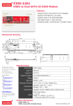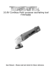
1
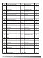
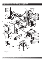
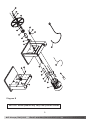
TBS250
250mm Bandsaw
With Stand
ACL Group (Intl) Ltd
Email: [email protected]
www.terratekintl.com
User Manual — Please read and retain for future reference
1
Contents
Parts List
Technical Information
Safety Instructions
Using Your Tool
Maintenance
Warranty
2
Parts List
NO.
Description
Quantity
NO.
Description
Quantity
1
Lower door
1
12
Ball bearing
4
2
Hex bolt
2
13
Upper wheel
1
3
Sleeve
2
14
Upper wheel shaft
1
4
Tooth washer
4
15
Open ring
2
5
Hex lock nut M6
6
16
Guard shaft
1
6
Hinge
4
17
Wheel shaft bracke
1
7
Upper door
1
18
Hexagon flange nut
8
8
Rivet
5
19
Guide plate
1
20
Carriage bolt
1
21
Brush
1
22
pacer tube
9
Bushing
2
10
Blade
1
11
Blade
2
1
1
ACL Group (Intl) Ltd
Email: [email protected]
www.terratekintl.com
23
Hexagon flange nut
1
43
Lower table trunnion
1
24
Column
1
44
L-ocking knob
2
25
Cap
1
45
Big flat washer
2
26
Tooth washer
2
46
Upper housing
1
27
Cross pan head screw
2
47
Screw
2
28
Switch plate
1
48
Hexagon bolt
2
29
Key Switch
1
49
Big flat washer
2
30
Pan screw M4×12
2
50
Board
1
31
Handle
2
51
Ball bearing
6
32
Hex srew
2
52
Connecting plate
1
33
Fastening shaft
1
53
Big semi-square bolt
4
34
Hexagon bolt M6×12
4
54
Lower housing
1
35
Flat washer
8
55
Dust chute
1
36
Hexagon bolt M8×45
1
56
Blade guide
1
37
ThuMb nut
1
57
Turn bolt
1
38
Flat washer
23
58
Blade guard
1
39
U bracket
1
59
Guiding board
1
40
Nut
1
60
Mitre guage
1
41
Guiding pin
1
61
Bar
1
42
Disc spring
16
62
Mitre gauge pointer
1
2
ACL Group (Intl) Ltd
Email: [email protected]
www.terratekintl.com
63
Cross pan head screw
1
83
Bearing bracket
1
64
Turn knob
1
84
Pan screw
2
65
Table insert
1
85
Upper guide seat
1
66
Table
1
86
Guide shagt
1
67
Fence guide extrusion
1
87
Pan bolt
2
68
Hex screw
1
88
Hex srew M8
1
69
Hexagon bolt M6×30
1
89
Tension setting knob
1
70
Hexagon bolt M8×16
4
90
Shaft
2
71
Big semi-square bolt
1
91
Gear spindle
1
72
Sliding bar
1
92
Motor cover
1
73
Trunion
1
93
Spring Washer
4
74
Locking knob
1
94
Bolt
4
75
Base
1
95
Lower bearing shaft
1
76
Rack
1
96
Hexagon bolt M6×20
4
77
Pan bolt
2
97
Strain relief
1
78
Ttop plate
1
98
Rip Fence
1
79
Bar
1
99
Cross pan head screw
3
80
Sliding plate
1
100
Lower wheel
1
81
Locking knob
5
101
Lower belt wheel
1
82
Wheel guide pin
6
102
Belt
1
3
ACL Group (Intl) Ltd
Email: [email protected]
www.terratekintl.com
103
Hex srew M14×1.5
1
112
Stand
4
104
Spring Washer
1
113
Short connecting plate
2
105
Key
1
114
Long connecting plate
2
106
Motor pulley
1
115
Rubber feet
4
107
Hexagon bolt
1
116
Bolt
16
108
Cord and plug
1
117
Hex srew
16
109
Motor plug
1
118
Work light
1
110
Capacitor
1
119
LED switch
1
111
Motor
1
4
ACL Group (Intl) Ltd
Email: [email protected]
www.terratekintl.com
Exploded Assembly Diagram
Diagram A
5
ACL Group (Intl) Ltd
Email: [email protected]
www.terratekintl.com
Diagram B
NOTICE: Actual product may vary from pictures shown.
6
ACL Group (Intl) Ltd
Email: [email protected]
www.terratekintl.com
B
A
C
D
E
G
H
F
A
A
Wheel cover knobs
B
Tension Control
C
LED light
D
Rip Fence
E
Miter gauge
F
Work table
G
LED switch
H
On/Off switch
7
ACL Group (Intl) Ltd
Email: [email protected]
www.terratekintl.com
3
dĞĐŚŶŝĐĂů/ŶĨŽƌŵĂƟŽŶ
250mm Bandsaw
Voltage:
230V ~ 50 Hz
Power:
S1 370 W
Ideal speed no:
1400 min-1
Blade length:
1712 mm
Max. blade width:
10 mm
Blade speed:
700 m/min
Cutting height:
100 mm / 90° , 55 mm / 45°
Throat width:
245 mm
Table size:
340 x 335 mm
Tilting range of table:
0° to 45°
Weight N.W./G.W.:
32/ 35 kg
Protection category:
Class I
IP degree:
IP40
Noise emission values
Sound and vibration values were measured in accordance with EN 61029.
Cutting
LpA sound pressure level 80.6 dB(A)
KpAuncertainty 3 dB
LWA sound power level 93.6 dB(A)
KWAuncertainty 3 dB
8
ACL Group (Intl) Ltd
Email: [email protected]
www.terratekintl.com
Wear ear-muffs.
The impact of noise can cause damage to hearing.
Keep the noise emissions and vibrations to a minimum.
- Only use appliances which are in perfect working order.
- Service and clean the appliance regularly.
- Adapt your working style to suit the appliance.
- Do not overload the appliance.
- Have the appliance serviced whenever necessary.
- Switch the appliance off when it is not in use.
Residual risks
Even if you use this electric power tool in accordance with instructions, certain residual risks
cannot be rules out. The following hazards may arise in connection with the equipment’s
construction and layout:
1. Lung damage if no suitable protective dust mask is used.
2. Damage to hearing if no suitable ear protection is used.
Read this entire manual before using this product.
Failure to do so can result in serious injury. Save this manual
for future reference.
Copyright© 2013 by ACL Group (Intl) Ltd. All rights reserved. This manual or any artwork
contained herein must not be reproduced in any shape or form without the express written
consent of ACL Group (Intl) Ltd. Diagrams within this manual may not be drawn
proportionally. Due to continuing improvements, actual product may differ slightly from the
product described herein.
9
ACL Group (Intl) Ltd
Email: [email protected]
www.terratekintl.com
Read and Keep This Manual
Please read carefully all instructions within this manual. Failure to follow all safety warnings can
result in serious personal injury. The term “Power Tool” in all of the following warnings refers to
your mains operated (corded) or battery operated (cordless) power tool
/ŵƉŽƌƚĂŶƚ^&dz/ŶĨŽƌŵĂƟŽŶ
This symbol is to warn you of potential personal injury
hazards. Please read carefully the notes along side this warning
to avoid possible injury or death.
General Safety Rules
WARNING!
Read all instructions. Failure to follow all instructions listed
below may result in electric shock, fire and/or serious injury. The term “power tool” in all
of the warnings listed refers to corded or cordless power tools.
Work area safety
Keep work area clean and well lit. Cluttered or dark areas invite accidents.
Do not operate power tools in explosive atmospheres, such as in the presence of flammable
liquids, gases or dust. Power tools create sparks which may ignite the dust or fumes.
Keep children and bystanders away while operating a power tool. Distractions can cause you
to lose control.
10
ACL Group (Intl) Ltd
Email: [email protected]
www.terratekintl.com
Electrical safety
Before use, ensure that the power outlet you are using matches the plug on your power tool
and that the voltage of the outlet matches that of your power tool.
Only use grounded extension cords with power tools fitted with proper plugs and if using
outdoors ensure any extension cord is suitable for outdoor use.
Always try to avoid body contact with grounded surfaces, such as radiators, cooking ranges
and any other fixed appliance with metal surfaces.
Do not expose your power tool to wet or damp conditions and NEVER use in rain.
Check regularly the power cord of your machine and any extension cord that you are using
for damage.
Do not carry or pull the machine with the power cord.
Ensure the cord is clear from hot surfaces, oil or sharp objects.
Personal safety
Never use your power tool whilst under the influence of alcohol, drugs or medication.
Tiredness can often cause accidents, stay alert.
Never use your power tool without the correct guards in place.
Always use ANSI approved eye protection and dust mask. Non slip safety shoes and hearing
protectors should be worn at all times when using your power tool.
Ensure any dust collecting device supplied with your power tool is connected correctly before
use.
Ensure all loose clothing, long hair or jewelry is kept clear of the power tool.
Before plugging your power tool into the power outlet ensure the power tool is in the OFF
position.
Check that wrenches or adjusting keys have been removed. Any wrench or key left attached
to a moving part can result in injury.
Power tool use and care.
Keep your power tool clean and well serviced at all times.
Never adjust or service any power tool before disconnecting from the mains electricity supply.
Always use the correct tool for the job.
Never force the tool to work harder than it is designed to do.
Never use your power tool with broken parts such as switches, guide fences or leg stands.
ALWAYS keep your power tools away from children.
Keep cutting tools sharp to ensure less stress on the motor.
Only have your power tool serviced by a qualified repair agent using manufacturers
recommended parts.
11
ACL Group (Intl) Ltd
Email: [email protected]
www.terratekintl.com
Service
Have your power tool serviced by a qualified repair person using only identical
replacement parts. This will ensure that the safety of the power tool is maintained.
Develop a periodic maintenance schedule for your tool. When cleaning a tool be careful
not to disassemble any portion of the tool since internal wires may be misplaced or
pinched or safety guard return springs may be improperly mounted. Certain cleaning
agents such as gasoline, carbon tetrachloride, ammonia, etc. may damage plastic parts.
When servicing a tool, use only identical replacement parts. Follow instructions in
the Maintenance section of this manual. Use of unauthorized parts or failure to follow
Maintenance Instructions may create a risk of electric shock or injury.
WARNING: For your own safety read Instruction Manual before operating your tool.
^ĂĨĞƚLJ/ŶƐƚƌƵĐƟŽŶƐ
MPORTANT!
4
Whenever you use electric tools it is imperative to take basic safety precautions
in order to reduce the risk of fire, electric shock and personal injury. Essential safety precautions
include:
1. Keep your work area tidy!
- An untidy work area invites accidents.
2. Check the working conditions!
- Do not expose electric tools to rain.
- Never use electric tools in damp or wet locations.
- Make sure there is good lighting.
- Do not use electric tools near flammable liquids or gases.
12
ACL Group (Intl) Ltd
Email: [email protected]
www.terratekintl.com
3. Guard against electric shock!
- Avoid body contact with earthed components.
4. Keep other persons away!
- Do not allow other persons, particularly children, to touch the tool or cable. Keep all persons
out of your work area.
5. Store tools in a safe place!
- When tools are not in use they should be stored in a dry, locked room out of children’s reach.
6. Do not overload your tools!
- Tools work better and safer when used within their quoted capacity range.
7. Use the right tool!
- Never use tools or attachments with insufficient power for the job in hand.
- Never use tools on jobs for which they were not intended. For example, do not use a hand-held
circular saw to cut down trees or lop off branches.
8. Wear suitable work clothes!
- Do not wear loose clothing or jewelry as they may get caught in moving parts.
- Non-slip shoes are recommended when working outdoors.
- Wear a hair net if you have long hair.
9. Use personal safety equipment!
- Wear safety goggles
- Use a dust mask when working on dusty jobs
10. Connect up a vacuum extraction system!
- If there are provisions for connecting up a vacuum extraction system, make sure that such a
system is fitted and in use.
11. Do not mis-use the cable!
- Do not carry the tool by its cable or pull on the cable to remove the plug from the socket-outlet.
Protect the cable from heat, oil and sharp edges.
12. Secure your workpiece!
- Use clamps or a vise to hold the workpiece securely. This is safer than using your hand and
will enable you to operate the machine with both hands.
13. Avoid abnormal working postures!
- Make sure you stand squarely and keep your balance at all times.
14. Look after your tools!
- Keep your tools sharp and clean for better and safer performance.
- Follow the instructions for maintenance work and for changing any attachments.
- Check the plug and cable regularly and, if damaged, have them replaced by an authorized
specialist.
13
ACL Group (Intl) Ltd
Email: [email protected]
www.terratekintl.com
Check the extension cable regularly and replace it if damaged.
Keep handles dry and free from oil and grease.
15. Always pull out the power plug:
When the tool is not being used, before carrying out any maintenance work and when changing
attachments such as blades, bits and cutters of any kind.
16. Remove adjusting keys and wrenches!
Make sure that all keys and adjusting wrenches are removed from the tool before switching it on.
17. Avoid unintentional starting!
Make sure that the switch is in OFF position when inserting the power plug.
18. When using an extension cable outdoors:
Check that it is approved for outdoor duty and is marked accordingly.
19. Be alert at all times!
Watch what you are doing. Use common sense.
Do not operate the tool if your mind is not on your work.
20. Check the tool for damage!
Each time before re-using the tool, carefully check that the guards or any slightly damaged
parts are working as intended.
Check that the moving parts are in good working order, that they do not jam, and that no
parts are damaged. Make sure that all parts are fitted correctly and that all other operating
conditions are properly fulfilled.
Unless otherwise stated in the operating instructions, damaged guards and parts have to be
repaired or replaced by an authorized service center.
Have damaged switches replaced by a customer service workshop.
Never use any tool if its switch cannot be turned off and on.
21. IMPORTANT!
The use of any accessory or attachment other than those recommended may involve a risk of
injury for you personally.
22. Have repairs carried out only by a qualified electrician!
This electric tool complies with the pertinent safety regulations. Repairs are to be carried out
only by a qualified electrician using original replacement parts or the user may suffer an
accident.
23. Wear safety gloves whenever you carry out any maintenance work on the blade!
24. In the case of mitre cuts when the table is tilted, the guide must be positioned on the lower
part of the table.
25. When cutting round wood, use a device to stop the workpiece from twisting.
26. When cutting boards in upright position, use a device to prevent kick-back.
14
ACL Group (Intl) Ltd
Email: [email protected]
www.terratekintl.com
27. A dust extraction system designed for an air velocity of 20 m/s should be connected in order
to comply with woodworking dust emission values and to ensure reliable operation.
28. Give these safety regulations to all persons who work on the machine.
29. Do not use this saw to cut fire wood.
30. The machine is equipped with a safety switch to prevent it being switched on again
accidentally after a power failure.
31. Before you use the machine for the first time, check that the voltage marked on the rating
plate is the same as your mains voltage.
32. If you use a cable reel, the complete cable has to be pulled off the reel.
33. Persons working on the machine should not be distracted.
34. Note the direction of rotation of the motor and blade.
35. Never dismantle the machine’s safety devices or put them out of operation.
36. Never cut workpieces which are too small to hold securely in your hand.
37. Never remove loose splinters, chips or jammed pieces of wood when the saw blade is running.
38. It is imperative to observe the accident prevention regulations in force in your area as well
as all other generally recognized rules of safety.
39. Note the information published by your professional associations.
40. Position the blade guard so it is approx. 3 mm above the material you want to saw.
41. Important! Support long workpieces (e.g. with a roller table) to prevent them sagging at the
end of a cut.
42. Make sure the blade guard (10) is in its lower position when the saw is being transported.
43. Safety guards are not to be used to move or misuse the machine.
44. Blades that are misshapen or damaged in any way must not be used.
45. If the table insert is worn, replace it.
46. Never operate the machine if either the door protecting the blade or the detachable safety
device is open.
47. Ensure that the choice of blade and the selected speed are suitable for the material to be cut.
48. Do not begin cleaning the blade until it has come to a complete standstill.
49. In the case of straight sawing against the parallel stop, a push stick must be used.
50. The bandsaw blade guard should be in its lowest position close to the bench during transport.
51. For mitre cuts when the table is tilted, the parallel stop must be positioned on the lower part
of the table.
52. When cutting round timber, use a suitable holding device to prevent the workpiece turning.
53. Never use guards to lift or transport items.
54. Ensure that the bandsaw blade guards are used and correctly adjusted.
55. Keep your hands a safety distance away from the bandsaw blade. Use a push stick for
narrow cuts.
15
ACL Group (Intl) Ltd
Email: [email protected]
www.terratekintl.com
Only use qualified repair agents to service this power tool.
Only use qualified electrician to repair any damaged wiring.
NEVER remove the grounding prong from the power tool or extension cord.
Symbols
IMPORTANT: Some of the following symbols may be used on your tool.
V…………………………volts
A…………………………amperes
Hz……………………….hertz
~…………………….….alternating current
…/m……………….....revolutions per minute
.....................class II construction (double insulated)
Kg………………………..kilograms
n0………………………..No load speed
……………….….....Conforms to European Harmonised New Approach Directives
DC ………………..…….Direct Current
Special safety instructions
1. DO NOT OPERATE WITH DULL OR WORN BLADES. Dull blades require more effort to use and
are difficult to control. Inspect blades before each use.
2. NEVER POSITION HANDS OR FINGERS IN LINE WITH THE CUT.
Serious personal injury could occur.
3. DO NOT OPERATE THIS BANDSAW WITHOUT WHEEL, PULLEY, AND BLADE GUARDS IN PLACE.
4. WHEN REPLACING BLADES, make sure teeth face down, towards the table. The force of the
cut is always down. Make sure the blade is properly tensioned.
5. CUTS SHOULD ALWAYS BE FULLY SUPPORTED by the table or some type of support fixture.
Always support round stock in a V-block.
6. DO NOT BACK WORKPIECE AWAY from the blade while the saw is running. Plan your cuts so
you always cut out of the wood. if you need to back the work out, turn the bandsaw off and
wait for the blade to come to a complete stop. Do not twist or put excessive stress on the
blade while backing work away.
7. ALWAYS FEED STOCK EVENLY AND SMOOTHLY. Let the blade cut at its own pace. Do not
force or twist blade while cutting, especially when sawing small radii.
8. THIS MACHINE IS NOT DESIGNED TO CUT METAL or other materials, only wood.
16
ACL Group (Intl) Ltd
Email: [email protected]
www.terratekintl.com
9. MAKE SURE BLADE IS RUNNING AT FULL SPEED before beginning a cut.
10. DO NOT MANUALLY STOP OR SLOW THE BLADE after turning the saw off. Allow it to come
to a complete stop before you leave it unattended.
11. ALL INSPECTIONS, ADJUSTMENTS, AND MAINTENANCE MUST TO BE DONE WITH THE
POWER OFF and the plug pulled from the outlet. Wait for all moving parts to come to a
complete stop.
12. IF AT ANY TIME YOU ARE EXPERIENCING DIFFICULTIES PERFORMING THE INTENDED
OPERATION, stop using the machine! Then contact our service department or ask a qualified
person how the operation should be performed.
Unpacking
Carefully remove the product and any accessories from the box. Make sure that all items listed
in the packing list are included.
In The Box
A) Bandsaw
B) Table
C) Rip Fence
D) Mitre Gauge
E) 1712mm*10mm Blade(TPI:6)
F) Steal Stand
G) User manual
5
Using Your Tool
Functional Description
WARNING:Disconnect the plug from the power source before making any assembly,
adjustments or changing accessories. Such preventive safety measures reduce the risk of
starting the tool accidentally.
Assembly
WARNING:Disconnect the plug from the power source before making any assembly,
adjustments or changing accessories.
17
ACL Group (Intl) Ltd
Email: [email protected]
www.terratekintl.com
Stand (Fig. B)
1. Place the bandsaw (A) on its back as shown in Fig. B.
2. Assemble four legs (B) to the inside of the base of the bandsaw, securing each leg with two
ea. carriage bolts (C), flat washers (D) and hex nuts (E). Hand tighten only at this time.
3. Attach a long plate (F) to the rear legs as shown in Fig. B. Secure with 2 ea. carriage bolts
(G), flat washers (H), and hex nuts (I). Hand-tighten only at this time.
4. Repeat above for long plate to the front legs in the same manner described above,
hand-tightening only.
5. Attach two short plates (J) to the right legs and left legs in the same manner. Secure each
leg with 2 ea carriage bolts (K), flat washers (L), and hex nuts (M). Hand-tighten only at this
time.
6. Slip rubber feet onto the ends of the stand legs.
7. Place the saw and stand upright on a level surface. Make sure that all four legs are flat on,
the surface.
8. Tighten all nuts securely.
Fig.B
Table
1) Place table onto the trunnion (Fig. 1) by allowing the saw blade to pass through the slot on
the table.
2) Line up four threaded mounting holes underneath the table (D) with the four mounting
through-holes on the trunnion.
3) Install to the trunnion with four hex screws (M6x16) and lock washers and tighten.
18
ACL Group (Intl) Ltd
Email: [email protected]
www.terratekintl.com
Fig.1
90° Table Stop
Fig.2
(Fig. 2)
1) Loosen the locking knob and tilt the table up. (A)
2) Thread the M6 nut about half way onto the M6x32 screw (B). Then thread the screw (D)
about half way into the mounting hole (E) underneath the table. Final adjustment to be done
later.
Rip Fence Guide (Fig. 1)
Attach rip fence guide to table with four thumb screws (E).
Table Insert
Place table insert onto center hole in table.
Adjustments
Tilting the Table (Fig. 2)
1) Loosen the lock knob (A).
2) Tilt table (B) up to 50 degrees maximum to the right or down 5 degrees to the left. The angle
can be read on the scale (F) on the trunnion bracket.
Note: When the table is perpendicular (90º) to the blade the scale indicator will read 0º.
3) Tighten the lock knob (A).
19
ACL Group (Intl) Ltd
Email: [email protected]
www.terratekintl.com
90º Table Stop Adjustment (Fig. 4)
Adjusting the table stop
The table stop (E) is typically set at 90º (perpendicular) with the blade.
1) Loosen lock knob (A) then tilt the table (B) down, bringing it to rest against the table stop (E).
2) Place a square on the table and against the blade to see if the table is 90º to the blade.
3) If an adjustment is necessary, tilt the table up to access the table stop (E).
4) Loosen the lock nut (C) and turn the table stop (E) in or out to raise or lower the stop.
Tighten the lock nut to hold the table stop in place.
5) Bring the table back to level, let it rest against the stop and confirm table is 90º with the
blade as described in step 3.
Fig.3
Fig.4
Adjusting the table tilt indicator
1) Set the table at 90º with the blade as described above.
2) Confirm that the table tilt indicator (F) in (Fig. 4) points to zero.
,IÛDGMXVWPHQWLVUHTXLUHG6OLJKWO\ORRVHQWKHVFUHZWKDWLVVHFXULQJWKHLQGLFDWRUDGMXVW
indicator to point to zero; then re-tighten the screw.
Changing Blades
(Fig. 5)
WARNING: Blade teeth are sharp! Use care when handling the saw blade. Failure to comply
may cause serious injury.
1) Disconnect machine from power source.
2) Open both wheel covers (A).
3) Remove rip fence guide (E-Fig. 1).
4) Release tension on the blade by loosening the tension handle (A-Fig.6).
5) Remove blade (C) from upper and lower wheels (D,E) and from between the upper and lower
blade guides (F,G).
20
ACL Group (Intl) Ltd
Email: [email protected]
www.terratekintl.com
6) Remove the blade through the slot (H) in the table.
7) Guide the new blade through table slot (H), smooth edge first. Place it around the upper and
lower wheels (D,E) and into the upper and lower blade guides (F,G).
Note: The blade teeth should face the front of the machine, and they should point down
toward the table.
8) Position the blade to track in the middle of the rubber tires on the wheels (D,E).
9) Put tension on the blade by tightening the handle (A-Fig. 6).
10) Replace rip fence guide (E-Fig. 1).
Before operating the saw, check that the blade is tracking and has proper tension.
Fig.6
Fig.5
Adjusting Blade Tension
1) Disconnect machine from power source.
The blade tension knob (A-Fig.6)) is used to adjust blade tension.
Note: All bearings on upper and lower guides must be clear of blade.
2) Apply just enough tension to take the slack out of the blade.
3) Turn one wheel a few times to allow the blade to position itself in the center of the tire.
Note: If blade does not center see Adjusting Blade Tracking section (this page).
A scale (D) directly behind the upper wheel (E) indicates the approximate tension according
to the width of the blade.
4) Set the blade tension with knob (A) to correspond to the blade width as marked on the
gauge (D).
Note 1: Changes in blade width and the type of material being cut will have an effect on blade
tension.
Note 2: Keep in mind that too little or too much blade tension can cause blade breakage.
21
ACL Group (Intl) Ltd
Email: [email protected]
www.terratekintl.com
Adjusting Blade Tracking
Tracking refers to how the blade is positioned on the wheels while in motion. The blade should
trackin the center of both wheels.
The blade must be slightly tensioned before adjusting blade tracking. Make sure blade guides
and bearings do not interfere with the blade. If blade tracking is required, blade guide adjustment
is described on the following page.
1) Open the top and bottom wheel covers. Rotate the wheel forward by hand, and observe the
position of the blade. It should be in the center of the wheel.
If adjustment is necessary:
2) Loosen the wing nut (B-Fig.7) and make adjustment with tracking knob (A) while rotating
wheel by hand.
3) Tightening the tracking knob slightly will move the blade so it tracks towards the rear of
machine. Loosening the tracking knob slightly will cause the blade to track toward the front
of the machine.
4) After blade is tracking in the center of the wheel, tighten the wing nut (B).
Fig.7
Fig.8
Upper Blade Guide Positioning
(Fig. 8)
The upper blade guide assembly (A) should be adjusted to just above the material being cut.
To adjust: Turn knob (B) and raise or lower the upper blade guide assembly (A).
22
ACL Group (Intl) Ltd
Email: [email protected]
www.terratekintl.com
Blade Guide Adjustment(Fig. 9)
The blade guide assembly consists of two roller guides (bearings) positioned on each side of the
blade to provide blade stability. A third guide (thrust bearing) is positioned behind the blade to
provide blade support. There are two blade guide assemblies – an upper assembly and lower
assembly.
Adjustments are performed in the same manner for each assembly. Follow procedures outlined
below.
Thrust Bearing Adjustment ( Fig. 10 and Fig. 11)
Disconnect machine from the power source! Never make adjustments with the machine running!
Failure to comply may cause serious injury!
Note: Blade must already be tensioned and tracking properly.
1) For the upper thrust bearing, loosen thumbscrew (A). For the lower blade guide, loosen set
screw (B) with the 3mm hex wrench provided.
2) Slide the adjustment shaft (D) so the blade is positioned in the middle of the thrust
bearing (C).
The thrust bearing (C) is mounted on a concentric shaft (D). When the shaft is rotated, the
relative position of the bearing to the back of the blade can be changed.
3) Rotate the adjustment shaft (D) so the thrust bearing (B) just clears the back of the saw
blade.
4) Tighten thumbscrew(A) and setscrew (B). If a blade is being replaced with a new one of a
different size, the adjustment described above may fall out of range and further adjustment
may be required as follows:(Fig. 11)
Loosen the hex cap screw (E, not visible) with a 10mm wrench and adjust the entire assembly
back or forth to just clear the back of the saw blade. Tighten cap screw (E), then fine tune the
adjustment by repeating the first part of this step.
Fig.9
Fig.10
23
ACL Group (Intl) Ltd
Email: [email protected]
www.terratekintl.com
Guide Bearing Adjustment(Fig.11)
Disconnect machine from the power source! Never make adjustments with the machine running!
Failure to comply may cause serious injury!
Note: Blade must already be tensioned and tracking properly.
1) For the upper blade guide, loosen two thumbscrews (F). For the lower blade guide, loosen
two setscrews (G) with the 3mm hex wrench provided.
3) Slide the adjustment shaft (H) to position each roller guide (I) approximately 1/16" behind the
gullets (teeth) of the saw blade. The roller guide (I) is mounted on a concentric shaft (H).
When the shaft is rotated, the relative position of the guide to the blade can be changed.
3) Rotate each adjustment shaft (H) to position the guides (I) within 1/32" of the saw blade.
5) Secure the roller guides (I) by tightening thumbscrews (F, upper guide) or setscrews
(G, lower guide).
Fig.12
Fig.11
Replacing the Poly V-Belt
(Fig.12)
Disconnect machine from the power source! Never make adjustments with the machine running!
Failure to comply may cause serious injury!
1) Open the upper and lower wheel cover doors.
2) Remove the saw blade.
3) Remove tension on the drive belt (A) by loosening the hex screw (13mm wrench required)
on the back of the cabinet that secures the motor.
4) Using snap ring pliers, remove the snap ring (B) that secures the lower wheel (C) to the
shaft (D).
5) Slide the lower wheel assembly off the shaft (D) which will dislodge the belt (A), discard the
old belt.
6) Place the new belt onto the lower wheel pulley.
7) Reinstall lower wheel assembly by sliding it back onto the shaft (D).
8) Replace snap ring (B).
24
ACL Group (Intl) Ltd
Email: [email protected]
www.terratekintl.com
9) Place the new belt (A) partially around the motor pulley (E) to get it started, then turn the
wheel (C) by hand until the belt (A) is completely seated on the motor pulley (E).
10) Push the motor down to add tension to the belt (A).
The belt is properly tensioned when moderate finger pressure on the belt between the two
pulleys causes about 1/2" deflection.
11) Tighten the hex cap screw on the back of the cabinet that secures the motor.
Re-install the blade.
Adjusting Poly V-Belt Tension
Disconnect machine from the power source! Never make adjustments with the machine running!
Failure to comply may cause serious injury!
1) With a 13mm wrench, loosen the hex screw on the back of the cabinet that secures the motor.
2) Push the motor down to add tension to the belt (C).
The belt is properly tensioned when moderate finger pressure on the belt between the two
pulleys causes a 1/2" deflection.
3) Tighten the hex screw that secures the motor.
Operation
On/Off Switch
Ensure that the switch is in the “OFF” position. If the plug is connected to a receptacle while
the switch is in the “ON” position, the power tool will start operating immediately and can cause
serious injury.
On/Off Switch – located on front of machine: pull switch out to start; push switch in to stop.
Whenyellow safety key is removed, machine will not start.
Work Lamp Switch – located on front of machine above On/Off switch. Turns LED work lamp on
and off.
Making cuts
1) Adjust the bevel angle, rip fence, mitre gauge and upper blade guide.
2) Make sure the table insert is in place and flush with the table.
3) Start the saw by pulling switch out to start.
4) Start the cut by pushing the wood into the moving saw blade.
5) Do not force the cut, use only enough pressure to keep the saw cutting, let the blade do the
work.
6) If cutting round material use a jig or fixture to keep the material from turning.
7) When you are finished remove the yellow safety key to prevent unauthorized use.
25
ACL Group (Intl) Ltd
Email: [email protected]
www.terratekintl.com
6
Maintenance
WARNING: For your own safety, make sure switch is off and unplugged from the power source
before doing any maintenance or adjustments. Replace the power cord immediately if it is cut,
worn, or damaged in any way.
Accessories
CAUTION: Use only accessories or attachments recommended for use with your Terratek tool
specified in this manual. The use of any other accessories or attachments might present a risk
of injury to persons. Only use accessory or attachment for its stated purpose.
General Maintenance
1. Keep the air vents free from obstruction and clean regularly.
2. Check regularly for any dust particles entering the grills around the motor and the switch.
Use a soft brush to remove any dust particles. Wear safety glasses to protect your eyes
whilst cleaning.
3. Monitor the dust bag (if equipped) and empty when approximately half full. Always empty
into an appropriate container. REMEMBER: dust can be hot and cause fire.
4. If the cutting tool has become dull, replace it. Dull cutters will cause increased tear-out and
ragged edges on the cuts.
5. Lubricate all moving parts at regular intervals.
6. To clean the body of the power tool, only use a soft damp cloth. Do NOT immerse in water.
A mild detergent can be used but NOT petrol or any alcohol based product.
7. Should the power cord become damaged only allow a fully qualified electrician to replace
or repair.
Disposal
Power tools, accessories and packaging should be sorted for environmentally-friendly recycling.
Only for EC countries:
Do not dispose of power tools into household waste!
According to the European Directive 2002/96/EC on waste electrical and
electronic equipment and its incorporation into national right, products
that are no longer suitable for use must beseparately collected and sent
for recovery in an environmentally-friendly manner.
26
ACL Group (Intl) Ltd
Email: [email protected]
www.terratekintl.com
ĞĐůĂƌĂƟŽŶŽĨŽŶĨŽƌŵŝƚLJ
We ACL Group (Intl.) Ltd, England DN6 8LZ declare that the Bandsaw has been manufactured
according to our full quality assurance procedures.
The declaration is to certify that it conforms to CE, EMC, MD, LVD and RoHS directives:
EN55014-1:2006+A1
EN55014-2:1997/ +A1:2001/ +A2: 2008
EN61000-3-2: 2006 + A1 + A2
EN61000-3-3: 2008
All provisions of Annex 1 of Council Directive 2004/108/EC – EMC directive
EN61029-1: 2009
EN61029-2-5: 2002
All provisions of Annex 1 of Council Directive 2006/42/EC – the Machinery Directive
2006/95/EC - the Low Voltage Directive
RoHs 2011/65/EU
2011/65/EU
Mr. Alan Garnett, UK QA Manager
Environmental Protection
RECYCLING: WASTE ELECTRICAL PRODUCTS SHOULD NOT BE DISPOSED OF WITH
HOUSEHOLD WASTE. PLEASE RECYCLE WHERE FACILITIES EXIST. CHECK WITH YOUR LOCAL
AUTHORITY OR RETAILER FOR RECYCLING ADVICE.
27
ACL Group (Intl) Ltd
Email: [email protected]
www.terratekintl.com
7
Warranty
Please read the following carefully
ACL Group (Intl) Ltd. and/or it’s distributor has provided the parts list and assembly diagram
as a reference tool only. Neither ACL Group (Intl). Ltd. or its distributor makes any
representation or warranty of any kind to the buyer that he or she is qualified to do any repairs
or replace any parts of this product. ACL Group (Intl) Ltd. and its distributor expressly state
that all repairs or parts replacement should be done by certified or licensed technicians. The
buyer assumes all risk and liability arising out of his or her repairs or parts replacement to
the original product.
12 Months Limited Warranty
If within 12 months from the date of purchase you experience any problems with your product,
please return the product to its distributor/dealer for repair or replacement. This warranty
DOES NOT COVER normal wear, or any damage as a result of accidents, misuse, abuse or
negligence.
28
ACL Group (Intl) Ltd
Email: [email protected]
www.terratekintl.com
ACL Group (Intl) Ltd
Email: [email protected]
www.terratekintl.com