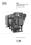
1
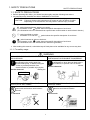
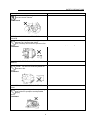
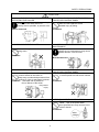
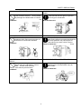
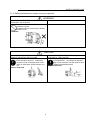
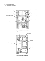
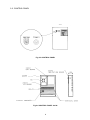
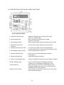
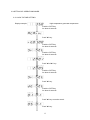
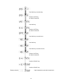
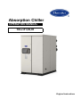
Absorption Chiller OPERATION MANUAL 16LJ-01,02,03 Original instructions Notes to Users Thank you for purchasing Carrire Absorption Chiller. Before operating the Chiller, please read this manual thoroughly. It contains instruction for the operation and maintenance of the Chiller. Please utilize the Chiller to its optimum performance by following recommended daily maintenance and handling, and periodic service. If you need any information about maintenance contract or any other inquiries, please contact Carrier service agent. Product Information If you have problems of questions concerning your chiller, you will need the following information. Model and serial numbers are on the nameplate on the bottom of the control panel. Model No. Serial number DECLARATION OF CONFORMITY This product is marked " CE " as it satisfied EEC Directive No. 2006/42/EC, 2004/108/EC, 97/23/EC, 90/396/EEC and conforms with following standards. This declaration will become void in case of misusage and/or from non observance though partial of Manufacturer's installation and/or operating instructions. Note: The contents of this manual are subject to change without notice. 814-6-0510-121-01-0 Absorption Chiller Operation Manual < Hot Water Fired type> Table of Contents 0. SUMMARIES OF PRODUCT CHARACTERISTICS ………………………………………0 1. SAFETY PRECAUTIONS 1-1. SAFETY PRECAUTIONS 1-2. HIGH TEMPERATURE・HIGH VOLTAGE CAUTION 1-3. USE ENVIRONMENT 1-4. WATER TREATMENT …………………………………………1 …………………………………………1 …………………………………………7 …………………………………………7 …………………………………………7 2. ILLUSTRATION 2-1. DETAIL OF CHILLER 2-2. CONTROL PANEL 2-3. FLOWCHART OF CHILLER AND FUNCTION OF EACH SECTION …………………………………………8 …………………………………………8 …………………………………………9 …………………………………………12 3. OPERATING INSTRUCTIONS 3-1. SELF-DIAGNOSTIC FUNCTION 3-2. DESCRIPTION OF KEYS AND THEIR FUNCTIONS 3-3. SETTING OF OPERATION BOARD 3-4. COOLING OPERATION 3-5. HOW TO CHANGE INDICATION ON DATA DISPLAY 3-6. HOW TO CHANGE INDICATION AND SETTING POINT 3-7. MAINTENANCE MESSAGE 3-8. ALARM INDICATIONS AND ACTIONS …………………………………………15 …………………………………………15 …………………………………………16 …………………………………………17 …………………………………………23 …………………………………………26 …………………………………………28 …………………………………………29 …………………………………………31 4. MAINTENANCE 4-1. DAILY MAINTENANCE 4-2. PERIODIC MAINTENANCE 4-3. WATER TREATMENT 4-4. RECOMMENDED SCHEDULE OF MAINTENANCE AND REPLACEMENT OF MAIN COMPONENTS …………………………………………40 …………………………………………40 …………………………………………43 …………………………………………46 5. MAINTENANCE CONTRACT 5-1. ANNUAL MAINTENANCE CONTRACT 5-2. INSPECTION REPORT 5-3. WARRANTY …………………………………………51 …………………………………………51 …………………………………………51 …………………………………………52 …………………………………………50 0. Summaries of product characteristics 0-1. Product explanation (1) Excellent for peak shaving during high electrical demand periods. (2) Designed to provide chilled water from waste heat sources, generated from industrial processes and cogeneration systems. (3) Allows diversification of critical cooling requirements. Critical cooling loads are met with minimal electrical power input with a hot water-fired chiller. (4) Allows for smaller generator set installation be utilized since the electrical load associated with an absorption chiller is minimal when compared to an electric chiller. (5) Ozone safe, CFC free. Cooling requirements are met without chlorine based refrigerants. (6) Reduces affectors to global warming. Minimizes global impact by greatly reducing electricity consumption and eliminating the use of greenhouse gases. (7) Environment: Molybdate solution inhibitor is used with no impact on environment. (8) Low noise and vibration. The absorption chiller doses not utilize a large motor-compressor, and this leads to quiet, trouble-free operation. (9) Small footprint saves facility space. 0-2. Use of product Absorption Chiller is air conditioning equipment achieving comfortable space, energy saving, and economic efficiency. It has been used in office buildings, hotels, department stores, hospitals, schools, convention centers, government building, etc. 0-3. Business name and address (1) Manufacturer Business name : Panasonic Corporation Address : 1-1-1 Sakata, Oizumi-machi,, Ora-gun,,Gunma 370-0596,Japan (2) Importer Business name: Carrier S.A.S Address : BP 49-Route de Thil Q1122 MONTLUEL Cedex , France 0-4. Noise data Model : 16LJNoise [dB(A)] 01 02 03 Less than 70 0 1. SAFETY PRECAUTIONS SAFETY PRECAUTIONS 1-1. SAFETY PRECAUTIONS * Before operating this chiller, you should first thoroughly read the following instructions. * All precautions are classified into either WARNING or CAUTION. WARNING: Failure to observe this instruction may result in serious injury or death. CAUTION : Failure to observe this instruction may cause an injury or failure of chiller. Depending on circumstances, this may result in serious injury or death. < Example > symbol denotes danger, warning or caution. The illustration in the symbol shows the specific description of such item. (The illustration to the left indicates that a special care must be taken to avoid electric shocks.) symbol prohibits an action. The illustration in or near the symbol shows the specific description of such item. symbol instructs an action to be done. The illustration in the symbol shows the specific description of such item. (The illustration to the left indicates that it should be grounded.) * After reading this manual, it should be kept in fixed place to be available for any user at any time. 1-1-1. For safety usage WARNING TURN OFF THE BREAKER BEFORE CLEANING STOP THE OPERATION IN CASE OF A FIRE, AND CHECKING EARTHQUAKE OR POSSIBLE THUNDERBOLT Stop the operation in case of a fire or Always turn off the breaker before cleaning earthquake or when there is likely to be a and checking the cooling tower fan, thunderbolt, to prevent a fire or electric chilled water pump, or others linking the shocks. chiller, to provide protection from Must be observed electric shocks or possible injury by the Must be observed rotating fan. INSPECTION DO NOT TOUCH THE CONTROL PANEL SWITCH WITH WET HANDS Do not touch the switch inside the control panel with wet hands to avoid electric shocks. DO NOT TOUCH THE WIRINGS INSIDE THE CONTROL PANEL Do not touch the wirings inside the control panel to avoid electric shocks. Do not touch Do not touch SWITCH OFF ON 1 SAFETY PRECAUTIONS DO NOT TOUCH HIGH VOLTAGE LEAD WIRE Do not touch high voltage lead wire to prevent electric shocks. Do not touch KEEP FLAMMABLES AWAY FROM THE CHILLER Do not place any flammables (gasoline, thinner, etc.) close to the chiller, flue, chimney and oil tank to prevent a fire. Prohibited DO NOT OPERATE THE CHILLER WHEN GAS SMELLS Do not operate the chiller when gas smells. Do not turn on/off any switch to prevent a fire. Prohibited DO NOT TOUCH ANY ROTATING PART OF FANS Keep away your fingers from any rotating part of fans or pumps to avoid possible injury. Prohibited 2 SAFETY PRECAUTIONS CAUTION SOLVE ALL THE PROBLEMS BEFORE DO NOT PLACE HEAVY OBJECTS ON THE RESTARTING THE CHILLER CHILLER OR CONTROL PANEL Solve all the problems before restarting the Do not place heavy objects on the chiller when the safety device or chiller or control panel to avoid security device operates, to prevent a fire. possible injury by falling. Must be observed Prohibited DO NOT CLIMB UP THE CHILLER CALL SPECIALISTS FOR SERVICE OR MAINTENANCE Call specialists for service or maintenance. Wrong service /maintenance may cause electric shocks, a fire or burns. Do not climb up the chiller/heater to avoid falling down. Prohibited Must be observed AUTHORIZED PERSONNEL ONLY A notice, “For Authorized Personnel Only” must be affixed to the chiller to keep away unauthorized personnel from touching it. If this is anticipated, enclose Prohibited the chiller with a protective fence. Misuse of the chiller may cause injury. DO NOT POUR WATER OVER THE CHILLER OR CONTROL PANEL Do not pour water over the chiller or control panel to avoid electric shocks. Prohibited USE THE CORRECT POWER SUPPLY This is indicated on the name plate of the chiller. Use of the power other than specified here may cause a fire or electric shocks. Prohibited What voltage? 3 SAFETY PRECAUTIONS NEVER CHANGE THE SET VALUE STOP THE OPERATION WHEN BLACK SMOKE RISES Stop the operation when black smoke rises and call service agent, to prevent a fire by poor combustion. Never change the set value of the safety and/or protective devices. Wrong setting may damage the chiller/heater or cause a fire. Prohibited Must be observed OBSERVE THE SPECIFIED PRESSURE OF WATER DO NOT TOUCH THE ABSORBENT Do not touch the spare or leaked absorbent which may cause corrosion of metal areas or cause skin diseases. The specified pressure of chilled/hot water and cooling water must strictly be observed. Incorrect pressure may cause spout or leak which may cause a short circuit or Must be observed burns. Prohibited DO NOT TOUCH THE HIGH TEMPERATURE AREAS Do not touch the high temperature areas. These areas are indicated by caution label. Please avoid touching such areas to prevent burns. Prohibited STOP THE PURGE PUMP TO REPLACE OIL Please stop the purge pump when replacing oil to avoid possible injury by fuel scatter. Must be observed STOP 4 SAFETY PRECAUTIONS 1-1-2. Safety precautions for repair, moving or rejection WARNING ONLY AUTHORIZED PERSONNEL SHOULD OVERHAUL THE CHILLER Only those who are authorized should overhaul the chiller. Incomplete service could result in electric shocks or a fire. Prohibited CAUTION ONLY AUTHORIZED PERSONNEL SHOULD REMOVE OR REPAIR THE CHILLER Any relocation or moving of the chiller should be done by authorized personnel only. Incomplete work could result in water leak, electric shocks or a fire. Must be observed ONLY AUTHORIZED PERSONNEL SHOULD DISPOSE OF THE CHILLER To dispose of the chiller, contact the local specialists. Any defective disposal may cause corrosion of metal areas or skin diseases by absorbent leak. Must be observed 5 SAFETY PRECAUTIONS 1-1-3.Operating precautions ① Keep the purge valve shut tightly to prevent air from leaking into the Chiller, which may cause the failure of the Chiller. ② Keep to turn on the power supply to the control panel without maintenance service. ③ During the dilution cycle operation of the Chiller as well, the chilled water pump (both the primary side and the secondary side) and air handling unit must be operated for the necessary time. The Chiller has a little cooling capacity even if it is in the dilution cycle operation. Do not stop the air handling unit before the necessary time to prevent possible subcooling. ④ Do not perform an insulation test on the control circuits of the electric controller. ⑤ Use Carries recommended interlock system for stop/start of the auxiliary equipment. The interlock system automatically stops/starts chilled water pump and cooling water pump. Please follow the start procedure in Figure 1-1 below. Start Procedure ① Chilled water pump ③ → Cooling tower ② → Cooling water pump ④ → Absorption Chiller ↓ ⑤ Air handling unit Stop Procedure ① Absorption Chiller ② → Cooling water pump ③ → Cooling tower ④ → Chilled water pump ↓ ⑤ Air handling unit Fig.1-1 Auxiliary Equipment Start/Stop Sequence 6 1-2. HIGH TEMPERATURE・HIGH VOLTAGE CAUTION 1-2-1.Do not touch the Chiller during operation since the surface of it reaches a high temperature. 1-2-2. Do not touch the absorbent pump, the refrigerant pump, the purge pump during operation, since they reach a high temperature. 1-2-3. Do not touch the junction box during operation, since it contains high pressure wiring. 1-2-4. Do not touch the terminal box during operation, since it contains high voltage wiring. 1-3. USE ENVIRONMENT 1-3-1. Machine room Absorption Chiller is indoor use ONLY. IP number of Absorption Chiller is IP40. Please keep the machine room temperature between 5℃ and 40℃ for protection of the solution crystallization during chiller shut down. Please keep the humidity in the machine room within 90%. 1-3-2. Field wiring For CE, please connect to power source by overvoltage category Ⅲ, and to other wiring by overvoltage category Ⅱ. 1-3-3. Altitude Please install Absorption Chiller at a height of less than 1000m above sea level. If the location is higher than 1000m above sea level, please contact Carrier agent. 1-4. WATER TREATMENT Refer to "4. Maintenance" section. 7 2. ILLUSTRATION 2-1. DETAIL OF CHILLER Cooling water inlet Hot water outlet Rupture disc Hot water inlet Cooling water outlet Chilled water outlet Chilled water inlet Evaporator Fig.2-1 WATER CONNECT SIDE Generator Condenser Absorber Control panel Power box Fig.2-2 CONTROL PANEL SIDE 8 2-2. CONTROL PANEL Fig.2-3 CONTROL PANEL Fig.2-4 CONTROL PANEL inside 9 Fig.2-5 POWER BOX TERMINAL BASE MAGNET SWITCH & OVERCURRENT RELAY CIRCUIT BREAKER Fig.2-6 POWER BOX inside 10 Fig.2-7 OPERATION BOARD 11 2-3. FLOWCHART OF CHILLER AND FUNCTION OF EACH SECTION a) EVAPORATOR The refrigerant is dispersed on the heat transfer tubes of evaporator. Chilled water through the heat transfer tubes of evaporator is cooled by the latent heat of vaporized refrigerant. b) ABSORBER The concentrated solution is dispersed on the heat transfer tubes of absorber. The refrigerant vapor from evaporator is absorbed on the heat transfer tubes of absorber by the concentrated solution. Cooling water through the heat transfer tubes of absorber is heated by absorption heat. c) HEAT EXCHANGER The diluted solution, after leaving the absorber section, passes through the heat exchanger, where it is heated by the concentrated solution. The concentrated solutions are cooled by the diluted solution. This cooling process of the concentrated solution allows for greater absorbing power due to its lower temperature. d) GENERATOR The passes through the heat transfer tubes of generator. The diluted solution in the generator is heated by the hot water. It releases the refrigerant vapor and is concentrated. It becomes concentrated solution. e) CONDENSER The refrigerant vapor from the generator is condensed on the heat transfer tubes of condenser. Cooling water from the absorber is heated by condensation heat. f) PURGE UNIT Gather the non-condensable gas within the Chiller/heater and store it in the purge tank. 12 Table 2-1 Sensor NAME SYMBOL DT1 Chilled water outlet temperature DT2 Cooling water outlet temperature DT3 Generator temperature DT5 Condenser temperature DT6 Chilled water inlet temperature DT7 Cooling water inlet temperature DT8 No use DT9 No use DT10 Diluted solution temperature at Absorber outlet DT11 Refrigerant temperature at Evaporator DT12 Cooling water mid temperature DT13 No use DT14 No use DT15 Driving hot water inlet temperature DT16 Driving hot water outlet temperature 23CH Temperature controller 69CH Chilled water flow switch PCH Palladium cell heater 69PR Purge tank pressure 13 Fig.2-8 FLOW DIAGRAM 14 3. OPERATING INSTRUCTIONS 3-1. SELF-DIAGNOSTIC FUNCTION Self-diagnostic function starts when the breaker inside the control panel of the Chiller is turned on. After self-diagnosis is completed, the data display on the operation board shows the following indication. 3-1-1. Action after power supply throwing in and an indication Throw a power supply into and (turn on a breaker in a control panel and) when it dose, a self-diagnostic function acts as follows. (1) Data display (the 7 segment LED) and all LEDs light up. (2) The data display shows a version number when there is no abnormality. When there is a power failure, H-10 is displayed after power return. NOTE : The version number differs according to an each Chiiler type. (3) The data display shows the generator temperature. (120.4) If self-diagnosis function detects any failure, it will be shown on the data display. As for the alarm indication, please refer to Section 3-8. 15 Fig. 3-1 Typical control panel 3-2. DESCRIPTION OF KEYS AND THEIR FUNCTIONS Fig.3-2 Operation Board 1. Operation indication lamp 2. Stop indication lamp 3. Alarm indication lamp 4. Remote/local select key with lamp 5. Operation select key with lamp 6. Data display(7 segment LED) 7. Stand by indication lamp :Operation indication lamps light while the Chiller, pumps, etc. operate them. :Stop indication lamps light while the Chiller, pumps, etc. stop them. :Alarm indication lamps light that an abnormality occurred. :Used to select remote operation or local operation. :It is a key that a Chiller uses in the operation/stop. It uses a stop key also in reset on an abnormality occurred. :It shows temperature, set value, etc.. 8. Dilution indication lamp :Push a run key and the Chiller begins operation until it light up. :It lights during dilution operation. 9. Safety circuit indication lamp :It lights a controlled circuit when a power supply is supplied. 10. Power indication lamp :There is a power supply than equipment side and, a breaker in an operational board lights time of ON. :When changing an indication of a data display, when changing establishment value each, it is a key that uses establishment when being decided. :It uses an alarm buzzer when stopping by a case of alarm buzzer attachment(option). 11. Data select key 12. Alarm buzzer stop key 16 3-3.SETTING OF OPERATION BOARD 3-3-1.HOW TO TIME SETTING Display example High temperature generator temperature Push the "SET"key for about 2 seconds. Push "▼" key. Push the "SET"key for about 2 seconds. Push the "SET"key for about 2 seconds. !!!! Push "▲"or"▼" key. !!!! Push the "SET"key for about 2 seconds. Push "▼" key. Push the "SET"key for about 2 seconds. !!!! Push "▲" key to set the month. !!!! Push "▼" key. 17 !!!! Push "▲" key to set the day. !!!! Push the "SET"key for about 2 seconds. Push "▼" key. Push the "SET"key for about 2 seconds. !!!! Push "▲" key to set the hour. !!!! Push "▼" key. !!!! Push "▲" key to set the minute. !!!! Push the "SET"key for about 2 seconds. Push the "BACK" key. Push the "BACK" key. Display example High temperature generator temperature 18 3-3-2. Battery backup Refer to Fig.3-3. SW3 Connect a backup battery which is used to maintain time setting at the time of power failure. Turn it ON after installing equipment. CR-2025 is used as the backup battery, functioning for an accumulative period of about six months. Note ・SW3 for battery backup is set OFF at the factory to avoid burning battery power. ・When SW3 for battery backup is set OFF in case of power failure, "F-21 (CPU alarm)" or "F-23( Time set alarm)" will is displayed. Please reset time setting. ・In case that SW3 for battery back up is set ON and "F-21" or "F-23" are displayed, it is necessary to replace the battery. 19 Backup switch SW3 : Backup switch UP : ON DOWN: OFF Fig.3-3 SW3 backup switch and backup battery 20 3-3-3. HOW TO CHANGE TEMPERATURE UNIT It can changes a temperature unit by a following way, and can changes it even while the Chiller operates it. Display example High temperature generator temperature Push the"SET"key for about 2 seconds. Push"▲"or"▼" key. Push the"SET"key for about 2 seconds. Push"▲"or"▼" key if you need. Push the"SET"key for about 2 seconds. And push"▲"or"▼" key. To change oC To change oF o o By pushing the"SET" key, C mode is decided. By pushing the"SET" key, F mode is decided. 21 3-3-4. How to change remote continuous, pulse ,etc. setting After wiring of remote signal, setting of operation board shown below should be conducted. Refer to Field Electric Wiring. Operation board setting REMOTE SIGNAL type (1) (2) (3) (4) (5) Display example free free High temperature generator temperature Push the "SET" key for about 2 seconds. Push "▲" or "▼" key. Push the "SET" key for about 2 seconds. Push "▲" or "▼" key. Push "▲" or "▼" key. Push the "SET" key for about 2 seconds. Then push "▲" or "▼" key. To change static mode To change pulse mode By pushing a "SET" key, static mode is decided. By pushing a "SET" key, pulse mode is decided. Push the "SET" key for about 2 seconds. Then push "▲" or "▼" key. To change static mode To change pulse mode By pushing a "SET" key, positive mode is decided. 22 By pushing a "SET" key, negative mode is decided. 3-4. OPERATION 3-4-1. Pre-operation check Please check the following items before starting operation. Fig. 3-4 Operation board 1. Check of the setting point of the chilled water outlet temperature Make sure that the chilled water outlet temperature is set as specified. As for the indication of set value, please refer to Section 3-8. 2. Check of hot water line (1) Make daily inspection.(Section 4.) (2) Check that the valve(s) is open. NOTE : If the chilled/hot water pump, cooling water pump, and Chiller are interlocked, each pump runs automatically when starting the Chiller. If otherwise, the start sequence must be: 1) Chilled water pump, 2) Cooling water pump, and 3) The Chiller. 23 3-4-2. Start operation 1. Local operation mode (1) Press "Local" key on the operation board of the chiller. "Local" indication lamp of the key lights. (2) Keep pressing “Run” key for more than a second and make sure that “Run” indicator lamp of the key lights. (3)Automatic operation starts. Local key Run key Fig. 3-5 Operation board 2. Remote operation mode (1) Press “Remote” key on the operation board of the Chiller . “Remote” indication lamp of the key lights. (2) Turn on the start switch on the remote control panel of field supply. The indicator lamp of “Run” key on the operation board of the Chiller lights. Remote key (3) Automatic operation starts. Fig. 3-6 Operation board NOTE : In local operation mode, a signal coming from the remote control panel is not effective. In remote operation mode, “Run” key on the operation board of the Chiller does not work. 24 3-4-3. Stop operation 1. Local operation mode (1) Keep pressing "Stop" key on the operation board of the chiller for more than a second. (2) Make sure that “Run” indication lamp goes off and "Stop" indication lamp lights. Stop key Fig.3-7 Operation board 2. Remote operation mode (1) Turn on the stop switch on the remote control panel of field supply. (2) Another way to stop the chiller is to press "Stop" key on the operation board of the chiller during remote operation. NOTE : If the chilled water pump, cooling water pump, and Chiller are interlocked, each pump stops automatically when the Chiller stops. If otherwise, please stop them in the following sequence: 1) The Chiller 2) Cooling water pump 3) Chilled water pump The air handling unit must be stopped after the chilled water pump is stopped. 25 3-5. HOW TO CHANGE INDICATION ON DATA DISPLAY 3-5-1. Regular indication Data display on the operation board usually shows high temperaure genarator temperature as follows. (Display Example) Data display Fig.3-8 Operation board It returns to a genarator temperature indication when there is no key operation for 1 minute again. 3-5-2. How to change indication If you press ▲ key, the indication on data display changes in order, and pressing ▼ key, it changes in reverse order. If you press ▲ key again when you get to the last indication, it returns to the regular indication. Data display Select key: It changes an indication of a data display Back select key Fig.3-9 Operation board 26 3-5-3. Typical indication flow It shows present data timely in data indication copy (7 segment LED and 6 figures). Indicative contents shows a data code (contents distinction by a code number) by various operational time, on/off time,every part temperature, chilled water temterature setting point and alarm code. It sends a data code in turn by a ▲▼ key and shows it. It shows an alarm code only when an abnormality occurrs and, when an abnormality of a plural occurrs, high thing of a privileged grade is shown and, under numeral right of the alam code dotted "." is shown. Further, an alame code of a plural is shown in oeder by means of a ▲▼ key when existing. When it pushes whether threr is no key operation and a "Back" key for 1 minute, it becomes a generator temperature indication. Table 3-1 Typical indication flow Data code Data name Display Means - Genarator temperature 135℃ ↑ 1. Chiller operation hours 12355hours ▲ 2. Absorbent pump operation hours 5235hours ▼ 3. #2 absorbent pump operation hours No use ↓ 4. Combustion hours No use 5. Refrigerant pump operation hours 503hours 6. Purge pump operation hours 107hours 7. Chiller on/off times 63times 8. Absorbent pump on/off times 1071times 9. #2 absorbent pump on/off times No use A. Combustion on/off times No use B. Refrigerant pump on/off times 87times C. Purge pump on/off times 3022times 10. Chilled water temperature setting point 7.0℃ 11. Hot water temperature setting point 55℃ 12. Chilled water inlet temperature 11.9℃ 13. Chilled water outlet temperature 6.8℃ 14. Cooling water inlet temperature 31.8℃ 15. Condenser temperature 34.7℃ 16. Steam drain/exhaust gas temperature No use 17. Purge tank pressure 8.5kPa Generator temperature 135℃ - 27 3-6. HOW TO CHANGE INDICATION AND SETTING POINT 3-6-1. Indication of setting point Section 3-5-2. How to change indication by, it makes shows present "chilled water temperature setting point". 3-6-2. How to change setting point After making showing present setting point temperature, it changes setting point temperature by a following process. To change the temperature of chilled water 7.0℃ Push the"SET"key for about 2 seconds. A numeral that shows setting point temperature blinks. Push"▲"or"▼" key. 7.5℃ Push the"SET"key Setting point change is decided. When it pushes whether there is no key operation and the"BACK" key for 1 minute, it becomes a generator temperature indication. NOTE 1: Wrong setting may cause the failure of the Chiller. If you need to change setting point, please be sure to consult Carrier service agent. In case you set chilled water outlet temperature below rated value, maximum input needs to be decreased. Please be sure to consult Carrier service agent. NOTE 2: Setting point become effective upon changing them. Please be careful in changing set values during operation. 28 3-7. MAINTENANCE MESSAGE 3-7-1. Maintenance message When a trouble which could disturb an efficient operation of the Chiller is predicted, it provides you with the forewarning. 3-7-2. How it is shown It provides you with a comment on the data display as follows when a trouble is predicted. Table 3-2 Maintenance message Data code Data name ★ H-01 Operate purge pump ★ H-03 Clean cooling water tubes ★ H-04 Check cooling water system Display Means Operate purge pump. Fouling of cooling water tubes. Check the cooling water pump, cooling tower, etc. ☆ H-06 ☆ H-07 ☆ H-08 H-10 Cooling water tubes foul Cooling water high temperature Power failure Purge tank high pressure Purge tank pressure is high. Fouling of cooling water tubes. Cooling water temperature is high. There was power failure in time that the Chiller is operating. ★ mark : When this appears, the Chiller needs an immediate action. ☆ mark : When this appears, the Chiller does not need an immediate action. However, as this might lead to ★ mark code, attention should be paid. Consult Carrier service personnel at the next periodic maintenance. NOTE : These indications disappear when the failure is corrected. 29 3-7-3. Descriptions of Maintenance Message and Actions Table 3-3 Descriptions of Maintenance Messages and Actions Maintenance Message Display Action 1 Fouling of cooling water tubes Cooling water tubes must be cleaned. Contact Carrier service agent to do the job. 2 Vacuum rate The purge tank must be purged immediately. In case this indication is shown frequently, contact Carrier service agent. 3 High temperature of cooling water 4 Power failure Check the cooling water pump, cooling tower, etc. See section 3-8-5. 30 3-8. ALARM INDICATIONS AND ACTIONS 3-8-1. How they are shown When an alarm is detected, alarm buzzer sounds(option) and the content of the alarm is shown on the data display. At the same time, the indication lamp of “STOP” key blinks. The Chiller stops for safety reasons after dilution cycle operation. Depending on the content of the alarm, it stops without dilution cycle operation. Display example Chilled water low temperature It shows an alarm code only when an abnormality occurrs,and when an abnormality of a plural occurs, high thing of a privileged grade is shown, and under numeral right of the alarm code dotted "." is shown. Display example Chilled water low temperature Further, an alarm code of a plural is shown in order by means of a ▲ key when existing. Display example High temperature generator's solution level is too low. 31 3-8-2. Troubleshooting flowchart THE CHILLER ACTION An alarm occurs. Alarm buzzer sounds(option), and the indication lamp of “STOP” key blinks. Content of alarm is shown on the data display. Press the “BUZZER STOP” key on the operation board. The alarm buzzer stops(option). Check the content of the alarm and solve it. Press “STOP” key on the operation board after the troubleshooting is completed. The indication lamp of “STOP” key stops blinking and remains lit. The alarm code on the data display disappears. NOTE 1: Data display shows alarm continually If you press the “STOP” key before eliminating the cause of the alarm. Make sure this is done. Start operation consulting Section 3-4 Operation restarts. 32 3-8-3. Content of alarm and setting point Table 3-4 List of alarm and setting point in cooling operation Purpose Display Contents of alarm Protection of Chilled water system Chilled water temperature is too low. Setting point 2.5℃ or below Chilled water pump interlock has failure. Few flow rate of chilled water 50% or below Cooling water temperature is too low. 24℃ or below after 30 minutes Prevention of Crystallization Cooling water pump interlock has failure. Few flow rate of cooling water 50% or below Generator’s 95℃ temperature is too high. Protection of High concentration of absorbent 65.0% or above generator 2 times 65.5% or above Protection of Motor Others Absorbent pump has overload. Rated current value or above Refrigerant pump has overload. Purge pump has overload. Ventilation fan interlock etc. have failure. Capacity is too low. - Cooling tower fan has overload. - 33 3-8-4. Locating Alarm and Disposal Table 3-5 List of Alarm Indications and their Causes and Remedies Display and contents of alarm Alarm of the Check that the discharge pressure of both Chilled water temperature is too low. chilled water and cooling water pumps Chilled water are normal. and/or Few flow rate of chilled water cooling water → If not, there may be the clogging of system strainer, air leak in the pipe line, etc. Is the chilled water setting point too low? → Correct them to specified setting point. Cooling water temperature is too low. Is the cooling water setting point too low? → Correct them to specified setting point. (ex. 28℃ ) Few flow rate of cooling water (Option) Correct the above causes and restart the Chiller. If it still gives you the “CHILLER ALARM ”, check the following and contact Carrier service agent. 1) Temperature of chilled/hot water inlet and outlet 2) Temperature of cooling water inlet and outlet 3) Temperature and pressure of generator 34 Alarm of the Motor(s) First, check that the reset button(s) of the overload relay connected to electromagnetic electromagnetic contactor sticks out, and then contact Carrier service agent. Absorbent pump has overload. Refrigerant pump has overload. reset buttons Alarm of the Auxiliary equipment(s) Chilled water pump interlock has failure. Cooling water pump interlock has failure. Cooling tower fan has overload. 35 Check that the chilled water pump and cooling water pump are rotating. → Start the pumps. Check the ventilation fan and/or other equipment(s) which is connected to system interlock. Correct the above causes and restart the Chiller. If it still gives you the “CHILLER ALARM”, check the following and contact Carrier service agent. Alarm of the generator Generator’s temperature is too high. Check that the cooling water pump is rotating. → Start the pump. Check that the valve of the cooling water line is open. → Open the valve. Check that the discharge pressure of cooling water pump is normal. → If not, there may be the clogging of strainer, air leak in the pipe line, etc. Generator’s pressure is too high. High concentration of absorbent Correct the above causes and restart the Chiller. If it still gives you the “CHILLER ALARM”, check the following and contact Carrier service agent. 1) Temperature of chilled water inlet and outlet 2) Temperature of cooling water inlet and outlet 3) Temperature and pressure of generator 4) Is the chilled water setting point too low? → Correct it to specified setting point. 5) There may be the fouling of heat transfer tube in the water (especially, cooling water) line. 36 Alarm of sensor Do the sensors measuring each area of the Chiller have short circuits or open circuits? → Check all the sensors of the Chiller and contact Carrier service agent. Chilled water inlet temperature sensor has failure. Cooling water inlet temperature sensor has failure. NOTE : The Chiller automatically stops for safety reasons when either the generator’s temperature sensor or Chilled water temperature sensor has alarm. It does not stop when the other sensors have alarm, but this could cause control failure. Please contact Carrier service agent as soon as possible. Cooling water outlet temperature sensor has failure. Cooling water intermediate temperature sensor has failure. Condenser temperature sensor has failure. Refrigerant temperature sensor(Evaporator)has failure. Driving hot water inlet temperature sensor has failure. Driving hot water control valve outlet temperature sensor has failure. Driving hot water outlet temperature sensor has failure. Diluted solution temperature sensor (Absorber outlet ) has failure. Chilled water outlet temperature sensor has failure. High temperature generator’s temperature sensor has failure. Purge tank pressure sensor has failure. 37 3-8-5. Action in case of power failure (1) Flowchart of action in case of power failure A power failure occurs. The Chiller completely stops. Power returns Power failure indication "H-10" is shown on the data display. Operation restarts. Power failure indication on the data display disappears. Push “RUN” key. 38 (2) Matters to be attended to when a power failure occurs When a power failure occurs, the Chiller stops completely without dilution cycle operation. Special attention should be paid to the following. Table 3-6 Matters to be attended to when a power failure occurs Condition of Operation at power failure Action Occurred during cooling operation, Immediately contact Carrier service agent. and took more an hour to return power Do not restart operation. Occurred during cooling operation, Contact Carrier service agent after and took less than an hour to return power restarting operation. Occurred during purging operation Immediately close purge valve completely and turn off the purge pump switch on the control panel. After power returns, restart the purging, and consult Carrier service agent. 39 4. MAINTENANCE 4-1. DAILY MAINTENANCE 4-1-1. Inspection of each part of the Chiller If you find the abnormal condition, please contact Carrier service agent. (1) Smell of gas or oil leak around the Chiller (2) Abnormal noise at the start of burner (3) Abnormal noise of absorbent pump and refrigerant pump Please consult your system constructor for the following items. (4) Cleaning of the cooling tower and the strainer of the cooling water line (5) Check of the condition of cooling tower (6) Check of the air leak in the pipe line 4-1-2. Operation data record Please record the operation data regularly. It is useful for troubleshooting and alarm prevention. Please show it to Carrier service personnel when they visit you for the service or the periodic inspection. The sample of operation data sheet is shown in Table 4-1. 40 Table 4-1 TEST O PERATIO N DATA SHEET Customer name: Mfg. No. Type: No. 1 2 3 4 5 6 7 8 9 10 11 12 13 14 15 16 17 18 19 20 21 22 23 24 25 26 27 28 29 30 31 ☆ 32 ☆ 33 ◆ 34 ◆ 35 36 37 △ 38 △ 39 40 ☆◆ 41 ☆◆ 42 ☆◆ 43 ◆ 44 ☆◆ 1/2 Data items Ambient Temp. Room Temp. Chilled W. Inlet F/C Chilled W. outlet CH. W. In. Press. CH. W. out. Press. Press.Drop ft/m Chilled W Flow GPM Refrigerant capacity Capacity USRT Cooling W. Inlet F/C Cooling W. outlet F/C CL. W. In. Press. CL. W. out. Press. Press.Drop ft/m Cooling W. Flow GPM Cooling water Capacity HT.GENE Temp Exhaust Gas Temp Inverter HZ #1 ABS P Amp #2 ABS P Amp Ref P Amp Burner Motor. Amp. HT.GENE Level Evap Level Purge Tank Press. Diluted Damper Intermed. Damper Concent Damper GAS consumption Gas supply press. Oil consumption Oil pressure Draft Chamb. Press. Steam consumption Steam pressure Heat input CO CO2 O2 SSNO NoX ☆:Gas combustion type ◆:Oil combustion type △:Steam type units Spec. Accepted Reviewed Prepared time: DATA-1 time: DATA-2 ℃ ℃ ℃/°F ℃/°F m3/H,GPM Kcal/h ℃/°F ℃/°F kcal/h ℃ ℃ HZ Amp. Amp. Amp. Amp. ° ° ° m3/H,GPM L/h kg/cm2 mmH2O mmH2O Kg/h Kg/cm2 Kcal/h ppm % % ppm :Not necessary, only for reference data 41 time: DATA-3 TEST O PERATION DATA SHEET Customer name: Mfg. No. Type: No. 44 45 46 47 48 2/2 Data items units Spec. Accepted Reviewed Prepared time: DATA-1 time: DATA-2 time: DATA-3 LiBr Concentrate. Density % Specific gravity Liquid temperature ℃ LiBr Diluute solution Den. % Specific gravity Liquid temperature ℃ H2O % Specific gravity Liquid temperature ℃ Cond. Temp. ℃ LTD* *LTD=Cond. Temp. '- Cooling Water Outlet Temp. This data sheets is available for Installation test running, Operation test running and Service & Maintenance test running. Necessary item Nos. Installation test 1~47 Operation test 1,2,3,4,5,6,7,8,9,10,11,12,13,14,15,16,18,19,25,26,27, 31,32,33,34,37,38, Service & Maintenance test 1~48 Others 42 4-2. PERIODIC MAINTENANCE To use the Chiller to its optimum performance, it requires the purging, refrigerant blow down, absorbent control, and management of combustion equipment, etc. We recommend that you make a maintenance contract with Carrier service agent. 4-2-1. Purging The non condensable gas of the machine inside, not only decreases cooling capacity but also has a bad influence on the life of the machine. Please leave it to Carrier service personnel under the maintenance contract. The customer can carry out the purging, but should take instruction by our service personnel. 43 (1) Purge procedure When the purge indication lamp on the control panel lights, start purging by following the instructions below. a) Turn on the purge pump on/off switch on the control panel, and operate the purge pump for 10 minutes. b) Open V1 and V2. c) Press "▲" key on the operation board once to indicate 17. purge tank pressure (refer to section 3-5-3) and confirm whether the indicated value drops. If it does not drop, follow the procedure e), f), and g), and contact Carrier service agent. d) Perform purging for 10 minutes. Even if the purge indication lamp stops lighting before 10 minutes have passed, please continue purging for 10 minutes. When the lamp does not stop lighting, continue purging until the lamp stops lighting. e) Close V1 and V2. f) Turn off the purge pump on/off switch. g) Check whether the valves are open/closed. V1 V2 V3 Closed Closed Closed Purge tank V2 V1 V3 Purge pump on-off switch Purge indication lamp(green) Liquid trap Purge pump Fig.4-1-1 44 4-2-2. Refrigerant blow down During cooling operation, a little quantity of absorbent could mix into the refrigerant. This absorbent could increase by a long-term operation and result in a lowering of the cooling capacity, so refrigerant blow down must be performed once in a cooling season. By this work, the dirty refrigerant is transferred to absorber side, and new, clear refrigerant is regenerated. (1) Make sure the refrigerant pump is rotating, and also the solution level is visible through the sight glass of the evaporator. (2) Open the blow valve completely. (3) When the solution level becomes invisible, close the blow valve tightly. The above is the blow down procedure. Repeat it a few times as necessary. As for the refrigerant blow down, please make a maintenance contract with Carrier service agent. Refrigerant blow valve Fig.4-2 45 4-3. WATER TREATMENT The water treatment is very important to the Chiller. As the water treatment requires technical knowledge, please consult Carrier service agent. 4-3-1. Water Treatment for Chilled water and Cooling water The cooling water of an open-type recycling cooling tower lowers the temperature of the cooling water using vaporized latent heat, and is reused. At this time, the water is evaporated and the following salts (hardness materials, chloride ion, sulfate ion, etc.) are concentrated. Namely, the condensation phenomena of such materials occur, and water quality will be gradually degraded. As the water and air always come in contact with each other in the cooling tower, the sulfurous acid gas, dust, sand, etc. in the atmosphere will mix into the water, further degrading the water quality. In the cooling water system, problems with water are caused by these factors. Typical problems are corrosion, scales and slimes. (1) Water quality standard Water quality standard is shown in table 4-2 as an example. Table4-2 is an extract from JRA-GL 02-1994. 46 47 [Note 1] Each item of the standard values may cause the failure due to corrosion or scale and if any item deviates from the standard value, it is assumed that corrosion or scale tends to be caused, therefore, these should be periodically managed. [Note 2] As the range of the water quality which may become usable if the water is processed differs depending on the chemicals to be used, it is not given here. It is desirable to set the appropriate water quality management values under the guidance of a water processing specialist and periodically manage the water quality. (2) Typical water treatment Even if make-up water for cooling water agrees with water standards, the water quality gets worse by its concentration, therefore the following water treatment is necessary. To varying extent of deterioration, chilled/hot water also requires this treatment. In case you use concrete heat storage tank, special attention should be paid to water treatment. a) Periodic and continuous manual blow down by make-up water b) Automatic blow down by electric conductance c) Addition of the anticorrosion d) Slime control e) Periodic water analysis Overhaul water header periodically, check heat transfer tube and clean it as necessary. For example, if 0.6mm of scale clings to tube, cooling capacity drops to 76%, and chilled water temperature rises by 2℃ and fuel consumption rises by 23%. A In case of constant cooling capacity (Ratio at rated fuel consumption) B Rise in fuel consumption C Lowering of cooling capacity (In case of constant chilled water temperature) 1 2 3 4 5 6 7 8 9 10 Fouling factor (m 2・hr・℃/kcal)×10 -4 1 2 3 4 5 6 7 8 9 Fouling factor (m 2・℃/kw)×10-4 D Rise in chilled water temperature (In case of constant cooling capacity) 0.2 0.4 0.6 0.8 1.0 1.2 Scale/Slime(mm) Fig.4-3 Example of effect by fouling of tube 48 4-3-2. Water treatment for long term shut down Perform the following treatment during long term shut down with no-circulation of chilled/hot water, cooling water in the Chiller. Please consult Carrier service agent for the the details. (1) Cooling water Wet lay up usually. (Keep the cooling water full in the Chiller.) In case the freezing of cooling water is likely to happen, drain it from the Chiller. (Dry lay up) Operation of valve is different between wet lay up and dry lay up. a)Wet lay up a-1)Discharge cooling water from its discharge port on the cooling water outlet. a-2)Pour anticorrosive into the water. Check holding water quantity and decide the anticorrosive quantity so that the propotion of both quantity is appropriate. a-3)Full up the cooling water in the Chiller. a-4)Operate the cooling water pump until anticorrosive is evenly mixed. a-5)Close the isolation valves of inlet and outlet on the cooling water line. b)Dry lay up Before draining cooling water from the Chiller, clean the inside of the tube and make corrosion protective covering. b-1)Discharge cooling water from its discharge port on the cooling water outlet. b-2)Remove the scale and/or slime adhesion in the tubes by brush cleaning. (If scale and/or slime cannot be removed by brush cleaning, perform chemical cleaning.) b-3)After sufficient washing, pour anticorrosive into the water, and circulate the water with anticorrosive for 30 minutes or more. (The concentration of anticorrosive should be even.) b-4)Discharge the water from the discharge port on the cooling water inlet. b-5)Keep the discharge port open during shut down. (2) Chilled water Wet lay up usually. (Keep the chilled water full in the Chiller.) 4-3-3. Winter season In case the ambient temperature of the Chiller in winter is likely to be below 0℃, freeze prevention is necessary. Consult Carrier service agent for the details. 49 4-4. RECOMMENDED SCHEDULE OF MAINTENANCE AND REPLACEMENT OF MAIN COMPONENTS Please contact Carrier service agent. 50 5. MAINTENANCE CONTRACT To enjoy safe and efficient operation of the Chiller for a long time, daily maintenance and periodic inspection are essential. The main items are as follows. (1) Confirmation of the function of Safety devices and their Adjustment (2) Check of the condition of the operation and Recording of the data These works need special tools and a special skill. We offer an annual maintenance contract to users of the Chiller. In the contract, we provide trained service personnel, who perform the periodic diagnosis and adjustment of the Chiller with the latest technology. Consult Carrier service agent for the details. 5-1. ANNUAL MAINTENANCE CONTRACT We established an annual maintenance contract to offer our customers periodic inspection and maintenance for Carrier Absorption Chiller. If you make this contract, Carrier service agent will perform maintenance/inspection and adjustment works on their own initiative to keep your Chiller in its best condition, and priority will be given to you for repairs of the Chiller in case of failure. It is recommended to perform an overhaul of the Chiller once several years to keep it in its best condition. It is included in the maintenance contract to let the customers know the timing and the parts to be overhauled. There is another contract for the water quality control and the cleaning of heat transfer tubes in the water system. We also recommend that you make this contract as well. 5-2. INSPECTION REPORT We issue an inspection report when you make an annual maintenance contract. In the report, a thorough description of the inspection/adjustment items are written so that Carrier service personnel will not overlook any of the inspection items. At inspection, Carrier service personnel fill in the report, leave one copy with the customer, and take one copy back to the office so that they can use it for future maintenance works. We will not re-issue this report, so please be sure to keep it in the fixed place and show it to Carrier service personnel when they visit you. 51 5-3. WARRANTY 5-3-1. Carrier service agent will hand it to you after filling in the warranty. Please confirm the warranty period, read it carefully and keep it in a safe place. 5-3-2. In case the Chiller fails within the warranty period under normal operating conditions, we will replace all the necessary spare parts or repair the Chiller free of charge. 5-3-3. After the warranty period expires, all repair costs will be charged. Consult your service agent. 5-3-4. As for other items, please read your warranty. 52