1
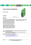
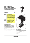
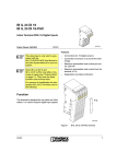
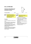
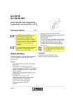
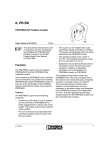
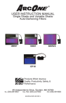
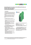
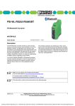
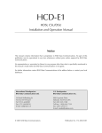
IBS CT 24 IO GT-T
IBS CT 24 IO GT-T/NPF
Gateway Between Two INTERBUS Systems
5 1 7 5 C 0 0 1
Data Sheet 517504
m
07/2003
Features
–
Electrical isolation of INTERBUS systems
–
Electrical isolation between supply voltage
and communications power
–
–
s.
co
Remote bus connection via
MINI-COMBICON
LED diagnostic and status indicators
DIN rail mounting
po
ne
The item versions
IBS CT 24 IO GT-T and
IBS CT 24 IO GT-T/NPF only differ in
"Two-way error message in the event
of an INTERBUS system failure" (see
page 9). Function and
technical data are identical.
–
nt
This data sheet is only valid in association with the
IBS SYS PRO INST UM E
User Manual.
in
ec
om
)RUJUHDWHUFODULW\WKH2UGHU'HVLJ
QDWLRQ IBS CT 24 IO GT-T LVXVHG
WKURXJKRXWWKLVGRFXPHQW
Product Description
IN
T E R
B
8
U S
0
8
0
S 2
S 1
U L R C B A R D
U L R C B A R D
T y p e : IB S C T 2 4 IO G T -T
O rd . N o .: 2 7 1 9 4 7 0
1
R e m o te O U T 1
2
3
4 5 6
3 b
7
1 b
8
9
1 0
R e m o te O U T 2
7
1 5
7
1 5
M o d u le Id e n t.: 0 3
R e m o te IN 1
R e m o te IN 2
5 1 7 5 A 0 0 8
Figure 1
IBS CT 24 IO GT-T module
on
l
The module is used for the I/O connection of two
INTERBUS systems. It has the same function as
two standard I/O modules on which the inputs
and outputs are cross wired. Cross wiring permits the transmission of data from one system
part to another. Data width can be configured
between one byte and ten words using a rotary
switch.
517504
1
IBS CT 24 IO GT-T (/NPF)
9 1 0 1 b .3b.
Positions of the Connections, Diagnostic and Status Indicators
3
m
4
5
6
7
8
8
2
3
4
5
6
8
U S
0
8
0
s.
B
S 2
S 1
U L R C B A R D
U L R C B A R D
T y p e : IB S C T 2 4 IO G T -T
O rd . N o .: 2 7 1 9 4 7 0
1
2
3
4 5 6
3 b
R e m o te O U T 1
7
nt
T E R
8
9
1 0
1 b
ne
IN
co
1
2
1
R e m o te O U T 2
7
1 5
Figure 2
in
ec
B u s e le c tr o n ic s
R e m o te b u s 1
M o d u le Id e n t.: 0 3
R e m o te IN
2
7
S ta tu s
in d ic a to r
B u s e le c tr o n ic s
R e m o te b u s 2
5 1 7 5 C 0 0 3
Front view of the module
Diagnostic indicators for remote bus 1
2
Configuration switch S1
3
Status indicators for remote bus 1
4
Status indicators for remote bus 2
5
Pushbutton S2
6
Diagnostic indicators for remote bus 2
7
7-segment display
8
Sticker, supplied with the module
on
l
1
2
1 5
po
1
om
R e m o te IN
7
The valid configuration can be entered on the sticker supplied, which
can then be placed over the S1 selector switch to prevent accidental adjustment of the configuration.
517504
IBS CT 24 IO GT-T (/NPF)
Connector Pin Assignment for Each Remote
Bus
Des.
Signal
7-Segment
Display
Remote OUT x Outgoing remote bus
Module configuration
(see page 4)
For Each Remote Bus
UL
Green Supply voltage for the bus interface
RC
Green Remote bus cable check
BA
Green Bus active
m
Incoming remote bus
RD
Red
Remote bus disconnected
0 to 15
Yellow
Status indicators
(see page 4)
nt
s.
Remote IN x
Color Meaning
co
Terminal
Sequence
Local Diagnostic and Status Indicators
ne
Configuration Switch S1
po
The configuration setting can only be read after power up. It is not possible to modify the
configuration during operation. If the switch position is changed during operation, the configuration is only changed and displayed after a new power up. 3RZHUXSDIWHUDQ\FKDQJ
HVWRWKHFRQILJXUDWLRQVRWKDWWKHFRQILJXUDWLRQLVUHDG
om
The configuration of the IBS CT 24 IO GT-T module can be modified using the configuration switch.
Use a screwdriver to change the switch position. The set configuration is displayed on the 7-segment
display when the system is switched on.
in
ec
Possible configurations
1
2
3
4
5
6
7
8
9
10 1b. 3b.
Register Length
1
2
3
4
5
6
7
8
9
10
on
l
Switch Setting
Word(s)
1
3
(X)
1
Byte*
1
1
1
Word
Length Code (hex)
01 02 03 04 05 06 07 08 09 0A 81 83 01 01 01 01
7-Segment Display
1
2
3
4
5
6
7
8
9
A
1.
3.
1
1
1
1
(X): Reserved, set internally to a register length of one word (modifications reserved)
*
Byte lengths can only be set when using a controller board of firmware version 4.x or later, or a
controller board that supports byte operation.
517504
3
IBS CT 24 IO GT-T (/NPF)
Pushbutton S2
Do not press the pushbutton during power up, otherwise an internal test function will be
activated. This test mode can only be exited by switching off the supply voltage.
The pushbutton is used to select the word or byte number of the output information, which is to be
displayed for each bus system using the 16 LEDS. The selected word or byte number is displayed
on the 7-segment display.
co
Display
Word
Byte
1
2
3
4
5
6
7
8
9
10
1
2
3
1
2
3
4
5
6
7
8
9
A
1.
2.
3.
nt
7-Segment Display
s.
No. of the Output
Word or Byte
m
Meaning of the display
The maximum word number, byte number or
register length of the set configuration is always displayed when the supply voltage is
switched on.
2
As soon as the pushbutton is pressed, the
corresponding word or byte number of the
output information, shown on the status display, is indicated. Once the maximum number for the corresponding configuration is
reached, the first number is displayed again
when the pushbutton is pressed.
in
ec
om
po
1
ne
Two pieces of information are shown on the 7-segment display:
Please note that the byte devices are indicated by a point after the displayed byte number.
Status Indicators
on
l
The 16 status LEDs per remote bus indicate the status of the output word or byte of the corresponding
remote bus specified by the pushbutton. In byte operation the selected byte is displayed on LEDs 0
to 7, which correspond to the least significant byte.
The output information of one bus is the input information of another bus. Only the output
information of each bus is displayed by the status indicators.
4
517504
IBS CT 24 IO GT-T (/NPF)
T E R
B
8
U S
0
8
0
S 1
S 2
U L R C B A R D
U L R C B A R D
T y p e : IB S C T IO G T -T
O rd . N o .: 2 7 1 9 4 7 0
1
2
3
4 5 6
3 b
7
8
9
1 0
1 b
R e m o te O U T 2
R e m o te O U T 1
s.
IN
co
m
Installation Example
7
1 5
7
1 5
M o d u le Id e n t.: 0 3
R e m o te IN 2
1
1
2 4 V D C 2
om
po
2 4 V D C
ne
nt
R e m o te IN
R e m o te b u s 2
5 1 7 5 C 0 0 2
Installation diagram for the IBS CT 24 IO GT-T module
on
l
Figure 3
in
ec
R e m o te b u s 1
You must connect both supply voltages.
The module has a redundant supply voltage enabling both INTERBUS systems to be operated separately. If the system fails, the other bus will continue to operate without restriction if the corresponding supply voltage is present.
517504
5
IBS CT 24 IO GT-T (/NPF)
Remote Bus Connection With the Remote Bus Cable
6QDSWKHFDEOHFOLSRQWRWKHPRGXOHDWWKH
SRVLWLRQVVKRZQThe cable clips are designed for mounting the remote bus cables
to the module and provide the strain relief for
the remote bus cables.
O u tg o in g
re m o te b u s 2
In c o m in g
re m o te b u s 2
O u tg o in g
re m o te b u s 1
m
•
5 1 7 5 A 0 1 0
ne
nt
s.
2 4 V D C 1
co
2 4 V D C 2
In c o m in g
re m o te b u s 1
Press the remote bus cables into the cable
clips.
The remote bus is connected to the module
using a 10-pos. MINI-COMBICON connector.
The cable shield is connected to the housing
using a shield clamp at two MINI-COMBICON terminal points.
Observe the required bending radii
(at least 8 x cable diameter).
Plug the connector into the corresponding
terminal strips with the keying tabs facing
downwards (Figure 5).
Remote IN designates the incoming remote
bus, remote OUT the outgoing remote bus.
The supply voltage UL for the module electronics must be supplied through terminals
1 (UL+) and 2 (UL-) of the REMOTE IN connector.
on
l
•
•
Positions of remote bus connectors
in
ec
•
Position of cable clips
om
Figure 4
po
Figure 5
5 1 7 5 C 0 0 4
5 1 7 5 A 0 1 1
Figure 6
6
Completely wired module including
strain relief
517504
IBS CT 24 IO GT-T (/NPF)
Pin Assignment of the Remote IN Connector
Pin
1
2
Terminal
Designation
UL +
U L-
Signal
Description
24 V
0V
3
4
Shield Shield
6
7
8
9
A
B
C
D
E
/DO
DO
/DI
DI
Ground
Pink
Gray
Brown
Green Yellow
Terminal
Designation
L
M
Signal
Description
RBST
VCC
3
Shield
Shield
5
6
F
G
/DO
DO
Green Yellow
Shield
7
8
9
H
J
K
/DI
DI
Pink
Gray
10
Ground Shield
Brown
po
ne
Wire Color
4
s.
2
nt
1
co
Pin Assignment of the Remote OUT Connector
Pin
10
m
Wire Color
5
om
Please note that LIPRGXOHVDUHIROORZHGE\DQRWKHUPRGXOH, a wire jumper must be installed between terminals 1 (L) and 2 (M) of the remote OUT connector.
ID code
Length code
in
ec
Programming Data
03hex (03dec)
1 byte to 20 bytes
(2 bytes default)
on
l
Process data channel 8 bits to 160 bits
(16 bits default)
Input address area
1 byte to 20 bytes
Output address area
1 byte to 20 bytes
Parameter channel
(PCP)
0 bytes
Register length
1 byte to 20 bytes
517504
7
IBS CT 24 IO GT-T (/NPF)
Technical Data
General Data
Order Designation
Order Number
Housing dimensions (length x height x depth)
IBS CT 24 IO GT-T
IBS CT 24 IO GT-T/NPF
27 19 47 0
27 40 43 6
204 mm x 77 mm x 34 mm
(8.031 in. x 3.031 in. x 1.339 in.)
co
m
Total power consumption (HOHFWURQLFVEXVLQWHU 5.76 W typical
IDFH,2)
From -20°C to +70°C (-4°F to 158°F)
Permissible storage temperature
From -40°C to +85°C (-40°F to 185°F)
Degree of protection
IP20, DIN 40050, IEC 60529
Class of protection
Class 3 VDE 0106, IEC 60536
Humidity
30% to 75%
Air pressure (operation)
86 kPa to 106 kPa, 1500 m (4921 ft.) above sea
level
ne
nt
s.
Permissible operating temperature
Test voltage
po
Electrical isolation
Supply voltage/logic
500 V AC, 1 minute, 50 Hz
500 V AC, 1 minute, 50 Hz
Logic/functional earth ground
500 V AC, 1 minute, 50 Hz
INTERBUS system 1/INTERBUS system 2
500 V AC, 1 minute, 50 Hz
Protective ground
Weight
on
l
Interface
in
ec
Preferred mounting position
om
Supply voltage/functional earth ground
Panel mounting on DIN rail
Using DIN rail
240 g, typical
Protocol mode
2-wire asynchronous protocol, 500 kBd
Incoming remote bus
10-pos. MINI-COMBICON connector
Outgoing remote bus
10-pos. MINI-COMBICON connector
Maximum distance to the next remote bus device 400 m (1312.336 ft.)
Remote bus end encoding
8
Jumper on the MINI-COMBICON connector of
the outgoing remote bus interface
517504
IBS CT 24 IO GT-T (/NPF)
Power Consumption
Supply voltage UL
24 V DC
Nominal current consumption at UL
240 mA, typical
Power consumption at UL (24 V supply voltage) 5.76 W, typical
Supply Voltage (UL)
24 V DC
Permissible ripple
3.6 Vpp within the permissible voltage range
Permissible voltage range
(ripple included)
20 V DC to 30 V DC
Current consumption at UL
240 mA, typical
Protection against polarity reversal
Yes, through diode connected in series
Surge voltage protection
35 V (0.5 s)
Failure detection
Yes
ne
nt
s.
co
m
Nominal value
Module Error Messages
om
Failure of an INTERBUS device
po
Power consumption at UL (24 V supply voltage) 5.76 W typical
Yes
Two-way error message in the event of an INTERBUS system failure
IBS CT 24 IO GT-T
No
on
l
in
ec
IBS CT 24 IO GT-T/NPF
Yes
517504
9
IBS CT 24 IO GT-T (/NPF)
Ordering Data
Order Designation
Order No.
INTERBUS coupling module
IBS CT 24 IO GT-T
27 19 47 0
INTERBUS coupling module
IBS CT 24 IO GT-T/NPF
27 40 43 6
Replacement cable clips (10 pcs)
IBS CT RELIEF
27 25 46 4
Replacement shield clamp (1 piece)
IBS RB-SHIELD
27 22 74 2
Replacement remote bus connector set
IBS RB PLSET/FRONT-MC 1,5/10
27 22 76 8
“Configuring and Installing INTERBUS”
User Manual
IBS SYS PRO INST UM E
27 43 80 2
s.
co
m
Description
on
l
in
ec
om
po
© Phoenix Contact 07/2003 Technical modifications reserved TNR 94 08 47 0
ne
nt
0DNHVXUH\RXDOZD\VXVHWKHODWHVWGRFXPHQWDWLRQ
,WLVDYDLODEOHWRGRZQORDGRQWKH,QWHUQHWDW www.phoenixcontact.com.
Phoenix Contact GmbH & Co. KG
Flachsmarktstr. 8
32825 Blomberg
Germany
+ 49 - (0) 52 35 - 3-00
+ 49 - (0) 52 35 - 3-4 12 00
www.phoenixcontact.com
Worldwide Locations:
www.phoenixcontact.com/salesnetwork
10
517504