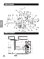
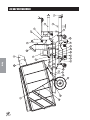
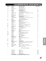
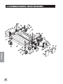
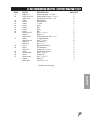
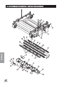
1
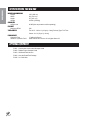
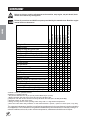
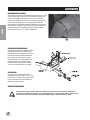
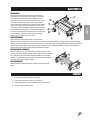
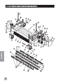
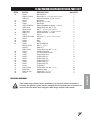
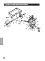
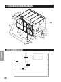
PARTS & SERVICE
MANUAL
Big Vac
Models 72-000-A
Starting Serial # 72088
Novmeber, 2002
SMITHCO PRODUCT SUPPORT
1-800-891-9435
Hwy SS and Poplar Avenue, Cameron WI 54822
E-mail: [email protected]
Introduction
CONTENTS
Introduction ......................................... 1-10
Service
Diagrams
Parts
Accessories
Introduction ................................................................................. 1-4
Introduction ................................................................................. 1
Safe Practices ............................................................................. 2
PTO Safety Warnings ................................................................. 3
Specifications .............................................................................. 4
Optional Equipment .................................................................... 4
Service ........................................................................................ 5-11
Maintenance ........................................................................... 5-6
Overloading Debris Hopper and Vacuum Housing Wear ............ 7
Service Chart .............................................................................. 8
End User’s Service Chart ............................................................ 9
Adjustments ......................................................................... 10-11
Storage ..................................................................................... 11
Diagrams ...................................................................................12-13
Hydraulic Diagram ...............................................................12-13
Hydraulic Schematic ................................................................. 12
Parts ..........................................................................................14-31
Big Vac Main ........................................................................14-15
Control Panel .......................................................................16-17
Oil Tank ................................................................................18-19
Blower Housing ....................................................................20-21
Vacuum Housing Belts and Tensioners ................................ 22-23
Hopper .................................................................................24-25
72-151 Hydraulic Valve ........................................................26-27
78-416 3 Bank Hydraulic Valve ........................................... 28-29
72-048 Axle ..........................................................................30-31
72-055 PTO Shaft ................................................................30-31
Accessories ..............................................................................32-52
72-001 Combination Sweeper - Verticut Head ..................... 32-37
72-002 Rubber Finger Sweeper Head .................................. 38-41
72-005 Brush Reel Sweeper Head with 72-006 Brush Only 42-45
72-004 Over-The-Road Towing Package ............................ 46-48
72-003 Hand Held Vacuum Hose ......................................... 50-52
Reference ..................................................................................53-54
Decal List .................................................................................. 53
Quick Reference Replacement Parts ........................................ 54
Warranty .......................................................... Inside Back Cover
Reference
Thank you for purchasing a
product.
Read this manual and all other manuals pertaining to the Big Vac carefully as they contain safety, operating,
assembly and maintenance instructions. Failure to do so could result in personal injury or equipment damage.
Keep manuals in a safe place after operator and maintenance personnel have read them. Right and left sides are
from the operator’s seat, facing forward.
All
machines have a Serial Number and Model Number. Both numbers are needed when ordering
parts. The serial number plate on the Big Vac is located on the front cross member of the frame.
For easy access record your Serial and Model numbers here.
Information needed when ordering replacement parts:
1. Model Number of machine
2. Serial Number of machine
3. Name and Part Number of part
4. Quantity of parts
1
Introduction
INTRODUCTION
SAFE PRACTICES
Introduction
1. It is your responsibility to read this manual and all publications associated with this machine (engine,
accessories and attachments).
2. Never allow anyone to operate or service the machine or its attachments without proper training and
instructions. Never allow minors to operate any equipment.
3. Learn the proper use of the machine, the location and purpose of all the controls and gauges before you
operate the equipment. Working with unfamiliar equipment can lead to accidents.
4. Wear all the necessary Personal Protective Equipment (PPE) to protect our head, eyes, ears, hands and
feet. Ear and eye protection are required. Operate the machine only in daylight or in good artificial
light.
5. Inspect the area where the equipment will be used. Beware of overhead obstructions and underground
obstacles. Stay alert for hidden hazards.
6. Never operate equipment that is not in perfect working order or without decals, guards, shields, or other
protective devices in place.
7. Never disconnect or bypass any switch.
8. Carbon monoxide in the exhaust fumes can be fatal when inhaled, never operate a machine without proper
ventilation.
9. Never use your hands to search for oil leaks. Hydraulic fluid under pressure can penetrate the skin and
cause serious injury.
10. This machine demands your attention. To prevent loss of control or tipping of the vehicle:
A.
Use extra caution in backing up the vehicle. Ensure area is clear.
B.
Do not stop or start suddenly on any slope.
C.
Reduce speed on slopes and in sharp turns. Use caution when changing directions on slopes.
D.
Stay alert for holes in the terrain and other hidden hazards.
E.
Operate equipment up and down slopes, never across the face.
11. Before leaving operator’s position for any reason:
A
Disengage all drives.
B.
Lower all attachments to the ground.
C.
Shut engine off and remove the ignition key.
12. Keep hands, feet and clothing away from moving parts. Wait for all movement to stop before you clean,
adjust or service the machine.
13. The rubber fingers, sweeper and vacuum pick up and propel debris and small objects in machines path
during operation. Keep the area of operation clear of all bystanders.
14. Never carry passengers.
15. Use parts and materials supplied by
only. Do not modify any function or part.
16. Avoid sharp turns. Watch the tires of the tractor while turning to make sure they do not contact the tongue
of the Big Vac.
17. Shut down power source before attempting to unclog any part of the machine.
18. If reel deck and/or blower began to vibrate abnormally, immediately shut off power and determine the
cause.
These machines are intended for professional maintenance on large turf areas such as golf courses, baseball
fields, parks, recreation areas, and many other large open areas. Other use is forbidden.
2
1. Always disengage the PTO, shut off engine and remove the keys before leaving the tractor seat.
2. Keep the tractor's master shield in place at all times.
3. Missing or damaged shielding is the main reason for driveline entanglement. Keep All Guards on and in
good condition. Check guards frequently.
4. Never step across a rotating powershaft. Always walk around the revolving shaft even if guards are in
place.
5. Dress for safety. Do not wear loose fitting clothes or jewelry and keep long hair covered or pulled back.
6. The tractor drawbar should be adjusted to the length specified in the driven machine's manual. This will
help prevent driveline stress and separation on uneven terrain and in tight turns.
7. A PTO shaft may break or separate during operation if improperly installed or adjusted. Be sure PTO shaft
is installed properly.
8. Never perform maintenance or adjustments until both the driveline and the machinery have stopped
moving.
9. Warn anyone who might come near an operating PTO about the entanglement hazard.
10. Regularly test driveline guards by spinning or rotating them to ensure the have not become stuck to the
shaft.
11. Always use the driveline recommended for your machine. Never switch drivelines among different machines.
12. Reduce PTO shaft abuse by observing the following:
a. Avoid tight turns that pinch rotating shafts between the tractor and machine.
b. Keep excessive telescoping to a minimum.
c. Engage power to the shaft gradually.
d. Avoid over tightening of slip clutches on PTO driven machines.
3
Introduction
PTO SAFETY WARNINGS
SPECIFICATIONS FOR BIG VAC
Introduction
WEIGHTS AND DIMENSIONS
Length
Width
Height
Weight
180" (458 cm)
84" (214 cm)
87" (221 cm)
3500 lb (1588 kg)
SOUND LEVEL
At Ear Level
92 dB (Use ear protection while operating)
PTO SHAFT
Maximum RPM
540
TIRES & WHEELS
Two 26.5 - 1400 x 12 (18 psi (1.3 bar)) Fairway Type Turf Tires
Castor: 6 x 12 (20 psi (1.4 bar))
FLUID CAPACITY
Hydraulic Fluid
Grade of Hydraulic Fluid
17 gallon (64 liters)
SAE 10W-40 API Service SJ or higher Motor Oil
OPTIONAL EQUIPMENT
72-001 Combination Verticut and Sweeper Head
72-002 Rubber Finger Sweeper Head
72-003 25ft Hand Held Vacuum
72-004 Over-the-Road Tow Package
72-245 25/16 Ball Hitch
4
MAINTENANCE
Before servicing or making adjustments to machine, stop engine on tow vehicle and remove
key from ignition.
LUBRICATION
Use No. 2 General Purpose Lithium Base Grease and lubricate every 100 hours. The Big Vac has 19 to 25
grease fittings, depending on what sweeper head you are using. All bearings are sealed bearings. When inserting grease, be careful not to ruin the seal, if this happens, replace the bearing at once. Be sure to wipe grease
fitting clean before injecting grease. Give only one or two pumps of grease at each lubrication.
REF#
1
LOCATION
One on all four castor wheels.
2
Four on the front of the blower that go to pillow blocks on blower and PTO shafts.
3
One on each mounted bearing for reel shaft. Two for finger reel. Four for combination head.
4
One on each end of the PTO shaft.
5
One on all four castor wheel mount brackets.
6
One on the jack stand.
7
One on each end of roller - Combination head only.
5
Service
Use all procedures and parts prescribed by the manufacturer's. Read the engine manual
before operation.
MAINTENANCE (CONTINUED)
TIRE PRESSURE
Caution must be used when inflating a low tire to recommended pressure. Over inflating can cause tires to
explode. Tires on the machine should be 18 psi (1.3 bar), castor wheels should be 20 psi (1.4 bar). Improper
inflation will reduce tire life considerably.
WHEEL MOUNTING PROCEDURE
1. Turn machine off and remove key.
Service
2. Be sure unit is on a level surface. Unhitch from tow vehicle if possible.
3. Block the opposite wheel then the one you are working on.
4. Loosen nuts slightly on wheel to be removed.
5. Jack up machine being careful not to damage underside of machine.
6. Remove nuts, remove wheel.
7. Place new wheel on hub lining up bolt holes.
8. Torque nuts to 64-74 ft/lb (87-100 Nm) using a cross pattern. Torque again after first 10 hours and every
200 hours thereafter.
9. Lower machine to ground and remove blocks and jack.
HYDRAULIC OIL
1. Use SAE 10W-40 API Service SJ or higher motor oil.
2. For proper warranty, change oil every 500 hours or annually, which ever is first and change the filter after
the first 20 hours, then at 100 hours, then every 250 hours thereafter.
3. Inspect hydraulic lines for damage or leaks. Never use hands to inspect leaks.
4. Check hydraulic fluid level in tank. Look at the sight gauge on the front left side of the tank. The oil level
should be at 90°C (194°F). If level is low, add SAE 10W-40 API Service SJ or higher motor oil.
5. After changing oil and/or filter, operate the machine for a few minutes. Check oil level and for leaks.
6. Always use caution when filling hydraulic oil tank or checking level to keep system free of contaminants.
Check and service more frequently when operating in extremely cold, hot or dusty conditions.
7. If natural color of fluid is now black or smells burnt, it is possible that an overheating problem exists.
8. If fluid becomes milky, water contamination may be a problem.
9. If either of the above conditions happen, change oil and filter immediately after fluid is cool and find cause.
Take fluid level readings when system is cold.
10. In extreme temperatures you can use straight weight oil. We recommend SAE 30W API Service SJ or
higher when hot (above 90°F (33°C)) and SAE 10W API Service SJ or higher when cold (below 32°F (0°C))
ambient temperature. Use either motor oil or hydraulic oil, but do not mix.
11. Oil being added to the system must be the same as what is already in the tank. Mark tank fill area as to
which type you put in.
VERTICUT REEL VALVE HANDLE
If the rubber finger sweeper head is installed on your unit and verticut reel handle is activated, the hydraulic system may be damaged due to overheating the oil. Remove the
verticut reel valve handle when using the rubber finger sweeper head (72-002).
6
MAINTENANCE (CONTINUED)
HOPPER LIFT SAFETY
The Hopper Lift Safety is used to support the ram on
the hopper bottom in the extended position so you
may service or repair the machine under the hopper.
When not in use the Hopper Lift Safety can be stored
on the hopper bed frame.
OVERLOADING DEBRIS HOPPER AND VACUUM HOUSING WEAR
SMITHCO SWEEPER-VACS ARE DESIGNED TO CARRY THE FOLLOWING MAXIMUM LOADS:
Model 72-000 Big Vac
1500 lbs. (608 kg)
PLEASE NOTE THE FOLLOWING:
1. Loads heavier than that will damage the unit.
2. Such damage is not covered by warranty.
3. Overloading is particularly easy when collecting aerifier cores.
4. The hoppers on the Big Vac and V62 are large in order to hold 7 and 4 cubic yards respectively, of thatch,
grass clippings, leaves and trash.
5. They will not hold 7 or 4 cubic yards of aerifier cores.
6. The maximum depth (in the debris hopper) of aerifier cores is:
Model 72-000 Big Vac
12 in. (30 cm)
VACUUM HOUSING WEAR
The Big Vac & V62 are fitted with a wear resistant liner in the vacuum housing. This will provide additional husing
life. Be sure the following points are explained to the user:
1. The vacuum housing and impeller must be cleaned each time the unit is used so the housing liner is
inspected daily. Only Smithco Sweeper-Vacs provide a clean out/inspection port for easy inspection and
cleaning.
2. When bare steel is visible at any point in the housing lining, the lining must be replaced. It is expected the
liner will wear and be replaced. It is a vast improvement over competitive units with no liners.
3. Replacement of the liner or the vacuum housing due ti wear is normal and is not covered by warranty.
4. Collection of aerifier cores causes extreme wear on the liner (and if unchecked, on the housing).
5. Caution users that, while Smithco Sweeper-Vacs do an excellent job collecting cores, the lining (and the
housing) will wear quickly in such use.
RUBBERIZED BOOT
The rubberized boot between main unit and sweeper head is subject to wear and damage from debris. Unless
defecetive, replacement of this boot is not covered by warranty.
7
SERVICE CHART
Before servicing or making adjustments to the machine, stop engine, set park break, block
wheels and remove key from ignition.
400 Hours
R
R
C
C
C
C
Every 500 Hours/Yearly
300 Hours
250 Hours
200 Hours
C R R R
R
R
C
C C
C
R C C
R
R C C C R
R C C
C
Daily
100 Hours
Service
¤£ Engine Oil
Engine Oil Filter
Engine for Leaks and Loose Parts
‡ Air Cleaner (Paper Element)
‡ Air-Cleaner (Foam Element every 25 hours)
Spark Plugs (Clean and Gap/Replace)
Valve Clearance
Idle Speed
‡ Cooling System
Belts and Hoses
* Tire Pressure
Visual Inspection of Tires
Fuel Level
Fuel Filter
Hydraulic Oil
†Hydraulic Oil Filter
Hydraulic System for Leaks and Loose Parts
Battery Electrolyte Level
Clean Battery Terminals
§ Torque Lug Nuts
Lubricate Reel and Blower Shaft Bearings
Lubricate Castor Wheels (Every 25 hrs)
As Required
Follow all procedures and ONLY use parts prescribed by the manufacturer. Read the engine
manual before maintenance.
R
R
C
R
R
R
C
C
C
C
C
C C
C C C
C
C
C
C
C C
C C C
C
C C
C C C
C C
R
R
C
C C
C C R
R
R
C
C C
C C C
C C
C C C
C
C
C
C C
C
C
C C
C=Check or Clean at specified intervals
R=Replace at specified intervals
* Tire pressure: Machine Tires 18 psi (1.3 bar) Castor Wheels 20 psi (1.4 bar)
† Replace hydraulic filter after the first 20, 100, and every 250 there after.
§ Torque tire nuts after the first 10 hours and every 200 hours there after (64 to 74 ft/lb (87-100 Nm))
¤ Kawasaki change oil after first 8 hours.
£ Change oil every 25 hours when operating under heavy load or in high ambient temperatures.
‡ Clean more often under dusty conditions or when airborne debris is present , replace air cleaner parts, if very dirty.
The suggested maintenance checklist is not offered as a replacement for the manufacturer’s engine manual but
as a supplement. You must adhere to the guidelines established by the manufacturer for warranty coverage. In
adverse conditions such as dirt, mud or extreme temperatures, maintenance should be more frequent.
8
Service
Every 500 Hours/Yearly
400 Hours
300 Hours
250 Hours
200 Hours
100 Hours
As Required
Daily
END USER'S SERVICE CHART
¤£ Engine Oil
Engine Oil Filter
Engine for Leaks and Loose Parts
‡ Air Cleaner (Paper Element)
‡ Air-Cleaner (Foam Element every 25 hours)
Spark Plugs (Clean and Gap/Replace)
Valve Clearance
Idle Speed
‡ Cooling System
Belts and Hoses
* Tire Pressure
Visual Inspection of Tires
Fuel Level
Fuel Filter
Hydraulic Oil
†Hydraulic Oil Filter
Hydraulic System for Leaks and Loose Parts
Battery Electrolyte Level
Clean Battery Terminals
§ Torque Lug Nuts
Lubricate Reel and Blower Shaft Bearings
Lubricate Castor Wheels (Every 25 hrs)
C=Check or Clean at specified intervals
R=Replace at specified intervals
* Tire pressure: Machine Tires 18 psi (1.3 bar) Castor Wheels 20 psi (1.4 bar)
† Replace hydraulic filter after the first 20, 100, and every 250 there after.
§ Torque tire nuts after the first 10 hours and every 200 hours there after (64 to 74 ft/lb (87-100 Nm))
¤ Kawasaki change oil after first 8 hours.
£ Change oil every 25 hours when operating under heavy load or in high ambient temperatures.
‡ Clean more often under dusty conditions or when airborne debris is present , replace air cleaner parts, if very dirty.
9
ADJUSTMENTS
Service
ADJUSTMENT OF BELT TENSIONER
There are four maximum belt tensioners on the Big Vac. Two
control the tension on the belts on the blower housing, one
each on the finger reel and the thatcher reel. The proper
tension of the idler should be 12 to 15 as per the gauge (A)
on the side of the tightener. Over tightening the belt will
shorten the life of the belt and the machine may not perform
to the best of its ability. To adjust belt tensioner, loosen bolt
holding tensioner. Bring idler pulley tight to belts and turn
tensioner into belts to 15°. Tighten holder bolt.
CONTROL PANEL ADJUSTMENT ARM
On the right hand side of machine is the
adjustment lock arm, by lifting up you
can adjust the control panel by moving it
forward or rearward. Make certain that
the lock arm is locked back in place
after adjustment. For up and down adjustment loosen the four adjustment
bolts place the control panel to where
you want it and tighten the four bolts.
HITCH OPTIONS
You may use the clevis hitch that is
shipped with your machine or a 25/16 ball
hitch that is an optional accessory. Both
mount in the same location with three
different bolt hole options.
VERTICUT REEL VALVE HANDLE
If the rubber finger sweeper head is installed on your unit and verticut reel handle is
activated, the hydraulic system may be damaged due to overheating the oil. Remove the
verticut reel valve handle when using the rubber finger sweeper head (72-002).
10
ADJUSTMENTS
Service
CASTOR WHEELS
The castor wheel height spacers are quick spacers
meaning they have a slot cut out of them. The castor
fork shaft has two flats on it near the bottom. To remove the quick spacers (A) lift up on the castor wheel
(C) and remove lynch pin (B). Let the castor wheel
come down some, take the quick spacer up and turn it
until you feel the flats on the shaft then pull out. This
removes the spacers below the castor arm (D), reverse
the procedure to add spacers. The thin quick spacers
must not be placed in line with the flats on the shaft or
they will fall out. Check the tire pressure on castor
wheels, they should be 20 psi (1.4 bar).
DOUBLE REEL HOUSING
Normal setting is three slots down in front and two
slots down in rear (both sides). You may want to change the normal setting to compensate for wear of the flail
blades or sweeper fingers or to sweep without cutting. To do this loosen bolt (E) and remove bolts (F) both sides.
Then tip the reel housing to the desired position. Replace bolts and tighten all bolts. This can also be done in
conjunction with the castor wheel height adjustment spacers.
ANTI SCALP ROLLER (DOUBLE REEL)
Normal setting for the anti scalp roller is with the machine on a
level hard surface. Normal setting is with the bottom of the roller to
be ¼ inch above the flail blades, with flail blades in their lowest
position. To adjust loosen the four bolts (G) both sides and slide
the roller up or down. Tighten all bolts.
SINGLE REEL HOUSING
Normal setting is two slots down (H) both front and rear (both
sides).
STORAGE
1. Before storing clean machine thoroughly.
2. Check bolts and nuts, tighten as necessary.
3. Make all repairs that are needed and remove any debris.
4. Store in a clean and dry area.
11
HYDRAULIC DRAWING
Diagrams
HYDRAULIC SCHEMATIC
12
HYDRAULIC PARTS LIST
1
2
3
4
5
6
7
8
9
10
11
12*
13
14
15
16
17
18*
19
20
21
22
23
24
25
26
27
28
29
30
31*
32
*
PART#
DESCRIPTION
72-079
18-276
72-146
60-334
72-096
34-058
72-065
72-040
72-040-01
72-040-02
72-064
72-070
72-071
10-187
14-273
72-187
72-187-01
72-187-02
72-073
72-044
72-045
72-072
18-170
78-219
78-219-01
78-219-02
72-075
72-074
72-043
72-046
HRR-150
72-068
72-074
72-067
72-063
72-151
72-069
78-416
72-062
72-185
72-185-01
72-185-02
72-066
Suction Hose
Tee Fitting 11/4
Filter
Filter Element (replacement only)
Hydraulic Tank
Swivel Tee
Hydraulic Hose
Cylinder
Seal Kit
Pin with Clips (part of 72-040)
Hydraulic Hose
Hydraulic Hose
Hydraulic Hose
Hydraulic Cylinder
Seal Kit
Hydraulic Motor (Thatch Reel)
Seal Kit
Drive Coupler
Hydraulic Hose
Quick Coupler 3/8 Male End
Quick Coupler 3/8 Female End
Hydraulic Hose
Tee Fitting
Hydraulic Motor (Reel)
Seal Kit
Drive Coupler
Hydraulic Hose
Hydraulic Hose
Quick Coupler ½ Male End
Quick Coupler ½ Female End
Retaining Ring 1½" External
Hydraulic Hose
Hydraulic Hose
Hydraulic Hose
Hydraulic Hose
Hydraulic Valve
Hydraulic Hose
Hydraulic 3 Bank Valve
Hydraulic Hose
Hydraulic Double Pump
Front Pump Seal Kit
Rear Pump Seal Kit
Hydraulic Hose
QUANTITY
2
1
1
1
1
1
1
1
1
2
1
1
2
1
1
1
1
1
2
1
1
1
1
1
1
1
1
1
4
4
8
2
2
2
1
1
1
1
1
1
1
1
1
Diagrams
REF#
No other parts are replaceable for hydraulic motor or pump.
HYDRAULIC PRESSURES
Pump Displacement
FRONT
.90 in3/rev
REAR
.40 in3/rev
Pump Input Speed (up to)
4000 rpm
4000 rpm
Max. Operating Pressure
3600 psi
3600 psi
Max. Inlet Vacuum
10 in. Hg
10 in. Hg
Max. Case Pressure
80 psi
80 psi
13
BIG VAC MAIN DRAWING
Parts
14
BIG VAC MAIN PARTS LIST
PART#
DESCRIPTION
30
31
HCP-12-175
HP-18-100
72-110
72-111
72-108
HB-12-13-125
HNTL-12-13
72-081
72-109
72-096
HST-516-18-075
72-143
78-274
72-055
78-244
78-240
72-149
72-150
HB-12-13-150
HW-12
HNFL-12-13
HCP-12-200
HP-18-100
18-169
10-187
14-273
HCP-12-200
HP-18-100
HCP-34-200
HP-18-100
72-148
72-103
HCP-100-200
HHP-18-100
72-040-02
72-040
72-040-01
23-184
72-080
HMB-34-10
HP-18-100
72-042
33-072-01
72-042-02
42-040
HNJ-34-16
72-099
72-177
HB-38-16-250
HNW-38-16
78-365
72-183
Clevis Pin 1/2 x 13/4
Cotter Pin 1/8 x 1
Hopper Chute
Middle Chute
Reel Lift Cross Bar
Bolt 1/2 - 13 x 11/4
Lock Nut 1/2 - 13
Vacuum Housing
Blower Chute
Hydraulic Oil Tank
Truss Head Machine Screw 5/16 - 18 x 3/4
Front PTO Cover
Cage Nuts
PTO Shaft
3
/4" Clevis
Jack
Right PTO Cover Bracket
Left PTO Cover Bracket
Bolt 1/2 -13 x 11/2
Washer 1/2
Flange Whiz Lock Nut 1/2 - 13
Clevis Pin 1/2 x 2
Cotter Pin 1/8 x 1
Adapter
Hydraulic Cylinder
Seal Kit
Clevis Pin 1/2 x 2
Cotter Pin 1/8 x 1
Clevis Pin 3/4 x 2
Cotter Pin 1/8 x 1
Sway Bar
Reel Lift Rod
Clevis Pin 1 x 2
Bridge Pin 1/8 x 1
Pin with Clips (part of 72-040)
Hydraulic Cylinder
Seal Kit
Male Connector
Main Frame
Machine Bushing 3/4 x 10GA
Cotter Pin 1/8 x 1
Tire and Wheel
Tire W26.5 x 14.00 - 12 4 Ply
Wheel
Yoke End
Jam Nut 3/4 - 16
Tailgate Lift Rod
Hopper Lift Safety
Bolt 3/8 - 16 x 21/2
Wing Nut 3/8 - 16
Adapter with Orfice
Guide Bumpers
2
2
1
1
1
2
2
1
1
1
6
1
6
1
1
1
1
1
4
4
4
2
2
2
1
1
2
2
2
2
1
2
4
4
2
1
1
2
1
6
2
2
2
2
4
4
2
1
2
2
1
2
NS
72-140
Boot (Connects vacuum hosing to reel deck)
1
1
2
3
4
5
6
7
8
9
10
11
12
13
14
15
16
17
18
19
20
21
22
23
24
25
26
27
28
29
QUANTITY
Parts
REF#
Note: if you are using the 72-004 Over-The-Road Towing Package, use 72-159 Tire and Wheel.
15
CONTROL PANEL DRAWING
Parts
16
CONTROL PANEL PARTS LIST
1
2
3
4
5
6
7
8
9
10
11
12
13
14
15
16
17
18
19
20
21
22
23
24
25
26
27
28
29
PART#
DESCRIPTION
72-120
HB-38-16-250
HNTL-38-16
72-121
HB-14-20-200
HW-14
HNFL-14-20
HB-14-20-150
HW-14
HNFL-14-20
72-151
72-095
72-054
78-418
78-417
78-416
HB-38-16-250
HW-38
HNTL-38-16
72-055
78-240
78-244
78-245
HB-12-13-350
HNTL-12-13
72-086
HB-12-13-125
HNTL-12-13
60-323
HB-516-18-100
HW-516
HNTL-516-18
15-020
72-093
72-080
HB-12-13-150
HW-12
HNFL-12-13
72-181
72-119
HB-38-16-275
HW-38
HNTL-38-16
72-175
72-184
Adjustment Leg
Bolt 3/8 - 16 x 21/2
Lock Nut 3/8 - 16
Control Panel Leg
Bolt 1/4 - 20 x 2
Washer 1/4
Flange Whiz Lock Nut 1/4 - 20
Bolt 1/4 - 20 x 11/2
Washer 1/4
Flange Whiz Lock Nut 1/4 - 20
Hydraulic Valve
Control Panel
Decal, Control Panel
Bent Handle
Straight Handle
3-Bank Hydraulic Valve
Bolt 3/8 - 16 x 21/2
Washer 3/8
Lock Nut 3/8 - 16
PTO Shaft
Jack
3
/4 Clevis
25/16 Ball Hitch (Optional)
Bolt 1/2 - 13 x 31/2 (comes with 78-244 and 72-245)
Lock Nut 1/2 - 13 (comes with 78-244 and 72-245)
Tongue
Bolt 1/2 - 13 x 11/4
Lock Nut 1/2 - 13
Spring
Bolt 5/16 - 18 x 1
Washer 5/16
Lock Nut 5/16 - 18
Grip
Adjustment Lock Arm
Main Frame
Bolt 1/2 - 13 x 11/2
Washer 1/2
Flange Whiz Lock Nut 1/2 - 13
Blower Housing
Control Panel Adjustment Bracket
Bolt 3/8 - 16 x 23/4
Washer 3/8
Lock Nut 3/8 - 16
Lining Holder
Wear Cover
QUANTITY
1
3
3
1
2
2
2
3
3
3
1
1
1
2
1
1
3
6
3
1
1
1
1
2
2
1
8
8
1
1
2
1
1
1
1
4
4
4
1
2
1
2
1
1
Parts
REF#
17
OIL TANK DRAWING
Parts
18
OIL TANK PARTS LIST
1†
2
3
4
5
6
7
8
9
10
11
12
13*
14*
15
16
17
18
19
20
21
22*
23*
24
25
26
27
†
PART #
DESCRIPTION
72-185
72-185-01
72-185-02
18-331
18-265
78-237
HSSHS-38-16-063
HWK-316-063
72-033
18-346
72-079
18-276
18-347
18-160
72-146
60-334
18-345
72-041-01
72-041-02
72-096
HB-12-13-125
HNFL-12-13
72-181
18-204
34-129
34-058
18-315
72-041-04
72-041-03
72-178
HB-12-13-150
HW-12
HNTL-12-13
HB-38-16-100
HW-38
HNTL-38-16
72-179
Hydraulic Double Pump
Front Pump Seal Kit
Rear Pump Seal Kit
Adapter
Elbow
Hub
Set Screw 3/8 -16 x 5/8 (part of 78-237)
Woodruff Key
Pulley
Elbow
Suction Hose
Tee
Male Elbow
Nipple
Oil Filter
Filter Element (Replacement Only)
Straight Male Pipe Adapter
Suction Strainer
Filler / Breather
Hydraulic Oil Tank (includes all * items)
Bolt 1/2 - 13 x 11/4
Flange Whiz Lock Nut 1/2 -13
Blower Housing
Elbow
Adapter
Swivel Tee
Reducer Bushing
Magnetic Drain Plug
Sight Gage
Hydraulic Motor Mount
Bolt 1/2 - 13 x 11/2
Washer 1/2
Lock Nut 1/2 - 13
Bolt 3/8 -16 x 1
Washer 3/8
Lock Nut 3/8 -16
Tensioner Arm
QUANTITY
1
1
1
1
1
1
2
1
1
2
2
1
2
1
1
1
1
1
1
1
4
4
1
1
1
1
1
1
1
1
4
8
4
3
6
3
1
Parts
REF #
No other parts are replaceable for hydraulic pump
19
BLOWER HOUSING DRAWING
Parts
20
BLOWER HOUSING PARTS LIST
1
2
3
4
5
6
7
8
9
10
11
12
13
14
15
16
17
18
19
20
21
22
23
24
25
26
27
28
29
30
31
32
33
34
PART#
DESCRIPTION
HP-18-200
HNAT-114-12
72-083
HB-12-13-125
HNTL-12-13
72-094
HKSQ-14-100
HRR-150
72-156
18-339
18-338
HG-18-180
72-126
72-127
72-029
HSSHS-14-20-025
72-030
72-027
HSSHS-14-20-025
72-028
72-031
72-032
HSSHS-38-16-038
72-060
72-024
18-338
HB-58-11-250
HMB-34-10
HW-58
HNTL-58-11
72-158
HSTP-14-20-075
HNTL-14-20
48-115
72-181
72-157
HSTP-14-20-075
HNTL-14-20
72-174
HRS-316-075
72-175
72-178
HB-12-13-150
HW-12
HNTL-12-13
72-184
Cotter Pin 1/8 x 2
Thick Axle Nut 11/4 - 12
Balanced Fan
Bolt 1/2 - 13 x 11/4
Lock Nut 1/2 - 13
Blower Shaft
Square Key 1/4 x 1/4 x 1
Retaining Ring 11/2
Blower Lining 9 x 62
Anchor Coupling
Male Connector
Grease Fitting 1/8 x 180°
Brake Line 3/16 x 24
Brake Line 3/16 x 30
Pulley
Set Screw 1/4 - 20 x 1/4 (comes with 72-030)
Hub
Pulley
Set Screw 1/4 - 20 x 1/4 (comes with 72-028)
Hub
Pulley
Hub
Set Screw 3/8- 16 x 3/8 (comes with 72-032)
Keyed PTO Shaft
Pillow Blocks
Male Connector
Bolt 5/8 - 11 x 21/2
Machine Bushing 3/4 x 10GA
Washer 5/8
Lock Nut 5/8 - 11
Trap Door Lining
Phillip Head Machine Screw 1/4 - 20 x 3/4
Top Lock Nut 1/4 - 20
Adjustable Draw Latch
Blower Housing
Blower Lining 9 x 41
Phillip Head Machine Screw 1/4 - 20 x 3/4
Top Lock Nut 1/4 - 20
Blower Housing Access Door
Rivet 3/16 x 3/4
Lining Holder
Hydraulic Motor Mount
Bolt 1/2 - 13 x 11/2
Washer 1/2
Lock Nut 1/2 - 13
Wear Cover
QUANTITY
1
1
1
2
2
1
3
4
1
4
4
4
2
2
1
1
1
1
1
1
1
1
1
1
4
4
8
4
8
8
1
4
4
2
1
1
34
34
1
3
1
1
4
8
4
1
Parts
REF#
21
VACUUM HOUSING, BELTS AND TENSIONER DRAWING
Parts
22
VACUUM HOUSING, BELTS AND TENSIONER PARTS LIST
1
2
3
4
5
6
7
8
9
10
11
12
13
14
15
16
17
18
19
20
21
22
23
24
25
26
27
28
29
PART#
DESCRIPTION
HP-18-100
HMB-12-14
72-132
78-293
72-081
HNFL-38-16
HBFL-38-16-075
25-120
HBFL-516-18-075
HNFL-516-18
72-109
72-131
HSTP-14-20-075
HNFL-14-20
8828-60
72-181
72-050
72-147
HBM-12-1.75-40
HWLM-12
HB-58-11-500
HNCL-58-11
72-027
72-028
HMB-12-14
76-275
HB-12-13-250
HNCL-12-13
78-224
72-031
72-032
HB-38-16-125
HNFL-38-16
72-033
78-237
72-185
HBM-10-1.50-30
HWLM-10
16-013
72-036
72-029
72-030
72-036
48-115
8803-114
Cotter Pin 1/8 x 1
Machine Bushing 1/2 x 14GA
Spring
Cover Plate
Vacuum Housing
Flange Whiz Lock Nut 3/4 -16
Flange Bolt 3/8 - 16 x 3/4
Handle Grip
Flange Bolt 5/16 -18 x 3/4
Flange Whiz Lock Nut 5/16 - 18
Blower Chute
Blower Chute Lining 101/2 x 151/2
Phillip Head Machine Screw ¼ -20 x ¾
Flange Whiz Lock Nut ¼ - 20
Foam Tape
Blower Housing
Idler Pulley
Tensioner
Metric Bolt 12 - 1.75 x 40 (comes with 72-025)
Metric Lockwasher 12 (comes with 72-025)
Bolt 5/8 - 11 x 5
Center Lock Nut 5/8 - 11
Pulley
Hub
Machine Bushing 1/2 x 14GA
Spacer (comes with 78-224)
Bolt 1/2 - 13 x 21/2 (comes with 78-224)
Center Lock Nut 1/2 - 13 (comes with 78-224)
Tensioner
Pulley
Hub
Bolt 3/8 - 16 x 11/4
Flange Whiz Lock Nut 3/8 - 16
Pulley
Hub
Hydraulic Double Pump
Metric Bolt 10 - 1.5 x 30 (comes with 78-224)
Metric Lockwasher 10 (comes with 78-224)
Idler Pulley
Belt 5V x 540
Pulley
Hub
Belt 5V x 540
Draw Latch
Trim Black
QUANTITY
1
1
1
2
1
12
12
1
3
3
1
1
6
6
1
1
1
1
1
1
1
1
1
1
6
1
1
1
1
1
1
2
2
1
1
1
1
1
1
2
1
1
5
2
1
Parts
REF#
23
HOPPER DRAWING
Parts
24
HOPPER PARTS LIST
1
2
3
4
5
6
7
8
9
10
11
12
13
14
15
16
17
18
19
20
21
22
23
24
25
26
PART #
DESCRIPTION
72-106
HB-14-20-250
HNFL-14-20
72-115
HSDPS-14-075
72-110
72-145
HSTP-14-20-075
HNFL-14-20
HBFL-516-18-075
HNFL-516-18
8947-18
8980-60
72-111
72-107
72-102
HW-14
HSDPS-14-075
HB-14-20-075
HNFL-14-20
72-101
72-124
72-105
72-138
HRS-316-075
72-137
HSDPS-14-075
HB-14-20-175
HNFL-14-20
72-116
HB-12-13-175
HNFL-12-13
72-098
72-123
HP-18-100
HSTP-14-20-075
HNFL-14-20
72-118
18-235
HMB-12-14
HP-18-100
72-117
18-235
HMB-12-14
HP-18-100
Left Hopper Side Frame
Bolt ¼ -20 x 21/2
Flange Whiz Lock Nut ¼ -20
Hopper Front
Stainless Pan Head Drill Screw ¼ x ¾
Hopper Chute
Hopper Chute Lining
Phillip Head Machine Screw ¼ -20 x ¾
Flange Whiz Lock Nut ¼ - 20
Flange Bolt 5/16 -18 x 3/4
Flange Whiz Lock Nut 5/16 -18
Trim Seal
Edge Seal
Middle Chute
Hopper Top
Left Hopper Cover
Washer ¼
Stainless Pan Head Drill Screw ¼ x ¾
Bolt ¼ -20 x ¾
Flange Whiz Lock Nut ¼ -20
Right Hopper Cover
Hood Stiffener
Right Hopper Side Frame
Slide Strip
Pop Rivet 3/16
Hopper Side
Stainless Pan Head Drill Screw ¼ x ¾
Bolt ¼ -20 x 13/4
Flange Whiz Lock Nut ¼ - 20
Tailgate
Bolt ½ -13 x 13/4
Flange Whiz Lock Nut ½ - 13
Hopper Floor
Pivot Pin
Cotter Pin 1/8 x 1
Phillip Head Machine Screw ¼ -20 x ¾
Flange Whiz Lock Nut ¼ - 20
Short Tailgate Lift Arm
Bushing (part of 72-118)
Machine Bushing ½ x 14 GA
Cotter Pin 1/8 x 1
Long Tailgate Lift Arm
Bushing (part of 72-117)
Machine Bushing ½ x 14 GA
Cotter Pin 1/8 x 1
QUANTITY
1
15
15
1
9
1
1
6
6
10
10
2
1
1
1
1
10
6
23
23
1
1
1
2
8
2
82
14
14
1
4
4
1
2
4
18
18
2
1
6
2
2
2
6
2
Parts
REF #
25
72-151 HYDRAULIC VALVE DRAWING
Parts
26
72-151 HYDRAULIC VALVE PARTS LIST
PART#
DESCRIPTION
8*
9
33-066-27
33-066-17
33-066-29
33-066-19
33-066-18
33-066-20
33-066-22
33-066-25
33-066-23
33-066-28
33-066-21
33-066-26
33-066-24
33-066-11
33-066-04
33-066-10
33-066-09
33-066-03
18-337
18-244
33-066-30
33-066-08
33-066-02
33-066-05
33-066-06
33-066-15
18-246
Detent Housing
Detent Plunger
Spring
Set Screw 5/16 – 24 x 3/8
Washer
Detent End Cap
Spacer
Washer
Spacer
Spacer, Spool
Center Spring
Sleeve
Bolt 5/16 –18 x 21/2
Cap Nut
Washer
Adjustment Screw
Poppet
Spring
Run Tee
Male Elbow
Valve Handle
Ball Knob
Spool
Quad Ring
Wiper
Clevis Bracket
Male Elbow
*
72-151
Hydraulic Valve, 2800 psi, 190 Bars (includes all * items)
1*
2*
3*
4
5
6*
7*
QUANTITY
1
1
1
1
1
1
1
2
1
1
1
1
1
1
1
1
1
1
1
2
1
1
1
2
2
1
2
Parts
REF#
27
78-416 3-BANK HYDRAULIC VALVE DRAWING
Parts
28
78-416 3-BANK HYDRAULIC VALVE PARTS LIST
1*
2*
3*
4*
5*
6*
7*
8*
9*
10*
11*
12*
13*
14
15
16
17
18
19
*
PART#
DESCRIPTION
78-416-01
78-415-02
78-415-03
78-415-04
78-415-05
78-415-06
78-415-11
78-415-08
78-415-09
78-415-10
78-415-07
78-415-12
78-415-13
78-418
78-417
18-169
18-202
18-168
Body (complete with spacer and check valve)
Spool HDM10
O-Ring Seal
Flanged Washer HDM10
Spacer
A Type Spool HDS11
Positioner HDM10
Plug
Lever Group HDS11
Metric Socket Screw M5 x .8 x 45
Positioner
Check Valve Assembly HDM12
3
/4 - 16 SAE 8 Screw Plug
Bent Handle
Straight Handle (center)
Tapered Knob
Adapter SAE 3/8
Elbow
Elbow 3/8 Straight Thread
78-416
3 – Bank Hydraulic Valve (includes all * items)
QUANTITY
1
1
6
3
3
3
2
3
3
6
1
1
3
2
1
3
4
4
1
Parts
REF#
29
72-048 AXLE DRAWING
Parts
72-055 PTO SHAFT DRAWING
30
72-048 AXLE PARTS LIST
REF #
1
2
3
4
5*
6*
7*
8*
9*
10
PART #
DESCRIPTION
72-048
33-073
HNAR-100-14
HP-18-200
33-073-02
78-119
HNL-12-20
78-118
33-073-01
HB-12-13-125
HNTL-12-13
Axle (includes all items listed below except #10)
Hub Assembly (includes all * items listed below)
Slotted Jam Nut 1-14
Cotter Pin 1/8 x 2
Dust Cap
Outer Bearing
Lug Nut
Inter Bearing
Grease Seal
Bolt 1/2 - 13 x 11/4
Lock Nut 1/2 - 13
QUANTITY
1
2
2
2
2
2
10
2
2
4
4
Parts
NOTE: If using the 72-004 Over-The-Road Towing Package, order Hub Assembly Part
Number 72-162. Seals, bearings and cap are the same part numbers.
72-055 PTO SHAFT PARTS LIST
REF#
1
2
3
4
5
6
7
8
9
10
PART#
DESCRIPTION
72-055-01
72-055-02
72-055-03
72-055-04
72-055-05
72-055-07
72-055-06
72-055-08
72-055-09
72-055-10
Spring - Lok Repair Kit
Spring - Lok Yoke Assembly
Cat, 3 Cross and Bearing Kit
CV Center Housing Assembly
Bell Extension with Nylon Centralizer
Yoke, Tube and Slip Sleeve
Nylon Repair Kit
14R Cross and Bearing Kit
Spring - Lok Yoke Assembly
Outside Plastic Protection Sleeve
QUANTITY
2
1
2
1
1
1
2
1
1
1
31
72-001 COMBINATION SWEEPER - VERTICUT HEAD DRAWING
Accessories
32
72-001 COMBINATION SWEEPER - VERTICUT HEAD PARTS LIST
1
2
3
4
5
6
7
8
9
10
11
12
13
14
15
16
17
18
19
20
21*
22†
23
24
25
26
27
28
29
30
PART#
DESCRIPTION
72-090
HNTL-34-10
72-114
72-053
72-136
18-223
HG-14-28-180
42-539
HB-38-16-125
HNFL-38-16
72-023
HG-14-28-180
72-100
8820-19
HB-38-16-275
HW-38
HNFL-38-16
72-112
HHP-18-100
72-103
HCP-100-200
72-085
8803-114
HB-38-16-100
HW-38
HNFL-38-16
18-168
72-022
78-219
72-097
72-058
HB-516-18-075
HW-516
HNFL-516-18
78-232
78-237
78-224
HBM-10-1.50-30
HWLM-10
16-013
HB-12-13-250
HNCL-12-13
76-275
Anti-Scalp Roller
Top Lock Nut 3/4 - 10
Left Roller Bracket
Quick Spacer 1/2"
Quick Spacer 10GA
Flange Bushing (part of 72-112)
Grease Fitting 1/4 - 28 x 180° (part of 72-112)
Lynch Pin 5/16
Bolt 3/8 -16 x 11/4
Flange Whiz Lock Nut 3/8 - 16
Flange Bearing
Grease Fitting 1/4 - 28 x 180° (part of 72-023)
5
/16 Chain Connector
Machine Chain Straight Link
Bolt 3/8 -16 x 23/4
Washer 3/8
Flange Whiz Lock Nut 3/8 -16
Castor Wheel Arm
Bridge Pin 1/8 x 1 (2 are part of machine)
Reel Lift Rod (part of machine)
Clevis Pin 1 x 2 (2 are part of machine)
Reel Housing
Trim Black with Lace
Bolt 3/8 -16 x 1
Washer 3/8
Flange Whiz Lock Nut 3/8 -16 x 1
Elbow
Hydraulic Motor (thatcher reel)
Hydraulic Motor (finger reel)
Motor Mount
Belt Guard Mount
Bolt 5/16 - 18 x 3/4
Washer 5/16
Flange Whiz Lock Nut 5/16 - 18
Pulley
3
/4" Hub
Belt Tensioner
Metric Bolt 10 - 1.5 x 30 (comes with 78-224)
Metric Lockwasher 10 (comes with 78-224)
Idler Pulley
Bolt 1/2 - 13 x 21/2 (part of 78-224)
Center Lock Nut 1/2 - 13 (part of 78-224)
Spacer (part of 78-224)
QUANTITY
1
4
1
20
12
8
4
4
16
16
4
4
4
2
6
6
6
2
4
2
4
1
1
8
8
8
2
1
1
2
2
4
4
4
1
2
2
1
1
2
2
2
2
Accessories
REF#
(Continued on next page)
*
†
*†
72-187-01
Seal Kit
72-187-02
Driver Coupler
78-219-01
Seal kit
78-219-02
Driver Coupler
HWK-316-063
Woodruff Key 3/16 x 5/8
No other parts are replaceable for hydraulic motors.
1 per
1 per
1 per
1 per
1 per
33
72-001 COMBINATION SWEEPER - VERTICUT HEAD DRAWING
Accessories
34
72-001 COMBINATION SWEEPER - VERTICUT HEAD PARTS LIST
31
32
33
34
35
36
37
38
39
40
41
42
43
44
45
46
47
PART#
DESCRIPTION
HMB-12-14
HSTP-14-20-075
HNFL-14-20
72-056
72-057
72-035
78-233
72-038
72-034
72-037
HB-516-18-075
HW-516
HNFL-516-18
13-391
HB-516-18-100
HWL-516
HN-516-18
72-113
78-012
78-012-01
72-135
HB-34-10-800
72-134
HB-38-16-125
HW-38
HNTL-38-16
Machine Bushing 1/2 x 14GA
Phillip Machine Screw 1/4 - 20 x 3/4
Flange Whiz Lock Nut 1/4 - 20
Belt Guard 13"
Belt Guard 15"
11/4 Hub
Pulley
Belt
Pulley
Belt
Bolt 5/16 - 18 x 3/4
Washer 5/16
Flange Whiz Lock Nut 5/16 - 18
1" Flange Bearing
Bolt 5/16 - 18 x 1
Lockwasher 5/16
Nut 5/16 - 18
Right Roller Bracket
Tire and Wheel
Bearing (part of 78-012)
Castor Wheel Spacer
Bolt 3/4 - 10 x 8
Castor Fork
Bolt 3/8 - 16 x 11/4
Washer 3/8
Lock Nut 3/8 - 16
QUANTITY
4
8
8
1
1
2
1
3
2
3
8
8
8
2
4
4
4
1
4
4
8
4
4
4
4
4
(Continued on next page)
Accessories
REF#
35
72-001 COMBINATION SWEEPER - VERTICUT REEL DRAWING
Accessories
36
72-001 COMBINATION SWEEPER - VERTICUT REEL PARTS LIST
1
2
3
4
5
6
7
8
9
10
11
12
13
14
15
16
17
18
19
20
21
22
23
PART#
DESCRIPTION
72-074
72-073
18-170
72-045
72-072
72-075
72-043
72-091
78-297
78-327
78-287
72-092
HKSQ-14-100
72-125
78-326
HNFL-516-18
8969-5.250
HP-316-100
HRP-316-100
72-104
72-039
72-051
72-122
Hydraulic Hose 39"
Hydraulic Hose 13"
Tee
3
/8 Female Quick Coupler
Hydraulic Hose 9"
Hydraulic Hose 48"
1
/2 Male Quick Coupler
Finger Clamp 143/4"
Finger Clamp 10"
Finger Clamp 101/2 "
Finger Clamp 13"
Finger Clamp 16"
Square Key 1/4 x 1/4 x 1
Finger Reel
Finger Clamp 12"
Flange Whiz Lock Nut 5/16 - 18
Sweeper Finger
Cotter Pin 3/16 x 1
Roll Pin 3/16 x 1
Blade Rod
Flail Blade
Spacer
Thatch Reel Balanced
QUANTITY
3
2
1
1
1
1
2
2
12
1
1
4
2
1
1
48
96
24
24
24
78
192
1
Accessories
REF#
37
72-002 RUBBER FINGER SWEEPER HEAD DRAWING
Accessories
38
REF#
1
2
3
4
5
6
7
8
9
10
11
12
13
14
15
16
17
18
19
20
21
22
23
24†
25
26
27
28
29
PART#
DESCRIPTION
QUANTITY
HNTL-34-10
78-012
78-012-01
72-135
HB-34-10-800
78-322
HB-14-20-075
HNFL-14-20
78-344
72-134
72-053
18-223
HG-14-28-180
72-136
42-539
72-023
HG-14-28-180
HNFL-38-16
HB-38-16-125
72-139
HB-38-16-275
HW-38
HNFL-38-16
HHP-18-100
72-103
HCP-100-200
72-133
8803-114
72-076
18-168
78-219
72-075
72-043
72-097
HB-38-16-100
HW-38
HNFL-38-16
HB-38-16-125
HW-38
HNTL-38-16
78-237
HSSHS-38-16-063
Lock Nut 3/4 - 10
Tire and Wheel
Bearing (part of 78-012)
Castor Wheel Spacer
Bolt 3/4 - 10 x 8
Brush
Bolt 1/4 - 20 x 3/4
Flange Whiz Lock Nut 1/4 - 20
Brush Holder
Castor Fork
Quick Spacer 1/2"
Flange Bushing (part of 72-139)
Grease Fitting 1/4 - 28 x 180° (part of 72-139)
Quick Spacer 10GA
Lynch Pin 5/16
Flange Bearing
Grease Fitting 1/4 - 28 x 180° (part of 72-023)
Flange Whiz Lock Nut 3/8 - 16
Bolt 3/8 -16 x 11/4
Single Castor Wheel Arm
Bolt 3/8 -16 x 23/4
Washer 3/8
Flange Whiz Lock Nut 3/8 - 16
Bridge Pin 1/8 x 1 (2 are part of machine)
Reel Lift Rod (part of machine)
Clevis Pin 1 x 2 (2 are part of machine)
Single Reel Housing
Trim Black with Lace 114"
Hydraulic Hose 22"
Elbow
Hydraulic Motor
Hydraulic Hose 48"
1
/2" Male Quick Coupler
Motor Mount
Bolt 3/8 -16 x 1
Washer 3/8
Flange Whiz Lock Nut 3/8 - 16
Bolt 3/8 - 16 x 11/4
Washer 3/8
Lock Nut 3/8 - 16
Hub
Set Screw 3/8 - 16 x 5/8 (part of 78-237)
4
4
2 per Wheel
8
4
1
5
5
1
4
20
8
2
12
4
2
2
8
8
2
6
6
6
4
2
4
1
1
1
1
1
1
2
1
4
4
4
2
2
2
1
2
Accessories
72-002 RUBBER FINGER SWEEPER HEAD PARTS LIST
(Continued on next page)
†
78-219-01
Seal kit
78-219-02
Driver Coupler
HWK-316-063
Woodruff Key 3/16 x 5/8
No other parts are replaceable for hydraulic motors.
1 per
1 per
1 per
39
72-002 RUBBER FINGER SWEEPER HEAD DRAWING
Accessories
40
72-002 RUBBER FINGER SWEEPER HEAD PARTS LIST
30
31
32
33
34
35
36
37
38
39
40
41
42
43
44
45
46
47
48
49
50
51
52
53
54
PART#
DESCRIPTION
78-224
HBM-10-1.50-30
HWLM-10
16-013
76-275
72-056
HSTP-14-20-075
HNFL-14-20
HB-12-13-250
HNCL-12-13
HMB-12-14
72-035
HSSHS-38-16-063
78-233
72-038
78-232
72-058
HB-516-18-075
HW-516
HNFL-516-18
72-074
72-045
72-091
78-297
78-287
78-327
72-092
78-326
72-125
HNFL-516-18
8969-5.250
HKSQ-14-100
72-144
Belt Tensioner
Metric Bolt 10 - 1.50 x 30 (part of 78-224)
Metric Lockwasher 10 (part of 78-224)
Idler pulley
Spacer (part of 78-224)
Belt Guard
Phillip Head Machine Screw 1/4 - 20 x 3/4
Flange Whiz Lock Nut 1/4 - 20
Bolt 1/2 - 13 x 21/2 (part of 78-224)
Center Lock Nut 1/2 - 13 (part of 78-224)
Machine Bushing 1/2 x 14GA
Hub 11/4
Set Screw 3/8 - 16 x 5/8 (part of 72-035)
Pulley
Belt
Pulley
Belt Guard Mount
Bolt 5/16 - 18 x 3/4
Washer 5/16
Flange Whiz Lock Nut 5/16 - 18
Hydraulic Hose 39"
3
/8 Female Quick Coupler
Finger Clamp 143/4"
Finger Clamp 10"
Finger Clamp 13"
Finger Clamp 101/2"
Finger Clamp 16"
Finger Clamp 12"
Finger Reel
Flange Whiz Lock Nut 5/16 - 18
Sweeper Finger
Square Key 1/4 x 1/4 x 1
Single Reel Lift Chain
QUANTITY
1
1
1
1
1
1
4
4
1
1
2
1
2
1
3
1
1
2
2
2
1
1
2
12
1
1
4
1
1
48
96
1
2
VERTICUT REEL VALVE HANDLE
If the rubber finger sweeper head is installed on your unit and verticut reel handle is
activated, the hydraulic system may be damaged due to overheating the oil. Remove the
verticut reel valve handle when using the rubber finger sweeper head (72-002).
41
Accessories
REF#
72-005 BRUSH REEL SWEEPER HEAD DRAWING
Accessories
42
REF#
1
2
3
4
5
6
7
8
9
10
11
12
13
14
15
16
17
18
19
20
21
22
23
24†
25
26
27
28
29
PART#
DESCRIPTION
QUANTITY
HNTL-34-10
78-012
78-012-01
72-135
HB-34-10-800
78-322
HB-14-20-075
HNFL-14-20
78-344
72-134
72-053
18-223
HG-14-28-180
72-136
42-539
72-023
HG-14-28-180
HNFL-38-16
HB-38-16-125
72-139
HB-38-16-275
HW-38
HNFL-38-16
HHP-18-100
72-103
HCP-100-200
72-133
8803-114
72-076
18-168
78-219
72-075
72-043
72-097
HB-38-16-100
HW-38
HNFL-38-16
HB-38-16-125
HW-38
HNTL-38-16
78-237
HSSHS-38-16-063
Lock Nut 3/4 - 10
Tire and Wheel
Bearing (part of 78-012)
Castor Wheel Spacer
Bolt 3/4 - 10 x 8
Brush
Bolt 1/4 - 20 x 3/4
Flange Whiz Lock Nut 1/4 - 20
Brush Holder
Castor Fork
Quick Spacer 1/2"
Flange Bushing (part of 72-139)
Grease Fitting 1/4 - 28 x 180° (part of 72-139)
Quick Spacer 10GA
Lynch Pin 5/16
Flange Bearing
Grease Fitting 1/4 - 28 x 180° (part of 72-023)
Flange Whiz Lock Nut 3/8 - 16
Bolt 3/8 -16 x 11/4
Single Castor Wheel Arm
Bolt 3/8 -16 x 23/4
Washer 3/8
Flange Whiz Lock Nut 3/8 - 16
Bridge Pin 1/8 x 1 (2 are part of machine)
Reel Lift Rod (part of machine)
Clevis Pin 1 x 2 (2 are part of machine)
Single Reel Housing
Trim Black with Lace 114"
Hydraulic Hose 22"
Elbow
Hydraulic Motor
Hydraulic Hose 48"
1
/2" Male Quick Coupler
Motor Mount
Bolt 3/8 -16 x 1
Washer 3/8
Flange Whiz Lock Nut 3/8 - 16
Bolt 3/8 - 16 x 11/4
Washer 3/8
Lock Nut 3/8 - 16
Hub
Set Screw 3/8 - 16 x 5/8 (part of 78-237)
4
4
2 per Wheel
8
4
1
5
5
1
4
20
8
2
12
4
2
2
8
8
2
6
6
6
4
2
4
1
1
1
1
1
1
2
1
4
4
4
2
2
2
1
2
Accessories
72-005 BRSUH REEL SWEEPER HEAD PARTS LIST
(Continued on next page)
†
78-219-01
Seal kit
78-219-02
Driver Coupler
HWK-316-063
Woodruff Key 3/16 x 5/8
No other parts are replaceable for hydraulic motors.
1 per
1 per
1 per
43
72-005 BRUSH REEL SWEEPER HEAD DRAWING
Accessories
44
72-005 BRUSH REEL SWEEPER HEAD PARTS LIST
30
31
32
33
34
35
36
37
38
39
40
41
42
43
44*
45*
46*
47
*
PART#
DESCRIPTION
78-224
HBM-10-1.50-30
HWLM-10
16-013
76-275
72-056
HSTP-14-20-075
HNFL-14-20
HB-12-13-250
HNCL-12-13
HMB-12-14
72-035
HSSHS-38-16-063
78-233
72-038
78-232
72-058
HB-516-18-075
HW-516
HNFL-516-18
72-074
72-045
72-188
HKSQ-14-100
72-189
72-144
Belt Tensioner
Metric Bolt 10 - 1.50 x 30 (part of 78-224)
Metric Lockwasher 10 (part of 78-224)
Idler pulley
Spacer (part of 78-224)
Belt Guard
Phillip Head Machine Screw 1/4 - 20 x 3/4
Flange Whiz Lock Nut 1/4 - 20
Bolt 1/2 - 13 x 21/2 (part of 78-224)
Center Lock Nut 1/2 - 13 (part of 78-224)
Machine Bushing 1/2 x 14GA
Hub 11/4
Set Screw 3/8 - 16 x 5/8 (part of 72-035)
Pulley
Belt
Pulley
Belt Guard Mount
Bolt 5/16 - 18 x 3/4
Washer 5/16
Flange Whiz Lock Nut 5/16 - 18
Hydraulic Hose 39"
3
/8 Female Quick Coupler
Spiral Brush
Square Key 1/4 x 1/4 x 1
Shaft
Single Reel Lift Chain
72-006
Brush Head Only (includes * items)
QUANTITY
1
1
1
1
1
1
4
4
1
1
2
1
2
1
3
1
1
2
2
2
1
1
1
2.
1
2
Accessories
REF#
45
72-004 OVER-THE-ROAD TOWING PACKAGE DRAWING
Accessories
46
72-004 OVER-THE-ROAD TOWING PACKAGE PARTS LIST
1
2
3
4
5
6
7
8
9
10
11
12
13
14*
15*
16
17*
18*
19
20
21*
22
23
24
Not Shown
A
B
C
D
PART#
DESCRIPTION
72-172
HB-58-11-500
HNTL-58-11
HB-716-14-125
HNCL-716-14
72-168
72-173
78-240
72-164
21-067
HSD-8-050
HB-12-13-125
HNTL-12-13
72-165
72-166
21-067
HSD-8-050
72-167
18-089
72-161
33-073-01
78-118
72-162
HNL-12-20
78-119
HP-18-200
HNAR-100-14
33-073-02
HN-716-20
HWL-716
72-160
78-245
78-356
Surge Brake Mount
Bolt 5/8 - 11 x 5
Top Lock Nut 5/8 -11
Bolt 7/16 - 14 x 11/4
Center Lock Nut 7/16 - 14
Safety Chain 32"
Surge Brake
Jack (part of machine)
Rubber Brake Hose
Clip
Pan Head Drill Screw #8 x 1/2
Bolt 1/2 - 13 x 11/4 (part of machine)
Top Lock Nut 1/2 -13 (part of machine)
Brake Line Coupler
60" Brake Line
Clip
Pan Head Drill Screw #8 x 1/2
20" Brake Line
Brake Line Tee
Right Brake
Grease Seal
Inner Bearing
Hub Assembly (includes all * items)
Lug Nut 1/2 - 20
Outer Bearing
Cotter Pin 1/8 x 2 (part of machine)
Slotted Jam Nut 1 - 14 (part of machine)
Dust Cap
Nut 7/16 - 20
Lockwasher 7/16
Left Brake
25/16 Ball Hitch (optional)
2" Ball Hitch (optional)
QUANTITY
8898
72-159
72-159-01
72-159-02
22-075
72-171
Brake Fluid
Tire and Wheel
Tire
Wheel
14" Tie Strap
Towing Lights
1
3
3
2
2
2
1
1
1
2
2
8
8
1
3
3
3
1
1
1
2
2
2
10
2
2
2
2
8
8
1
1
1
Accessories
REF#
1.5 Pints
2
2
2
10
1
INSTALLATION INSTRUCTION
1. The brakes come completely installed. The tires installed on the unit are towing tires. You also receive the
two original turf tires.
2. The lights (72-171) are magnetic, so they can be placed on any metal piece on the back of the unit. We
suggest you mount them to the bottom of the hopper floor pointing down. One on each side.
3. Run the wire harness from the lights up the main frame to the control panel. Hold in place with the 10 tie
downs (22-075).
4. There are two different types of plug-ins on the end of the light wire harness. Use which ever end suits the
tow vehicle the best.
5. Test brakes and lights before putting machine in service.
47
TOWING SAFETY WARNINGS
1. Connect safety chains properly EVERY TIME YOU TOW. Cross chains under coupler. Attach securely to
the hitch or tow vehicle so they can’t bounce loose. Leave only enough slack to permit full turning. Too
much slack may prevent chains from maintaining control if other connections separate. Don’t let chains
drag on the road.
2. Make towing light and surge brake connections EVERY TIME YOU TOW, no matter how short the trip.
Check operation before getting on the road.
3. Check tire inflation often (min. 35 psi). Follow tow vehicle manufacturers recommendations. Improper tire
inflation can cause sweeper to sway.
4. Never allow people in or on sweeper while towing, under any circumstances.
5. The additional weight of a sweeper affects acceleration, braking and handling. Allow extra time for passing,
stopping and changing lanes. Severe bumps can damage your towing vehicle, hitch and sweeper. Drive
slowly on rough roads. Stop and make a thorough inspection if any part of your towing system strikes the
road. Correct any problems before resuming travel.
6. Check for excessive sway and eliminate it. Excessive sway can lead to loss of control. Sway motion
should settle out quickly. Sway tends to increase on a downgrade. Starting slowly, increase speed in
gradual steps. If sway occurs, adjust load and equipment. Repeat until the trailer is stable at highway
speed.
7. Turbulence from another vehicle, a wind gust, or a downgrade can cause sudden sway. So can a shift of
the sweepers load or a tire blowout. If the trailer sways it is the driver's responsibility to assess the
situation and take appropriate action. Below are suggestions that may apply, depending on conditions:
SAFE TOWING TIPS
DO
· Reduce your speed gradually
· Hold the steering wheel as steady as possible
· Apply the sweeper brakes alone, without using the tow vehicles brakes.
DON’T
· Don’t hit your brake pedal hard unless absolutely necessary. A “jackknife” can result.
· Don’t try to steer out of the sway condition. Sudden or violent steering can make it worse.
Accessories
· Don’t speed up. Sway increases as you go faster.
· Don’t continue towing a sweeper that tends to sway. You may lose control during an emergency
maneuver or if the conditions listed above occur.
48
NOTES
49
Accessories
72-003 HAND HELD VACUUM HOSE DRAWING
FRONT VIEW HOLE LOCATION
Accessories
50
72-003 HAND HELD VACUUM HOSE PARTS LIST
1
2
3
4
5
6
7
8
9
10
11
12
13
14
15
16
17
18
19
20
PART#
DESCRIPTION
18-340
78-354
15-019
72-142
HB-14-20-175
HNFL-14-20
8970-300
Hose Clamp
Hose Handle
Round Grip
Hose Hanger
Bolt ¼ - 20 x 13/4
Flange Whiz Lock Nut ¼ - 20
Vacuum Hose
Hopper Right Side
Hopper Front
Remote Hose Connection
Hose Plate
Bolt ¼ - 20 x ¾
Flange Whiz Lock Nut ¼ - 20
Handle Holder
Trim, Black
Flange Bushing (part of 72-153)
Boom Mounting Bracket
Cotter Pin 1/8 x 1
Vacuum Hose Boom
Machine Screw 1/4 - 20 x 3/4
Flange Whiz Lock Nut 1/4 - 20
Latch Bracket
Bolt 5/16 - 18 x 3/4
Washer 5/16
Flange Whiz Lock Nut 5/16 - 18
Hose Clamp
Bolt 5/16 - 18 x 3/4
Flange Whiz Lock Nut 5/16 - 18
Straight Link Chain 25"
Bolt 1/4 - 20 x 23/4
Flange Whiz Lock Nut 1/4 - 20
78-314
72-141
HB-14-20-075
HNFL-14-20
78-350
8803-17
18-043
72-153
HP-18-100
72-155
HSTP-14-20-075
HNFL-14-20
72-152
HB-516-18-075
HW-516
HNFL-516-18
72-154
HB-516-18-075
HNFL-516-18
8820-25
HB-14-20-275
HNFL-14-20
QUANTITY
2
1
2
2
4
4
1
1
1
4
4
1
1
2
1
2
1
2
2
1
1
1
1
2
1
1
1.
2
2
Accessories
REF#
(Continued on next page)
51
INSTALLATION INSTRUCTIONS
You will need two people and the tailgate open with an empty hopper and the machine not operating.
1. Drill (4) 9/32 holes in front panel (Ref 7) to the left side, see drawing. Start with the top left hole at 19 inches
down from the top and 14 inches in from the left.
2.
Proceed to drill the three remaining holes in a square pattern at 11 inches apart center to center. Deburr
holes and mount the hose plate (Ref 9) and secure with four (4) ¼ -20 x ¾ bolts and flange whiz lock nuts.
3.
Next mount the handle holder (Ref 10) facing the front panel, at the left are a vertical row of hex bolts.
Remove the second and fourth bolts. Cut 5 inches off of the trim and put it into the top U shaped slot of
handle holder. Put the remaining piece into the bottom slot. Install boom mount bracket (Ref 12) between
hopper and handle holder. Use ¼ -20 x 2¾ bolts and flange whiz lock nuts (Ref 20). Pull boom mount
bracket outward in the slots and tighten bolts.
4. Mount the hose hanger (Ref 4) on the right hand side (Ref 6), in the upper right hand corner. Remove and
save the two bolts and nuts that are already in the upper right hand corner. Mount one hose hanger here
using the bolts and nut you just removed.
5. To mount the second hose hanger, remove the drill screw in the front upright near the plate for the door
arms is welded. Using the screw hole, drill a 9/32 hole completely through to the inside and deburr. Mount
the hanger with one ¼ - 20 x 13/4 bolt and flange whiz lock nut in the lower hole of the hanger. With the
hanger in the vertical position, use the remaining hole as a guide to drill a second mounting hole through
to the inside. Deburr and install the remaining bolt and nut.
6. Install latch bracket (Ref 15) using two ¼ - 20 x 3/4 machine screws and flange whiz lock nuts (Ref 14).
7. Next install boom (Ref 13) onto boom mount bracket. Hold in place with two 1/8 x 1 cotter pins (Ref 11). To
adjust, swing boom back alongside the hopper until support comes in contact with the latch bracket. Slide
latch bracket upward in the slot holes until it lifts boom 1/8". Tighten the bolts (Ref 14).
8. Next connect the hose to the hose handle (Ref 2) with hose on the same side as the long handle and
secure with one hose clamp (Ref 1). At the other end of the hose connect the remote hose connector and
secure with the other hose clamp.
9. Bolt hose clamps (Ref 17) together over the 8" Hose, close to center. Use the 5/16 - 18 x 3/4 bolt and flange
whiz lock nut (Ref 18) on one side. Use the 5/16 - 18 x 3/4 bolt, washer and flange whiz lock nut (Ref 16) on
the other end with the washer between the bolt and the chain. The bolt must go through the end link in the
chain first then through the clamp.
10. Put the two round grips (Ref 3) on to the hose handle.
11. For storage place remote hose connector in hose plate (Ref 9) on the front panel. Drape hose over the top
and go toward the back of machine. Just past the rear hose hanger bring hose to the side of machine and
up into the hose hangers. At the front place the hose handle (Ref 2) into the handle holder (Ref 10).
12. To use the remote vacuum remove the cover plate from either side of the vacuum housing and place the
remote hose connector (Ref 8) there. Place the cover plate into the hose plate (Ref 9). Before using the
vacuum the lever on the left side of the vacuum housing must be pulled out and turned clockwise 90° and
pushed in.
13. You may want to remove the hose handle, hose and remote hose connector if you are not going to use the
remote vacuum for an extended amount of time.
52
25-279
Decal, Safety Warning
Oil tank; Right and left frame fronts.
25-286
Decal, Pinch Point
Right and left tailgate lift arms.
25-355
Decal, Tire Pressure 18 PSI
Rear Wheels
25-356
Decal, Tire Pressure 20 PSI
All Castor Wheels.
25-358
Decal, Smithco 12"
Front of oil tank.
25-359
Decal, Smithco 17"
Tailgate
25-361
Decal, Technical Assistance
Main Frame
25-363
Decal, Max. Depth
Front Hopper
27-093
Decal, Hydraulic Oil
Right side oil tank.
72-047
Decal, Big Vac (Large)
Front blower housing
72-054
Decal, Control Panel
Control Panel
72-061
Decal, Big Vac (Small)
Each side of hopper by tailgate arm
72-087
Decal, Tractor PTO
Two on PTO shaft, Tractor end
72-088
Decal, Danger Guard Missing
PTO Shaft
72-089
Decal, Hose Routing
Left side frame in front
72-182
Decal, Max Load
Front Hopper
75-651
Decal, Hopper Lift Safety
Hopper Lift Safety
76-305
Decal, Rotating Parts
Right and left side of Big Vac cover plates and above door.
76-307
Decal, Tower Warning
One on each side of deck.
Reference
DECAL LIST
53
QUICK REFERENCE REPLACEMENT PARTS
REPLACEMENT FILTER
60-334
Hydraulic Oil Filter Element
REPLACEMENT BELTS
72-036
Belt 5V x 540 (2 for pump 5 for blower)
72-037
Belt 3V x 400 (thatcher reel) 3
72-038
Belt 3V x 315 (finger reel) 3
SEAL KITS
33-066
Hydraulic Valve (no seal kit see drawing)\
78-416
Hydraulic Valve 3 Bank
10-187
Hydraulic Cylinder
14-273
Seal Kit
72-040
Hydraulic Cylinder
72-040-01
Seal Kit
72-040-02
Pin with Clips (2 per cylinder)
*72-022
Hydraulic Motor (thatcher reel)
*78-219
Hydraulic Motor (finger reel)
78-219-01
Seal Kit
78-219-02
Drive Coupler
*72-021
Hydraulic Double Pump
72-021-01
Seal Kit
72-077
Hearing Protection
* NO OTHER PARTS ARE REPLACEABLE FOR HYDRAULIC MOTOR OR PUMP
HYDRAULIC FLUID
SAE 10W-40 API Service SJ or higher motor oil
54
LIMITED WARRANTY
SMITHCO warrants this product to be free from defects in material and workmanship under normal
use for one year from the date of purchase by the original user. (60 days if product is used for rental
purposes.) All warranty claims must be handled through a SMITHCO authorized dealer or by
SMITHCO, INC. All transportation charges must be paid by the purchaser.
There is no further express warranty. All implied warranties, including those of merchantability and
fitness for a particular purpose, are limited to one year, (60 days if product is used for rental purposes) from the date of purchase by the original user, and to the extent permitted by law any and all
implied warranties are excluded and disclaimed after the expiration of such period.
All incidental and consequential damages, including pickup and delivery of the unit, communication, mileage charges and/or rental of a replacement unit during repair, are not covered under this
warranty, nor is any loss of income and/or other loss resulting from the failure of the product to
function due to a warranty defect.
The following items are not covered under the SMITHCO warranty, and are warranted by their
respective manufacturer.
(a) Engine and engine parts, including starters, generators, alternators and filters.
(b) Transaxle, differentials, gear boxes and mechanical pumps.
(c) Hydrostatic transmissions, hydraulic pumps and motors.
(d) Batteries.
(e) Wheels and tires.
A copy of the warranty for the above items is furnished if necessary with each SMITHCO product.
Some states do not allow limitations on how long an implied warranty lasts, or the exclusion or
limitations of incidental or consequential damages, so the above limitations or exclusions may not
apply to you. This warranty gives you specific legal rights and you may also have other rights, which
may vary from state to state.
Federal law now requires disclosure of the warranty which applies to this product prior to the sale to
a customer. Please leave this statement attached to the product and allow the buyer to remove it
after purchase.