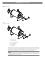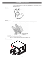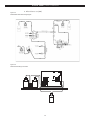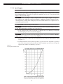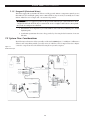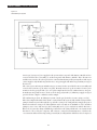
1
Model 9000F Fluoride Analyzer Installation/Operation/Service Manual P/N MAN 9000F Rev B For more information, please contact us: ExpotechUSA 10700 Rockley Road Houston, Texas 77099 USA 281-496-0900 [voice] 281-496-0400 [fax] E-mail: [email protected] Website: www.ExpotechUSA.com A N T E K 9000F | USER’S M A N U A L THIS MANUAL CONTAINS CONFIDENTIAL AND PROPRIETARY INFORMATION… …which is the property of PAC. This manual and all information disclosed herein shall not be used to manufacture, construct, or fabricate the goods disclosed herein; shall not be exploited or sold; shall not be copied or otherwise reproduced in whole or in part and shall not be revealed or disclosed to others or in any manner made public without the express written permission of PAC. REVISION HISTORY Rev Description A First release B Updates to format and content 10.27.04 ii Release Date – October 2004 A N T E K 9000F | USER’S M A N U A L CE DECLARATION OF CONFORMITY Equipment: Fluoride Analyzer Model #: 9000F Date of Issue: April 12, 1996 Manufacturer: Antek Instruments 300 Bammel Westfield Road Houston, TX 77090-3508 USA This equipment complies with the following standards: EN 55011: Limits and Methods of Measurement of Radio Disturbances Characteristics of Industrial, Scientific, and Medical (ISM) Radio-Frequency Equipment IEC 801-2; IEC 1000-4-2; Cenelec 60801-2: Electromagnetic Compatibility for Industrial-Process Measurement and Control Equipment: Part 2: Electrostatic Discharge Requirements IEC 801-3; IEC 1000-4-3; Cenelec 50140: Electromagnetic Compatibility for Electrical and Electronic Equipment: Part 3: Immunity to Radiated, Radio Frequency, Electromagnetic Fields IEC 801-4; IEC 1000-4-4: Electromagnetic Compatibility for Industrial-Process Measurement and Control Equipment Part 4: Electrical Fast Transient/Burst Requirements IEC 801-6; IEC 1000-4-6: Electromagnetic Compatibility for Electrical and Electronic Equipment Part 6: Immunity to conducted disturbances induced by radio frequency fields EN 50082-2; Electromagnetic Compatibility, Generic Immunity Standard: Part 2: Industrial Environment This certifies that the aforementioned equipment conforms with the protection requirements of Council Directive 89/336/EEC on the approximation of the laws of the Member States relating to Electromagnetic Compatibility. Signature of the Manufacturer: Jay Szinyei VP of Research & Development iii A N T E K 9000F | USER’S M A N U A L THIS PAGE INTENTIONALLY BLANK. iv A N T E K 9000F | USER'S MANUAL CONTENTS MATERIAL SAFETY DATA SHEET ELECTRODE FILL SOLUTION .............................................................................. MSDS-1 Section I - Product Identification ........................................................................MSDS-1 Section II – Hazardous Ingredients (Identity Information) ...................................MSDS-1 Section III – Physical Data ..................................................................................MSDS-1 Section IV Fire and Explosion Hazard Data ........................................................MSDS-2 Section V Reactivity Data ..................................................................................MSDS-2 Section VI Health Hazard Data ...........................................................................MSDS-2 Section VII Precautions .....................................................................................MSDS-3 Section VIII – Control Measures ..........................................................................MSDS-3 MATERIAL SAFETY DATA SHEETSHEET RECEIVING ............................................. MSDS-5 Section I – Product Identification .......................................................................MSDS-5 Section II – Hazardous Ingredients .....................................................................MSDS-5 Section III – Physical Data ..................................................................................MSDS-5 Section IV Fire and Explosion Hazard Data ........................................................MSDS-5 Section V Reactivity Data ..................................................................................MSDS-6 Section VI Health Hazard Data ...........................................................................MSDS-6 Section VII – Precautions ...................................................................................MSDS-6 Section VIII - Control Measures ...........................................................................MSDS-7 MATERIAL SAFETY DATA SHEET REAGENT B ...................................................................................................... MSDS-9 Section I - Product Identification ........................................................................MSDS-9 Section II – Hazardous Ingredients (identity Information) ...................................MSDS-9 Section III – Physical Data ..................................................................................MSDS-9 Section IV - Fire and Explosion Hazard Data .....................................................MSDS-9 Section V Reactivity Data ................................................................................ MSDS-10 Section VI Health Hazard Data .........................................................................MSDS-10 Section VII Precautions ...................................................................................MSDS-10 Section VIII – Control Measures ........................................................................MSDS-11 SECTION 1 GENERAL INFORMATION ........................................................................................... 1 1.1 INTRODUCTION ................................................................................................... 1 1.1.1 1.1.2 1.1.3 1.1.4 Principle of Operation ................................................................................................. 1 System Components .................................................................................................... 1 Optional Equipment .................................................................................................... 1 Materials Required But Not Supplied ........................................................................ 1 TOC-1 A N T E K 9000F | USER'S MANUAL 1.2 Requirements ....................................................................................................... 2 1.2.1 1.2.2 1.2.3 1.2.4 1.2.5 Environmental Requirements .................................................................................... 2 Electrical Requirements .............................................................................................. 2 Gas Requirements ........................................................................................................ 3 Plumbing Requirements .............................................................................................. 3 Telecommunication Requirements ............................................................................ 3 SECTION 2 INSTALLATION ........................................................................................................... 5 2.1 Instrument Location ............................................................................................. 5 2.2 Cautions ............................................................................................................... 6 2.3 Physical Installation .............................................................................................. 6 2.3.1 2.3.2 2.3.3 2.3.4 2.3.5 2.3.6 2.3.7 2.3.8 2.3.9 Gases ............................................................................................................................. 6 Installation of Pyrotubes ............................................................................................. 7 Reagent Pump ............................................................................................................ 10 Absorption/Detection Zone ..................................................................................... 10 2.3.4.1 Installing the Ion Specific Reference Electrode ......................................... 11 Dual Head Peristaltic Pump ...................................................................................... 13 Cables .......................................................................................................................... 14 Drain and Vent ........................................................................................................... 15 Computer .................................................................................................................... 15 Solution/Reagent Bottles........................................................................................... 15 SECTION 3 SYSTEM OVERVIEW .................................................................................................. 17 3.1 Introduction ....................................................................................................... 17 3.2 Model 9000F ...................................................................................................... 17 3.3 Computer ........................................................................................................... 22 SECTION 4 ACCESSORY EQUIPMENT .......................................................................................... 25 4.1 Model 735 Controlled Rate Sample Drive ............................................................ 25 4.1.1 4.1.2 Installation .................................................................................................................. 25 Operation .................................................................................................................... 26 4.2 MODEL 734 GAS/LIQUID INLET SYSTEM ............................................................. 27 4.2.1 4.2.2 Installation .................................................................................................................. 27 Operation .................................................................................................................... 27 SECTION 5 PRIMARY TESTS ........................................................................................................ 29 5.1 Pressure/Leak Tests ............................................................................................. 29 5.2 Computer Power-Up ........................................................................................... 29 5.3 Furnace Power Up ............................................................................................. 31 5.4 Reagent Pumps .................................................................................................. 31 5.4.1 5.4.2 Reagent A Pump ........................................................................................................ 32 Reagent B Pump ......................................................................................................... 32 5.5 Installation and Startup Checklist ........................................................................ 32 TOC-2 ANTEK 9000F | USER'S MANUAL SECTION 6 START-UP BASICS ...................................................................................................... 33 6.1 Start-up (for the very first time) ........................................................................... 33 6.2 Obtaining a Stable Baseline ................................................................................ 33 6.3 Building a Calibration Curve .............................................................................. 33 6.4 Running Samples ............................................................................................... 34 6.5 Shutdown .......................................................................................................... 34 SECTION 7 APPLICATIONS & ANALYTICAL PROCEDURES ............................................................. 37 7.1Important Basics .................................................................................................. 37 7.1.1 7.1.2 7.1.3 7.1.4 7.1.5 Gas and Carrier Flows ............................................................................................... 37 Inlet Argon ................................................................................................................. 37 Inlet Oxygen ............................................................................................................... 38 Pyro Oxygen............................................................................................................... 39 Reagent B (Deionized Water) ................................................................................... 40 7.2 System Flow Considerations ............................................................................... 40 7.3 Furnace Temperature ......................................................................................... 42 7.4 Sample Handling & Preparation ........................................................................ 42 7.4.1 7.4.2 7.4.3 Liquid Sample Materials ............................................................................................ 42 Gas and Liquefied Gas (LPG) Sample Materials .................................................... 42 Solid Sample Materials .............................................................................................. 43 7.5 Liquids Analysis .................................................................................................. 43 7.6 Gaseous and Liquefied Gas Analysis ................................................................... 44 7.7 Solids Analysis .................................................................................................... 44 SECTION 8 SOFTWARE .............................................................................................................. 45 8.1 Main Screen ....................................................................................................... 45 8.2 Run Calibration .................................................................................................. 46 SECTION 9 TROUBLESHOOTING ................................................................................................ 51 SECTION 10 PARTS & CONSUMABLES ........................................................................................... 53 10.1 Hardware ......................................................................................................... 53 10.2 Glassware ......................................................................................................... 53 10.2.1 Glassware for use with MultiMatrix (Model 740) ................................................. 53 10.2.2 For use with Gas/LPG Sampling System (Model 734) ........................................... 53 10.3 Consumables .................................................................................................... 53 TOC-3 A N T E K 9000F | USER'S MANUAL THIS PAGE INTENTIONALLY BLANK. TOC-4 MATERIAL SAFETY DATA SHEET ELECTRODE FILL SOLUTION ANTEK 9000F MANUAL Section I - Product Identification Product Name: Electrode Fill Solution Supplier’s Name: PAC Emergency Phone Number: 800-365-2143; 713-580-0339 Address: 300 Bammel Westfield Road, Houston, Texas 77090-3508 Date Prepared: June 1, 2004 Hazardous Shipment Labeling: Testing by Bureau of Explosives has indicated this is not an Oxidizer Section II – Hazardous Ingredients (Identity Information) Hazardous Components: Potassium Chloride (KCl) OSHA PEL .......................... None ACGIH TLV .......................... None LD .......................... 100 mg/Kg, IVNCat De-ionized Water (H20) CAS NO .......................... 7732185 % .......................... 90.0 OSHA PEL .......................... None ACGIH TLV .......................... None LD .......................... 629 mg/Kg, OrlDog Section III – Physical Data Boiling Point: .......................... 100°C Freezing Point .......................... -4°C Specific Gravity .......................... 1.06 Vapor Pressure: .......................... Not applicable pH @ 25°C .......................... 5.5-7.5 Solubility in Water .......................... Miscible Volatiles, % by Wt .......................... Not applicable Evaporation Rate .......................... Not applicable Vapor Density .......................... Not applicable Appearance: .......................... Odorless Liquid MSDS – 1 ANTEK 9000F MANUAL: Material Safety Data Sheets Section IV Fire and Explosion Hazard Data Flash Point .......................... Not applicable Auto Ignition Temperature: .......................... Not applicable Flammable Limits .......................... Not applicable Extinguishing Media: .......................... Any Special Fire Fighting Procedures: ......................... Not applicable Fire and Explosion Hazards: .......................... Not applicable Section V Reactivity Data Stability .......................... Stable Conditions to Avoid .......................... Storing near heat or incompatible chemicals Incompatibilities: .......................... BrF3, anything incompatible with water Hazardous Decomposition Products ..................... None Hazardous Polymerization .......................... will not occur Section VI Health Hazard Data Routes of Entry: Inhalation .......................... No Skin .......................... No Ingestion .......................... Yes Health Hazards: Acute: .......................... Large amounts taken internally may be fatal or cause dizziness, cramps, convulsions, vomiting, weakness, and collapse. Chronic: .......................... can cause anemia, nephritis, and methemoglobinemia Carcinogenicity: Not found Signs and symptoms of exposure: Dizziness, nausea, weakness; no serious acute or chronic affects with either external or inhalation exposure Medical conditions generally aggravated by exposure: kidney or heart problems Emergency and first aid procedures: skin and eyes .......................... wash with large amounts of water for 15 minutes internal .......................... consult physician MSDS – 2 ANTEK 9000F MANUAL: Material Safety Data Sheets Section VII Precautions Steps to be taken if material is released or spilled: Pick up and wash down drain with excess water. Waste Disposal Method: Not regulated. Precautions to be taken in handling and storing: Store at room temperature and keep cap tightly sealed to protect product integrity. NFPA Rating: Scale (0-4) Health .......................... 2 Fire .......................... 1 Reactivity .......................... 0 Specific .......................... None Section VIII – Control Measures Respiratory Protection .......................... Not Applicable Ventilation .......................... Not applicable Protective Gloves .......................... Optional Eye Protection .......................... Safety glasses Other protective clothing .......................... None required Work/Hygienic Practices .......................... Emergency eye wash should be available. Wash hands throroughly before eating or drinking. The information contained herein is furnished without warranty of any kind. Users should consider this data only as a supplement to other information gathered by them and must make independent determinations of the suitability and completeness of the information from all sources to assure proper use and disposal of these materials and the safety and health of employees and customers. MSDS – 3 ANTEK 9000F MANUAL: Material Safety Data Sheets THIS PAGE INTENTIONALLY BLANK. MSDS – 4 ANTEK 9000F MANUAL MATERIAL SAFETY DATA SHEETSHEET RECEIVING Section I – Product Identification Product Name: Receiving Solution Reagent A Supplier’s Name: PAC Emergency Phone Number: 800-365-2143, 281-580-0339 Address: 300 Bammel Westfield Road, Houston, Texas 77090-3508 Effective Date: Jasnuary 1, 2004 Hazardous Shipment Labeling: Testing per NACE (TM 0169) has shown this product to be non-corrosive Section II – Hazardous Ingredients Hazardous Components CAS No % OSHA PEL ACGIH TLV LD Acetic Acid (C. H,02) 64-19-7 1 25 mg/m3 25 mg/ml 1,200 Orl Rbt Sodium Acetate (C2 H 3NaO,) 127-09-3 8 None None 1,300 IVN – Rbt Sodium Chloride (NaCI) 7647-14-5 6 None None 8,000 Orl Rbt Trans 1,2 Diamino Cyclohexane 150 Tetraacetic Acid (CDTA) 482-54-2 <1 None Deionized Water (H 20) 7732-18-5 >84 None 1PR Mouse None 690,000 Orl Dog Section III – Physical Data Boiling Point: .......................... 100°C Freezing Point .......................... -6°C Specific Gravity .......................... 1.07 Vapor Pressure: .......................... Not applicable pH @ 25°C .......................... 5.0-5.5 Solubility in Water .......................... Miscible Volatiles, % by Wt .......................... Not applicable Evaporation Rate .......................... Not applicable Vapor Density .......................... Not applicable Appearance: .......................... Colorless liquid, vinegar-like odor Section IV Fire and Explosion Hazard Data Flash Point .......................... Not applicable Auto Ignition Temperature: .......................... Not applicable Flammable Limits .......................... Not applicable Extinguishing Media: .......................... Carbon dioxide, dry chemical, alcohol foam or mist Special Fire Fighting Procedures: ......................... Use self contained breathing apparatus Fire and Explosion Hazards: .......................... Not applicable MSDS – 5 ANTEK 9000F MANUAL: Material Safety Data Sheets Section V Reactivity Data Stability .......................... Stable Conditions to Avoid .......................... Heat or flame Incompatibilities: .......................... Strong oxidizers (HN03, chromic acid sodium, peroxide), contact with strong caustics can cause spattering Hazardous Decomposition Products: .................... toxic gases, such as carbon monoxide, may be released during a fire. Hazardous Polymerization .......................... will not occur Section VI Health Hazard Data Routes of Entry: Inhalation .......................... No Skin .......................... No Ingestion .......................... Yes Health Hazards: Acute: .......................... Ingestion may cause nausea, breathing difficulties, and damage to stomach and digestive tract. Low hazard for skin and inhalation. Chronic: .......................... can cause anemia, nephritis, and methemoglobinernia Carcinogenicity: Not found Signs and symptoms of exposure: Irritation in respiratory tract, upset stomach, or nausea, irritation of eyes, nose, throat. Medical conditions generally aggravated by exposure: Respiratory ailments, persons with sensitive skin may be affected. Emergency and first aid procedures: skin and eyes .......................... irrigate with plenty of water internal .......................... Dilute with large amounts of water. Do not induce vomiting. Consult physician. Section VII – Precautions Steps to be taken if material is released or spilled: Vacuum up and set aside for waste disposal. Waste Disposal Method: Dilute neutralized solution down drain with excess water. Observe all federal, state, and local laws. Precautions to be taken in handling and storing: Keep away from oxidizers and caustics. Store at room temperature and keep cap tightly sealed. Acetic acid is a CERCL hazard and is subject to Section 3 04 of SARA Title III Other Precautions: Always wash hands thoroughly with soap and water after working with this material. MSDS – 6 ANTEK 9000F MANUAL: Material Safety Data Sheets NFPA Rating: Scale (0 - 4) Health .......................... 1 Fire .......................... 1 Reactivity .......................... 0 Specific .......................... None Section VIII - Control Measures Respiratory Protection .......................... Not Applicable Ventilation .......................... local exhaust Protective Gloves .......................... Yes Eye Protection .......................... Safety Goggles Other protective clothing .......................... Lab coat Work/Hygienic Practices .......................... Emergency eye wash should be available. Wash hands throroughly before eating or drinking. The information contained herein is furnished without warranty of any kind. Users should consider these data only as a supplement to, other information gathered by them and must make independent determinations of the suitability and completeness of the information from all sources to assure proper use and disposal of these materials and the safety and health of employees and customers. MSDS – 7 ANTEK 9000F MANUAL: Material Safety Data Sheets THIS PAGE INTENTIONALLY BLANK. MSDS – 8 MATERIAL SAFETY DATA SHEET REAGENT B ANTEK 9000F MANUAL Section I - Product Identification Product Name: Fluoride Carrier Reagent B Supplier’s Name: PAC Emergency Phone Number: 800-365-2143, 281-580-0339 Address: 300 Bammel Westfield Road, Houston, Texas 77090-3508 Date Prepared: June 1, 2004 Hazardous Shipment Labeling: Testing by Bureau of Explosives has indicated this is not an Oxidizer Section II – Hazardous Ingredients (identity Information) Hazardous Components: Deionized Water (H2O) CAS NO .......................... 100 516 % .......................... 99.95 OSHA PEL .......................... None ACGIH TLV .......................... None LD .......................... 629 mg;/Kg, OrlDog Section III – Physical Data Boiling Point .......................... 100°C Freezing Point .......................... 0°C Specific Gravity .......................... 1.00 Vapor Pressure: .......................... Not applicable pH @ 250C .......................... 5.5-7.5 Solubility in Water .......................... Miscible Volatiles, % by Wt .......................... Not applicable Evaporation Rate .......................... Not applicable Vapor Density .......................... Not applicable Appearance: .......................... Odorless Liquid Section IV - Fire and Explosion Hazard Data Flash Point .......................... Not applicable Auto Ignition Temperature ..................... Not applicable Flammable Limits .......................... Not applicable Extinguishing Media .......................... Any Special Fire Fighting Procedures ............ Not applicable Fire and Explosion Hazards ..................... Not applicable MSDS – 9 ANTEK 9000F MANUAL: Material Safety Data Sheets Section V Reactivity Data Stability ................... Stable Conditions to Avoid ................... Storing near heat or incompatible chemicals Incompatibilities ................... None Hazardous Decomposition Products ................... None Hazardous Polymerization ................... will not occur Section VI Health Hazard Data Routes of Entry: Inhalation ................... No Skin ................... No Ingestion ................... Yes Health Hazards: None Carcinogenicity: Not found on these lists Signs and symptoms of exposure: No serious acute or chronic affects with either external or inhalation exposure Medical conditions generally aggravated by exposure: None Emergency and first aid procedures: skin and eyes .......................... wash off with large amounts of water for 15 minutes internal .......................... induce vomiting, consult physician Section VII Precautions Steps to be taken if material is released or spilled: Wash down drain with excess water. Waste Disposal Method: Vacuum and/or wash down drain with excess water. Observe all federal, state, and local laws. Precautions to be taken in handling and storing: Store at room temperature and keep cap tightly sealed to protect product integrity. NFPA Rating: Scale (0-4) Health .......................... 1 Fire .......................... 1 Reactivity .......................... 0 Specific .......................... None MSDS – 10 ANTEK 9000F MANUAL: Material Safety Data Sheets Section VIII – Control Measures Respiratory Protection .......................... Not Applicable Ventilation .......................... Not applicable Protective Gloves .......................... None Eye Protection .......................... Safety Glasses Other protective clothing ........................ None Work/Hygienic Practices ......................... Emergency eye wash should be available. The information contained herein is furnished without warranty of any kind. Users should consider these data only as a supplement to other information gathered by them and must make independent determinations of the suitability and completeness of the information from all sources to assure proper use and disposal of these materials and the safety and health of employees and customers. MSDS – 11 ANTEK 9000F MANUAL: Material Safety Data Sheets THIS PAGE INTENTIONALLY BLANK. MSDS – 12 A N T E K 9000F | U S E R ' S M A N U A L SECTION 1 GENERAL INFORMATION 1.1 INTRODUCTION The Antek 9000F Fluoride Measurement System is a powerful development for rapid analysis of materials containing fluoride compounds. Solid, liquid, gaseous, or LPG samples may be analyzed with ease usually in less than fifteen minutes. 1.1.1 Principle of Operation The automated method of analysis involves a high temperature oxidation of the entire sample, converting any fluorine containing compounds to hydrogen fluoride (HF). The HF then preferentially reacts with a proprietary carrier and is then transferred to a buffered receiving solution in which it is decomplexed. The Fluoride Ion (F-) is then measured in a temperature controlled manner with an Ion Specific Electrode (ISE). Since the fluoride induced millivolt change is proportional to the amount of fluoride in the sample, quantitation is greatly simplified. The chemical reactions involved may be summarized as follows: Reaction Chemistry by Pyrohydrolysis ISE RF + H 0 + 0 ∆ HF + Oxides 2 2 HF + Buffers NaF + H 20 Detection as disassociated F- ions by ISE 1.1.2 System Components Basic System: Model 9000F Fluoride Analyzer Accessories for liquid analysis Computer System with Integrated software Package Starter Chemicals and Reagent Storage Rack 1.1.3 Optional Equipment Model 735E Syringe Drive Model 734 Gas/LPG Inlet System Model 738 Autosampler Model 740 MultiMatrix NOTE: Installation and use of the Basic System are covered in this manual. Installation and use of other optional equipment will be covered in other manuals or addenda to this manual. 1.1.4 Materials Required But Not Supplied In order to install and operate the System 9000F, the following additional materials are required: • • • • • • • • Small set of screw drivers Small set of open end wrenches including 7/16", 1/2", and 9/16" Small adjustable wrench Needle nose pliers Argon or Helium supply, dry, regulated to 40 psig Oxygen supply, dry, regulated to 40 psig Flow meter to measure up to 750 cc/min. One narrow mouth, plastic, liquid waste storage container 1 A N T E K 9000F | U S E R ' S M A N U A L CAUTION: Become familiar with all modules and accessories and carefully read all instructions before attempting to operate the system. 1.2 Requirements 1.2.1 Environmental Requirements 1. Ambient Temperature - Operational stability requires a reasonably constant room temperature. 2. Corrosive or Dusty Atmosphere - A corrosive atmosphere will in time cause problems with solder joints, electrical contacts. Dust and dirt that may be swept in by cooling fans may collect and retain moisture thus causing corrosion and short circuits. Dust may also collect on heat transfer surfaces causing reduced radiation and resulting in component damage. 3. Space Requirements - Approximately 72 inches (183 cm) x 30 inches (76 cm) of bench space is required for the Fluoride System. The bench should be capable of supporting at least 350 pounds (159 kg). Adequate air space should be provided on both sides, top and behind the instrument. 4. Ventilation/Flammables - Reasonable ventilation associated with a “typical” modern laboratory environment is normally acceptable. WARNING: Furnace operates at a temperature in excess of 1000°C and can serve as an ignition source. 5. Fluid Drain - Plumbing the waste line directly to a drain is preferred. However, an unbreakable plastic container is recommended for the collection of waste fluids if plumbing to a drain is not possible. Place waste container where it can be easily monitored at a level below the Model 9000F Analyzer. NOTE: These aqueous waste materials are high in salt content. Routine disposal with water dilution is permissible if compatible with your laboratory sewer system and local regulations. 1.2.2 Electrical Requirements The Antek Model 9000F Fluoride System and computer utilizes stable 115 VAC, 50/60 Hz or 230 VAC, 50 Hz. A 15 amp circuit is required for 115 VAC and an 8 amp for 230 VAC. A good ground is necessary for each component. The basic system requires seven (7) electrical outlets. Check Optional Equipment for additional electrical requirements. WARNING: A poor ground may present a severe shock hazard. 115 VAC Amperes 230 VAC Amperes Outlets Required Model 734 2.0 1.0 1 Model 735 1.0 0.5 1 15.0 8.0 1 Model 9000F Computer System 2 Circulating Baths 1 Peristaltic Pumps 1 2 A N T E K 9000F | U S E R ' S M A N U A L 1.2.3 Gas Requirements Chromatographic grade argon and chromatographic grade oxygen are required to operate the Antek Model 9000F Fluoride System. These gas streams must be regulated at 40 psig and in-line gas dryers are suggested. Oxygen ........................................ 3.0 bar (40 psig), 99.75%, maximum moisture 5 ppm Argon ........................................... 3.0 bar (40 psig), 99.75%, maximum moisture 5 ppm Helium may be substituted for argon as a carrier gas. 1.2.4 Plumbing Requirements Dual Stage Regulators provide stable pressures that do not vary from day to day and help provide consistent and reproducible results. 1.2.5 Telecommunication Requirements • Telephone jack suitable for use in FAX/modem service • PCAnywhere32 software 3 A N T E K 9000F | U S E R ' S M A N U A L THIS PAGE INTENTIONALLY BLANK. 4 A N T E K 9000F | U S E R ' S M A N U A L SECTION 2 INSTALLATION 2.1 Instrument Location Position the Antek 9000F Fluoride Analyzer, computer, and accessories on a level surface as shown in the following figures. Alternate arrangements are possible. Consult this Operator’s Manual or your local Antek Representative. Waste fluids can be collected in one single container or plumbed directly to a drain. Figure 2.1 Model 9000F with Model 735 Figure 2.2 Model 9000F with Model 740 9000F Figure 2.3 Model 9000F with Model 734 5 A N T E K 9000F | U S E R ' S M A N U A L 2.2 Cautions WARNING: The furnace of the Antek 9000F Fluoride Analyzer operates at temperatures above 1000ºC and can serve as an ignition source. The instrument must be located in a nonexplosive atmosphere. WARNING: Do not power up equipment. All activities described in Section 2 - Installation do not require electrical power. 2.3 Physical Installation 2.3.1 Gases Connect gases as shown in Figure 2.4. Figure 2.4 Gas Connections Using the copper gas lines supplied with the 9000F system, connect the supply gases to the proper gas inlet fittings. Refer to Figure 2.6a for the recommended assembly procedure for the swage - type compression fittings included in the accessory kit. Figure 2.5a Compression Fittings Insert tubing through nut. Slide ferrule over tubing. Insert tubing with ferrule until tubing bottoms in fitting. Secure nut finger-tight plus one turn. 6 A N T E K 9000F | U S E R ' S M A N U A L Figure 2.5b Glass to Metal Fitting Position ¼” nut first, then slide Teflon® ferrule over glass arm. Insert male fitting until glass arm bottoms out in base of male fitting. Secure finger-tight. Back out glass arm tip I mm so that bevel inside male fitting does not chip glass arm tip. Tighten until male nut threads are nearly covered. Do not over tighten. 2.3.2 Installation of Pyrotubes To install the pyrolysis tube, remove the side panels. To remove the side panels, loosen the four locking screws located on each panel and remove side covers by lifting straight up with the panels as shown in Figure 2.6. If necessary, the instrument cover may be removed by loosening the two locking screws and sliding back one-inch and lifting up. Figure 2.6 CAUTION: Remove the right panel slowly so that accidental breakage of the pyrolysis tube (if present) will not occur. 7 A N T E K 9000F | U S E R ' S M A N U A L Figure 2.7 Pyrotube 71156 Installation Figure 2.8 Pyrotube 71191 Installation 1. Receiving vessel 2. Ceramic endplates 3. Pyro oxygen gas fitting 4. Reagent B fitting 5. Inlet gas fitting 6. Spring Clamp The following is a step-by-step procedure for the installation of the P/N 71156 pyrotube. This pyrotube is intended for the analysis of gas and liquid samples only. This pyrotube may be used in conjunction with microliter syringes, Model 734 Gas/Liquid Inlet System, or Model 735 Sample Drive. Refer to Figure 2.6 and Figure 2.7 for access, location, and orientation information. NOTE: It may be desirable to perform a SAVE file information as described in Section 8 before system shutdown. This will preserve all analytical parameters, calibration data, and sample data for later use or reference. 8 A N T E K 9000F | U S E R ' S M A N U A L In the event a P/N 71156 pyrotube needs to be installed or replaced, the following steps should be taken: 1. To allow the furnace to cool, turn the main power switch of the 9000F Furnace Module to the OFF position, and unplug the power cord from the power source. WARNING: Ensure that the power cord has been unplugged from the power source before continuing. If power is applied while servicing internal components, a severe electric shock hazard may exist. 2. Remove the side panels as shown in Figure 2.6. This should provide adequate space for installation of the pyrotube. 3. If a pyrotube is currently installed in the furnace, carefully remove the receiving vessel, remove the gas fittings, remove the spring clamp, loosen the ceramic endplates, and remove the used pyrotube. 4. Ensure that the furnace is free of any materials which will obstruct the insertion of the new pyrotube. 5. Carefully clean the exterior of the new pyrotube with fluoride-free high-purity isopropyl alcohol to remove any materials which may damage the tube when heated. 6. Dry the tube completely, taking care not to touch the pyrotube, as fingerprints can leave oils that will damage the tube when heated. 7. Insert a new septum into the pyrotube with the Teflon® side in. 8. Remove o-ring (if present) from the new pyrotube and carefully insert the pyrotube into the right side of the furnace as shown in Figure 2.7. 9. Install the ceramic endplates as illustrated in Figure 2.7 and secure with the spring clamps on both ends of the furnace. 10. Adjust the orientation of the pyrotube as illustrated in Figure 2.7 or 2.8. WARNING: The proper attachment of the gas inlet tubes (side arms) is critical. If not hooked up properly, an explosion hazard may exist. 11. Locate and attach the inlet gas line (from outside the rear panel) and the pyro oxygen line (from the flow meter assembly inside the front panel) to the proper pyrotube side arms with ¼” nuts and Teflon® ferrules. 12. Locate and attach the Reagent B feedline to its inlet as shown in Figure 2.7 or 2.8. CAUTION: Care should be taken when assembling the metal/Teflon®/quartz connections. The quartz tube is fragile and may be broken easily. See Figure 2.5. 13. Replace the o-ring seal and install the receiving vessel on the left (exit) side of the pyrotube and secure with the joint clamp. 14. Ensure that all gas connections are correct and properly fitted. 15. If replacing a used pyrotube, conduct a leak test as described in Section 5 before resuming normal operations. During initial start-up installation, a leak test will be performed later in Section 5. 9 A N T E K 9000F | U S E R ' S M A N U A L 2.3.3 Reagent Pump Locate and inspect the Reagent B Pump as described in Figure 2.9. Figure 2.9 Reagent Pump Make sure that the connections of the tubing leading to and from the Reagent B Pump are secure and tight. 2.3.4 Absorption/Detection Zone Open the front door of the Antek Model 9000F Fluoride analyzer by loosening the two locking screws on the door and it will open outward to the left as shown in Figure 2. 10. Figure 2. 10 Door Open 9000F 10 A N T E K 9000F | U S E R ' S M A N U A L The Front Panel is shown in Figure 2. 11. Figure 2.11 Chemistry Section Locate the Ion Specific Electrode (ISE) flow cell as shown in Figure 2.11. 2.3.4.1 Installing the Ion Specific Reference Electrode 1. Locate and remove the Reference Electrode (P/N 71315) from the 9000F Accessory Kit. The electrode is stored in a protective holder with a moist sponge to keep it from drying out. Figure 2.13 Reference Electrode 2. Remove and inspect the Reference Electrode for damage, particularly the membrane which forms the sensing end of the Electrode Body. 3. If the level of Potassium Chloride (KCI) Solution is low and/or has a bubble of air in it larger than 0. 1 ml, remove the Electrode from its body and fill with the provided Potassium Chloride (KCI) Solution (P/N 37120) as shown in Figure 2.13. 11 A N T E K 9000F | U S E R ' S M A N U A L Figure 2.13 Filling Reference Electrode 4. Carefully insert the Reference Electrode into the ISE Cell Body and finger tighten. Figure 2. 14 Installing Reference Electrode 5. Carefully place the Sensing Electrode (P.N. 71314) into the ISE Cell Body (snap into place) and finger tighten the nut. Figure 2. 15 ISensing Electrode 12 A N T E K 9000F | U S E R ' S M A N U A L 6. Connect the ISE Sensing Electrode (P.N. 71314), the ISE Reference Electrode, and ground as shown in Figure 2.16. Figure 2.16 ISE Flow Call Figure 2.17 ISE Cell Body Flow Path 7. Make sure the Receiving Solution flowpath is clear as shown in Figure 2.17. 2.3.5 Dual Head Peristaltic Pump Locate the Dual Head Peristaltic Pump as shown in Figure 2.18. Figure 2. 18 Dual Head Peristaltic pump 900 0F 13 A N T E K 9000F | U S E R ' S M A N U A L Confirm that the Peristaltic tubing (P.N. 30258) is properly locked in position as shown in Figure 2.19. Figure 2.19 Peristaltic Pump Tubing 2.3.6 Cables Install the Control Interface connections as shown in Figure 2.20. Power cords may be attached to equipment. CAUTION: Do not apply power. See Section 2.3.8 regarding computer. Figure 2.20 Control Interface Connections 14 A N T E K 9000F | U S E R ' S M A N U A L 2.3.7 Drain and Vent Install the drain and vent as shown in Figure 2.2 1. Waste fluids can be collected in one single container or directly plumbed to a drain. Figure 2.21 Drain and Vent 2.3.8 Computer Install the computer, monitor, keyboard, and mouse interface as described in the computer’s Operator’s Manual and as shown in Figure 2.20. Follow closely the guidelines set out in the computer’s Operator’s Manual. 2.3.9 Solution/Reagent Bottles Fill and install the Reagent Bottles as shown in Figure 2.22. WARNING: Severe damage will be caused to the Model 9000F if incorrect solutions are used. Check all labels prior to filling of the Reagent Bottles. Figure 2.22 Installing Reagent Bottles 15 A N T E K 9000F | U S E R ' S M A N U A L THIS PAGE INTENTIONALLY BLANK. 16 A N T E K 9000F | U S E R ' S M A N U A L SECTION 3 SYSTEM OVERVIEW 3.1 Introduction Before installing accessory equipment and/or proceeding to the primary testing section of the installation procedure, become familiar with the locations and various features of the Antek Model 9000F Fluoride Analyzer. Figure 3.1 System Overview 3.2 Model 9000F Figure 3.2 Access points To remove instrument panels, loosen the two locking screws, slide the top cover back one inch, lift up on the cover, and set the cover aside. Next, loosen the four locking screws located on each of the side panels and remove side covers by lifting straight up with the panels. CAUTION: Remove the right panel slowly so that accidental breakage of the pyrolysis tube will not occur. 17 A N T E K 9000F | U S E R ' S M A N U A L Figure 3.3 Model 9000F Front Panel 9000F To open the front door. Loosen the locking screws and the door will hinge out of the way. Figures 3.4-3.11 provide an instrument overview. Figure 3.4 Model 9000F Chemistry Section 1. Sub-Panel Access Screws (5) 2. Furnace Temperature Controller 3. Flowmeters a. Oxygen To Pyrolysis Tube b. Oxygen To Pyrolysis Inlet c. Argon To Pyrolysis Inlet 18 A N T E K 9000F | U S E R ' S M A N U A L 4. Fluoride Detector (ISE) Figure 3.5 Model 9000F General Plumbing Diagram Figure 3.6 Rear Panel Plumbing Connections 19 A N T E K 9000F | U S E R ' S M A N U A L Figure 3.7 Pyrolysis Tube Plumbing (gas/liquid only) Figure 3.8 Rear External View 11 12 10 1 3 2 5 7 4 } 9 8 6 7 1. Oxygen/Argon Mix - Feeds carrier mixture to pyrotube 2. Reagent B Feed - supplies Reagent B to the Reagent B Pump 3. Power Switch - applies power to 9000F 20 A N T E K 9000F | U S E R ' S M A N U A L 4. Power Connection - links power cord 5. Fuse Tray containing: Fuses Fuse Rating 115 v Ll L2 Fuse Rating 230 v 15 amp 15 amp 6. Fans and Peristaltic Pump Transformer 8 amp 8 amp 1 amp Power Supplies 1 amp Furnace Controller 1 amp Furnace 12 amp 7. Drains - waste exit to containers (2) 8. Carrier Supply - argon or helium 9. Oxygen Supply 10. Reagent A - from Reagent A supply bottle 11. Computer Interface - 50-pin ribbon cable 12. Remote Control Cable Connectors for Model 734/735 Figure 3. 9 Model 9000F Rear Internal View 1. 5B Board 2. Computer Interface Board - Ribbon Cable Distribution Board 3. Ribbon Cable Connection from Computer 4. Reagent A Feed - supplies Reagent A to Valve A 5. Gas Supplies - gases to flowmeters 6. Waste Connections - to waste bottles 7. Fans 8. Rear Panel Main Board - power distribution 9. Reagent B Input - supplies Reagent B to Reagent B Pump 21 A N T E K 9000F | U S E R ' S M A N U A L Figure 3. 10 Model 9000F Pan 1. Fans 2. Furnace - Oxidation Furnace 3. Dual Head Peristaltic Pump - pumps Receiving Solution A into the Receiving Vessel and out to Rear Panel Waste 4. Furnace Controller - controls furnace temperature 5. 5 VDC Power Supply - supplies voltage to signal boards and SSRs Figure 3.11 Model 9000F Sub-pan Rear View 1. Relay Output Board Controls Model 734/735 2. Detector Board - converts Reference and Sensing Electrode signals for computer 3. Flowmeters and Connections - controls gases to pyrolysis tube 4. Furnace Temperature Controller Connector - operates 12" combustion furnace 22 A N T E K 9000F | U S E R ' S M A N U A L 3.3 Computer NOTE: See computer Operator’s Manual for more detail. Figure 3.12 Rear View The computer mouse (Figure 3.13) controls the screen pointer or cursor. Cursor shapes include I-beam, arrow, and hand. Figure 3.13 Mouse Main Operator Button Right Button There are four basic mouse techniques: Pointing Position the cursor Clicking Activating/Selecting Double Clicking Dragging Highlights and opens the file Selecting and repositioning an icon to a new location 23 A N T E K 9000F | U S E R ' S M A N U A L THIS PAGE INTENTIONALLY BLANK. 24 A N T E K 9000F | U S E R ' S M A N U A L SECTION 4 ACCESSORY EQUIPMENT The Antek 9000F Fluoride Analyzer utilizes several accessories to enhance overall performance. This section contains guidelines that can be used along with the Operator’s Manuals for the following equipment. 4.1 Model 735 Controlled Rate Sample Drive The Model 735 Controlled Rate Sample Drive provides an accurate, reproducible method of sample introduction into the furnace of the ANTEK 9000F system. The Model 735 may be used in conjunction with a syringe for liquid or with a Model 740 MultiMatrix and a quartz sample boat for liquid and solid samples. See the Model 735 Operations Manual for detailed instructions before attempting to operate the inlet system. 4.1.1 Installation The Model 735 should be located on the right side of the ANTEK 9000F system. Depending on the configuration of the 9000F system and the pyrotube being used, the Model 735 may be interfaced differently. Figures 4.1 and 4.2 illustrate two common interface configurations and physical layouts. Figure 4.1 Interface to 71156 Direct Injection 9000F MODEL 735 SAMPLE DRIVE Figure 4.2 Interface to Multi•Matrix using PIN 71191 Pyrotube 9000F MODEL 735 SAMPLE DRIVE In order to install the Model 735, the following guidelines should be followed: 1. Locate the Model 735 as shown in Figure 4. 1 or 4.2. 2. Attach all electrical power and electronic connections. Refer to Figure 4.3 for the location of all controls and connections. 3. To have the 9000F control the movement of the Model 735, utilize the Remote Control Cable, P/N 20058. Connect the five prong adaptor to the Remote Inlet on the Model 735 rear panel. Connect the plug to the desired External Timed Events port on the 9000F rear panel. 25 A N T E K 9000F | U S E R ' S M A N U A L Figure 4.3 Model 735 Front & Rear Panel Connections MODEL 735 SAMPLE DRIVE 4.1.2 Operation Once the Model 735 is properly installed, the following steps should be taken to place the system in service: 1. Place the main power switch in the ON position. 2. Allow the Model 735 to stand, with the power ON, for at least five minutes to ensure accurate drive speeds. 3. Drive the push block in the forward and reverse directions using the forward and reverse pushbuttons and the speed control. At this point, the forward and reverse stop positions may be adjusted using the knob adjustments on the left and right sides of the Model 735 rear panel. NOTE: For use with a microliter syringe, the forward stop should allow the push block to completely eject all liquid from the syringe; and the reverse stop should allow the push block to be in a position as to not interfere with the syringe. For use with a quartz boat, the forward stop should allow the push block to completely insert the boat into the furnace; and the reverse stop should position the boat under the septum of the pyrotube or the access port of the multi-matrix sampler. 4. Consult the 735 Operator’s Manual for a complete review of installation procedures. 5. Ensure that the 9000F system can control the Model 735 and that all necessary timed events have been programmed. 6. Section 5 Primary Tests of this manual contains a testing procedure to confirm control of the Model 735. 26 A N T E K 9000F | U S E R ' S M A N U A L 4.2 MODEL 734 GAS/LIQUID INLET SYSTEM The Model 734 Gas/Liquid Inlet System is intended for the introduction of gases and liquefied petroleum gases into the furnace of the ANTEK 9000F system. The Model 734 is available in different configurations for various analytical requirements: Model Description 734-1 ............................................. Gas/liquefied gas sampling system 734-1 A .......................................... Automated gas/liquefied gas sampling system 734-2 ............................................. Gas sampling system 734-2A ........................................... Automated gas sampling system 734-3 ............................................. Liquefied gas sampling system 734-3A ........................................... Automated liquefied gas sampling system The following text will focus on the general aspects of installation and operation. For complete details of Model 734 installation and operations, refer to the Model 734 Operations Manual. 4.2.1 Installation Depending on the configuration of the 9000F system and the pyrotube being used, the Model 734 may be interfaced differently. Figure 4.4 illustrates a common interface configuration. Figure 4.4 Interface to 71156 Direct Injection 9000F 4.2.2 Operation Once the Model 734 is properly installed, the following steps should be taken to place the system in service: 1. Place the main power switch to the Model 734 in the “ON” position. 2. Allow the Model 734 to warm up for at least ½ hour prior to sample injection. 3. Using the appropriate Model 734 controls, assure that the valves are fully functional. 27 A N T E K 9000F | U S E R ' S M A N U A L THIS PAGE INTENTIONALLY BLANK. 28 A N T E K 9000F | U S E R ' S M A N U A L SECTION 5 PRIMARY TESTS 5.1 Pressure/Leak Tests The following procedure will only apply if there are no other instruments using the same gas supply. 1. Turn all flow meter control needle valves clockwise to zero. CAUTION: Do not force valve closure as damage to flow meter can occur. Turn clockwise only until slight resistance is felt. 2. Apply pressure (40 psi) to instrument by turning the gas on at the oxygen cylinder regulator. Pressure will be seen on the regulator. 3. Turn off the cylinder valve and ensure that the pressure does not drop. 4. If the pressure does not drop, there are no leaks between the regulator and the instrument. If pressure does drop, check all fittings between the gas supply outlet and the flow meters. Repeat procedure for Argon (or Helium). Once the pressure test has been completed successfully, an instrument leak check must be performed. 1. Reduce the oxygen supply to <5 psi either at the cylinder regulator or with an in-line regulator. 2. Ensure that there is a septum in the injection port of the pyrotube or the Model 740 MultiMatrix. 3. Open the Pyro O2 flow meter to half of full scale. 4. Plug both the gas vent and the liquid vent on the back of the instrument. 5. If there are no leaks, the ball in the flow meter will fall to zero. If it does not drop, check all fittings to ensure that they are tight and secure. Fittings to check include: a. Pyrotube ball joint O-ring and receiving vessel clamp b. Pyrotube c. Reducing union for Reagent B inlet tubing d. Reducing union for Carrier gas inlet tubing e. Septum 6. Once the system is deemed leak-free, remove plugs, adjust regulator to 40 psi and return flow meters to desired settings. 5.2 Computer Power-Up Before proceeding with further testing, it will be necessary to activate the computer control system. WARNING: The computer “Assembly and Installation” procedure located in the Quick Setup pamphlet of the computer’s installation package must have been completed before proceeding with the section. Turn on the power to the CPU and monitor. After the computer has gone through its start up routine, double click on the 9000F icon on the desktop to initialize the Fluoride software. The screen in Figure 5.1 will come up as shown. 29 A N T E K 9000F | U S E R ' S M A N U A L Figure 5.1 Initial Screen with Standby Dialog Box Opened The Standby Dialog Box will appear. If the furnace and the cooler temperatures are ±10% of the preset temperature noted in the loaded method, a green status bar will be shown. If not, a red status bar will be displayed. Press OK to close the dialog box. The Main Screen will now be accessible as seen in Figure 5.2. Using the mouse, one of three function screens can be selected: Edit Method, Run Calibration and Run Sample. Figure 5.2 Main Screen 30 A N T E K 9000F | U S E R ' S M A N U A L 5.3 Furnace Power Up WARNING: Furnace operates at a temperature in excess of 1000ºC and can serve as an ignition source and cause severe burns. To heat the combustion furnace, perform the following steps. The furnace controller is located on the front panel of the Antek 9000F. NOTE: The furnace controller contains no user serviceable parts. Warranty is void if controller shows evidence of tampering. Figure 5.3 Furnace Controller Action Result 1. Press * to view setpoint 2. Press * % to increase setpoint 3. Press * % to decrease setpoint 4. Adjust for a setting of 1050ºC. 5. Press %% together to reset alarm or reset fault message 6. If alarm persists, discontinue operations and disconnect power. Contact local Antek Representative or Antek Service Department. 7. Note the temperature indication of the furnace as it heats to verify proper operation. 5.4 Reagent Pumps CAUTION: Do not allow the pumps to operate without a filled reagent bottle being attached. Running the pump dry for extended periods of time can cause the pump to fail and can cause damage to the pyrolysis tube if an injection occurs without Reagent B being present in the pyrotube. 31 A N T E K 9000F | U S E R ' S M A N U A L 5.4.1 Reagent A Pump Reagent A (TISAB) is added to the receiving vessel via a Masterflex dual-head peristaltic pump found on the left hand side of the Antek 9000F. Make sure that a bottle containing TISAB is connected to the Reagent A port. Turn on the flow at the drive controller by setting the switch to FWD and the speed to 3.0. Verify that flow is advancing from the bottle to the receiving vessel, through the ISE and out the liquid vent. 5.4.2 Reagent B Pump CAUTION: The Reagent B pump should not be turned on until the furnace is at least 800ºC. Reagent B is introduced to the pyrotube via a Masterflex peristaltic pump. Turn the Reagent B pump switch on (on is the up position, the middle position is off). Turn the speed dial to the 3 o’clock position for a rate of 1 ml/min. Visually ensure that Reagent B is being pumped to the entrance of the pyrotube. 5.5 Installation and Start-up Checklist The following is a checklist that can be used to assure that the Model 9000F is ready to enter routine operation. ______ System located properly? ______ Accessories (if any) installed? ______ Gas lines with specified pressures and flows installed? ______ Waste line and vents installed? ______ Pyrotube properly installed? ______ Leak check pressure check performed? ______ Reagent reservoirs filled and pumps primed? ______ Furnace at operating temperature? ______ Computer operational with integrated software? 32 A N T E K 9000F | U S E R ' S M A N U A L SECTION 6 START-UP BASICS This chapter contains a detailed description of the procedures needed to establish basic operation upon instrument start-up. CAUTION: Do not attempt to operate the Model 9000F system until all installation and setup procedures outlined in the previous sections of this manual have been successfully completed. CAUTION: Become familiar with the location and use of all controls, indicators, connections, and accessories and carefully read all instructions prior to operating any portion of the system. 6.1 Start-up (for the very first time) To power up the instrument (for the first time, or when power has been lost): It is important to follow this start-up procedure step-by-step. You are establishing communication between the instrument, peripherals, and the PC. 1. Turn on the 9000F instrument first. The on/off switch is on the back of the instrument, located in the lower right-hand comer (as you look at the front of the 9000F). 2. Turn on any peripherals (735, 734 or 740). 3. Turn on the computer. Start the Fluoride software. 6.2 Obtaining a Stable Baseline 1. Turn on the gases (argon or helium and oxygen). Set the rotometers to 4.0, 3.0, and 2.0 on the front panel of the instrument. (Flows may be sample dependent.) 2. Turn on the flow of TISAB (Reagent A) on the separate drive controller. Set this switch to FWD. 3. Set the furnace controller to 1050°C. This procedure is described in detail in Section 5.3. 4. Turn on the Reagent B pump (up is the on position, the middle position is off) after the furnace reaches 800ºC. 5. Let the instrument equilibrate. Load the calibration file and the method file you want to use with your samples. To do this, enter edit method and open the file you wish to use. Method files have “.mth” file extensions and are saved under c:\9000f\methods directory. Go to Run Calibration screen and open the calibration file you want to use, or if you want to create a new calibration curve, see the next section. 6.3 Building a Calibration Curve 1. Select “Run Calibration” from the Main Screen. 2. Press Edit and press “New” and name this file. Select your display preferences by pressing display preferences under the Edit button. Be sure to save this new cal file once you have created it. The calibration files are saved under c:\9000F\cals directory. Calibration files all have the “.cal” extension after their file name. NOTE: A detailed description of software operation is given in Section 8. 3. Press File and select Save File As. Type in the name with the “.cal” extension and then press OK. 33 A N T E K 9000F | U S E R ' S M A N U A L 4. Run a few blanks to be sure that the baseline is quiet and stable. You can include this data in the calibration if you choose. NOTE: Avoid cross contamination. Be sure to clean the syringe out thoroughly. Draw a sample with the syringe the same way each and every time. This ensures good precision. 5. To run a standard, select the Run menu. Press Standard. Fill out the information about the standard completely and correctly. For example, if you were using a 1 ppm organic fluoride, enter 1 ppm F std as the name, enter the volume you are going to inject (20 µL), and then enter 1 for the concentration amount. Draw 20 µL of a fluoropentane in xylenes or similar organic standard into a syringe. Place the syringe through the septa and mount it onto the Model 735 Controlled Syringe Drive or in a quartz boat in the Model 740 multi-matrix. The Fluoride software sends a signal to the Model 735 Controlled Rate Syringe Drive after you press OK. The analysis begins when the OK button is pressed. At each level of the calibration, do multiple injections. To run another injection right after the other (another injection of the same sample), press Run, and select Standard and highlight the sample you are injecting again. Press Insert After. This sample is labeled with the same name followed by a dash and a number. The numbers denote the individual injections. 6. To use or not use a particular injection, press Edit. Select Name’s, I.D.s and Uses, and highlight the particular injection to use or not use. To not use this injection, click on the green X box. This clears that box and this data will not be included in the calibration calculations. To use a particular injection, be sure that the green X box is activated. (You will see a green box with an X in it). 6.4 Running Samples 1. Be sure that the calibration curve that you want to use is loaded. To be sure of this, click on Run Calibration and be sure your calibration curve appears. If it does not use the File and Open commands to load the correct curve. 2. Click on Run Sample. 3. In this menu, click on Run and then Sample. Fill out the information regarding the sample completely and correctly. Be sure to enter “1” for Multiplication/Dilution Factor and enter a Sample Weight (or Volume). 4. The analysis begins once you press OK. The data is collected and when the analysis is complete, the baseline is drawn, the maximum mV is noted and the area counts displayed. When the run is finished, click OK and this data will now be displayed on the sample table. If you do not want to save the data, click on cancel and abort the run. 5. Be sure to save the file once you have all your data displayed in the sample table. The file names have “.sam” extensions. They are saved in the c:\9000f\samples directory. 6.5 Shutdown Daily Shutdown Procedure: 1. Turn off the Reagent B. 2. Turn off the flow of TISAB (Reagent A) on the drive controller. 3. Turn off the gases at the rotometers. Carefully turn these knobs clockwise to turn off the flow of gases. 4. Turn off the monitor only. Leave the PC on. 34 A N T E K 9000F | U S E R ' S M A N U A L To shutdown the instrument for a long period of time: 1. Turn off the Reagent B pump. 2. Turn down the furnace to 500°C. 3. Turn off the gases at the rotometers. Carefully turn these knobs clockwise to turn off the flow of gases. 4. Turn off the flow of TISAB (Reagent A) on the drive. Take the bottle cap and line that are affixed and inside the TISAB gallon reservoir and affix it to a gallon jug filled with high purity de-fluorinated water (ASTM Type I water). Turn the dual head peristaltic pump on and flush the instrument lines out with water. Flush at least a half of a gallon through the instrument. When you are through, turn off the flow of water to the instrument. The middle position on the controller is OFF. 5. Exit the fluoride software. Turn off the PC and monitor. 6. Turn off any peripherals. 7. Turn off the 9000F. 35 A N T E K 9000F | U S E R ' S M A N U A L THIS PAGE INTENTIONALLY BLANK. 36 A N T E K 9000F | U S E R ' S M A N U A L SECTION 7 APPLICATIONS & ANALYTICAL PROCEDURES The Antek 9000F is capable of rapid, precise, quantitative analysis of fluorine content in solid, liquid, or gaseous matrices. This section will attempt to provide the Antek 9000F user with a broad spectrum of information on the finer details of various recommended analytical procedures and instrument applications. Included are procedures and suggestions with particular emphasis on gas flows, furnace temperature, sample handling and preparation, calibration, and sample analysis. NOTE: The following procedures and suggestions are meant for informational purposes. The optimum parameters and procedures for any particular application and sample type will best be determined by experience or consultation with ANTEK applications specialists. CAUTION: Do not attempt to operate the system until all of the setup procedures set forth in the previous sections of this manual have been thoroughly read, understood, and completed. 7.1 Important Basics Regardless of the application in which the Antek 9000F is employed, there are certain conditions that must be present in order to obtain predictable analytical performance. It is also important that the operator understand the basic principles and instrument functions utilized. 7.1.1 Gas and Carrier Flows WARNING: High pressure gases should be handled with extreme care. Ensure that all relevant safety precautions are carefully followed and all gas lines, regulators, gas purifiers, etc. are specified for the intended use. 7.1.2 Inlet Argon Argon or helium is used as a carrier gas to sweep the volatilized sample from the inlet and into the high temperature, oxidative portion of the pyrotube. Normally, 75 to 140 mL/min argon flow is required to provide an even sweep of the sample inlet. Helium is also acceptable. NOTE: OTE: For certain applications, inlet argon may not be necessary or desirable. In these cases, proceed to Section 7.1.2 - Inlet Oxygen. 1. Turn OFF (clockwise) all gas control valves. CAUTION: Do not shut control valve off hard. Turn clockwise only until slight resistance is felt. Over-tightening may damage the control device. 2. Set the supply pressure of the argon to the recommended level as outlined previously. The normal argon pressure level is 2.75 bar (40 psig). When using certain accessories, the argon fine pressure may need to be increased to 4.0 bar (60 psig). CAUTION: Unless specifically stated, the supply pressure of gases used with the Antek 9000F should not exceed 4.0 bar (60 psig). 3. The flow rate may be estimated by observing the flow meter ball and comparing the reading to Figure 7.1. 37 A N T E K 9000F | U S E R ' S M A N U A L 4. Carefully turn ON (counterclockwise) the Inlet Argon control valve. Adjust the argon flow to the desired rate as indicated by flow meter ball. Optimum argon flow rates for specific application(s) will be determined by experience. Figure 7.1 Inlet Argon or Inlet Oxygen Flowmeter Curve 7.1.3 Inlet Oxygen Oxygen is often mixed with the argon carrier to improve the volatilization and provide a smooth ignition for the sample. In certain applications and with certain types of samples, oxygen may be completely substituted for the inlet argon carrier (i.e.: aqueous samples, soil samples, etc.) Normally, 50 to 75 mL/min inlet oxygen flow is required. WARNING: Extreme care should be taken when using inlet oxygen in the analysis of volatile, flammable samples such as benzene, crude, oil, toluene, LGD, naphtha, etc. This may present an explosion hazard. 1. Turn OFF (clockwise) all gas control valves. CAUTION: Do not shut control valve off hard. Turn clockwise only until slight resistance is felt. Over-tightening may damage the control device. 2. Set the supply pressure of the oxygen to the recommended level as outlined in previously. The normal oxygen pressure level is 2.75 bar (40 psig). CAUTION: Unless specifically stated, the supply pressure of gases used with the Antek 9000F should not exceed 4.0 bar (60 psig). 3. The flow rate may be estimated by observing the flow meter ball and comparing the reading to Figure 7.1. 4. Carefully turn ON (counterclockwise) the Inlet Oxygen control valve. Adjust the oxygen flow to the desired rate as indicated by the flow meter ball. Optimum oxygen flow rates for specific application(s) will be determined by experience. 38 A N T E K 9000F | U S E R ' S M A N U A L 7.1.4 Pyro Oxygen WARNING: Oxygen is a strong oxidizer and greatly accelerates combustion. This is the main oxygen supply to the high temperature, oxidative portion of the pyrotube. Normally, 350 to 450 mL/min Pyro oxygen flow is required to maintain a safe excess of oxygen and ensure complete oxidation of the sample. CAUTION: Do not attempt to analyze samples without an adequate supply of oxygen to the oxidative zone. This may result in incomplete combustion and the formation of fine carbon particles (coking). The coking may cause irreversible reduction or complete loss of sensitivity by the detector. 1. Turn OFF (clockwise) all gas control valves. CAUTION: Do not shut control valve off hard. Turn clockwise only until slight resistance is felt. Over-tightening may damage the control device. 2. Set the supply pressure of the oxygen to the recommended level as outlined previously. The normal oxygen pressure level is 2.75 bar (40 psig). CAUTION: Unless specifically stated, the supply pressure of gases used with the ANTEK 9000F Analyzer should not exceed 2.75 bar (40 psig). 3. The flow rate may be estimated by observing the flow meter ball and comparing the reading to Figure 7.2. 4. Carefully turn ON (counterclockwise) the Pyro oxygen control valve. Adjust the oxygen flow to the desired rate as indicated by the flow meter ball. Optimum oxygen flow rates for specific application(s) will be determined by experience. Figure 7.2 Pyro Oxygen Flowmeter Curve 39 A N T E K 9000F | U S E R ' S M A N U A L 7.1.5 Reagent B (Deionized Water) This is the supply of Reagent B into the inlet area of the pyrotube. Furnace temperature must be greater than 800ºC before turning the pump on. Recommended flow (injection rate) is normally 1 to 1.5 mL/ minute. This flow rate is sample and concentration dependent. WARNING: Do not apply Reagent B to the pyrotube until all gas connections have been completed and leak checked. If gas connections are not complete and leak free, Reagent B may leak out and present a hazard. 1. When furnace is at temperatures greater than 900ºC, turn on the Reagent B Pump. Note audible rhythmic pulse. 2. Confirm Reagent B introduction to the pyrotube by observing for the formation of a steamlike mist. 7.2 System Flow Considerations The following is a discussion of the system flow of the Antek 9000F. Figure 7.3 and Figure 7.4 illustrates all interconnecting tubing and the general location of each flow related component. Refer to Figure 7.4 for the components described in the following flow system description. Figure 7.3 9000F Direct Inject 40 A N T E K 9000F | U S E R ' S M A N U A L Figure 7.4 9000F Boat Inject System Carrier gas (1) Oxygen (2) are supplied to the system at the rear panel of the Furnace Module and are routed to the flow meter assembly (3) on the front panel of the Furnace Module. These flow meters and their associated needle valves provide for control and monitoring of all system gas flows. The argon carrier supplies only the Inlet Argon flow meter. Oxygen supplies the Inlet Oxygen and Pyro Oxygen flow meters. The carrier gases, Inlet Argon and Inlet Oxygen, are mixed at the exit of the flow meter assembly and routed to the Carrier Loop (4) on the rear panel. From the Carrier loop, the now mixed carrier gas is transferred to the pyrolysis tube (5) to sweep the sample into the heated combustion zone. Oxygen, from the Pyro Oxygen flow meter, is also routed to the pyrolysis tube (5). This large supply of oxygen provides for the complete combustion of the sample. All combustion products, including Reagent B, exit the pyrolysis tube via a Receiving vessel (6). There the sample is then mixed into the Receiving Solution (Reagent A). The dual headed peristaltic pump feeds in Reagent A through the top of the Receiving Vessel and pulls the sample/Reagent A mixture from the Receiving Vessel through the Ion Selective Electrode (ISE) Flow cell (7) and then pumps it out to waste. The Ion Specific Sensing Electrode (8) in conjunction with its Reference Electrode (9) senses the change in millivolt potential due to the change in fluoride concentration and this data is collected by the computer. The software, using the Nernst Equation, calculates the concentration of fluoride based upon the potential (mV) reading and the calibration curve being used. 41 A N T E K 9000F | U S E R ' S M A N U A L 7.3 Furnace Temperature The function of the pyro-furnace is to provide the thermal energy to completely oxidize any material to be analyzed by the Antek 9000F. The pyro-furnace is intended to operate at extremely high isothermal temperatures. The temperature set points are entered via the Furnace Controller as described in Section 5 of this manual. All temperatures are in degrees centigrade (ºC). Most analyses may be successfully accomplished at a pyrofurnace temperature of 1050ºC; however, temperatures up to 1000ºC are common for aqueous or inert materials. Some special applications may be conducted at lower furnace temperatures. As a general rule, the furnace temperature need not be changed on a regular basis. 7.4 Sample Handling & Preparation The concentration of fluorine in the sample and the chemical and physical composition of the sample matrix itself will greatly determine the amount of care necessary in handling and preparing samples prior to analysis with the Antek 9000F. Improper sample handling and preparation may yield results which are nonrepeatable and inaccurate. For example, touching injection needles or sample boats may introduce fluorine compounds into the system and produce erroneous results. 7.4.1 Liquid Sample Materials Liquid sample materials are among the easiest to contaminate or alter for a variety of reasons. Most potential contaminates are soluble in some liquids, and the liquid sample may be placed in almost any container. Some liquid matrices are volatile, and some are extremely hygroscopic. Many variables must be considered when analyzing liquid sample materials. The following are some suggestions which will help in reducing analytical error. 1. Trace Fluorine — Extreme care must be taken not to contaminate the sample. Trace amounts of fluorine in a sample material may be changed by the slightest mistakes in sample handling. The sample may need to be refrigerated and all glassware, syringes, and any other apparatus used should be clean and free of fluorine compounds to avoid possible contamination. If trace fluorine analysis is to be accurate, the highest level of analytical technique should be used. 2. Volatile Fluorine — If a liquid sample material contains volatile fluorine compounds, the sample should be refrigerated and tightly capped while waiting for analysis. This will prevent loss of fluorine and erroneous results. 3. Volatile Matrix — Most liquid sample materials are volatile to some extent. However, samples of volatile organic matrices should be kept in a sealed container and refrigerated prior to analysis. Evaporation of solvent is a major cause of analytical error in elemental analysis. 4. Reactive Fluorine or Matrix — Some fluorine compounds and some matrices may be reactive. Extreme care should be taken when choosing a container for these materials. Use only inert sample containers to prevent analytical errors. As a general rule, liquid sample materials require very little pre-analysis preparation. Some materials may need dilution or filtration, but generally no sample preparation is necessary. 7.4.2 Gas and Liquefied Gas (LPG) Sample Materials Gas sample materials are extremely easy to contaminate or alter for a variety of reasons. Some gaseous matrices are reactive, and some are extremely hygroscopic. Many variables must be considered when analyzing gas sample materials. The following are some suggestions which will help in reducing analytical error. 1. Trace Fluorine — Extreme care must be taken not to contaminate the sample. Trace amounts of fluorine in a sample material may be changed by the slightest mistakes in sample handling. All glassware, syringes, high pressure sample containers, and any other apparatus used should be clean and free of fluorine compounds to avoid possible contamination. If trace fluorine analysis is to be accurate, the highest level of analytical technique should be used. 42 A N T E K 9000F | U S E R ' S M A N U A L 2. Volatile Fluorine and Matrix— Since all gas samples and all gaseous fluorine compounds are difficult to contain, the sample should be kept in a leak free sample container before analysis. This will prevent loss of fluorine and erroneous results. 3. Reactive Fluorine or Matrix — Some fluorine compounds and some gaseous matrices may be reactive. Extreme care should be taken when choosing a container for these materials. Use only inert sample containers to prevent analytical errors. All gas and LPG sample containers should be sufficiently pressurized to provide adequate sample volume and pressure. Particularly, LPG sample containers should have at least 12 bar (200 psig) pressure. 7.4.3 Solid Sample Materials Solid sample materials are easier to handle and less likely to be contaminated or altered. However, solid materials are subject to contamination by various means, and care should be taken to prevent analytical error. Some solid materials may be contaminated by their container or by exposure to liquids or vapors. Many solid matrices are extremely hygroscopic. Therefore, many variables must be considered when analyzing solid sample materials. The following are some suggestions which will help in reducing analytical error. 1. Trace Fluorine — Extreme care must be taken not to contaminate the sample. Trace amounts of fluorine in a sample material may be changed by the slightest mistakes in sample handling. The sample may have to be refrigerated and all glassware, syringes, and any other apparatus used should be clean and free of fluorine compounds to avoid possible contamination. If trace fluorine analysis is to be accurate, the highest level of analytical technique should be used. 2. Volatile Fluorine — If a solid sample material contains volatile fluorine compounds, the sample should be refrigerated and tightly capped while waiting for analysis. This will prevent loss of fluorine and erroneous results. 3. Hygroscopic Matrix — Most solid sample materials are hygroscopic to some extent. These sample materials should be kept in a sealed container or possibly a desiccator prior to analysis. Absorption of water is a major cause of analytical error in weighing. 4. Reactive Fluorine or Matrix — Some fluorine compounds and some matrices may be reactive. Extreme care should be taken when choosing a container for these materials. Use only inert sample containers to prevent analytical errors. In order to obtain the most accurate and repeatable results, solid sample materials must be very homogeneous. Therefore, solid materials of a heterogeneous nature must be mixed or homogenized. This can be accomplished by grinding or mixing the solid material. Extreme care should be taken not to contaminate or chemically alter the solid material in any way. After grinding, the solid material should be remixed to eliminate any stratification of the smaller particles. 7.5 Liquids Analysis In order to analyze liquid (syringe able) materials, a method with the following characteristics should be utilized. Furnace Temperature 900 – 1100°C (sample dependent) Reagent B Injection Rate 1.0 – 1.5 µl/minute (concentration dependent) Sample Injection Rate 1.0 – 1.5 µl/second Sample Size Sample dependent Sample Injection Point See Figure 7.3 or 7.4 9000F Gas Flow Settings Pyro O2 ............................. 4.5 Inlet O2 .............................. 2.5 Inlet Ar ..................... 3.5 43 A N T E K 9000F | U S E R ' S M A N U A L 7.6 Gaseous and Liquefied Gas Analysis In order to analyze gaseous or liquefied gases such as LPG materials, a method with the following characteristics should be utilized. Furnace Temperature Reagent B Injection Rate Sample Injection Rate Sample Size Sample Injection point 9000 Gas Flow Settings Injection valve position timing 900 – 1100°C (sample dependent) 1.0 – 1.5 µl/minute (concentration dependent) 25 mL/minute (Model 734 carrier gas setting) Liquid (LPG) ........... 15 µL Gas ............................ 10 mL See Model 734 Operator’s Manual Pyro O 2 .............................. 4.5 Inlet O 2 .............................. 0.0 Inlet Ar ..................... 5.0 Remain in inject position for at least 3 minutes 7.7 Solids Analysis In order to analyze solid or viscous materials, a method with the following characteristics should be utilized. Furnace Temperature Reagent B Injection Rate Sample Weights Sample Introduction 9000 Gas Flow Settings 900 – 1100°C (sample dependent) 1.0 – 1.5 µl/minute (concentration dependent) Sample dependent Use a series of holds, if necessary, to control combustion Pyro O 2 .............................. 4.5 Inlet O 2 .............................. 2.5 Inlet Ar ................... 3.5 44 A N T E K 9000F | U S E R ' S M A N U A L SECTION 8 SOFTWARE When the Antek 9000F program is started from Windows, the first screen to appear is Figure 8.1. Verify that the furnace temperature is sufficient to continue. If it is sufficient, click on Cancel. Figure 8.1 Instrument Hardware Status 8.1 Main Screen The Main Screen is shown in Figure 8.2. This screen allows the operator to select from three options. Edit Method, Run Calibration, and Run Sample. In the upper left hand corner the main screen always shows the active method being used. Figure 8.2 Main Screen 45 A N T E K 9000F | U S E R ' S M A N U A L 8.2 Run Calibration When the Run Calibration button is selected from the Main Screen (Figure 8.2) or the Method Selection Box (upper left of every screen), the screen below will be displayed. Figure 8.3 Run Calibration Screen In this example, the name of the calibration file that is currently active is Example cal. Figure 8.4 Calibration Table This is the data file used to calculate the curve based on the selected integration method. Figure 8.5 Calibration Chart This is the chart of the “used” data. If any calibration points are not used, the Calibration Chart will change accordingly. 46 A N T E K 9000F | U S E R ' S M A N U A L Figure 8.6 View Trends This screen allows the operator to view the baseline without actually starting a run. It shows the baseline of the electrode, furnace temperature, or chiller temperature. Please select the samples or injections you would like to use. Figure 8.7 Comparison Strip chart Using the shift key and the left mouse button, several individual injections may be compared. Figure 8.8 Comparison Strip chart 47 A N T E K 9000F | U S E R ' S M A N U A L Figure 8.9 Injection Chart Figure 8.10 View Injection Chart 48 A N T E K 9000F | U S E R ' S M A N U A L Figure 8.11 Run Standard This is the screen that appears when the Standard button is chosen from the Run popup menu. Replace Injection will overwrite existing, highlighted data with the new injection. Insert After >> and << Insert Before inserts the new injection in the same concentration level as the highlighted injection. New Sample adds the next injection as a new standard concentration. Figure 8.12 New Sample 49 A N T E K 9000F | U S E R ' S M A N U A L THIS PAGE INTENTIONALLY BLANK. 50 A N T E K 9000F | U S E R ' S M A N U A L Problem Noisy baseline SECTION 9 TROUBLESHOOTING Possible Cause(s) Contaminated pyrotube Solution Clean or change out pyrotube Contaminated H2O and/or gases Be sure to use UHP gases and Type I H2O Air bubble inside the reference electrode Check reference electrode and fill with KCI solution if necessary. Saw-toothed pattern baseline Wavy pattern baseline Leak in the system Perform a leak check. 9000F not grounded to PC chassis Check and be sure that the 9000F is grounded to the PC chassis. Baseline changing more than 1-2 mV/min Electrodes not properly equilibrated After you turn everything on, let the system equilibrate for approximately 45 minutes. Baseline not the same (in mV) as the day before— greater than 10 mV change Is Reagent B pump turned on? Are all the flows set to the correct settings? (gases, Reagent B and Reagent A) Check and be sure that everything is set properly. Check for any blockages in the lines and fittings. Are there any blockages in the system? Low Sensitivity Any visible evidence of sooting or contamination of the lines or pyrotube? Replace the pyrotube and lines if necessary. Perform a leak check. Possible contamination from gases TISAB or Reagent B? If anything has changed recently, check and see if that is the source of the problem. Electrode damaged or aged Test the electrodes. See separate section on the Maintenance and Testing of the Electrodes. Carbon in pyrotube and/or lines to receiving vessel Clean and/or change out the pyrotube and recalibrate. Switch off for Reagent B pump. (Reagent B is the fluoride carrier). Leaks in the system Turn on switch (on Reagent B pump). Let the system equilibrate. Electrodes aged or damaged Visually inspect the electrodes. Test the electrodes. Are there any blockages in the system? Check lines and fittings. Ensure that the TISAB/sample solution flow is clear and free from any blockages. 51 Perform a leak check. A N T E K 9000F | U S E R ' S M A N U A L Problem Wildly erratic readings (spikes) Steady continuous drift in one direction Electrode slope less than 3 mv/Decade Pumps too slow Over range reading Possible Cause(s) Air bubble trapped on outside surface of electrode membrane. Solution Check outside of membrane and tap electrode to release bubble. Poor connections inside electrode plug. Open plug and check wiring. Membrane leaking. Replace electrode. Excessive leakage from reference electrode junction. Replace reference electrode. Presence of an interfering ion in a constant concentration, swamping the selected ions. Check performance with fresh standards and TISAB. Electrode aged Replace electrode Restrictions in line Check for restrictions in the line. Check all fittings and lines from receiving vessel out to waste. Tygon tubing around the peristaltic pump is compressed Replace the Tygon tubing. Air bubble trapped on inside of membrane. Shake electrode (with membrane facing downwards) to release air bubble. Reference electrode not filled Fill reference electrode with KCI solution. Poor connections inside electrode plugs. Open plugs and check wiring. 52 A N T E K 9000F | U S E R ' S M A N U A L SECTION 10 PARTS & CONSUMABLES 10.1 Hardware Part Number Description 17164 .............................................................................. Size 14 Pump Head 30066 ................................................................................. 1/8" Teflon Tubing 30572 ................................................................. Tubing for Reagent B Pump 30249 .................................................................. White Square Plastic Union 30258 ......................................................................... Tygon Tubing (Size 16) 30267 .............................................................................. Black Barbed Fitting 30422 ............................................................ Tubing for Size 14 Pump Head 31054 .............................................................................. 1/4" Teflon Ferrules 37120 .................................. KCI Solution (for filling the reference electrode) 69117 .............................................. High Temperature Septa, 1/2" Diameter 71169 ................................................................................................. ISE Cell 71314 ............................................................. Fluoride Ion Specific Electrode 71315 ............................................................................. Reference Electrode 71211 ................................................................. Dual Head Peristaltic Pump 10.2 Glassware Part Number Description 68007 .................................................................................. Receiving Vessel 71156 ....................................................................... Direct Injection Pyrotube 10.2.1 Glassware for use with MultiMatrix (Model 740) Part Number Description 71191 .......................................................... MultiMatrix (Model 740) Pyrotube 90110 ............................................................. Quartz Boats, High Wall (6/Pk) 90111 .................................................................... Quartz Weigh Boats (6/Pk) 90112 ................................................................... Weigh Boat Carriers (6/Pk) 71323 ........................... MultiMatrix (Model 740)/Model 734 Pyrotube Combo 10.2.2 For use with Gas/LPG Sampling System (Model 734) Part Number Description 71238T .......................................................... Inline filter (Nupro 0.5 micron) 90253 ...................................................................................... Sample line kit 10.3 Consumables Part Number Description 36117 ........................................................................................ 25 uL syringe 37037 ........................................................... Reagent A solution (4 gal/case) 37038 ........................................................... Reagent B solution (4 gal/case) 37048 ................................................................... Organic fluoride standards ............................................................................ (fluorohexane in isooctane) .......................................... (Blank, 1, 5, 25, 50, 100, 250, and 500 ppm F/kit) 37049 ........................................ Inorganic fluoride standards (NaF in water) ........................................... (Blank, 1, 5, 25, 50,100, 250, and 500 ppm F/kit) 81001 .......................................................................................... Fuse, 1 Amp 81003 .......................................................................................... Fuse, 3 Amp 81012 ........................................................................................ Fuse, 15 Amp 36127 .............................................. 25 uL syringe with replaceable needles 36128 ................................................................. needle replacements (5/pk) 53 A N T E K 9000F | U S E R ' S M A N U A L THIS PAGE INTENTIONALLY BLANK. 54 LIMITED WARRANTY OF PAC Except as noted, ANTEK INSTRUMENTS, a subsidiary of PAC, (hereinafter referred to as “ANTEK”) hereby warrants its products against failure due to defects in material and workmanship for a period of one (1) year from the date of delivery, when the products are used under appropriate conditions and in accordance with the manufacturer’s operating instructions. Notwithstanding the foregoing, photomultiplier tubes and UV lamps are warranted for ninety (90) days. Primary furnaces are warranted for six (6) months. ANTEK does not warrant products that are not manufactured by ANTEK except to the extent of the warranty ANTEK may actually pass through or assign from the manufacturer. Buyer’s sole and exclusive remedies shall be limited to the repair and/or replacement of defective parts, at the sole discretion of ANTEK. All product warranties are F.O.B., Houston, Texas. Warranty covers parts and labor only. Warranty will not be granted for removal and installation of parts, components or accessories or for normally required maintenance functions, including but not limited to minor repairs, gasket or seal replacements, inspection requirements, adjustments, etc. DISCLAIMER OF ALL OTHER EXPRESS OR IMPLIED WARRANTIES IT IS EXPRESSLY AGREED THAT BUYER’S REMEDIES EXPRESSED IN THIS WARRANTY ARE BUYER’S EXCLUSIVE REMEDIES. FURTHER, ANTEK MAKES NO WARRANTY, EXPRESS OR IMPLIED, AS TO THE DESIGN, SALE, INSTALLATION, OR USE OF ITS PRODUCTS. ANTEK MAKES NO OTHER WARRANTY WHATEVER, EXPRESS OR IMPLIED, AS TO THE MERCHANTABILITY OR FITNESS FOR ANY PARTICULAR PURPOSE OF THE PRODUCTS SOLD UNDER THIS AGREEMENT, AND ANTEK’S LIABILITY SHALL BE LIMITED TO THE WRITTEN WARRANTY SPECIFIED HEREIN. LIMITATIONS AND EXCLUSIONS TO WARRANTY BUYER AGREES THAT ANTEK SHALL NOT BE LIABLE FOR ANY DIRECT, INCIDENTAL OR CONSEQUENTIAL DAMAGES, WHETHER BUYER’S CLAIM BE BASED IN CONTRACT, TORT, WARRANTY, STRICT LIABILITY OR OTHERWISE, WHICH BUYER MAY SUFFER FOR ANY REASON, INCLUDING REASONS ATTRIBUTABLE TO ANTEK. EXCLUSION OF APPLICATION OF UNITED NATIONS CONVENTION ON CONTRACTS FOR THE INTERNATIONAL SALE OF GOODS In Accordance with article 6 of the United Nations Convention on Contracts for the International Sale of Goods, ANTEK and Buyer hereby exclude the application of the convention, including all terms, obligations, requirements, and duties which may be said to exist or arise from such convention. Page 1 of 3 300 Bammel Westfield Road, Houston TX 77090 Phone 281-580-0339, 800-444-TEST(8378), Fax 281-580-0719 EXCLUSION OF CONVENTION ON THE LIMITATION PERIOD IN THE INTERNATIONAL SALE OF GOODS In accordance with Article 3 (2) of the Convention on the Limitation Period in the International Sale of Goods, ANTEK and Buyer hereby agree that they have expressly excluded the application of the Convention from their Agreement as set forth herein, including all terms, obligations, requirements, and duties which may be said to exist or arise from such convention. This warranty does not cover and ANTEK will not assume any liability or responsibility in connection with this warranty in the event any fire suppression agents, including ABC style or dry powder fire extinguishers (other than gases CO2, Halon, or FM200) are used directly or indirectly upon the ANTEK products. Buyer should be aware that these types of powders are corrosive to electronics and may cause permanent damage to all circuit boards and connections. Likewise, if any residue from any ABC style or dry powder extinguisher is found in the instrument during the course of an otherwise warranted repair, ANTEK will have no liability or responsibility under the warranty, and all such repairs will be performed at the ANTEK standard rate for parts and labor. Further, if upon ANTEK’s inspection and review, ANTEK determines that the condition of the products is not caused by a defect in ANTEK’s material and workmanship, but is the result of some other condition, including but not limited to the use of any dry powder extinguisher, the Buyer shall be liable for all direct expenses incurred by ANTEK to conduct the inspection and review. Further, this warranty does not cover and ANTEK shall not be liable for either direct or consequential damage caused, either directly or indirectly, as a result of: any act of God, including but not limited to natural disaster, such as floods, earthquakes, or tornadoes; damages resulting from or under the conditions of strikes or riots, war, damages or improper operation due to intermittent power line voltage, frequency, electrical spikes or surges, unusual shock or electrical damage, accident, fire or water damage, neglect, corrosive atmosphere; or causes other than ordinary use. Additionally, ANTEK shall not be responsible for any loss of use to Buyer or for any damage which may be caused by or attributable to the ANTEK products. Buyer agrees these limitations of ANTEK’s liability are reasonable. Buyer further agrees that these limitations of ANTEK’s liability is part of the consideration for this agreement and is reflected in the amounts charged by ANTEK for its products. The obligations of ANTEK under this warranty are limited to the repair or replacement, at ANTEK’s option, of any part, component or instrument which, in the sole opinion of ANTEK is defective and which has been returned at the buyer’s expense to the factory or service center as may be designated by ANTEK during the one (1) year warranty period. This warranty does not cover certain expendable items such as, but not limited to: septa, fittings, screws, fuses, pyrolysis tubes, dryer tubes, scrubber tubes, sample boats, inlet heater elements, STC Auto Sampler or Leap Tech. Buyer expressly understands and agrees that all invoices must be paid in full prior to any obligation of ANTEK to issue or perform any warranty service as set forth herein. Page 2 of 3 300 Bammel Westfield Road, Houston TX 77090 Phone 281-580-0339, 800-444-TEST(8378), Fax 281-580-0719 No employee, representative or agent of ANTEK is authorized to either expressly or impliedly modify, extend, alter or change any of the warranties expressed herein. Further, Buyer acknowledges that no such employee, representative or agent of ANTEK has in any way attempted, either verbally or in writing, to change, alter, modify, any terms and conditions of this warranty, either express or implied. ANTEK and Buyer agree that the internal laws of the State of Texas shall govern the rights and duties of the parties under this agreement and jurisdiction and venue is fixed in Harris County, Texas. ANTEK and Buyer further agree that the choice of law, jurisdiction and venue as set forth herein are material terms and conditions to this agreement, and but for such agreement, ANTEK would not enter the agreement for the consideration as set forth between the parties. Buyer agrees that ANTEK’s prices reflect an analysis of the elimination of uncertainty regarding the jurisdiction for any dispute. Page 3 of 3 300 Bammel Westfield Road, Houston TX 77090 Phone 281-580-0339, 800-444-TEST(8378), Fax 281-580-0719 THIS PAGE LEFT BLANK Installation Problem Report Company: Installation Date: Contact: Installed By: Address: PAC Representative: Sales Order #: City: St: Country: Territory: Phone: Fax: Zip: Fax or e-mail complete report to Service Manager fax: 281-580-0719 e-mail: [email protected] E-mail: Purchase Date S/N Problem(s) Model: Part # Description of Problem S/N: Description of Problem Model: Part # Type of Problem: Code: QF 8.02 Install Date S/N: Model: Part # Model # S/N: Description of Problem Appearance Assembly Rev. D Broken Electric Electronic Leak Date: 8/24/04 Missing Mechanical Off Spec Non-function Wrong Page 1 of 1 For more information, please contact us: ExpotechUSA 10700 Rockley Road Houston, Texas 77099 USA 281-496-0900 [voice] 281-496-0400 [fax] E-mail: [email protected] Website: www.ExpotechUSA.com