1
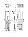
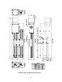
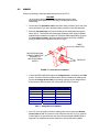
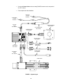
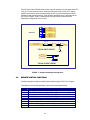
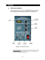
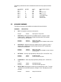
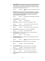
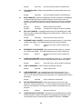
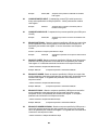
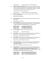
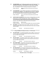
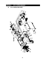
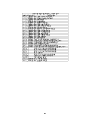
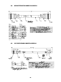
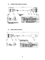
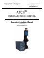
Computer Weld Technology, Inc. 10702 Old Bammel N Houston Rd. Houston, TX 77086 Phone: (713) 462-2118 Fax: (713) 462-2503 Email: [email protected] TM ATC II AUTOMATIC TORCH CONTROL Operation / Installation Manual P/N: S8M5018 Revised: September 4, 2009 Table of Contents 1.0 OVERVIEW..................................................................................................................... 1 2.0 INSTALLATION.............................................................................................................. 3 2.1 2.2 2.3 2.4 3.0 3.1 4.0 4.1 4.2 4.3 5.0 5.1 5.2 5.3 5.5 5.6 ATC CONTROL ........................................................................................................... 3 ATC SLIDE ASSEMBLIES .......................................................................................... 4 CABLES....................................................................................................................... 7 REMOTE CONTROL FUNCTIONS ............................................................................ 9 OPERATION................................................................................................................. 10 OPERATIONAL SEQUENCES................................................................................. 10 ATC II OFF-LINE SERIAL TERMINAL PORT PROTOCOL...................................... 13 SERIAL TERMINAL PORT INTERFACE.................................................................. 13 PORT PROTOCOL.................................................................................................... 13 TERMINAL COMMANDS.......................................................................................... 13 ATC II PROGRAMMABLE SEQUENCE PROTOCOL .............................................. 16 PROGRAMMABLE SEQUENCES ........................................................................... 16 SPECIFIC COMMAND FUNCTION .......................................................................... 16 RELAY OUTPUTS..................................................................................................... 16 AVAILABLE COMMAND ........................................................................................... 17 FACTORY DEFAULTS.............................................................................................. 24 APPENDIX A ATC II SYSTEM DRAWINGS ..................................................................... 26 A.1 A.2 A.3 A.4 A.5 A.6 A.7 ATC II CONTROL ENCLOSURE .............................................................................. 26 MICROSTEP MOTOR CABLE P/N: S3W5034......................................................... 28 VOLTAGE SENSOR CABLE P/N: S3W5044 ........................................................... 28 CURRENT SENSOR CABLE P/N: S3W5045........................................................... 29 POWER CABLE P/N: S3W5043 ............................................................................... 29 TERM CABLE P/N: S3W5050 ................................................................................... 30 REMOTE I/O CABLE P/N: E3W5045 ........................................................................ 30 1.0 OVERVIEW The Computer Weld Technology Automatic Torch Control (ATC II) is a compact, lightweight, weld torch manipulation control system comprised of the micro-controller based Automatic Torch Control (ATC II) and a stepper motor driven Linear Slide Assembly (LSA). This system is capable of providing independent control of all torch movements in the vertical plane. The ATC II provides automatic torch Height control using Computer Weld Technology's patented ThruArc sensing technology. The Thru-Arc sensor provides two modes of Torch Height Control. Mode 4 provides Torch Height Control using Arc Voltage Control (AVC). Mode 5 provides torch height control using Arc Current Control (ACC). The entire Torch tracking information is derived from the welding arc. The arc voltage and welding current is measured with an external voltage probe and Hall-Effect clamp on current sensor provided with the system. The ATC II provides a user definable 50 sequence Programmable Logic Controller (PLC) with four 24vdc inputs and two N.O. relay contacts. Using the PLC the user can provide external program control and simple power source interface. A RS-232 serial port is provided for off-line programming and system configuration. The RS-232 port can also be used to remote control the ATC II. The Automatic Torch Control (ATC II) provides the necessary command signals to the stepper motor powered drive to permit the selection of the following functions from the front panel of the ATC Control box. CONTROL RUN TRACK JOG SPEED GAIN FUNCTION Enable Slide Home and AVC/ACC operation Enable/Disable Thru-Arc AVC/ACC tracking Jog the Torch slide position p or down Control the speed of the slide Provide sensitivity control for all tracking functions The Linear Slide Assembly (LSA) is a stepper motor driven mechanical assembly that provides the motion for weld torch manipulation. The standard LSA provides 7” of vertical motion and has a weight capacity of 25 lbs @ 3” from the face of the carriage. The Torch Slide Assembly module can be installed in any position using the mounting bracket. The mounting bracket can be installed on the bottom or in the center of the back of the slide. ATC II™ ENCLOSURE SPECIFICATIONS Dimensions Weight Power Requirements Velocity Motor Torque 6.62”H X 4.12”W X 8.75”L (168mm X 105mm X 222mm) 5.5 lbs (2.5kg) 115 vac or 42 vac 50/60 Hz @ 220 va 0.2 - 15 inch/min 120 oz-in max (Holding Torque LIGHT DUTY SLIDE SPECIFICATIONS Dimensions Max Travel Weight Velocity Weight Capacity 13.25”H x 4.7”W x 3.5”D (336mm X 102mm x 89mm) 7.25” (184mm) 7 lbs (3.18kg) 0.2 – 1.5 inch/sec 10 lbs @ 3” from slide face 1 MEDIUM DUTY SLIDE SPECIFICATIONS Dimensions Max Travel Weight Velocity Weight Capacity 16.66”H x 3.38”W x 2.88”D (423mm X 86mm x 73mm) 7.25” (184mm) 7 lbs (3.18kg) 0.2 – 1.5 inch/sec 25 lbs @ 3” from slide face HEAVY DUTY SLIDE SPECIFICATIONS Dimensions Max Travel Weight Velocity Weight Capacity 17.08”H x 5.00”W x 2.63”D (434mm X 127mm x 67mm) 7.25” (184mm) 9-1/2 lbs (4.32kg) 0.2 – 1.5 inch/sec 45 lbs @ 3” from slide face 2 2.0 INSTALLATION 2.1 ATC CONTROL The ATC Control assembly should be located to allow easy operator access to the front panel. The control is provided with four 10-32 captive PEM nuts located on the left side of the enclosure. Figure 1 shows the physical mounting dimensions. FIGURE 1 - Control Physical Dimensions 3 2.2 ATC SLIDE ASSEMBLIES See Figure 2, 3 and 4 for mounting locations and physical dimensions for light, medium and heavy duty slides. FIGURE 2- Light Duty Slide Physical Dimensions 4 FIGURE 3- Medium Duty Slide Physical Dimensions 5 FIGURE 4- Heavy Duty Slide Physical Dimensions 6 2.3 CABLES Perform the following to install the cables and sensors for the ATC II. WARNING Do not connect or disconnect the SLIDE MOTOR CABLE from the Slide or ATC II back panel with Power Applied to the control. Doing so will damage the control and slide assembly. Connect the ATC Slide Motor Cable to the Motor mating connector on the rear of the control enclosure (Fig 5) and to the Motor mating connector on the Slide Assembly. Mount the Current Sensor such that the welding ground cable passes through the sensor (Fig 5). The two RED dots should point toward the power supply for GMAW applications and toward the work piece for GTAW and Plasma applications. Connect the Current Sensor Cable to the Sensor Cable Connector and to the CURRENT mating connector on the rear panel of the ATC II (Fig 5). CABLE CONNECTOR NEGATIVE WELDING CABLE TO NEGATIVE TERMINAL OF WELDING POWER SUPPLY RED DOTS FIGURE 5 - Current Sensor Installation Connect the RED and BLACK leads of the Voltage Sensor in accordance with Table 1 below. Connect the lead for the Electrode as close as possible to the welding torch. Connect the Voltage Sensor Cable to the mating connector on the Voltage Sensor and connect the other end to the ATC II rear panel VOLTAGE Connector. APPLICATION GMAW P-GMAW GTAW P-GTAW PAW P-PAW RED (+) LEAD Electrode Electrode Work Work Work Work BLACK (-) Lead Work Work Electrode Electrode Electrode Electrode Table 1 - Voltage Sensor Installation If the ATC II is to be used to control the welding power source connect the Remote Control Cable to DB9 I/O connector on the rear panel of the ATC II (Fig 6). (Remote Control Cable is not part of the base unit and must be purchased separate) Refer to Appendix D for samples interconnect drawings for various weld power supplies. 7 Connect the Power Cable to the rear mating POWER connector on the rear panel of the ATC II (Fig 6). This completes the cable installation. RED WIRE 1/2” RING TERMINAL BLACK WIRE 1/2” RING TERMINAL VOLTAGE CABLE P/N: S3W5044 CURRENT SENSOR P/N: X3Q5010 VOLTAGE SENSOR P/N: S3A5053 CURRENT CABLE P/N: S3W5045 VOLTAGE CABLE P/N: E3W5045 TERM CABLE P/N: S3W5050 ATC II ENCLOSURE P/N: S3A5127 POWER CABLE P/N: S3W5043 MIRCOSTEP CABLE P/N: S3W5034 LINEAR SLIDE FIGURE 6 – System Layout 8 The ATC Control has a DB-9S remote control connector located on the rear panel of the ATC II (Fig 6). The remote inputs can be used to provide remote control of the ATC II and the outputs can be used to control a device through the ATC II (such as Power Source Weld Contactor to start the weld process). These functions are based on the configuration of the ATC II PLC Program. Figure 7 shows the pin-out for the remote connector and the Input/Output configuration for the I/O port. 1 6 2 7 3 8 4 9 5 REMOTE I/O INPUT 1 CR1 N.O. INPUT 2 CR1 COM INPUT COM CR2 N.O. INPUT 3 CR2 COM INPUT 4 R1 4.7K 1/2W (10 - 28) VDC INPUT INPUT COM 1 2 A C C E 16 15 LOGIC +5 INP1 R2 4.7K TYPICAL INPUT CIRCUIT LOGIC COM CR1 N.O. 5 CR1 COM 8 + 1 16 RELAY DC24V TYPICAL OUTPUT CIRCUIT FIGURE 7 - Remote Input/Output Configuration 2.4 REMOTE CONTROL FUNCTIONS All input and output functions are defined and controlled using he ATC II PLC Program The following is a functional description of the remote control specifications: PIN 1 2 3 4 5 6 7 8 9 FUNCTIONS INP1 - 24 vdc remote input 1 (24vdc @ 5.0 ma. Active High) INP2 - 24 vdc remote input 1 (24vdc @ 5.0 ma. Active High) INP COM - Digital input signal common INP3 - 24 vdc remote input 1 (24vdc @ 5.0 ma. Active High) INP4 - 24 vdc remote input 1 (24vdc @ 5.0 ma. Active High) CR1-A - CR1 relay Normally Open (N.O.) output (Default weld contactor) CR1-B - CR1 common output (Default Weld contactor) CR2-A - CR2 relay Normally Open (N.O.) output (Default arc active) CR2-B - CR2 common output (Default arc active) 9 3.0 OPERATION 3.1 OPERATIONAL SEQUENCES The following operational sequence is based on the DEFAULT PLC program provided with the unit. The operation may vary based on user defined PLC code. Refer to Section 5 for PLC programming information. Figure 8 shows the location of the operator controls. AVC SETTING CONTROL AVC DISPLAY SPEED CONTROL GAIN CONTROL RUN SWITCH TRACKING SWITCH SLIDE JOG SWITCH POWER SWITCH FIGURE 8 - Front Control Panel Layout To operate the control, turn the main power switch to the "Up" position. The power switch will illuminate indicating that the unit is operational. The AVC Display will illuminate and display the active AVC setting. 10 To initialize the slide, turn the "RUN" switch to the "On" position. The Torch slide will move to the upper slide limit switch and stop. Turn the “RUN” switch to the “Off” position. This operation must be performed every time the ATC II is powered on. The front panel controls will remain inoperable until the slide is initialized. To change the Slide speed, adjust the "SPEED" control. To change the AVC set point value adjust the "AVC" control. To move the Torch Slide use the "JOG" switch. Holding the "JOG" switch in the "UP" direction will move Torch Slide in the up direction. Holding the "JOG" switch in the "DOWN" position will move the torch slide in the down direction. The "JOG" switch is disabled when the "TRACKING" Switch is on and the "ARC IS ACTIVE". How to Set and Save the Torch Start Weld Position. 1. With the "RUN" switch in the "OFF" position use the "JOG" Switch to move the Torch to the desired START WELD position. 2. To Save the START WELD position set the “RUN” switch to the “ON” position. By performing this operation the ATC will store the START WELD position of the torch slide. After the START WELD position is saved it can be restored to the saved START WELD position by toggling the “RUN” switch to the “Off” position. After the START WELD position has been restored move the "RUN" switch back to the "ON" position. To operate the ATC II without saving a START WELD position place the “RUN” switch in the “ON” position. Using the “JOG” switch set the torch to the desired weld start position. To enable the AVC tracking set the “TRACKING” switch to the “ON” position. Start the welding arc and the AVC control will begin operation when the arc is detected. To adjust the AVC set point, adjust the “AVC” control to the desired level. To halt the AVC torch tracking toggle the “TRACKING” switch to the “OFF” position. When the Tracking switch is “OFF” the “JOG” switch will be enabled and the operator can manually adjust the torch position. To start a welding sequence using the DEFAULT PLC PROGRAM: Turn the "RUN" switch to the "ON" position. The ATC II will activate the CR1 output relay (connected to the Power Source Contactor through the optional Remote I/O Cable) and will wait for an arc on condition. An arc on condition is set when the current is greater than 8 amps and the voltage is greater than 3.0 volts as detected by the Voltage and Current Sensor of the ATC II. The arc active signal will be reset if current or voltage falls below preset values and tracking will stop. When the arc is active CR2 will be set. 11 To activate the selected tracking mode set the "TRACKING" switch to the "ON" position. To disable the selected tracking mode set the "TRACKING" switch to the "OFF" position. While tracking the "GAIN" control can be used to adjust the sensitivity of the tracking. If the Torch is moving UP and DOWN too much the GAIN may be too HIGH. If the Torch moves too little the GAIN is too LOW. Adjust the GAIN until the Torch movement is stable. NOTE: If excessive "GAIN" is used the torch slide will over-correct and the weld bead will wander. Decrease the gain to obtain stable torch tracking. The control will start the tracking from the last position as determined when the "RUN" switch is set to the "ON" position. When the "TRACKING" switch is set to the "OFF" position the AVC control will be disabled. When the "TRACKING" switch is in the "OFF" position the Torch position can be moved by activating the "JOG" switch in the "UP" or "DOWN" position. When the "JOG" is returned to the center position the control will use the new torch position as the new start location. 12 4.0 ATC II OFF-LINE SERIAL TERMINAL PORT PROTOCOL 4.1 SERIAL TERMINAL PORT INTERFACE The RS-232 communications port is used to off-line program the ATC II PLC sequences drive motor parameters and the operating parameters for the ATC II. The Protocol is a simple ASCII command string that allows the user to up-load or download the various parameters. The serial port is configured for the following data format: Baud Rate: Word Length: Hand Shaking: 4.2 9600, Full Duplex 8 Data Bits, One Stop and no parity None PORT PROTOCOL The Protocol consists of a command string and optional data bytes. The command string is an Alpha character and option number followed by a "=" or "?" followed by optional data and terminated with an ASCII "cr" (0dh). The "=“ will indicate that data is being sent to the select parameter by the host controller. The "?" will indicate a request for data from the ATC II to the Host controller. If the host is up-loading data to the ATC II the data will be placed after the "=" character and will be an ASCII string terminated with an ASCII "cr" (0dh). The following is an example of sending a new step motor speed to the ATC II: V1=1000(cr) - Sent from Host To read the ATC II step motor speed, send the following command: V1?(cr) 1000(cr) 4.3 - Sent from Host - Received from ATC II TERMINAL COMMANDS The following is a summary of the RS-232 serial Commands supported by the ATC II: COMMAND DESCRIPTION A1 - A4 Read ATC II Analog Inputs. The following is a summary of the analog command functions: A1 - AVC Control Pot input (1 to 255 = 0.01 to 25.5 on the display). A2 - Speed Pot input (255 = 5.12 vdc Step Rate = Value * Rate Multiplier (M5)). A3 - Not Used. A4 - Not Used. A5 - Not Used. A6 - Gain Pot analog input (255 = 5.12 vdc). A7 - Current sensor excitation current (255 = 255 ma.) A8 - Set motor Excitation current reference (255 = 2.55 amps). 13 M0 - M5 Set system control mode functions: M0 - Set programmable sequence number to value. M1 - Read Switch input status (1 = on, 0 = off) BIT 0 = Remote INP1 (value= 1). BIT 1 = Remote INP2 (value= 2). BIT 2 = Slide Home Limit (value= 4). BIT 3 = Remote INP4 (value= 8). BIT 4 = "JOG UP" switch input (value= 16). BIT 5 = "JOG DOWN" switch input (value= 32). BIT 6 = "RUN" switch input (value= 64). BIT 7 = “Track” switch input (value= 128). M2 - Set output relays CR1 - CR2 (1=on, 0=off). BIT 0 = Relay CR1 (value= 1) BIT 1 = Relay CR2 (value= 2) M3 - Set Step motor current value #.## amps (.55 - 2.55 amps). M4 - Set Current sensor excitation value (1 - 255). M5 - Set motor step rate multiplier value. Motor speed = [1 / (Value x Rate)]. M6 - Step motor scale factor (Steps / Distance). M7 - Analog input automatic scan starting parameter (0 - 5). When the value is set to zero the front panel pot values will be used. To disable the pot controls set the scan value to 6. This will enable off-line programming of the oscillator parameters. M8 - CWT LAN ID number. Setting a LAN ID value will disable the RS-232 communications and enable the LAN communications routines (Range 1 - 4). M9 - Enable ATC II auto sequence routines. Command M9=1 M9=2 M9=3 M9=4 Function Enable Auto sequence input Clear Auto sequence input Set Initialize sequence input Calculate maximum position based on external limit switch inputs. M10- Tracking gain. M11- Set the Auto Arc On detection current level (0 – 255 amps). M12- Enable/Disable tracking data up-load (1 = Enable, 0 = Disable). M13- Set Tracking mode: 0 = Center line Tracking. 1 = Width control tracking. 2 = Left side Tracking with constant width 3 = Right side tracking with constant width. ********* Firmware Version 1.22 or higher ********* 4 = AVC torch height control (Ver 1.22 or greater) 5 = ACC Torch Height control (Ver 1.22 or greater) M14- Depth of penetration value used for tracking modes 1 - 2. The value controls the depth of penetration of the arc into the sidewall of the welding bevel. M15 Torch height correction sample time period (10 – 255 msec) S1 - S50 Programmable Sequence Commands - See Section 5.0 for description of programmable sequence commands and data format. 14 V1 - V9 Write/Read double byte variables: V1 = Motor speed value. V2 = Current Drive Position (Scaled step motor count). V3 = Move position value. Decrement by the step motor drive command. V4 = Maximum oscillator position limit. V5 = Slide center position. V6 = Slide Oscillator width. V7 = Maximum Slide Oscillation width limit used by the adaptive width tracking mode 1. V8 = Minimum Slide Oscillation width limit used by the adaptive width tracking mode 1. V9 = Current torch to work position. V10= Maximum cross seam correction limit. V11= Maximum torch to work correction limit. ***************** Firmware Version 1.22 or higher ******************************* V12= Torch to work reference voltage used in tracking mode 4 and 5 V13= Torch to work reference current used in tracking mode 4 and 5 V14= Actual Arc Voltage value (0.1 volt increments, 100 = 10.0 volts) V15= Actual Arc Current value (1 amp increment, 100 = 100 amps) In addition to the terminal commands the ATC II supports several special control key functions. These functions are used to save the programmed data in the EEPROM and to clear any pending terminal commands. The following commands are generated by pressing the CTRL" and specified letter key at the same time. When sending any of the following control codes, the ATC II will respond with an ASCII "CR". The following is a summary of the special control character function supported by the ATC II: Control Code Command Function ^W Save current parameters and sequence values to ATC II EEPROM ^C Reset the terminal serial port and clear any pending terminal commands ^S Up-load stored sequence commands from ATC II to terminal. ^R Load sequence commands from EEPROM to RAM 15 5.0 ATC II PROGRAMMABLE SEQUENCE PROTOCOL 5.1 PROGRAMMABLE SEQUENCES The ATC II programmable sequence consists of a 3-byte command. The First byte is the command byte followed by a two-byte value: {Byte1}, {Byte2 (MSB)(:)Byte3 (LSB)} The value bytes must be set even if not required by the command. The value bytes may be branch addresses or real data passed to the selected function. The Command and value must be separated by a comma. The MSB byte and LSB byte of the value may be separated by a colon (":"). The colon will cause the MSB and LSB byte to concatenate to form a single twobyte value. 5.2 SPECIFIC COMMAND FUNCTION When setting MSB and LSB bytes for specific command function the MSB and LSB byte may be separated by a ":" or the total value may be specified by the decimal equivalent of the two bytes. To set the decimal value for the MSB and LSB bytes use the following equation: Decimal Value = (MSB x 256) + LSB The following is an example of how to set sequence 4 to the "SWITCH ON" command (1) and branch to sequence number 10 when "OFF" (MSB) and to test switch input 1 (LSB): Decimal Value = (MSB x 256)+LSB = (10 x 256)+1 = 2561 Decimal Command sent to ATC II:S4=1,2561 Optional Command format: S4=1,10:1 5.3 RELAY OUTPUTS When Setting / Resetting the relay outputs the individual relays are selected by setting the decimal value for each relay and use the result as the value for the command. The following is an example of programming sequence 5 to set relay CR1 and CR2 using the "SET RELAY" command (2): Decimal Value for CR1 = 1 and CR6 = 3 Decimal Value = 1 + 2 = 3 Command sent ATC II: S5=2,3 16 The following is the decimal value for individual bits used for the relay outputs and switch inputs: BIT NUMBER BIT 0 BIT 1 BIT 2 BIT 3 BIT 4 BIT 5 BIT 6 BIT 7 5.5 DECIMAL 1 2 4 8 16 32 64 128 RELAY CR1 CR2 N/A N/A N/A N/A N/A N/A SWITCH INPUT SWITCH INP1 INP2 Slide Home Limit INP4 "JOG UP" Switch "JOG DOWN" Switch "RUN" Switch “TRACK” Switch AVAILABLE COMMAND The following is summary of the available commands and the required values: COMMAND 0 DESCRIPTION NOP - No Operation increment to next sequence Example: 1 S20=2,0:1 S20=2,40:1 ;Wait for input 1 "OFF". ;If input 1 is "ON" branch to SEQ40. If "OFF" increment to next sequence S20=3,2 S20=3,3 ;Set CR2 relay output. ;Set CR1 and CR2 relay output CLEAR RELAY - Clear relay output specified by LSB byte (CR1 = 64 and CR2 = 128). Example 1: Example 2: 5 ;Wait for input 1 "ON". ;If input 1 is "OFF" branch to SEQ40. If "ON" increment to next sequence SET RELAY - Set relay output specified by LSB byte (CR1 = 64 and CR2 = 128). Example 1: Example 2: 4 S20=1,0:1 S20=1,40:1 SWITCH OFF - LSB selects switch input, MSB is branch to sequence number if switch is "ON". If MSB is zero, function will wait for switch "OFF" condition then increment to next sequence. Example 1: Example 2: 3 ;Skip sequence - No operation. SWITCH ON - LSB selects switch input MSB is branch to sequence number if switch is "OFF". If MSB is zero, function will wait for switch "ON" condition then increment to next sequence. Example 1: Example 2: 2 S20=0,0 S20=4,2 S20=4,3 ;Reset CR2 relay output. ;Reset CR1 and CR2 relay output DELAY TIME - Delay program execution by time specified by the value. The value specified is in 10 msecond increments. (Example: 13,50 Set delay time to 0.50 seconds) Example: S20=5,20 ;Delay for 0,20 seconds. 17 6 AUTO EXECUTE - If the Auto execute input is active branch to LSB sequence. If the Auto Execute input is not active branch to sequence number specified by the MSB. If MSB is 0 the function will wait until the input becomes active. If input is active the function will branch to the sequence number specified by the LSB byte. If the LSB is 0 the function increment to the next sequence. Example: 7 S20=11,1000 ;Set current position to 1000. S20=12,0 ;Save current position. S20=13,0 ;Restore save position and move oscillator to the saved position. S20=14,1000 ;Move oscillator to position specified. S20=15,10000 ;Set oscillator maximum to position 10000. LOAD POSITION TO MAX - Set maximum position limit to current position. Example: 17 ;Set motor speed to low speed ( [1 / (Value * Rate)] ). SET MAXIMUM POSITION - Set maximum position limit to value specified. Example: 16 S20=10,20 MOVE TO POSITION - Move to position and increment to next sequence. Example: 15 ;Halt current move command and stop motor drive. RESTORE POSITION - Move to position saved in temporary position register and increment to next sequence. Example: 14 S20=9,0 SAVE POSITION - Save current position encoder count to temporary position register and increment to next sequence. Example: 13 ;Clear Initialize Flag. SET POSITION - Set current position to value specified by [MSB:LSB]. Example: 12 S20=8,0 SET SPEED - Value equal new drive velocity [LSB] (1 - 255). Example: 11 ;If the initialize flag is set jump to SEQ 20 else jump to SEQ 10. HALT MOVE - Halt current move command and stop stepper drive motor. Example: 10 S20=7,10:20 CLEAR INITIALIZE - Clear initialize input. Example: 9 ;If the auto active flag is set jump to SEQ 20 else jump to SEQ 10. INITIALIZE - If the Initialize input is active branch to LSB sequence. If the Initialize input is not active branch to sequence number specified by the MSB. If MSB is 0 the function will wait until the input becomes active. If input is active the function will branch to the sequence number specified by the LSB byte. If the LSB is 0 the function increment to the next sequence. Example: 8 S20=6,10:20 S20=16,0 ;Load current oscillator position to Max position. JOG POSITION CW - Add value specified to current position and move to new position. 18 Example: 18 ;Increment Loop counter 1 and set condition code register. S20=22,1 ;Decrement Loop counter 1 and set condition code register. S20=23,1 ;Clear Loop counter 1 and set condition code register. S20=24,40 ;Jump to sequence S40. S20=25,40 ;Jump to subroutine at sequence S40. RETURN FROM SUBROUTINE - Returns the sequence counter to the "jump subroutine " sequence number plus 1. If a return subroutine command is executed with out a "jump subroutine " the sequence counter will be incremented to the next sequence. Example: 27 S20=21,1 JUMP SUBROUTINE - Jump to specified sequence number subroutine. The sequence subroutine must be terminated with a return from subroutine command (32). The ATC II allows nesting of up to 5 subroutines. All commands may be used in subroutines. Example: 26 ;Load Loop counter 1 with a value of 25. JUMP TO SEQUENCE - Jump to sequence specified by LSB byte. Example: 25 S20=20,25:1 CLEAR LOOP COUNTER - Clears the selected loop counter (0 - 4). The LSB byte selects the desired loop counter to be cleared and sets the condition code register. Example: 24 ;Wait for oscillator move complete ;Is oscillator move complete? No - Branch to SEQ 40 DECREMENT LOOP COUNTER - Decrement the selected counter (0 - 4) and set the condition code register. The LSB byte selects the loop counter to decrement. Example: 23 S20=19,0 S20=19,40:0 INCREMENT LOOP COUNTER - Increment the selected counter (0 - 4) and set the condition code register. The LSB byte selects the loop counter to Increment. Example: 22 ;Jog current position 100 steps in the CCW direction. SET LOOP COUNTER - Load selected loop counter (0-4) with starting value. MSB byte is the value to load and the LSB byte is the selected counter. There are 5 Loop counters available. Example: 21 S20=18,100 MOVE COMPLETE - Has drive completed the last move command? If the MSB byte is set the function will jump to the selected sequence number if the move is not complete. If the LSB byte is zero the function will wait for the move to be completed then increment to the next sequence or branch to the sequence number set by the LSB. Example 1: Example 2: 20 ;Jog current position 100 steps in the CW direction. JOG POSITION CCW - Subtract value specified from current position and move to new position. Example: 19 S20=17,100 S20=26,0 ;Return from subroutine. COMPARE VALUE TO POSITION - Compares the value (MSB, LSB) to the current position and set the condition code register. The comparison is a subtraction of the current position from the command value (CURRENT POSITION - COMMAND 19 Example: 28 S20=28,3 ;Compare input to 3 (Input 1 and 2 active) and set condition code register. COMPARE LOOP VALUE - Compares the loop counter specified by the LSB byte to VALUE). Example: 30 ;Compare current position to 1000 and set condition code register. COMPARE SWITCH INPUT - Compares the current ATC II switch inputs to the binary value specified in the LSB byte (SWITCH - VALUE) and sets the condition code register. Example: 29 S20=27,1000 S20=29,10:1 ;Compare Loop counter 1 to 10 and set condition code registers. BRANCH NOT EQUAL - Branch to sequence specified by LSB byte as a result of the previous parameter value not being equal to command value or not equal zero. As specified by the condition code register. If not zero increment to next sequence number. Function: (Parameter != Compare) then Branch to Seq # Example: 31 S20=30,40 ;If comparison parameter is not equal to value branch to SEQ 40. RANCH IF LOWER - Branch to sequence specified by LSB as a result f the previous parameter value being less than the command value. As specified by the condition code register. If not less than stored value increment to next sequence number. Function: Parameter < Compare then Branch to Seq # Example: S20=31,40 32 ;If comparison parameter < value branch to SEQ 40. BRANCH IF HIGHER - Branch to sequence specified by LSB byte as a result of the previous parameter value being greater than the command value. As specified by the condition code register. If not greater than parameter value increment to next sequence number. Function: Parameter > Compare then Branch to Seq # Example: S20=32,40 33 ;If comparison parameter > value branch to SEQ 40. BRANCH IF EQUAL - Branch to sequence specified by LSB byte as a result of the previous parameter value being equal to the command value (Note: result of comparison is zero). As specified by the condition code register. If not equal to parameter value increment to next sequence number. Function: Parameter = Compare then Branch to Seq # Example: S20=33,40 34 ;If comparison parameter = value branch to SEQ 40. BRANCH IF HIGHER OR EQUAL - Branch to sequence specified by LSB byte as a result of the previous parameter value being greater than or equal to the command value. As specified by the condition code register. If not greater than command value increment to next sequence number. Function: Parameter >= Compare then Branch to Seq # 20 Example: S20=34,40 35 ;If comparison parameter => to value branch to SEQ 40. BRANCH IF LESS THEN OR EQUAL - Branch to sequence specified by LSB byte as a result of the previous parameter value being less than or equal to the command value (Note: result of comparison is zero). As specified by the condition code register. If not equal to parameter value increment to next sequence number. Function: Parameter <= Compare then Branch to Seq # Example: S20=35,40 36 ;If comparison parameter <= to value branch to SEQ 40. START OSCILLATOR - Start the mechanical oscillation based on current width, speed, and dwell parameters. Example: S20=36,0 ;Start oscillation. 37 STOP OSCILLATOR - Halt the current oscillation and move oscillator to the current center position. Example: S20=37,0 ;Stop oscillation. 38 START TRACKING - Start centerline tracking with the mode specified by the [LSB] byte. The following are the valid tracking mode commands: 0 = Centerline tracking, 1 = Width control tracking, 2 = Right side tracking, 3 = Left side tracking. Example 1: S20=38,0 Example 2: S20=38,1 Example 3: S20=38,2 Example 4: S20=38,3 39 STOP TRACKING – Disable the centerline tracking functions. Example: S20=39,1 40 Start tracking using the centerline mode Start tracking using the width mode Start tracking using the Right side mode Start tracking using the Left side mode Disable center line tracking CR1 ON/OFF - Activate CR1 based on the [LSB] specified input. If the [LSB] input is active set CR1,. If the [LSB] byte specified input is inactive reset CR1. Example: S20=38,1 ;Set/Reset CR1 based on input 1 status 41 CR2 ON/OFF - Activate CR2 based on the [LSB] specified input. If the [LSB] input is active set CR2,. If the [LSB] byte specified input is inactive reset CR2. Example: S20=39,1 ;Set/Reset CR2 based on input 1 status 42 OSCILLATOR ON/OFF – Activate the Oscillator based on the [LSC] specified input. If the [LSB] input is active start the Oscillator. If the [LSB] byte specified input is inactive stop the oscillator. Example: S20=40,1 ;Start/Stop the oscillator based on input 1 status 43 TRACK ON/OFF - Activate the tracking mode specified by the [MSB] based on the [LSB] specified input. If the [LSB] input is active, start the tracking mode specified by the [MSB] byte. If the [LSB] byte is inactive disable the tracking function. The following are the valid tracking mode [MSB] values: 0 = Centerline tracking, 1 = Width control tracking, 2 = Right side tracking, 3 = Left side tracking. Example 1: S20=43,0:1 Example 2: S20=43,1:1 Example 3: S20=43,2:1 Example 4: S20=43,3:1 If INP 1 is active start tracking using the centerline mode If INP 2 is active start tracking using the width mode If INP 1 is active start tracking using the Right side mode If INP 2 is active start tracking using the Left side mode 21 44 JOG CW ON/OFF - Jog the oscillator center position in the CW direction by the value specified in the [MSB] byte. The [LSB] specifies the input to test. If the [LSB] specified input is active jog the center position by the value specified in the [MSB] byte. If the [LSB] byte is inactive the change center position is unchanged. Example: S20=41,10:1 45 ;If INP 1 is active increment center position 10 steps in the CW direction JOG CCW ON/OFF - Jog the oscillator center position in the CCW direction by the value specified in the [MSB] byte. The [LSB] specifies the input to test. If the [LSB] specified input is active jog the center position by the value specified in the [MSB] byte. If the [LSB] byte is inactive the change center position is unchanged. Example: S20=42,10:1 46 ;If INP 1 is active increment center position 10 steps in the CCW direction WAIT FOR ARC ON CONDITION - Wait for valid arc condition defined by arc voltage greater then 2.5 volts and current greater then 10 amps. If MSB byte is set the function will branch to the selected sequence number while the ARC ON Flag is clear. If the LSB is set and the "ARC ON" flag is set the function will branch to the specified sequence. If the LSB is zero the function will increment to next sequence. Example 1: S20=46,0 Example 2: S20=46,40:30 47 Wait for Arc Active. If Arc is not active branch to SEQ 40. If Arc is active branch to SEQ 30 SET WIDTH - Set oscillation width control to [LSB] (0 - 255) value. This function is used to set a default width Pot value when the auto scan function is set to 5 to disable user Pot controls. Example: S20=47,20 ;Set oscillation width to LSB value. ************ Only Available In Firmware Version 1.21 Or Greater ************* 48 SET RIGHT DWELL - Set oscillation Right Dwell control to [LSB] (0 - 255) value. This function is used to set a default Right Dwell Pot value when the auto scan function is set to 5 to disable user Pot controls. Example: 49 S20=49,20 ;Set oscillation Left Dwell to LSB value. SET CENTER DWELL - Set oscillation Center Dwell control to [LSB] (0 - 255) value. This function is used to set default Center Dwell Pot value when the auto scan function is set to 5 to disable user Pot controls. Example: 51 ;Set oscillation Right Dwell to LSB value. SET LEFT DWELL - Set oscillation Left Dwell control to [LSB] (0 - 255) value. This function is used to set a default Left Dwell Pot value when the auto scan function is set to 5 to disable user Pot controls. Example: 50 S20=48,20 S20=50,20 ;Set oscillation Center Dwell to LSB value. SET TRACKIN GAIN - Set Cross Seam Tracking Gain control to [LSB] (0 - 255) value. This function is used to set default Tracking Gain Pot value when the auto scan function is set to 5 to disable user Pot controls. Example: S20=51,20 ;Set Tracking Gain to LSB value. ******************************** Firmware 22 Version 1.22 or Higher ********************************* 52 SET VOLT REFERANCE - Set Voltage reference to the value and increment to the next sequence. This value is used as a reference for torch height control tracking mode 4 or 5. The units are in 0.1-volt increments (i.e. 100 = 10.0 volts) Example: 53 S20=55,1 ;Home vertical slide using INP1 as home limit. S20=56,1 ;Set Volt Reference to the Width Pot. S20=56,3 ;Set Current Reference to the Center Dwell Pot. MOVE SLIDE CW BY INPUT VALUE – Move slide in CW direction based on Input Value specified by the [LSB] at the speed specified by the [MSB]. This function moves the slide in the CW Direction when the Input Value is equal to the Value in the [LSB] at the speed indicated in the [MSB]. Example: 59 ; 100 step retract and 2 step down increment . SET CURRENT REF TO POT - Set Current reference, for torch height tracking, to the Pot value specified by the [LSB]. This function is used to set torch tracking reference current to the value controlled by the selected control panel pot. The auto scan function must be enabled. The [LSB] sets the control panel pot that is used (0 = A1… 5 =A6). Example: 58 S20=54,100:2 SET VOLT REF TO POT - Set Volt reference, for torch height tracking, to the Pot value specified by the [LSB]. This function is used to set torch Tracking reference voltage to the value controlled by the selected control panel pot. The auto scan function must be enabled. The [LSB] sets the control pot that is used (0 = A1… 5 =A6). Example: 57 ;Set Torch height to 220 amps. HOME SLIDE – Find Upper home position of a vertical slide assemble. Requires external N.C. upper limit switch to indicate home position. The [LSB] byte specifies the remote input used to indicate the Home position. This command will set the current slide position to the user defined V4 max position limit and will move the slide up until the selected remote input [LSB] is inactive or the max position step count has been reached. Example: 56 S20=53,220 TOUCH-RETRACT – This command provides an automatic touch retract torch routine. The [MSB} byte sets the retract distance and the [LSB] sets the step down increments. When this command is executed the Torch slide will be move down until the sensed arc voltage falls below 0.8 volts. The command will then halt the down ward motion and back up the number of steps set in the [MSB] byte. This routine requires an external voltage source be applied to the torch and is normally used with GTAW application. Example: 55 ;Set Torch tracking voltage to 23.0 volts. SET CURRENT REFERANCE - Set Current reference to the value and increment to the next sequence. This value is used as a reference for torch height control tracking mode 4 or 5. The units are in 1-amp increments (i.e. 100 = 100 amps). Example: 54 S20=52,230 S20=58,200:16 ;If Input Value Equals 16 (Input 5 is Active) Move Slide Down at Speed of 200. MOVE SLIDE CCW BY INPUT VALUE – Move slide in CCW direction based on Input value specified by the [LSB] at the speed specified by the [MSB]. This function 23 Example: 5.6 S20=58,200:16 ;If Input Value Equals 16 (Input 5 is Active) Move Slide UP at Speed of 200. FACTORY DEFAULTS As shipped from the factory the ATC II has a basic operation PLC program. The PLC code allows the user to start/stop the welding process using the "RUN" switch. By connecting the CR1 relay output to the "Gun Switch" input on the wire feeder the ATC II will activate the welding system. When an arc is established the oscillator will be activated. The centerlinetracking mode will be activated when the operator activates the "TRACKING" switch. The PLC code is divided into three sections. The first section is the non-welding routine and consists of Sequence 1 - 5. This section checks the various input control switches and will jog the oscillator center, start/stop the oscillator and start the welding sequence. The second section is the welding routines. When the "RUN" switch is active the CR1 relay is set and the PLC code will wait for an arc on condition. When the arc is established the oscillator will automatically start. When the "TRACKING" switch is activated the ATC II will begin centerline tracking. To change the mode of tracking the user will need to change line S10 to reflect the desired tracking mode. The operator can also jog the oscillation center position using the "JOG" control switch. The following is a listing of the default PLC program provided: ;======== ATC II AVC TRACKING SYSTEM CONFIGURATION PARAMTERS ======== ; CR1 - Cycle Start Latch Relay Output ; CR2 - ARC Active Travel Start Relay ; INP1 - Not Used ; INP2 - Not Used ; INP3 - Slide Home Input ; INP4 – Not Used ; ;=========================== ATC II Default PLC =========================== S1=25,30 ; Jump to Initialize Subroutine S30 ;=============== Idle Switch Test Routine===================================S2=25,25 ; Jump to Jog Up/Down Subroutine S25 S3=1,2:64 ; IS RUN SWITCH ON - NO GO TO SEQ 2 ;================== WELD "ON" ROUTINE ================================= S4=12,0 ; Save Current Position S5=3,1 ; SET RELAY 1 "CYCLE ON" S6=1,16:64 ; Is RUN Switch still active? No End Weld S7=25,25 ; Check JOG switch inputs S8=46,6:9 ; IS ARC ACTIVE? NO - GO TO S8 AND RECHECK ;------------------- ARC Active Scan Routine -------------------------S9=3,2 ; SET ARC ACTIVE RELAY CR2 S10=43,4:128 ; START/STOP CENTER LINE TRACKING BASED ON SWITCH? S11=2,13:128 ; IF Tracking on THEN skip Jog Switch Test S12=25,25 ; ELSE - Check for Jog Switch Command S13=56,0 ; Load A1"Volt" pot to Volt Reference S14=1,16:64 ; IS WELD SWITCH STILL ON - NO GOTO S16 END WELD S15=46,16:9 ; IS ARC STILL ACTIVE - NO GOTO S22 ELSE GOTO S16 ;=================== END WELD CYCLE ================================== S16=39,4 ; STOP CENTER LINE TRACKING S17=4,2 ; RESET CR2 "ARC ACTIVE" RELAYS S18=2,6:64 ; Wait for Input Off S19=3,1 ; Reset "Cycle On" Relay S20=10,255 ; Set Speed S21=13,0 ; Restore Position S22=19,0 ; Wait for Move Complete S23=24,2 ; JUMP TO SEQ 2 24 ;=============== Jog Up/Down Subroutine =================================== S25=58,200:32 ; IF CW SWITCH ON - JOG CW S26=5,5 ; Delay S27=59,200:16 ; IF CCW SWITCH ON - JOG CCW S28=26,0 ; Return from Subroutine ;=============== Initialize Routine =========================================S30=1,64 ; Wait for "RUN" switch on S31=4,3 ; Reset all Relays S32=5,1 ; Delay S33=55,4 ; Home Slide and wait for Input 3 S34=19,0 ; Wait for Move Complete S35=11,1 ; Reset position Register S36=2,64 ; Wait for Run Switch Off S37=26,0 ; Return from Subroutine 25 APPENDIX A A.1 ATC II SYSTEM DRAWINGS ATC II CONTROL ENCLOSURE 26 27 A.2 MICROSTEP MOTOR CABLE P/N: S3W5034 A.3 VOLTAGE SENSOR CABLE P/N: S3W5044 28 A.4 CURRENT SENSOR CABLE P/N: S3W5045 A.5 POWER CABLE P/N: S3W5043 29 A.6 TERM CABLE P/N: S3W5050 A.7 REMOTE I/O CABLE P/N: E3W5045 30