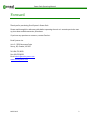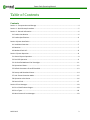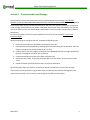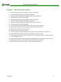
1
M-PP-0113
Power Pack Operating Manual
Unit 2 - 5550 Panorama Drive Surrey, BC Canada V3S 1B7
Tel: 604-576-8333 Fax: 604-576-8233
www.ensolsystems.com
Power Pack Operating Manual
Forward
Thank you for purchasing Ensol System’s Power Pack.
Please read through this reference guide before operating the unit as it contains particular start
up, shut down and disconnection procedures.
If you have any questions or concerns, contact Ensol at:
Ensol Systems Inc.
Unit 2 – 5550 Panorama Drive
Surrey, BC, Canada, V3S 1B7
Tel: 604-576-8333
Fax: 604-576-8233
Email: [email protected]
www.ensolsystems.com
M-PP-0113
2
Power Pack Operating Manual
Table of Contents
Contents
Section 1 – Transportation and Storage ................................................................................................... 4
Section 2 – Quick Startup Procedure........................................................................................................ 5
Section 3 – General Information .............................................................................................................. 6
3.1 Product Introduction...................................................................................................................... 6
3.2 Product Specifications.................................................................................................................... 6
Section 4 System Installation ................................................................................................................... 7
4.1 Installation Overview ..................................................................................................................... 7
4.2 Batteries ........................................................................................................................................ 7
4.3 Methanol Fuel Cell ......................................................................................................................... 8
Section 5 System Operation..................................................................................................................... 8
5.1 General System Operation ............................................................................................................. 8
5.2 Fuel Cell Operation ........................................................................................................................ 9
5.3 UN Certified Methanol Fuel Cartridges......................................................................................... 11
5.4 Operational States ....................................................................................................................... 12
5.5 Default Parameters of cutoff threshold ........................................................................................ 13
5.6 Startup and Shutdown Phases...................................................................................................... 14
5.7 Anti–Freeze Protection Mode ...................................................................................................... 15
5.8 Operation at the Device ............................................................................................................... 16
5.9 Service Fluid................................................................................................................................. 17
Section 6 Error Messages....................................................................................................................... 18
6.1 Error Classifications Ranges.......................................................................................................... 18
6.2 Error Types .................................................................................................................................. 18
6.3 Most Common Error Messages .................................................................................................... 18
M-PP-0113
3
Power Pack Operating Manual
Section 1 – Transportation and Storage
Since the EFOY Pro fuel cells contain water, they must be protected from freezing. IF A FUEL CELL
FREEZES, IT MAY BECOME DAMAGED AND MAY NOT BE COVERED UNDER WARRANTY. When installed in
Ensol’s Power Pack, the fuel cell will keep itself warm, but only if this system is turned on, connected to
a fuel cartridge and to batteries over 9 VDC. If the Power Pack did not come with batteries, the fuel cell
will not be able to run the Anti-Freeze Mode, and therefore must be stored or transported in a heated
atmosphere.
For more information on the Anti-Freeze capabilities of the fuel cell, see section 4.7 Anti-Freeze
Protection Mode.
Before transporting or storing the fuel cell, complete the following steps:
1. Ensure all fuses and/or circuit breakers are closed or set to ‘On’.
2. Check that the fan is operational by dropping the thermostat setting all the way down. Once the
check is completed, set the thermostat to 30°C or 90°F.
3. Confirm that the fuel line is tightly connected to an adequately filled fuel cartridge. Without fuel
the Anti-Freeze Mode will not be able to function.
4. Connect the exhaust/vent lines to the water collection tank.
5. Set the fuel cell to Auto, by pressing the power button on the remote, until the remote reads
‘Auto’.
6. Closed the Power Pack lid and ensure that it is properly sealed shut.
By following these steps, the EFOY Pro should never freeze, provided there is fuel in the cartridge.
If the system is to be stored for a long period of time, periodically check the fuel cartridge level. We
recommend you check it once a month, even though the fuel will last much longer.
M-PP-0113
4
Power Pack Operating Manual
Section 2 – Quick Startup Procedure
1.
2.
3.
4.
5.
6.
7.
8.
9.
10.
11.
12.
13.
14.
15.
Ensure all fuses and/or circuit breakers are open or set to ‘Off’
Connect the battery leads to the batteries if required.
Plug the remote into the RJ45 port labeled ‘Remote’ on the fuel cell.
Connect fuel line to methanol cartridge.
Ensure all fuses and/or circuit breakers are open or set to ‘Off’
Connect the battery leads to the batteries if required.
Plug the remote into the RJ45 port labeled ‘Remote’ on the fuel cell.
Connect fuel line to methanol cartridge.
Insert the exhaust tube from the fuel cell, to the water collection tank port.
Ensure the 2” exhaust port from the water collection tank is connected.
Plug the power connector into the fuel cell.
Close all fuses and/or circuits breakers.
Turn the system on using the power button on the remote, or the button on the fuel cell.
If the display of the remote control shows “Automatic“ – device is ready
Functionality check: Switch on device manually – check if charging starts (this is only possible if
battery voltage < 13.2 V)
16. Ensure the thermostat is set at an appropriate temperature for cooling the unit (less than 45oC).
17. Remove any tools from the enclosure, store service fluid and user manual.
18. Close the enclosure and ensure that it is properly latched and sealed.
M-PP-0113
5
Power Pack Operating Manual
Section 3 – General Information
3.1 Product Introduction
The Ensol Systems Power Pack can be used to provide reliable power for measurement and control
equipment, air compressors, chemical injection, communications, surveillance and a broad range of
other applications.
Powered by a DMFC (Direct Methanol Fuel Cell), these packages are reliable even in the most remote
and harsh environments.
These systems can be used in conjunction with other power systems. Typically Ensol ties the fuel cell
packages into existing solar systems. The design philosophy then is to use solar energy when you have it,
with a methanol fuel cell as a back-up when you don’t. This will provide you with 100% reliable power
even in the darker months of winter.
3.2 Product Specifications
Max. Energy Output
Nominal Power
Hybrid Power Solutions
Nominal Current
@12 V / 24 V
EFOY Pro
600
EFOY Pro
1600
EFOY Pro
2200
600 Wh/day
1,560 Wh/day
2,160 Wh/day
25 W
65 W
90 W
Cascading multiple EFOY Pro units and integrating them
into hybrid solar or wind packages provide significantly
higher power
2.1 A / 1.05 A
5.4 A / 2.7 A
7.5 A / 3.75 A
Operating Temperature
-40 to +45 °C (Storage Temperature 1 to 45°C)
Methanol Consumption
0.9 L/kWh (0.24 US gal/kWh)
Package Dimensions
(L x W x H)
Enclosure Weight
M-PP-0113
960 x690 x660 mm (37.75x27x26 in )
130 kg (285 lbs)
6
Power Pack Operating Manual
Section 4 System Installation
4.1 Installation Overview
The Fuel Cell Power System’s electrical rating is General Purpose and shall therefore be installed outside
the Hazardous location. Typically the system will be mounted 3 meters away from any source of gas and
0.6 meters off the ground.
The Power Pack also has an exhaust port located on the bottom of the unit. In order for the unit to
operate, this port shall not be blocked and needs at least a 30cm space left open below it.
4.2 Batteries
Sealed Lead-Acid batteries may be provided to store the fuel cell energy. Battery cables provide the link
between the batteries, equipment and charging system. Faulty connections can lead to poor
performance, terminal damage, meltdown or fire.
Batteries Inspection
• Examine the outside appearance of the battery. The tops of the batteries and terminal
connections should be clean, free of dirt and corrosion, and dry.
• If fluid is on the top of a gel or AGM battery this means that the battery is being overcharged
and the performance and life will be reduced
• Check battery cables and connections. Replace any damaged cables with a min. #12 AWG.
Tighten any loose connections.
Changing or Disconnecting Batteries
• Use extreme caution while working on the batteries and ensure appropriate PPE is utilized.
• First isolate the batteries from the electrical system by disconnecting all fuses and/or circuit
breakers.
• Disconnect the leads from the batteries, first beginning with the positive leads, then continue to
disconnect the remaining batteries from one another
• When reconnecting the batteries, please ensure that they are wired appropriately for 12 or
24VDC as your electrical system requires. Wiring the batteries incorrectly can result in an over
voltage condition and damage process equipment wired to the Power Package.
• Once the battery bank is connected, check that the voltage going to the system is within the
range (dependent upon a 12 or 24VDC electrical system). If the wiring is correct and the voltage
is still not within the correct range test each battery individually to see if any are defective or
damaged.
• If the voltage is within the range reconnect all the loads via the fuses and/or circuit breakers.
M-PP-0113
7
Power Pack Operating Manual
4.3 Methanol Fuel Cell
The EFOY Pro Fuel Cell will already be mounted, but all its accessories still may need to be connected.
Connect all accessories in the following order:
•
•
•
First, connect the methanol fuel cartridge. Screw the M28 cartridge adapter to the cartridge if
not already done so. Then connect the fuel line to the cartridge. If there is only one cartridge in
the system, screw the fuel line from the fuel cell to the top of the M28 adapter.
Second, connect the exhaust tubing line to the EFOY Pro fuel cell’s exhaust port. This is a small
tube stub protruding just next to the fuel line. Push the other end of the tube into the water
collection tank. Then connect the 2” exhaust pipe through the bottom of the enclosure.
Third, connect the wiring harness and remote to their respective ports. Ensure that the remote
is plugged into the ‘Remote’ RJ45 port and not the ‘Data’ port.
Section 5 System Operation
5.1 General System Operation
The Power Pack is a simple system consisting of a methanol fuel cell to charge a bank of sealed lead-acid
batteries. This stored electrical power is then used to run measurement and control equipment and
whatever other loads may be involved. A typical hybrid application where the fuel cell is connected in
parallel with a solar system is illustrated in Figure 1.
Figure 1 – Hybrid System
M-PP-0113
8
Power Pack Operating Manual
5.2 Fuel Cell Operation
The EFOY Pro fuel cell uses a catalytic process to directly convert methanol into electricity (see Figure 2).
The byproduct of this reaction is water, small amounts of CO2 and heat. To eliminate freezing, the water
must be collected internally. The collected water should be changed out at the point in time that the
fuel cartridge is replaced.
Figure 2
Since the EFOY Pro fuel cell is a ‘smart’ fuel cell, charging and monitoring to the batteries is handled
automatically (example in Figure 3). With the remote, which is included, the user can view the charging
mode, battery voltage, charging current, system operating hours and firmware version, and can also
change the charging mode. By pressing the power button on the remote, the user can turn the system
off, put it in automatic or turn the system on for one charge cycle.
M-PP-0113
9
Power Pack Operating Manual
Figure 3
Ensol Systems has pre-programmed the fuel cell’s parameters for the installation location. If charging
voltage set points need to be altered, please contact Ensol Systems.
For a full description of the EFOY Pro fuel cell’s operation, please see the manual provided by SFC’s
document 101123_UM_EFOY_Pro_GB_v02.
M-PP-0113
10
Power Pack Operating Manual
5.3 UN Certified Methanol Fuel Cartridges
The EFOY Pro uses special plastic fuel cartridges to facilitate ease of use and transport:
•
•
•
•
•
The methanol fuel cartridges are UN certified containers certified for transport on cargo planes.
The containers are spill resistant and designed to withstand significant impact force.
Ensol Systems will recycle empty plastic cartridges and dispose of any residual methanol if
necessary.
28L cartridges are the largest available size and a cartridge adapter is required to use this
cartridge with the EFOY Pro fuel cell. DO NOT THROW AWAY THE CARTRIDGE ADAPTER!
The fuel cell methanol is ultrapure. Do not puncture the cartridge. To avoid contamination, do
not transfer residual methanol from an old cartridge to a new cartridge. DO NOT USE ANY
OTHER METHANOL SOURCE TO FUEL THE EFOY PRO! Impure/contaminated methanol will
severely degrade the performance and life of the EFOY and will VOID WARRANTY.
M-PP-0113
11
Power Pack Operating Manual
5.4 Operational States
•
Note that a minimal battery voltage of 9.0V or 18.5 V is required for the EFOY Pro to start.
M-PP-0113
12
Power Pack Operating Manual
5.5 Default Parameters of cutoff threshold
New charging strategy (firmware 9.20 since mid of August 2010):
•
•
•
•
•
Switch on voltage: 12.3 V (11.0 - 13.0 V), or 24.6 V (22.0 – 26.0 V)
Switch off voltage: 14.2 V (13.5 - 14.7), or 28.4 V (27.0 – 29.4V)
Switch off current: 2 A / 4 A @ EFOY Pro 2200 (0.5 - 10 A)
Switch off time: 3 hours (0 - 5 hours)
This ensures full battery charging and maximizes battery life
M-PP-0113
13
Power Pack Operating Manual
5.6 Startup and Shutdown Phases
M-PP-0113
14
Power Pack Operating Manual
5.7 Anti–Freeze Protection Mode
•
•
•
•
•
•
•
•
Note that the standard Ensol Systems Power Packs are rated to -40°C operation.
THE ANTI-FREEZE PROTECTION MODE WILL NOT WORK WITHOUT FUEL! Please ensure that the
fuel cell does not run out of methanol in freezing temperatures. If the fuel cell freezes, 24 hours
will be required for the fuel cell to warm back up and be returned to service. Please note that
freezing the fuel cell may cause irreversible damage to the fuel cell. If this is the case, the fuel
cell will need to be sent to Ensol for a service.
The Anti-Freeze Mode will keep the EFOY Pro warm while the temperature is below 5oC (This
will work even when the unit is “OFF”).
Anti-Freeze Mode requires the connection to a faultless, adequately charged battery and fuel
cartridge.
Fuel consumption will be dependent upon external temperature differential. Weather,
insufficient insulation, ambient temperature and operating mode can have an impact on fuel
consumption. An approximate fuel consumption estimation is 5-10L for a 5 month winter
period, in Anti-Freeze Mode only.
The EFOY Pro does not give the produced energy to a fully charged battery in Anti-Freeze Mode.
Rather, the stack “burns” methanol and supplies the peripheries (pumps, etc…) to heat up the
system. The batteries will not be overcharged.
The EFOY Pro can operate in -20 oC temperature. Proper heat management and insulation is
required to ensure reliable operation at -40 oC.
Startup temperature (when the Anti-Freeze Mode has not been activated) is 5 oC.
M-PP-0113
15
Power Pack Operating Manual
5.8 Operation at the Device
Remote Control:
M-PP-0113
16
Power Pack Operating Manual
5.9 Service Fluid
•
•
•
•
If service fluid is low the yellow light will turn on at the EFOY Pro and the message “Please refill
service fluid” will appear at the control panel display.
Normally, there is no need to add service fluid prior to the initial start-up, but if the fuel cell has
been stored for a longer period of time, this may need to be done.
Note that the fuel cell produces its own service fluid during operation. This is critical to the
function of the device. If the EFOY Pro is operated continuously at temperatures above the
acceptable operating range (45 oC), the service fluid will be expelled faster than it can be
regenerated and cause a failure. For this reason, it is critical that the thermostat and fan
provided with the Power Packs are maintained in working order and set at an appropriate
temperature.
Service fluid can be added by removing the exhaust line as pictured below.
M-PP-0113
17
Power Pack Operating Manual
Section 6 Error Messages
6.1 Error Classifications Ranges
•
•
•
•
•
•
•
10
20
30
40
50
70
80
Internal hardware or firmware issue - Contact Ensol Systems.
Fuel - Change the cartridge and reset.
Service Fluid - Add service fluid and reset. Check thermostat and fan function.
Environmental Issue – Temperature too high or too low to maintain function.
Battery - Battery voltage too high or low. Check connections. Check solar charge controller.
Reservoir - Internal fuel problem. Check fuel connections and reset.
System - Internal voltage or system error. Reset.
6.2 Error Types
•
•
•
•
•
•
A = Automatic reset (after error cause is remedied)
M = Manual user intervention required
F = Anti-freeze protection is possible from this error, if the error cause currently no longer exists
P = Permanent error (not resettable)
R = Reset required to restart system
W = Warning
6.3 Most Common Error Messages
•
•
•
•
12, 13, 14 - Failure due to blocking of exhaust or circulation pump defect.
32, 31, 30, 41 - Failure due to high surrounding temperature. Check installation and ensure air
circulation is adequate.
52-54 - Check battery (voltage too low) and/or battery connection problem
72, 76 - Failure in Methanol dosing or internal sensors. Possible issues in Methanol cartridge
because of fuel line.
M-PP-0113
18
Power Pack Operating Manual
text
message
erro
r Nr.
type
of
error
Please
contact
Service!
1
P
System
configuration
incomplete
Firmware update failed
Repair required
10
P
Stack defect
Defect component
Repair required
Defect component
Press RESET
If error should remain,
repair required
13
A
(1x30s
)
R/B
F
P
System delivers
no stack power
Different switching on and
off thresholds in cluster
operation
Adjust switching on and
off threshold (via
Hyperterminal)
14
A
(1x30s
)
R
F
P
Circulation pump
defect
Defect component
Repair required
15
P
System error
Error 10 occurred before,
internal problem
Repair required
17
R
F
P
Illogical state
Defect component
Repair required
error description
Please
check
exhaust
hose
Exhaust hose blocked
11
18
M-PP-0113
possible cause of error
A
(1x30s
)
B
R
F
P
A
(1x30s
)
B
R
F
P
Stack power to
low or voltage trip
open circuit
voltage to low
Lack of additional air
action
Take off exhaust hose
and press "reset", if the
system runs without any
problems, the exhaust
tube is blocked.
If error should remain,
repair required
Please check installation
situation, make sure that
there is enough cooling
air (port diameter should
be 10 cm)
Exhaust tube blocked
Repair required
Defect component
Repair required
Exhaust tube or heat
exchanger is blocked /
frozen
Take off exhaust tube and
press "reset"
If error should remain,
repair required
Failure in open circuit
voltage
Repeat start up 3 times to
reheat the stack
Defect component
Repair required
note
Update
current
firmware
version
Update
current
firmware
version
19
Power Pack Operating Manual
text
message
erro
r Nr.
type
of
error
error description
Please
change fuel
cartridge
20
B
R
F
possible cause of error
Empty or no cartridge
Connect a new fuel
cartridge
Tank connector defect
Check if tank connection
is defiled or cracked
Empty fuel
cartridge
Filled or partly filled
cartridge
22
B
R
F
P
No methanol in
the system (at the
beginning of
operation)
Please refill
Service
Fluid
Fuel cartridge sucks
ambient air / fuel
connector inappropriate
connected
Dosing pump blocked or
defect
Caused by operation at
too high ambient
temperatures; lack of
cooling air
Subsequent damage of
frozen stack
30
31
M-PP-0113
B
R
F
P
B
P
Intermediate
reservoir filling
level:
< 30%
Intermediate
reservoir filling
level:
< 5%
action
Connect new cartridge. If
fuel cartridge is not
completely empty, please
shake it, that the intake
hose is free again
- Back off fuel connector
and remove foreign
material.
- Connect fuel connector
tightly
- Maybe you have to
compress the fuel
cartridge firmly while
connected so a deadlock
has the chance to
declamp
- If not --> repair required
Please refill Service Fluid
and make sure that there
is enough cooling air
Repair required
Defect components
Inner tubes are leaky
Mainly concerns systems
produced before end of
2010
30-60 min after initial startup
--> absence of enough
cooling air
- Make sure that there is
enough incoming air
- Press "reset", so the
system has to do the
start-up again
Leakage or defect
component
Repair required
note
In
isolated
cases the
valve of
the EFOY
M5 and
M10 fuel
cartridge
s may not
work.
Please
contact
the SFC
service.
If you
have to
refill
service
fluid to
many
times you
should
please
check
installatio
n as well
as the air
in- and
outlet
Result of
error 30
20
Power Pack Operating Manual
text
message
type
of
error
error description
32
A
B
F
Intermediate
reservoir filling
level < 55 % and
ambient
conditions cause
negative water
balance
41
A
B
F
Error caused by
ambient
temperature
erro
r Nr.
Interruption
:
Surroundin
gs to warm
Interruption
: Please
defrost
device
slowly
Please
insert filter
40
38
A
B
P
B
Please
check
battery
voltage
50
A
B
Error caused by
ambient
temperature
EFOY Pro 2200 XT
only:
Filter not detected
Battery voltage is
too low
(sense line)
possible cause of error
action
System temperature is too
high
- Bring down ambient
temperature
- possibly fan blocked
- inappropriate inlet air
installation
- incoming air blocked by
fuel cartridge or wall
Ambient temperature over
45 °C
System starts up
automatically, if
temperature is under 38
°C: Lower ambient
temperature
Stack temperature below 3
°C (possibly frozen)
Defrost system at room
temperature
(approximately 24 h),
afterwards install the
system again and start
running
Defect component
Repair required
Filter was removed or not
changed correct
Insert filter or repeat
exchange
Voltage metering not in
order (e.g. sense lines not
or not approximately
connected or cut-outs of
the sense line defect
Battery voltage under 9V
respectively 18.5 V
52
M-PP-0113
A
B
Output voltage
too low
(power line)
Voltage metering not in
order (e.g. power lines not
or not approximately
connected or cut-outs of
the power line defect)
note
Please
check
installatio
n
regarding
off-heat
- Take comparative
measurement with circuit
analyser at EFOY-power
plug (two outer pins) and
battery
- check cut-outs of the
connecting cables
Recharge battery with
battery charger, please
change if battery is defect
- Take comparative
measurement with circuit
analyser at EFOY-power
plug (two outer pins) and
battery
- check cut-outs of the
connecting cables
Battery voltage between
16 V and 18.5V --> no
detection if 12 V or 24 V
application is connected
Recharge battery with
battery charger, please
change if battery is defect
Battery voltage under 9V
respectively 18.5 V
Recharge battery with
battery charger, please
change if battery is defect
21
Power Pack Operating Manual
text
message
erro
r Nr.
type of
error
error description
possible cause of error
Voltage metering of the
battery is not in order
(e.g. sense line not or
not correctly connected
or cut-out of sense line
defect)
51
A
B
Battery voltage
too high
(sense line)
Parallel connected
charge controller hoist
battery voltage too high
or reacts to slowly
Battery voltage over 16
respectively 30.5 V
Output voltage metering
is not in order
53
A
B
Output voltage
too high
(power line)
Parallel connected
charge controller hoist
battery voltage too high
or reacts to slowly
Battery voltage over 16 V
Please
contact
service
M-PP-0113
54
P
Faulty
measurement of
battery voltage
In operation with several
charging sources
action
note
- Take
comparative
measuremen
ts with a
multimeter
at the EFOY
power pins
(two outer
pins) and the
battery
- check cutouts of the
connecting
cables
- Check
external
charge
controller
- Possibly
caused by
alternator
(inside of the
vehicle)
Check
external
charge
controller, if
necessary
disconnect
to avoid
damage
Take
comparative
measuremen
ts with a
multimeter
at the EFOY
power pins
(two outer
pins) and the
battery
- Check
external
charge
controller
- Possibly
caused by
alternator
(inside of the
vehicle)
Check
external
charge
controller, if
necessary
disconnect
to avoid
damage
Update to
firmware
9.16
Solved with firmware
9.16
22
Power Pack Operating Manual
text
message
Please
contact
Service
erro
r Nr.
type of
error
error description
70
R
P
Reservoir
sensors alert
illegitimate
condition
-> 3 resets
maximum, then
error 76
permanently
73
P
Reservoir sensor
defect
possible cause of error
Defect component
Tube sensor defect
action
Shake
system and
press
RESET
If error
should
remain,
repair
required
note
Update current
firmware version
Repair
required
Sensor sees no
methanol
75
P
Illogical state
Condensate at optical
sensor
Repair
required
76
P
Cumulative
occurrence of
error 70 and 72
Incorrect refilling of the
reservoir
Repair
required
Defect circuit
board
Defect component
Unit self-test
failed
Defect component
80
R
Defect component
83
M-PP-0113
R
Defect dc/dc
converter
Maybe unfounded error
caused by firmware bug
in firmware 11.08 and
11.09
84
A
R
Unit self-test
failed
Defect component
85
A
R
EFOY Pro 2200
XT only:
System error
Defect component
Press
RESET
If error
should
remain,
repair
required
- Update
current
firmware
version
- Press
RESET
If error
should
remain,
repair
required
Press
RESET
If error
should
remain,
repair
required
Press
RESET
If error
should
remain,
repair
required
Solved with firmware
11.09
Maybe unfounded
error caused by wrong
system settings.
Firmware-bug in 11.08
and 11.09, resettable
with update
Update current
firmware version
23
Power Pack Operating Manual
text
message
Check
connection
erro
r Nr.
72
UPDATE:
DO NOT
UNPLUG
BATTERY
type of
error
A
B
F
R
P
Firmware
corrupt
update
required
M-PP-0113
Filling of the
reservoir
-> timeout
-> 3 restart trials
at most, then
error 76
permanently
possible cause of error
action
Tube inside the fuel
cartridge adhered to the
cartridge wall
Shake
cartridge
firmly
--> press
RESET
Tank connection not
fixed
Screw tank
connection
tightly
--> press
RESET
Defect component
Repair
required
Firmware update
is running
A
EFOY Pro 2200
XT only:
Filter exchange
XT confirmed
139
A
EFOY Pro 2200
XT only:
Necessary filter
exchange is
displayed
Note for filter exchange
after 2.200 operating
hours
Change filter
according to
user manual
140
A
Anti freeze
protection not
possible
Anti freeze mode is
blocked by previous
error
Fix previous
error
172
A
Error 72 was
ignored once
No activity
necessary
184
A
Successful selftest
No activity
necessary
A
B
An error
occurred during
the firmware
update
Update the
firmware via
EFOY
update tool
(EUT) or
updater
137
non
e
note
Please also test the
actions regarding error
20 / 22
Update current
firmware version
Do not disconnect
system and battery, do
not cut data interface
connection
A
99
None
Only
displayed
in ERRORLOG
error description
No activity
necessary
24
Power Pack Operating Manual
text
message
"check
battery" or
"check
connection
"
erro
r Nr.
type of
error
error description
possible cause of error
Remote control is
connected to the wrong
socket (Data interface)
non
e
A
B
Remote control
is not
communicating
with the fuel cell
Battery voltage lower
than 8 V
Defect remote control
Hybrid or
R or RC in
Display
Unintentional activation
non
e
B
P
Hybrid or
Remote mode
although not
activated or not
controlled
Humidity at cable or
board
--> oxidised cable or
oxidised board
connections
Socket "Data Interface"
receives signal on Pin 7 /
8
M-PP-0113
action
check
connection
between fuel
cell and
remote
control,
possibly
charge the
battery,
check cable
Connect
another
remote
control.If
error should
remain,
repair
required
note
Maybe unfounded
error caused by
firmware 9.23 and
11.08
Update current
firmware version
Deactivate:
- via
hypertermin
al "remote
off"
- key
combination
"auto" +
">>"
deactivates
remote
control (a
lock appears
top right)
- Check if
the system
was or is in
contact with
humidity
--> dry
- If external
cable is
oxidised
--> change
cable
- System
defect
--> Repair
required
Check cable
in socket
"Data
Interface", if
Pin 7 / 8
receives a
signal.
Check cable.
25