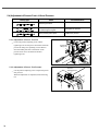
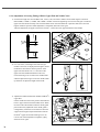
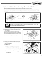
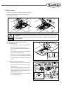
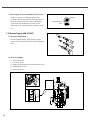
1
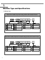
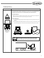
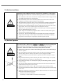
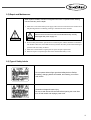
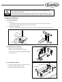
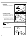
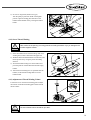
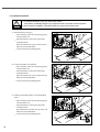
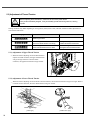
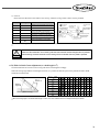
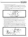
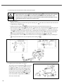
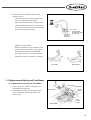
R
USER S MANUAL
KM-1750/1790
KM-1751/1791
Direct Drive, 2-Needle drop
feed (needle feed) sewing
machine with automatic
trimmer
lity
a
u
tQ
Besst Pricevice
Be st Ser
Be
1. Thank you for purchasing our product. Based on the rich expertise and
experience accumulated in industrial sewing machine production, SUNSTAR
will manufacture industrial sewing machines, which deliver more diverse
functions, high performance, powerful operation, enhanced durability, and
more sophisticated design to meet a number of user’s needs.
2. Please read this user’s manual thoroughly before using the machine. Make
sure to properly use the machine to enjoy its full performance.
3. The specifications of the machine are subject to change, aimed to enhance
product performance, without prior notice.
4. This product is designed, manufactured, and sold as an industrial sewing
machine. It should not be used for other than industrial purpose.
R
Contents
1. Machine Type and Specifications .............................................................................. 6
1.1) Machine Type .................................................................................................................... 6
1.2) Specifications ..................................................................................................................... 7
2. Safety Rules ......................................................................................................................... 8
2.1) Safety Stickers ................................................................................................................... 8
2.2) Machine Delivery .............................................................................................................. 9
2.3) Machine Installation ........................................................................................................ 10
2.4) Machine Operation .......................................................................................................... 10
2.5) Repair and Maintenance .................................................................................................. 11
2.6) Type of Safety Labels ...................................................................................................... 11
2.7) Location of Safety Labels ............................................................................................... 12
3. Assembly ............................................................................................................................ 13
3.1) Name of Machine Parts ................................................................................................... 13
3.2) Installation Environment ................................................................................................. 14
3.3) Machine Installation ........................................................................................................ 15
4. Machine Operation ......................................................................................................... 18
4.1) Lubrication ....................................................................................................................... 18
4.2) Test Operation (pedal operation) ..................................................................................... 19
4.3) Needle .............................................................................................................................. 20
4.4) Thread .............................................................................................................................. 20
5. Sewing Methods .............................................................................................................. 25
5.1) How to operate the machine ............................................................................................ 25
5.2) How to Conduct Backtack Sewing ................................................................................. 25
5.3) Adjustment of Thread Tension ........................................................................................ 26
5.4) Adjustment of Presser Foot s Lift and Pressure ............................................................ 28
6. Maintenance ....................................................................................................................... 29
6.1) Adjustment of Feed Dog Height ..................................................................................... 29
6.2) Adjustment of Needle and Hook Timing ....................................................................... 29
6.3) Adjustment of Distance Between Hook Stopper Face and Needle Plate Groove Face .......... 31
6.4) Adjustment of Distance Between Hook and Opener ..................................................... 31
6.5) Suspension of Needle Bars (left, right) (KM-1790 series) ............................................ 31
6.6) Adjustment of Trimming Devices .................................................................................. 34
6.7) Replacement of Moving and Fixed Blades .................................................................... 39
6.8) Adjustment of wiper ........................................................................................................ 40
7. Check and Confirm ......................................................................................................... 41
7.1) Regular Check Points ...................................................................................................... 41
7.2) Cleaning ........................................................................................................................... 41
7.3) Lubrication ....................................................................................................................... 42
7.4) Status Check .................................................................................................................... 43
7.5) Grease Supply (KM-1750SF) ......................................................................................... 44
8. Replacement of Stitch Length Gauge Set ............................................................ 45
8.1) Disassembly Order .......................................................................................................... 45
8.2) Assembly Order ............................................................................................................... 45
9. Cause of troubles and troubleshooting ................................................................ 46
Machine Type and Specifications
1.1) Machine Type
Direct drive 2-needle, drop feed sewing machine with automatic trimmer
Code
Lubrication Type
S Semi-Dry Type
Dry
Micro Lubrication Head
M
Type
0
1
Auto Lubrication Type
Code
Application
Code
Hook
Code
Trimming
F
Thin Materials
None
Standard Hook
None
None-Trimming
G
General materials
L
Large hook
7
Trimming
B
Heavy materials
Direct drive 2-needle, drop feed, feed needle sewing machine with automatic trimmer
6
Code
Lubrication Type
Code
Application
Code
Hook
Code
Trimming
0 M
Micro Lubrication Dry
Type
Head
G
General materials
None
Standard Hook
None
None-Trimming
1
Auto Lubrication Type
B
Heavy materials
L
Large hook
7
Trimming
1.2) Specifications
Direct drive 2-needle, drop feed sewing machine with automatic trimmer
KM-1750
Model
Item
KM-1751
SF
MG
MBL
BL
Usage
For Thin Materials
For General Materials
Lubrication
Semi-dry
Max. Sewing Speed
3,000 spm
4,000 spm
3,000 spm
Max. Stitch Length
4 mm
5 mm
7 mm
For Heavy Materials
Minute Lubrication Adjustment
Automatic Lubrication
33.4 mm
Needle Bar Stroke
Needle Take-up Stroke
52 mm
62.4 mm
Feed Dog Height
1 mm
Presser Foot Lift
7 mm(manual) / 15 mm(Lap) / 10 mm(automatic)
Hook
Standard Hook
Needle (DP 5)
#9~#14(#11)
Large Hook
#11~#16(#16)
#14~#22(#22)
Sewing Space
257 mm(W), 120 mm(H), 87 mm (arm jaw)
Bed Size
518 mm 178 mm
Thread Winder
Attached to sewing machine body (upper arm)
Automatic Trimmer
Standard feed
Automatic Backtack Device
Standard feed
Motor
AC servo motor (550W)
Power Supply
Single-phase (100~240V), 3-phase (200~240V, 50/60Hz)
Direct drive 2-needle, drop feed, feed needle sewing machine with automatic trimmer
KM-1790
Model
Item
KM-1791
MG
Usage
Lubrication
MBL
For General Materials
For Heavy Materials
3,000 spm
5 mm
7 mm
Needle Bar Switch
Split Needle Bar
Needle Bar Stroke
33.4 mm
Needle Take-up Stroke
Automatic Lubrication
Minute Lubrication Adjustment
Max. Sewing Speed
Max. Stitch Length
BL
52 mm
64.6 mm
Feed Dog Height
1 mm
Presser Foot Lift
7 mm(manual) / 15 mm(Lap) / 10 mm(automatic)
Hook
Standard Hook
Large Hook
Needle (DP 5)
#11~#16(#16)
#14~#22(#22)
Sewing Space
257 mm(W), 120 mm(H), 87 mm (arm jaw)
Bed Size
518 mm 178 mm
Thread Winder
Attached to sewing machine body (upper arm)
Automatic Backtack Device
Standard feed
Automatic Trimmer
Standard feed
Motor
AC servo motor (550W)
Power Supply
Single-phase (100~240V), 3-phase (200~240V, 50/60Hz)
7
Safety Rules
2.1) Safety Stickers
The safety stickers in this user’s manual are divided into Caution , Danger , and Warning . They indicate that if the
safety rules are not kept, injury or damage to machine might occur as a result.
No.
Name
Description
Caution
If the machine is not properly handled, it may cause injury to
users or physical damage to the machine.
Warning
If the machine is not properly handled, it may cause death or
severe injury to users.
Danger
If the machine is not properly handled, it may cause death or
severe injury to users, and the urgency of the danger is very
high.
Caution
Warning
Danger
8
2.2) Machine Delivery
Mark
Description
The machine delivery shall be conducted by the persons who are knowledgeable about
the safety instructions and rules. The following safety rules must be observed:
2.2.1) Manual delivery
When the machine is manually moved by workers, they are required to put on safety shoes
and firmly hold the machine on the left and right side of the table.
Danger
2.2.2) Forklift delivery
1) A forklift shall be big enough to endure the weight of the sewing machine and carry the
machine.
2) Use the palette when lifting the machine. Set the center of gravity of the machine (center
of the left and right sides) at the fork arm of the forklift and carefully lift the machine.
Ban people from
standing under the
machine and remove
obstacles near the
machine.
Warning
When the machine is moved by a forklift, a crane, or a transporting
device, the balance of the machine must be maintained in order to
prevent any deformation of the machine and injury of the workers.
9
2.3) Machine Installation
Depending on the installation environment, function errors, breakdown, or other physical
damage might result. Make sure to meet the following conditions for machine installation:
Caution
1) The workbench or table where the machine is installed should be durable enough to endure
the weight of the machine (see the name plate).
2) Dust and humidity are the cause of machine pollution and erosion. Please install an air
conditioner and conduct regular maintenance of the machine.
3) Install the machine at the place where it is not exposed to direct sunlight (if the machine is
exposed to direct sunlight for a long time, it may cause discoloration or deformation).
4) Secure the space around the machine. Place the machine at least 50cm away from the left,
right, and rear walls to secure sufficient space for maintenance activities.
5) Explosion risk : To prevent possible explosion, immediately stop the machine operation if
there are inflammable materials in the air.
6) Lights : Lights are not additionally supplied with the machine. If needed, install lights to
prevent any inconvenience during work.
7) Overturn risk : Do not install the machine on the unstable stand or table. If the machine
drops, it may cause injury or severe impact on the machine. If the machine is suddenly
stopped or the external impact is imposed, the machine might be capsized.
2.4) Machine Operation
The machine body is attached with Caution and Warning stickers at each dangerous
part to emphasize safety instructions. With the full understanding of the safety
instructions, make sure to observe the following during machine operation:
Warning
10
1) Before turning on the power, read this manual thoroughly and have a full understanding of
machine operation.
2) Get properly dressed. Long hair, necklace, bracelet, or wide sleeve might be fed into the
machine during operation. Wear slip-free shoes to prevent slipping on the floor.
3) Check the moving scope of machine before its operation to find out whether the scope is
proper.
4) Keep hands and head away from the machine parts where accidents might occur (needle,
hook, thread take-up lever, pulley, etc.) during operation.
5) Do not remove the safety cover which protects pulley and shaft during machine operation
for user s safety.
6) Cut the power supply before disassembling the electric box such as the control box, and
double-check that the power switch is Off.
7) Make sure that the power switch is Off when the upper shaft is manually rotated.
8) Stop the machine when the needle is replaced or when inspecting the machine after sewing
work is done.
9) Make sure to follow the cautions below. Otherwise, physical damage to the machine such as
malfunction and breakdown might result:
Do not put articles on the S/M table.
Avoid using a crooked needle or the needle with damaged tip.
2.5) Repair and Maintenance
When repair is needed, SunStar A/S engineers who have completed certain training
course must carry out the repair.
1) Make sure to turn off the main power supply and wait for four minutes for the machine to be
fully discharged before conducting cleaning or maintenance of the machine.
Servo motor and control box need 10 minutes before they are fully
discharged after power supply cut.
Danger
Caution
2) Do not modify the machine specifications or machine parts without substantial consultation
with SunStar. Otherwise, the modifications may threaten the safety of the machine during its
operation and cause safety accidents.
3) Make sure to use SunStar's original parts for repair and parts replacement.
4) When the repair is completed, put back all the disassembled safety covers.
2.6) Type of Safety Labels
Do not operate without finger guard and safety devices. Before
threading, changing bobbin and needle, and cleaning, turn off the
main switch.
Hazardous voltage will cause injury.
Be sure to wait at least 360 seconds before opening this cover after
turn off main switch and unplug a power cord.
11
2.7) Location of Safety Labels
12
Assembly
3.1) Name of Machine Parts
3.1.1) Name of Machine Parts
Thread winder
Reverse button
Lap lift lever
Reverse lever
O/P panel
Safety devices
Thread take-up cover
Wiper Device
Presser foot
Power switch
Stitch length dial
Thread Stand
Presser bar lifting lever
Control box
Oil window
S/M pulley
Finger guard
Motor cover
13
3.2) Installation Environment
3.2.1) Installation Environment
1) To prevent accidents stemming from mal-operation, do not use the machine if the voltage is 10% above the rated
voltage.
To guarantee smooth operation of the product, the installation environment shall be prepared as
described in User’s Manual. Otherwise, unexpected damage might occur to the product.
Caution
2) Proper temperature during machine operation
: 0 ~ 40 C (32 ~ 104 F)
3) Proper temperature during machine storage
: 25 ~ 55 C ( 13 ~ 131 F)
4) Humidity : Relative humidity
– within 45 ~ 85%
3.2.2) Electricity Environment
Warning
The voltage of the power supply should move within the range of 10% of the rated voltage. Insert
the power plug of the sewing machine directly into the AC outlet. If an extension cord is used, it
may cause mal-operation of the sewing machine.
1) Power voltage
The power voltage shall be within 10% of the rated voltage.
It is recommended to use the power frequency within 1% of the rated frequency (50/60Hz).
2) Noise of electromagnetic wave
Do not install the sewing machine next to a TV, a radio, or a cordless phone. The machine may be interfered by a
TV, a radio, or a cordless phone.
3) Take care not to spill water and coffee on the machine.
4) Do not drop Control Box and the motor to the floor.
14
Caution
1) To prevent safety accidents, at least two persons should be involved in the installation and
transportation of the machine.
2) It is recommended to use the table supplied by SunStar. If the table is internally made, the table
should be at least 40mm thick and durable enough to support the weight of the sewing machine.
3.3) Machine Installation
3.3.1) Table Installation
1) Table Fixing
Insert the shock-absorbing rubber into the level adjuster and turn it until the caster can move freely.
Fasten the nuts after table installation and fix the level adjusters.
2) Adjustment of Table Height
Use the bolt attached to the table to adjust its height to the level that enables convenient work for the users.
Bolt
Nut
Level Adjuster
Shock-absorbing
Rubber
Caster
3.3.2) Installation of Control Box
1) Location of Control Box and Petal
Install the bracket, the pedal switch, and the
connection rod, and then properly adjust the length of
the connection rod.
3.3.3) Installation of Oil Pan
1) Attach four cushion rubbers to the corners of the oil
pan and install the oil pan to the table.
2) Insert the lap lifting cap into the oil pan.
Lap Lifting Cap
Cushion Rubber
15
3.3.4) Hinge Rubber
1) Install two hinge rubbers on the table, and use nails
to fix them on the table.
Hinge Rubber
3.3.5) Assembly of Sewing Machine
1) Insert two hinges firmly into the holes of the rear
side of machine bed.
2) Put machine body on the rubber cushion , while
putting hinges on the hinge bed rubber safe and
sound.
3) Insert the machine body sustaining pole into table
completely. If the pole is not inserted completely,
that may cause accidents because the pole cannot
sustain the weight of machine body firmly, when the
body bent backwards.
rubber cushion
sustaining pole
hinges
hinge bed rubber
Caution
1) At least two persons shall be involved in the assembly of the sewing machine body to the table
for safety.
2) When the body is leaned backward, if the support bar shakes, safety accidents may occur.
3.3.6) Operation Panel
Assemble the operation panel to the bracket, and attach
them on the rear side of the machine body.
16
3.3.7) Thread Stand
Assemble the thread stand and install it on the table.
Then adjust the location of the thread stand for
convenient use.
3.3.8) Lap Lifting Plate
1) Install the lap lifting plate below the oil pan and use
the bolts to fix it.
2) Use the location adjusting bolt of the lap lifting plate
to move it to the proper location.
Lap Lifting Plate
3.3.9) Adjustment of Presser Foot Height
1) Turn the pulley to locate the feed dog below the needle plate.
2) When the presser foot is in the upper position, adjustment is impossible. Pull down the presser bar lifting lever to
lower the presser foot.
3) Use the adjusting screw to adjust the height of the presser foot from 10mm, the standard height, to 15mm, the
maximum height.
Presser bar lifting lever
17
Machine Operation
4.1) Lubrication
Warning
Caution
1) Until oil supply is completed, do not insert the power plug into the outlet.
If the power is supplied and the pedal is accidentally stepped, injury might occur due to
unintended machine operation.
2) When handling lubricant, put on safety glasses and gloves. Take extra care to prevent lubricant
from touching eyes and skin.
When lubricant contaminates hands, wash it out in running water using soap.
If lubricant contaminates eyes, immediately wash them out in running water and see a doctor.
3) Do not drink lubricant. It may cause diarrhea and vomiting.
If you drink lubricant, immediately see a doctor.
4) Keep lubricant in a safe place away from the reach of children and youth.
1) At the first use of the sewing machine after purchase or when the machine is used after it has not
been used for a while, oil supply is required.
2) Use the SunStar’s original lubricant products (lubricant is in the accessory box).
3) When supplying lubricant, check the supplied volume to make sure that lubricant will not overflow.
4.1.1) Lubrication
Lean backwards the sewing machine and supply
lubricant using the lubricant can until the punched
mark of the oil cover.
Use the lubricant supply can which is located in the
accessory box to supply lubricant into the oil tank.
Remove the rubber cap and supply lubricant until it
reaches between the up and down punched marks on
the oil window.
During lubrication, insert the outlet of the oil can into the oil cover to prevent oil spilling on the floor.
Caution
18
4.1.2) Others
Use the lubricant can to supply two to three drops of
lubricant around the oil wick and felt.
Note
1) Arm lubrication : Disassemble the face plate, and lubricate the major friction areas of the parts
including the thread take-up hinge pin, the needle bar frame, the thread take-up
holder, the thread bar crank, and the guide block.
2) Bed lubrication : Lower shaft’s front bushing, lower shaft s middle bushing felt, hook support’s
gear felt
4.1.3) Oil supply(KM-1751/1791 Series)
1) Installing chip remover magnet
Attach the magnetic chip remover that is in the accessory box to the oil fan.
Do not use the magnet for other purposes. Use of the sewing machine without the magnet may
cause malfunction and has a bearing on the machine’s durability.
Caution
2) Lubricating the oil fan
A. Fill the lubricant up to the “HIGH” mark.
B. The lubricant must be SUNSTAR’s oil provided
exclusively for industrial sewing machines or
SHELL’s Tellus C10.
C. If the oil in use is down to the “LOW” mark, fill
in to “HIGH” immediately.
D. Once every two weeks is deemed the appropriate
interval for oil refills.
magnet
4.2) Test Operation (pedal operation)
Do not touch or press with objects the moving or spinning parts of the sewing machine, while it is in
operation. It may cause injury or damage to the machine.
Caution
19
1) Lightly press the pedal in the B position to make sure
that the low speed sewing is properly conducted.
2) Press the pedal until the C position to check whether the
high-speed sewing is properly conducted.
3) Press the pedal forward (B or C position) and release the
pedal to locate it at the neutral (A) position. And check
whether the needle stops below the needle plate s front
side (in case where the lower-position needle stop is set).
4) Press the pedal at the D position (Press the pedal to D and
move it to the neutral (A) position). Then after trimming,
the needle stops above the front side of the needle plate.
4.3) Needle
1) Turn off the power stitch when installing the needle.
2) If the pedal is accidentally stepped, it may cause injury or accident.
Caution
4.3.1) Needle Installation
1) Turn the pulley to place the needle bar at the highest
position.
2) Place the needle’s groove headed inward and
thoroughly push the needle until its end touches the
stopper, and then fasten the needle with the fixing
screw.
KM-1750 Series
4.4) Thread
Turn off the power switch to separate the bobbin case.
If the pedal is accidentally stepped, it may cause injury.
Caution
4.4.1) Separation of Bobbin and Bobbin Case
1) In case of a regular hook (Latch type)
Turn the pulley to place the needle at the highest
position. Open the sliding plate and remove the
bobbin by erecting the bobbin holder.
20
KM-1790 Series
2) In case of a large hook (bobbin case type)
Turn the pulley to place the needle at the highest
position. Open the sliding plate and remove the
bobbin and the bobbin case by erecting the bobbin
holder.
4.4.2) Lower Thread Winding
Take caution for the spinning or moving parts when winding the bobbin. Injury or damage to the
machine might be caused.
Caution
1) Insert the bobbin into the thread winding shaft on the
winding base, which is attached to the upper arm.
2) Wind the thread around the bobbin several times, and
lift the presser bar by using the presser bar lifting
function.
3) Attach the thread winding lever to the bobbin and
press the pedal to wind the thread around the empty
bobbin.
4) After the thread winding lever is separated from the
bobbin, use the thread winding blade to cut the
bobbin thread.
4.4.3) Adjustment of Thread Winding Volume
Loosen the screw on the thread winding plate to adjust
the location of the thread winding plate and the wound
thread volume.
The wound thread volume should be up to 80%.
Caution
21
4.4.4) Bobbin Installation
Caution
1) To separate the bobbin case, turn off the power switch.
1) If the pedal is accidentally stepped, injury might result due to unwanted machine operation.
2) Upon the bobbin installation, insert the anti-spinning spring into the bobbin case.
1) Standard hook (Latch type)
Upon trimming, insert the anti-spinning spring
into the bobbin case.
Install the bobbin on the hook in the thread
winding direction.
Move the thread to the A part of the hook and
make the loose thread 50mm.
Close the left and right sliding plates.
2) Large hook (bobbin case method)
Upon trimming, insert the anti-spinning spring
into the bobbin case.
Install the bobbin on the hook in the thread
winding direction.
Move the thread to the A part of the hook, and
make the loose thread 50mm.
Close the left and right sliding plates.
3) Feeding each needle (bobbin case method) (KM1790)
Upon trimming, insert the anti-spinning spring
into the bobbin case.
Install the bobbin on the hook in the thread
winding direction.
Pass the thread in the order of A, B, and C, and
make the loose thread 50mm.
Close the left and right sliding plates.
22
Anti-spinning Spring
4.4.5) Routing the lower thread
[ Applicable Models ]
a) KM-1750 MG
b) KM-1750 MBL
A. Insert the bobbin into the hook .
B. Insert the thread through A part of the hook
, and pull it out from the end of the lower
thread tension adjustment plate .
C. The adequate length of the pulled-out lower
thread is 50mm.
( Application Standard )
KM-1750 MBL
[ Applicable Models ]
a) KM-1790 MG
b) KM-1790 MBL
A. Insert the bobbin into the bobbin case .
For KM-1790 MG, it is crucial to insert the
bobbin in the turning direction as in the
picture.
B. Insert the thread through A part of the
bobbin case, and pull it out from the end of the
lower thread tension adjustment plate .
C. Pass the pulled-out thread through B and
C of the bobbin case, as can be seen on the
picture, and hang it onto the lower thread
holding spring . Then pull it out through the
thread hole .
D. The adequate length of the pulled-out lower
thread is 50mm.
(Application Standard)
KM-1790 MBL
23
4.4.6) Upper Thread Placement
When separating the bobbin case, turn off the power switch.
If the pedal is accidentally stepped, and the machine begins operating, injury might occur.
Caution
Turn the pulley to locate the thread take-up lever at the
highest position, and place the upper thread. Place the
left-hand thread first.
4.4.7) Using Lap Lifting Pad
The presser foot can be lifted or lowered using the lap
lifting pad.
24
Sewing Methods
Caution
1) Make sure to keep all safety devices on their place to prevent any injuries.
2) Please turn off the power switch in the following situations where accidental stepping of the
pedal might cause injuries.
Replacement of bobbin and needle and upper thread placement
When the machine is left unused for a long or temporary leaving while the machine is in
operation
5.1) How to operate the machine
1) Pull the two strands of upper threads with a hand and
turn the pulley until the lower thread moves above the
feed dog.
2) Pull the upper thread toward the direction of the user and
check whether the lower thread is smoothly released.
3) Press the power button ( On button) to make the panel
lamp on and the sewing machine ready for operation.
4) Set the operational panel based on the user s manual of
Fortuna IV.
5) The machine is ready to work. It will start sewing when
the pedal is pressed.
Power Switch
5.2) How to Conduct Backtack Sewing
1) During sewing, if the reverse switch or the reverse
lever is pressed, the sewing materials will move
backwards. Otherwise, they will move forward.
25
5.3) Adjustment of Thread Tension
Caution
Before adjusting the thread tension, make sure to turn off the power switch.
If the pedal is mistakenly stepped, it may accidentally operate the sewing machine, causing
injuries.
Sewing conditions may differ depending on sewing fabric, thread, stitch count, and other conditions. Make adjustments in
line with the table below:
Sewing Type
Cause
Actions
Balanced good stitch
When the upper thread tension is too weak
or the lower thread tension is too strong
Strengthen the upper thread tension or
weaken the lower thread tension
When the upper thread tension is too strong
or the lower thread tension is too weak
Weaken the upper thread tension or
strengthen the lower thread tension
5.3.1) Adjustment of Upper Thread Tension
When the tension adjusting nut for the thread tension
adjuster is turned clockwise, the upper thread tension
will get stronger. When it is turned counterclockwise, the upper thread tension will get weaker.
5.3.2) Adjustment of Lower Thread Tension
When the tension adjusting nut for the hook is turned clockwise, the lower thread tension will grow stronger. When it
is turned counter-clockwise, the lower thread tension will grow weaker.
Weaker
Stronger
[ Latch Type ]
26
[ Bobbin Case Type ]
5.3.3) Adjustment of Thread Take-up Lever Spring
1) Adjustment of Thread Take-up Spring Motion
Loosen the tightening screw for the stopper, and
adjust the spring stopper to adjust the spring motion
(The thread take-up spring lever moves in the range
from 5 to10mm).
2) Adjustment of Thread Take-up Spring Tension
Loosen the screw on the thread adjusting shaft.
When the groove on the thread adjusting shaft is
turned clockwise using a driver, the thread take-up
spring tension grows stronger. When it is turned
counter-clockwise, the tension grows weaker (The
standard tension is 30~70g).
5.3.4) Adjustment of Thread Release Motion
(automatic trimming)
If the upper thread escapes from the needle hole after
trimming, adjust the opening of the dish as below.
Activate the thread release solenoid and adjust the
solenoid shaft collar back and forth to set the opening of
the thread tension adjusting dish at 0.8mm.
If the thread release solenoid is not in operation, check
whether the dishes are closely contacted.
If the dishes are not properly separated despite their proper assembly, check the front face of the
control box to see if the remaining upper thread adjustment volume is set at the low level.
Caution
5.3.5) Adjustment of Auxiliary Thread Adjuster
(automatic trimming)
Adjust the auxiliary thread tension adjusting nut to set
the remaining upper thread to be 35~45mm.
The adjustment can be made using the remaining upper thread length adjustment volume on the
control box.
Note
27
5.4) Adjustment of Presser Foot’s Lift and Pressure
Sewing Type
Cause
Corrective Actions
Balanced good stitch
When stitch skip takes place or when
the stitch length is irregular
Strengthen the pressure
When puckering takes place
Weaken the pressure
5.4.1) Adjustment of Presser Foot Lift
Loosen the pressure adjusting screw and the
tightening screw for the presser bar bracket. With the
presser bar lifting lever pulled up, set the distance
from the needle plate face to the bottom of the
presser foot at 7mm, and fasten the bracket
tightening screw.
5.4.2) Adjustment of Presser Foot Pressure
Use the pressure adjusting screw to adjust the presser
foot pressure.
When the adjustment is completed, fasten the fixing
nut.
28
Presser Bar
Lifting Lever
Pressure
Adjusting Screw
Maintenance
1)
2)
3)
4)
Caution
Skilled engineers should carry out repair and maintenance of the sewing machine.
When electric repair and maintenance is needed, request the distributor shops or electricity experts.
If the safety devices are separated, make sure to put them back into their original places.
Use both hands to lead backward the sewing machines or place it back to the original place.
If only one hand is used, due to the weight of the machine, the hand might be stuck or other injury
might occur.
5) In the following cases, turn off the power switch and pull off the power plug. If the pedal is
accidentally stepped, unwanted operation of the sewing machine might occur, causing injuries.
Regular check, maintenance, repair
Replacement of supplies such as needle, hook, and blade
Adjustment of lubrication to the hook
6) If adjustment is made when the power switch is on, take extra care to secure safety.
6.1) Adjustment of Feed Dog Height
Turn the pulley to place the feed dog at the highest position.
Then loosen the tightening screw for the feed dog support to
move it up and down. Adjust the feed dog to protrude some
1mm from the needle plate face in parallel.
Feed Dog
1mm
6.2) Adjustment of Needle and Hook Timing
6.2.1) Adjustment of Up/Down Needle Bar Position
1750 Series
2.4mm
2.4mm
Turn the pulley to place the needle bar at the lowest position. Loosen the tightening screw for the needle bar holder to
place the punched mark of the needle bar at the end of the frame. When adjustment is completed, fasten the tightening
screw for the needle bar holder again.
1790 Series
29
6.2.2) Adjustment of Crossing Timing of Hook’s Upper End and Needle Center
2.4mm
1.5mm
1) Set the stitch length at 2.5mm for KM-1750, 1750-7, 1790, and 1790-7 models. Set the stitch length at 3.5mm for
KM-1750BL, 1750BL-7, 1790BL, and 1790BL-7 models. Loosen the tightening screw for the hook gear to make the
upper end of the hook accurately meet with the needle center when the needle bar is placed 2.4mm above from the
highest needle bar position. When adjustment is completed, fasten the screw again.
After the adjustment, the upper hook will be located 1~1.5mm above the upper thread hole of the needle.
2) For 1790 series, if the height of the left and right
needles is not same, as displayed in the figure, lift the
needle bar 2.4mm from its lowest position. If the
upper end of the hook is not 1~1.5mm above the
upper end of the needle thread hole in this case,
loosen the fixing screw to remove the needle holder
and then adjust the fixing screw for the needle holder
up and down to adjust the height of the needle.
3) Adjustment of Distance Between Needle and Hook s
Upper End
Lift the needle from the lowest position and make the
hook s upper end meet with the needle center. When
the lower end of the needle touches the needle guide
plate of the hook (adjustment of the needle guide s
configuration), loosen the screw and move the hook
support left and right to adjust the distance between
the hook s upper end and the needle groove to be
0.05~0.1mm. When adjustment completes, tightly
fasten the screw again.
30
6.3) Adjustment of Distance Between Hook Stopper Face and Needle Plate Groove Face
The standard distance between the hook stopper face and the needle plate groove face is 1.3mm.
This distance can be adjusted using the thickness of the space washer which is located below the hook. Loosen the fixing
screw for the hook gear to separate the hook and insert the space washer which is initially assembled status after repair or
replacement.
Space Washer
Fixing Screw for
Hook Gear
Depending on machine model, the washer in use may have different thickness. As such, make
sure to use the initially assembled space washer.
Caution
Loosen the tightening screw for the opener to set the
distance between the hook and the opener at 0.2mm when
the opener is pushed at the maximum in the arrow direction,
and adjust the left and right sides of the opener.
0.2mm
6.4) Adjustment of Distance Between Hook
and Opener
Opener
Tightening
Screw
Hook
6.5) Suspension of Needle Bars (left, right)
(KM-1790 series)
6.5.1) Button Use
1) Suspension of Left/Right Needle Bars (when
conducting corner sewing at left/right sides)
Press the needle bar switch of the desired spinning
direction and then the concerned button lamp blinks.
2) Switch to 2-Needle Sewing
Press the switch button which is blinking again to
cancel the setting.
Suspend
Suspend
31
6.5.2) Program Application (for semi-automatic corner sewing)
The model equipped with E-Type controller can carry out program-guided corner sewing.
Note
For semi-automatic corner sewing, necessary data and code numbers should be entered into the program box in advance.
To switch from general sewing to corner sewing, press a desired left needle or right needle button and press the pedal
once. Then the concerned needle will stop at the highest position and the opposite needle will stop after sewing the predefined number of stitches. Set the sewing fabric at the different angle and step the pedal again. Then the needle bar stops
after sewing the pre-defined number of stitches. At the third pressing of the pedal, the suspended needle at the highest
position will be automatically released, and the regular two-line sewing will be conducted.
6.5.3) Programming Order
Have a thorough understanding of program entry methods from the electric/electronic manual, and
conduct programming using the default values of A group codes from #30 to #36.
Note
1) Call Code# 30 and enter 1 as the default value.
When 1 is entered, the semi-automatic corner sewing can be conducted. When 0 is entered, the function cannot be
conducted.
2) Call Code# 31 and set the sewing speed for corner sewing.
The speed can be freely adjustable at the range of 24spm to 2040spm.
3) Corner sewing Direction Setting
Left corner sewing
When the left needle stops at the highest position, enter 32 as the first sewing stitch count for the right needle, and
enter 33 as the second sewing stitch count.
Right corner sewing
When the right needle stops at the highest position, enter 34 as the first sewing stitch count for the left needle, and
enter 35 as the second sewing stitch count for the left needle.
Note
The number of stitches for left and right needles ranges from 0 to 64.
Conduct the programming as set forth above and operate the machine following the semiautomatic corner sewing method as explained above. Then the semi-automatic corner sewing will
be repeated using the pre-entered data.
4) Code# 36
To protect the left and right solenoids, the automatic power-off time after their operation is completed can be set.
The default value is 450(45 seconds) and it can be set at the range of 5(0.5 seconds) to 1275 (127.5 seconds).
32
5) Exercise
Please enter the data below and conduct corner sewing. Then the sewing results as below will be produced.
Initial configuration
What it means
30
1
Whether or not semi-automatic corner work will
be carried out
31
1500
Code No.
32
2
33
1
34
5
35
5
36
450
Right needle upstop position
First round number of
stitches (5 stitches)
Speed of semi-automatic corner work
First round no. of stitches for the right needle
when the left needle is in up-stop position
Second round no. of stitches for the right needle
when the left needle is in up-stop position
First round no. of stitches for the left needle
when the right needle is in up-stop position
Second round no. of stitches for the left needle
when the right needle is in up-stop position
Left needle up-stop
position order
Rig
h
stop t need
pos le up
Sec
ition num ond rou
(5 s ber of nd
titch stitc
hes
es)
Left needle up-stop
position
First round number of
stitches (2 stitches)
Left needle up-stop position
Second round number
of stitches (1 stitch)
Right needle
up-stop position order
Left and right needle solenoid waiting time
Details: Corner sewing speed is 1500 spm, and the retention time of left/right solenoids is 45 seconds.
When the semi-automatic corner sewing data has been entered and the left/right button is pressed
before sewing, the semi-automatic corner sewing will be conducted when the pedal is pressed.
Caution
6.5.4) Table for Stitch Count Adjustment (ex: stitch length 1/4 )
See the beside table for accurate corner sewing and set the stitch length accordingly.
When the sewing angle and the stitch length are known, it is possible to find out by how many stitches the outer needle
should be moved forward.
No. of
stitches
sewing
angle
No. of
stitches: 6
Working
angle 40
[ left turn sewing ]
When the sewing angle is 40 and the stitch length is 2.9mm, the outer needle should move straight forward by six stitches.
33
6.6) Adjustment of Trimming Devices
6.6.1) Adjustment of Trimmer Driving Part
1) Trimmer Cam Location
Turn the pulley by hand to locate the needle bar
at the lowest position.
Put the trimmer cam and the lower-shaft middle
bushing closely together and turn the cam to
make punched marks meet each other. Then
fasten the tightening screw.
Needle
Bar
Fixing Screw
Lowest
Point
Lower-Shaft Punched Punched Trimmer
Mark
Middle Bushing Mark
Cam
When the trimmer cam position is adjusted, turn the pulley by hand to check whether it rotates
smoothly.
Caution
2) Adjustment of Stopper Pin Holder
Turn the pulley to place the trimmer cam within the scope of the complementary straight line.
Insert the trimmer oscillator link fully into the roller and adjust the holder to ensure the close contact between the
trimmer oscillator link and the right side of the roller.
Adjust the holder to ensure the close contact between the stopper pin and the left side of the stopper pin holder.
Stopper Pin Holder
Close Contact
Roller
Stopper Pin
Fixing Screw
Trimmer Oscillator Link
Complementary Straight Line
Point of Trimming
Completion
Roller
Close Contact
Trimmer Cam
(
The current stop position of the cam indicates that the
cam guide is within the complementary straight line
before the roller is removed after trimming.)
Point of Moving
Blade Motion Start
[ Trimmer Cam Guide ]
When the stopper pin holder adjustment completes, if the trimmer oscillator does not move
smoothly, minute adjustment of the holder is required.
Caution
34
3) Fixing the position of the trimmer solenoid (ass y) (See figure)
When the whole trimmer shake linkage is in up position, that is, when it has come back to its original position
after finishing trimming, the distance between the lower part of the roller and the equal point of the trimming
cam is about 0.8~1mm. Assuming that this distance never changes, adjust the position of solenoid bracket
horizontally, where the solenoid housing is attached, to make the solenoid stroke 4 mm. Then, tightly fasten
with fixing screw .
After adjusting the solenoid stroke , manually operate the solenoid shaft towards the arrow direction. See
whether it returns to its original position fast and smooth when released. If not, proceed with horizontal
adjustment of the bracket .
4mm
Solenoid Stroke
0.8mm~1mm
6.6.2) Adjustment of linking device for movable knife shaft and the trimmer driving part (See figure)
1) When the previously explained adjustment of trimmer driving part is complete, it is in its normal position where the
trimmer shake linkage has returned to its up position after trimming action.
2) First, loosen the fixing screw of the movable knife shaft (right), hold the initial assembling angle of the crank (right)
to be about 15 , 30 to the left from the perpendicular line drawn to its center . To make sure that this
position is maintained, adjust the length of the ball joint linking bar which comes assembled to trimmer shake
linkage . Also, adjust the fixing screw tightly.
(For the adjustment of the ball joint linking bar , turn the linking bar after loosening the nuts (left) and (right)
. is left nut and is the right nut.)
3) Then, loosen fixing screw of the movable knife shaft crank (left) , and in the same angle as the crank(right) s
lower assembling angle , place the crank(left) . Tightly fasten the fixing bolt to make sure this position holds.
4) When the linking device is connected as such, the movement angles , , , of crank (left) and (right)
during trimming movement results in an equal angle movements for left and right, against the perpendicular lines
and that are drawn from the center line of the two movable knife shafts. Hence, it can be said that the trimming
movement is very light.
35
6.6.3) Adjusting movable and fixed knives
1) Adjusting the position of movable knife-edge and hook stopper (See figure)
When a movable knife passes the front side of the hook stopper , adjust the distance to be within 0.05~0.2
mm range like part . The upper surface of the movable knife-edge should be set up 0.2mm below the upper
side of hook stopper . (Given that the fixed knife is pressing down the movable knife)
Clearance adjustment of the movable knife edge and hook stopper front side
Loosen the needle plate
Place the hook stopper in the hanging position to the needle plate
Holding the hook with the hand, manually operate trimming movement so that the movable knife-edge is
matches the stopper front side .
Loosen the fixing screw of the movable knife shaft eccentric bushing.
In the lower side hole of the eccentric bushing , stick in a thin driver or adequate pin and turn right and
left. This will make the position of the movable knife shaft change, hence changing the distance .
When the clearance adjustment is finished, tightly fasten the fixing screw of the bushing.
The adjustment of crossing height between the hook stopper upper side and movable knife edge upper side
is possible to certain degree by adjusting the movable knife base washer or by changing the position of
movable knife shaft collar , as can be seen in figure.
0.2mm
0.05mm~0.2mm
36
2) Adjusting movable and fixed knife (See figure)
Like in figure, adjust the position of the fixed knife so that the fixed knife right side edge matches the
movable knife inner side edge .
The initial assembling position of the movable knife is where the movable knife-edge protrudes about 3 mm
from the edge of the fixed blade. Please check the final fixing of the movable knife initial position on page 38.
The surface adhesion conditions of fixed blade edge and movable knife upper side have huge impact on its
trimming capacity. Please note the various cases of movable/fixed knife surface adhesion conditions on the picture.
[Correcting the adhesive conditions of movable and fixed knives]
Like in figure, operate manual trimming movement with magic ink on the movable knife-edge. By checking
the ink trace remaining on the movable knife, the surface adhesion condition of the movable/fixed knives can
be tested.
If the surface adhesion is not very good (same method is used to adjust the tension of movable/fixed knives),
please use the following methods: adjusting the amount and position of the washer in the lower side of the
movable knife base , horizontally adjusting the assembling position of movable knife shaft collar , and
correcting the shape of fixed blade setting position.
3mm
[ Checking the
surface adhesion ]
Apply magic ink on the
upper side of the movable
knife-edge
(good)
(bad)
(bad)
37
3) Final fixing of the movable knife’s initial position (See figure)
Caution
The standard initial assembling position of the movable knife is where the movable knifeedge protrudes about 3mm from the fixed blade edge when the trimming action is finished,
that is, when the movable knife is in its initial stop position. When fixing the position of the
movable knife, the following directions must be followed so that the power generated in the cam
is delivered without any loss to the trimming action.
trimming
finish point
complementary
straight line
3mm
[Movable knife initial
assembling position]
4) Adjusting lower thread holder (See figure)
The position of lower thread holder is set by fixed
blade and bolt . Like in the picture, loosen the
bolt and place the lower thread holder edge at
the lower side of the movable knife , about 8mm
apart from the movable knife edge . Make sure to
of the
check that the right and left upper sides
lower thread holder is tightly adhered to the lower
side of the movable knife.
38
3mm
8mm
starting point of
movable knife
movement
[Trimming cam lead]
[ Adjustment Order ]
Manually turn the pulley to finish trimming of the trimming cam . Place the cam so that the roller can enter the
complementary straight line .
Slightly loosen the fixing screws
of movable knife shaft crank of both the left and the right.
Press the trimmer shake linkage to enter the roller inside the cam. Push the linking bar to the right or the
left crank linking rod to the left so that there is no excess room in each linking device. When this is done, the
roller gets to adhere to the right side of the cam s complementary straight line , as can be seen in the picture
. While maintaining this position, adjust to make the movable knives on the right and the left protrude about
on both sides.
3mm from the fixed blade-edge . Now, tightly fasten the crank fixing screws
If the initial position of the movable knives of both sides are to be adjusted slightly, use the ball joint linking bar
. If only the movable knives are to be adjusted, use the linking rod .
5) Checkpoints on the assembling status of other
trimming devices
Check the starting point of the movable knife
when the trimming action takes place
Operate trimming movement manually to check
whether the thread take up lever is in the lowest
or at least 2.5 mm raised level when the movable
knife starts working, like in figure.
0~2.5mm
Point where the
movable knife starts
Thread take its movement
up lever’s
lowest point
Maintenance of fixed blade
When the thread does not get trimmed or if the
trimmed section of the thread is sloppy, please
check the edge condition of the fixed blade.
If the edge of the knife is too dull, sharpen the
edge using oil stone or sand paper. (See figure)
60
OIL STONE
60
SAND PAPER
6.7) Replacement of Moving and Fixed Blades
6.7.1) Replacement of Moving and Fixed Blades
1) Lift the presser foot, open the sliding plate, and
disassemble the needle plate.
2) Disassemble the washer, the fixed blade, and the
lower thread holder, and then disassemble the
moving blade.
Presser Foot
Moving Blade
Needle Plate
Moving Blade
Fixed
Blade
Lower
Thread
Holder
39
6.8) Adjustment of wiper
about 0.3 mm
about 0.3 mm
about
0.3 mm
1) Set the needle (at the needle position on the control after trimming)
2) Set the stitch length at dial 2 .
3) When pressing with hand as in the picture, the wiper edge should protrude about 0.3 mm from the needle edge.
Loosen the four clamp screws to vertically adjust the solenoid .
4) Hang the thread onto the two needles.
5) The position of the wiper edge should look like the picture , where the two hooks of the wiper can securely hang
the thread. To do so, loosen the clamp screws of the wiper and horizontally adjust the wiper .
about 0.3 mm
6) When the wiper is in waiting position, the distance between the wiper edge and the presser bar equal point
should be about 3 mm. To do so, loosen the clamp screw and vertically adjust the stopper .
Depending on the thread type, there are cases where the thread cannot be hung to the wiper edge. Hence, it is
necessary to bring the wiper into the range of the needle where the thread from the sewing material can be hung.
Make sure that the needle fixing screw does not get in the way of the wiper.
0.5~1mm
7) The trace of wiper edge is as the above picture. Adjust the wiper edge by loosening the clamp screw
vertically adjusting the distance between the needle edge and wiper to 0.5~1mm.
40
and
Check and Confirm
Caution
Warning
1) Observe the mechanic and electric safety rules during the check and maintenance of the
machine.
2) Conduct lubrication while the machine power is off.
1) Do not insert the power plug into the outlet until the lubrication completes.
While the power is supplied, if the pedal is accidentally stepped, and unwanted machine
operation results, it may cause injuries.
2) When handling lubricant, put on safety glasses and gloves to protect skin and eyes.
When lubricant contaminates hands, wash it off in running water using soap.
If lubricant is inserted into the eyes, wash it off immediately in running water and see a doctor.
3) Do not drink lubricant. It may cause diarrhea and vomiting.
If lubricant is mistakenly drunk, immediately see a doctor.
4) Keep lubricant in a safe place out of the reach of children and youth.
5) Use two hands when leaning the sewing machine backward or placing it back to the original
position. If only one hand is used, it may slip away from the machine due to the weight, and it
may be stuck inside the machine.
7.1) Regular Check Points
1) Cleaning, lubrication, and grease supply for particular areas should take place on a regular basis to keep the machine at
the best conditions.
2) Check the tension of each driving belt.
3) When the regular checks are not properly performed, the following problems might result.
Abnormal abrasion of the oiled parts due to the lacking supply of lubricant and grease
Abnormal operation due to the dust and foreign materials stuck around the driving parts
4) If the machine was left unused for a long time, resume its operation after cleaning and maintenance activities.
7.2) Cleaning
7.2.1) Cleaning Frequency and Method
1) Make sure to turn off the power of the machine before cleaning.
2) The parts disassembled for cleaning should be assembled in the reverse order of disassembly.
Caution
NO.
Required Parts for Cleaning
1
Around Hook
2
Thread take-up lever / thread tension adjusting device
3
Around the moving and fixed blades
Remove the dust from the moving and fixed blades located below the
needle plate using air.
4
Treatment of Waste Oil
Cleaning Frequency
Daily
Once a week
Three times a week
Once a month
41
7.2.2) Cleaning
1) Place the needle at the highest position.
2) Disassemble the bobbin after opening the left and
right slide plates.
3) Use the soft brush, etc. to remove dust from the hook
and the feed dog.
4) Remove the bobbin after the cleaning completes.
7.3) Lubrication
7.3.1) Lubricant
Use the original SunStar s lubricant in the accessory
box.
7.3.2) Oil Tank Fill-up
Remove the rubber cap and supply oil until the full mark
on the oil window.
7.3.3) Oil Cover Fill-up
Lean backwards the sewing machine and check the oil in
the oil cover. Supply oil until the full mark.
42
7.4) Status Check
1) Replace the needle if it is deformed or the tip is damaged.
2) Check whether the upper thread is properly placed.
3) Conduct the test sewing.
Caution
1) Upon lubrication, make sure that lubricant does not overflow. Check the supply volume during
lubrication.
2) Lubricant shall not move above the Full mark on the oil window. Otherwise, lubricant leakage
may take place.
7.4.1) Adjustment of Lubrication to Hook
1) Oil Amount Check
Turn off the power and remove the thread from
the needle and the thread take-up lever.
Remove the needle and the bobbin and lift the
presser foot.
Turn on the power and run the sewing machine
for one minute at regular speed.
Place the oil status checking paper on the hook
and check the oil volume sprayed to the paper by
running the machine at regular speed for some 8
seconds.
Min. Sprayed Max. Sprayed
Oil 0.5mm
Oil 1mm
2) Adjustment of Lubrication to Hook
Lean backwards the sewing machine and adjust
the lubrication to the hook using the oil supply
adjusting screw.
Turn the oil supply adjusting screw clockwise,
and the oil supply will be reduced. Turn the oil
supply adjusting screw counter-clockwise, and
the oil supply will increase.
Use the sewing machine for 2 hours, and check
the oil supply to the hook.
43
7.4.2) Face plate oil level check(KM-1751/1791 Series)
If there is excessive or insufficient amount of oil
provided to the face plate from the thread take up lever
hinge pin, loosen the face plate oil level adjustment
screw fixing nut and adjust the face plate oil level
adjustment screw. After adjustment, tighten the fixing
nut.
7.5) Grease Supply (KM-1750SF)
7.5.1) Grease Preparation
Use the original SunStar’s grease product to supply
grease every six months by using the enclosed supplying
device.
7.5.2) How to Supply
1)
2)
3)
4)
5)
44
Turn off the power.
Loosen the screws.
Supply grease through the part marked with an arrow.
Reassemble the screws.
Turn on the power.
fixing nut
oil level adjustment
screw
Replacement of Stitch Length Gauge Set
Carry out the replacement while the power is off.
Caution
8.1) Disassembly Order
3. Disassemble the left and right needle holders
(KM-1790 series)
1. Remove the right and left slide plates.
2. Remove the two needles
3. Disassemble the needle holder
(
turn it towards the arrowed
direction for removal:
KM-1750 series)
4. Lift the presser bar lifter to raise
the presser foot
5. Remove the presser foot
6. Remove the needle
plate
7. Disassemble the feed dog
8. Lay down the sewing machine.
[Adjusting the left/right hook base]
When replacing with a wider or narrower gauge than the
needle width in use, the hook edge and needle distance may
not fit correctly. In this case, loosen the screws , , ,
as can be seen in the picture, and replace the feed dog or
adjust the distance between the hook edge and the needle.
Fasten after making the adjustments.
8.2) Assembly Order
Carry out the assembly in the reverse order of disassembly.
45
Cause of troubles and troubleshooting
No
1
2
3
4
46
Symptom
Needle breaks
Thread breaks
Poor thread
adjustment
Upper thread falls
out when starting
to sew or sewing
is skipped.
Checkpoints
Root cause
Corrective action
Direction and height of
needle
Needle is inserted into wrong position
Reinsert the needle correctly and push
in to its highest level.
Needle
Needle is bent
Change the needle
Feed dog timing
Bad timing of feed dog
Adjust the timing of feed dog
Gap between needle
and hook
Bad timing of needle and hook
The heads of the needle and the hook
interfere each other.
Adjust the timing of needle and hook
Adjust the location of the hook
Threading method
Wrong threading (inserted from the
opposite side)
Thread the needle correctly
Needle
Bent needle
Change the needle
Direction and height of
needle
Needle inserted in the wrong direction
and height
Insert the needle correctly
Upper thread tension
Too tight upper thread tension
Reduce the tension of upper thread
Lower thread tension
Too loose lower thread tension
Reduce the tension of lower thread
Thread take up stroke
Too large stroke
Adjust the stroke level
Hook
There is a scratch on the hook edge
Remove the scratch on the hook edge
Feed dog
There is a scratch on the needle hole
of the feed dog
Remove the scratch on the feed dog
Needle plate
There is a scratch on the thread case
and around the needle plate
Remove the scratch on the needle
plate.
Thread tension
Upper and lower thread tensions are
bad
Adjust the upper and lower thread
tensions
Thread take up spring
tension
Thread take up spring tension is
inadequate
Adjust the thread take up spring
tension
Gap between opener
and hook
The gap between the opener and hook Adjust the gap between the opener
is inadequate
and hook
Direction and height of
needle
Needle is inserted into wrong position
Reinsert the needle correctly and push
in to its highest level.
Needle
Needle is bent
Change the needle
Threading
Wrong direction
Insert the thread in the right way.
Hook timing
The timing between the needle and
hook is bad
Adjust the timing between the needle
and hook
Gap between the
needle and the hook
Needle and hook are too far apart
Adjust the position of the hook
Remaining upper thread The length of the remaining upper
thread is too short
length after trimming
Increase the adjustment volume of the
upper thread on the control box
Lower thread holder
After trimming, lower thread holder
does not hold the lower thread
Check the up-stop
position of the needle
Due to problems in the up-stop position Readjust the needle s up-stop film
of the needle, the thread take up lever position
pulls the upper thread out of the needle
when the sewing starts
Check the oil felt
tension of upper thread
The upper thread oil felt is pressing the
thread too strongly.
Adjust the location and tension of the
lower thread holder.
Adjust the felt tension
No
5
6
Symptom
Checkpoints
Root cause
Corrective action
The gap between the
movable knife and the
hook
The height and distance between the
movable knife and the hook do not
match
Readjust the movable knife setting
position
Check the tension of
fixed knife
Tension and contact of movable and
fixed knives are bad
Correct the tension adjustment and
surface contact of movable and fixed
knives.
Direction of the needle
Needle is not inserted correctly
Insert the needle correctly
Blade side of movable
and fixed knives
Scratch and abrasion of movable and
fixed knives
Replace movable knife or fixed knife.
Trimming cam timing
The timing of trimming cam is wrong
Adjust the timing of trimming cam
Thread release stroke
Thread release stroke is too small
Readjust the thread release stroke
Trimming timing
Wrong trimming timing
Adjust the trimming timing
Opening of the thread
tension adjusting plate
The opening on the thread tension
control plate is too small
Adjust the thread release stroke
Too strong tension on the auxiliary
thread tension control assembly
Adjust the tension of the auxiliary
thread tension control assembly
Thread take up stroke
Thread take up stroke is too large
Adjust the thread take up stroke
Thread release
adjustment volume on
the control box
Volume is adjusted to too low
Increase the volume adjustment.
Trimming errors
Too short thread Tension of auxiliary
thread tension
length after
adjustment assembly
trimming
47