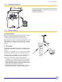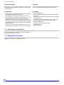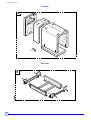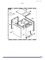
1
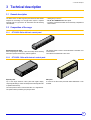
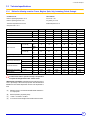
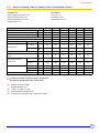
EN Fuel oil/gas-fired boilers GT 330 Installation and Service Manual 300007650-001-02 . Declaration of conformity CE The appliance complies with the standard model described in declaration of compliance 1. It is manufactured and distributed pursuant to the requirements of european directives. C002232-A The original of the declaration of compliance is available from the manufacturer. 2 GT 330 05/03/2013 - 300007650-001-02 . Contents 1 Introduction . . . . . . . . . . . . . . . . . . . . . . . . . . . . . . . . . . . . . . . . . . . . . . . . . . . . . . . . . . . . . . . . . . . . . . . . . . . . .5 1.1 1.2 Symbols and abbreviations . . . . . . . . . . . . . . . . . . . . . . . . . . . . . . . . . . . . . . . . . . . . . . . . . . . . . . . . . . . . . . . . . . . . . . . . . . . . . . . .5 General. . . . . . . . . . . . . . . . . . . . . . . . . . . . . . . . . . . . . . . . . . . . . . . . . . . . . . . . . . . . . . . . . . . . . . . . . . . . . . . . . . . . . . . . . . . . . . . .5 1.2.1 Manufacturer's liability . . . . . . . . . . . . . . . . . . . . . . . . . . . . . . . . . . . . . . . . . . . . . . . . . . . . . . . . . . . . . . . . . . . . . . . . . . . . . .5 1.2.2 Installer's liability . . . . . . . . . . . . . . . . . . . . . . . . . . . . . . . . . . . . . . . . . . . . . . . . . . . . . . . . . . . . . . . . . . . . . . . . . . . . . . . . . .5 1.2.3 User's liability . . . . . . . . . . . . . . . . . . . . . . . . . . . . . . . . . . . . . . . . . . . . . . . . . . . . . . . . . . . . . . . . . . . . . . . . . . . . . . . . . . . . .5 1.3 Homologations . . . . . . . . . . . . . . . . . . . . . . . . . . . . . . . . . . . . . . . . . . . . . . . . . . . . . . . . . . . . . . . . . . . . . . . . . . . . . . . . . . . . . . . . . .6 1.3.1 Certifications . . . . . . . . . . . . . . . . . . . . . . . . . . . . . . . . . . . . . . . . . . . . . . . . . . . . . . . . . . . . . . . . . . . . . . . . . . . . . . . . . . . . .6 1.3.2 Directive 97/23/EC . . . . . . . . . . . . . . . . . . . . . . . . . . . . . . . . . . . . . . . . . . . . . . . . . . . . . . . . . . . . . . . . . . . . . . . . . . . . . . . . .6 2 Safety instructions and recommendations. . . . . . . . . . . . . . . . . . . . . . . . . . . . . . . . . . . . . . . . . . . . . . . . . . . .7 2.1 Safety instructions . . . . . . . . . . . . . . . . . . . . . . . . . . . . . . . . . . . . . . . . . . . . . . . . . . . . . . . . . . . . . . . . . . . . . . . . . . . . . . . . . . . . . . .7 2.1.1 Fire hazard . . . . . . . . . . . . . . . . . . . . . . . . . . . . . . . . . . . . . . . . . . . . . . . . . . . . . . . . . . . . . . . . . . . . . . . . . . . . . . . . . . . . . . .7 2.1.2 Risk of intoxication . . . . . . . . . . . . . . . . . . . . . . . . . . . . . . . . . . . . . . . . . . . . . . . . . . . . . . . . . . . . . . . . . . . . . . . . . . . . . . . . .7 2.1.3 Risk of being burnt . . . . . . . . . . . . . . . . . . . . . . . . . . . . . . . . . . . . . . . . . . . . . . . . . . . . . . . . . . . . . . . . . . . . . . . . . . . . . . . . .7 2.1.4 Risk of damage . . . . . . . . . . . . . . . . . . . . . . . . . . . . . . . . . . . . . . . . . . . . . . . . . . . . . . . . . . . . . . . . . . . . . . . . . . . . . . . . . . .7 2.2 Recommendations . . . . . . . . . . . . . . . . . . . . . . . . . . . . . . . . . . . . . . . . . . . . . . . . . . . . . . . . . . . . . . . . . . . . . . . . . . . . . . . . . . . . . . .8 3 Technical description . . . . . . . . . . . . . . . . . . . . . . . . . . . . . . . . . . . . . . . . . . . . . . . . . . . . . . . . . . . . . . . . . . . . .9 3.1 3.2 General description . . . . . . . . . . . . . . . . . . . . . . . . . . . . . . . . . . . . . . . . . . . . . . . . . . . . . . . . . . . . . . . . . . . . . . . . . . . . . . . . . . . . . .9 Composition of the range . . . . . . . . . . . . . . . . . . . . . . . . . . . . . . . . . . . . . . . . . . . . . . . . . . . . . . . . . . . . . . . . . . . . . . . . . . . . . . . . . .9 3.2.1 GT 330 S3: Boiler with basic control panel . . . . . . . . . . . . . . . . . . . . . . . . . . . . . . . . . . . . . . . . . . . . . . . . . . . . . . . . . . . . . .9 3.2.2 GT 330 B3 : Boiler with electronic control panel. . . . . . . . . . . . . . . . . . . . . . . . . . . . . . . . . . . . . . . . . . . . . . . . . . . . . . . . . . .9 3.2.3 GT 330 DIEMATIC-m3: Boiler with DIEMATIC-m3 electronic control panel . . . . . . . . . . . . . . . . . . . . . . . . . . . . . . . . . . . .10 3.2.4 GT 330 K3: Boiler with K3 control panel . . . . . . . . . . . . . . . . . . . . . . . . . . . . . . . . . . . . . . . . . . . . . . . . . . . . . . . . . . . . . . .10 3.3 Technical specifications . . . . . . . . . . . . . . . . . . . . . . . . . . . . . . . . . . . . . . . . . . . . . . . . . . . . . . . . . . . . . . . . . . . . . . . . . . . . . . . . . .11 3.3.1 Boilers for following countries: France, Belgium, Spain, Italy, Luxemburg, Poland, Portugal . . . . . . . . . . . . . . . . . . . . . . .11 3.3.2 Boilers for Switzerland . . . . . . . . . . . . . . . . . . . . . . . . . . . . . . . . . . . . . . . . . . . . . . . . . . . . . . . . . . . . . . . . . . . . . . . . . . . . .12 3.3.3 Boilers for following countries: Germany, Austria, Czech Republic, Slovenia . . . . . . . . . . . . . . . . . . . . . . . . . . . . . . . . . . .13 3.3.4 Boilers for following countries: Algeria, Bulgaria, China, Finland, Greece, Ireland, Jordan, Lebanon, Morocco, Norway, Romania, Russia, Syria, Tunisia, Turkey14 4 Installation . . . . . . . . . . . . . . . . . . . . . . . . . . . . . . . . . . . . . . . . . . . . . . . . . . . . . . . . . . . . . . . . . . . . . . . . . . . . .15 4.1 Regulations governing installation . . . . . . . . . . . . . . . . . . . . . . . . . . . . . . . . . . . . . . . . . . . . . . . . . . . . . . . . . . . . . . . . . . . . . . . . . .15 4.1.1 In general . . . . . . . . . . . . . . . . . . . . . . . . . . . . . . . . . . . . . . . . . . . . . . . . . . . . . . . . . . . . . . . . . . . . . . . . . . . . . . . . . . . . . . .15 4.1.2 In particular for France: . . . . . . . . . . . . . . . . . . . . . . . . . . . . . . . . . . . . . . . . . . . . . . . . . . . . . . . . . . . . . . . . . . . . . . . . . . . .15 4.1.3 In particular for Germany . . . . . . . . . . . . . . . . . . . . . . . . . . . . . . . . . . . . . . . . . . . . . . . . . . . . . . . . . . . . . . . . . . . . . . . . . . .16 4.2 Package list . . . . . . . . . . . . . . . . . . . . . . . . . . . . . . . . . . . . . . . . . . . . . . . . . . . . . . . . . . . . . . . . . . . . . . . . . . . . . . . . . . . . . . . . . . .16 4.3 Choice of the location . . . . . . . . . . . . . . . . . . . . . . . . . . . . . . . . . . . . . . . . . . . . . . . . . . . . . . . . . . . . . . . . . . . . . . . . . . . . . . . . . . . .17 4.3.1 Main dimensions . . . . . . . . . . . . . . . . . . . . . . . . . . . . . . . . . . . . . . . . . . . . . . . . . . . . . . . . . . . . . . . . . . . . . . . . . . . . . . . . .17 4.3.2 Position of the boiler. . . . . . . . . . . . . . . . . . . . . . . . . . . . . . . . . . . . . . . . . . . . . . . . . . . . . . . . . . . . . . . . . . . . . . . . . . . . . . .18 4.3.3 Ventilation . . . . . . . . . . . . . . . . . . . . . . . . . . . . . . . . . . . . . . . . . . . . . . . . . . . . . . . . . . . . . . . . . . . . . . . . . . . . . . . . . . . . . .19 4.4 Example of an installation. . . . . . . . . . . . . . . . . . . . . . . . . . . . . . . . . . . . . . . . . . . . . . . . . . . . . . . . . . . . . . . . . . . . . . . . . . . . . . . . .20 4.5 Hydraulic connections . . . . . . . . . . . . . . . . . . . . . . . . . . . . . . . . . . . . . . . . . . . . . . . . . . . . . . . . . . . . . . . . . . . . . . . . . . . . . . . . . . .21 4.5.1 Flushing the system . . . . . . . . . . . . . . . . . . . . . . . . . . . . . . . . . . . . . . . . . . . . . . . . . . . . . . . . . . . . . . . . . . . . . . . . . . . . . . .21 4.5.2 Sludge removal . . . . . . . . . . . . . . . . . . . . . . . . . . . . . . . . . . . . . . . . . . . . . . . . . . . . . . . . . . . . . . . . . . . . . . . . . . . . . . . . . .21 4.5.3 Hydraulic connection of the heating circuit. . . . . . . . . . . . . . . . . . . . . . . . . . . . . . . . . . . . . . . . . . . . . . . . . . . . . . . . . . . . . .21 4.5.4 Safety valve . . . . . . . . . . . . . . . . . . . . . . . . . . . . . . . . . . . . . . . . . . . . . . . . . . . . . . . . . . . . . . . . . . . . . . . . . . . . . . . . . . . . .22 4.5.5 Connection of the water circuit for domestic use . . . . . . . . . . . . . . . . . . . . . . . . . . . . . . . . . . . . . . . . . . . . . . . . . . . . . . . . .22 4.6 Chimney connection . . . . . . . . . . . . . . . . . . . . . . . . . . . . . . . . . . . . . . . . . . . . . . . . . . . . . . . . . . . . . . . . . . . . . . . . . . . . . . . . . . . . .23 4.6.1 Flue size. . . . . . . . . . . . . . . . . . . . . . . . . . . . . . . . . . . . . . . . . . . . . . . . . . . . . . . . . . . . . . . . . . . . . . . . . . . . . . . . . . . . . . . .23 4.6.2 Connection to the flue gas pipe . . . . . . . . . . . . . . . . . . . . . . . . . . . . . . . . . . . . . . . . . . . . . . . . . . . . . . . . . . . . . . . . . . . . . .23 4.7 Fuel-oil or gas connections. . . . . . . . . . . . . . . . . . . . . . . . . . . . . . . . . . . . . . . . . . . . . . . . . . . . . . . . . . . . . . . . . . . . . . . . . . . . . . . .24 4.8 Electrical connections. . . . . . . . . . . . . . . . . . . . . . . . . . . . . . . . . . . . . . . . . . . . . . . . . . . . . . . . . . . . . . . . . . . . . . . . . . . . . . . . . . . .24 4.9 Filling the system . . . . . . . . . . . . . . . . . . . . . . . . . . . . . . . . . . . . . . . . . . . . . . . . . . . . . . . . . . . . . . . . . . . . . . . . . . . . . . . . . . . . . . .24 05/03/2013 - 300007650-001-02 GT 330 3 . 5 Commissioning . . . . . . . . . . . . . . . . . . . . . . . . . . . . . . . . . . . . . . . . . . . . . . . . . . . . . . . . . . . . . . . . . . . . . . . . .25 6 Switching off the boiler. . . . . . . . . . . . . . . . . . . . . . . . . . . . . . . . . . . . . . . . . . . . . . . . . . . . . . . . . . . . . . . . . . .25 6.1 6.2 7 Precautions required in the case of long boiler stops. . . . . . . . . . . . . . . . . . . . . . . . . . . . . . . . . . . . . . . . . . . . . . . . . . . . . . . . . . . .25 Precautions required if the heating is stopped when there is a risk of freezing . . . . . . . . . . . . . . . . . . . . . . . . . . . . . . . . . . . . . . . .25 Checking and maintenance . . . . . . . . . . . . . . . . . . . . . . . . . . . . . . . . . . . . . . . . . . . . . . . . . . . . . . . . . . . . . . .26 7.1 System maintenance . . . . . . . . . . . . . . . . . . . . . . . . . . . . . . . . . . . . . . . . . . . . . . . . . . . . . . . . . . . . . . . . . . . . . . . . . . . . . . . . . . . .26 7.1.1 Water level . . . . . . . . . . . . . . . . . . . . . . . . . . . . . . . . . . . . . . . . . . . . . . . . . . . . . . . . . . . . . . . . . . . . . . . . . . . . . . . . . . . . . .26 7.1.2 Draining . . . . . . . . . . . . . . . . . . . . . . . . . . . . . . . . . . . . . . . . . . . . . . . . . . . . . . . . . . . . . . . . . . . . . . . . . . . . . . . . . . . . . . . .26 7.2 Data plate . . . . . . . . . . . . . . . . . . . . . . . . . . . . . . . . . . . . . . . . . . . . . . . . . . . . . . . . . . . . . . . . . . . . . . . . . . . . . . . . . . . . . . . . . . . . .26 7.3 Maintenance . . . . . . . . . . . . . . . . . . . . . . . . . . . . . . . . . . . . . . . . . . . . . . . . . . . . . . . . . . . . . . . . . . . . . . . . . . . . . . . . . . . . . . . . . . .27 7.3.1 Cleaning the flue gas circuit . . . . . . . . . . . . . . . . . . . . . . . . . . . . . . . . . . . . . . . . . . . . . . . . . . . . . . . . . . . . . . . . . . . . . . . . .27 7.3.2 Cleaning the combustion chamber. . . . . . . . . . . . . . . . . . . . . . . . . . . . . . . . . . . . . . . . . . . . . . . . . . . . . . . . . . . . . . . . . . . .27 7.3.3 Positioning of the baffle plates . . . . . . . . . . . . . . . . . . . . . . . . . . . . . . . . . . . . . . . . . . . . . . . . . . . . . . . . . . . . . . . . . . . . . . .28 7.3.4 Cleaning the flue gas box. . . . . . . . . . . . . . . . . . . . . . . . . . . . . . . . . . . . . . . . . . . . . . . . . . . . . . . . . . . . . . . . . . . . . . . . . . .29 7.3.5 Chemical sweeping . . . . . . . . . . . . . . . . . . . . . . . . . . . . . . . . . . . . . . . . . . . . . . . . . . . . . . . . . . . . . . . . . . . . . . . . . . . . . . .29 7.5 Maintenance of the burner . . . . . . . . . . . . . . . . . . . . . . . . . . . . . . . . . . . . . . . . . . . . . . . . . . . . . . . . . . . . . . . . . . . . . . . . . . . . . . . .30 8 4 Spare parts - GT 330 . . . . . . . . . . . . . . . . . . . . . . . . . . . . . . . . . . . . . . . . . . . . . . . . . . . . . . . . . . . . . . . . . . . . .31 GT 330 05/03/2013 - 300007650-001-02 1. Introduction 1 Introduction 1.1 Symbols and abbreviations Caution danger Reference Risk ZRefer of injury and damage to equipment. Attention must be to another manual or other pages in this instruction paid to the warnings on safety of persons and equipment. manual. DHW: Domestic hot water Specific information Information must be kept in mind to maintain comfort. 1.2 General 1.2.1 Manufacturer's liability Our products are manufactured in compliance with the requirements of the various applicable European Directives. They are therefore delivered with 1 marking and all relevant documentation. Our liability as the manufacturer may not be invoked in the following cases: ` Failure to abide by the instructions on using the appliance. ` Faulty or insufficient maintenance of the appliance. ` Failure to abide by the instructions on installing the appliance. The installer is responsible for the installation and inital start up of the appliance. The installer must respect the following instructions: ` Carry out installation in compliance with the prevailing legislation and standards. Read and follow the instructions given in the manuals provided with the appliance. ` Perform the initial start up and carry out any checks necessary. ` Explain the installation to the user. ` If a maintenance is necessary, warn the user of the obligation to check the appliance and maintain it in good working order. ` Give all the instruction manuals to the user. In the interest of customers, we are continuously endeavouring to make improvements in product quality. All the specifications stated in this document are therefore subject to change without notice. 1.2.2 ` 1.2.3 Installer's liability User's liability To ensure the optimum operation of your appliance, we strongly recommend that you abide by the following instructions: ` Read and follow the instructions given in the manuals provided with the appliance. ` Call on qualified professionals to carry out installation and initial start up. ` Get your installer to explain your installation to you. ` Have the required checks and services done. ` Keep the instruction manuals in good condition close to the appliance. This appliance is not intended to be used by persons (including children) whose physcial, sensory or mental capacity is impaired or persons with no experience or knowledge, unless they have the benefit, through the intermediary of a person responsible for their safety, of supervision or prior instructions regarding use of the appliance. Care should be taken to ensure that children do not play with the appliance. 05/03/2013 - 300007650-001-02 GT 330 5 1. Introduction 1.3 Homologations 1.3.1 Certifications In general CE identification no: 1312 BR 46 17 (Base): France, Germany, Austria, Belgium, Spain, Italy, Luxemburg, Poland, Portugal, Czech Republic, Slovenia, Switzerland. CE identification no: 1312 BR 47 83 (Export): Algeria, Bulgaria, China, Finland, Greece, Ireland, Jordan, Lebanon, Morocco, Norway, Romania, Russia, Syria, Tunisia, Turkey. In particular for Switzerland: Accreditation no. OFEFP: 293010 Accreditation no. AEAI: 8088 1.3.2 Directive 97/23/EC Gas and oil boilers with a maximum operating temperature of 110°C and hot water tanks with a maximum operating pressure of 10 bar pertain to article 3.3 of the directive, and therefore, cannot be CEmarked to certify compliance with the directive 97/23 EC. The boilers and hot water tanks are designed and manufactured in accordance with the sound engineering practice, as requested in article 3.3 of the directive 97/23/EC, it is certified by compliance with the directives 90/396/EC, 92/42/EC, 2006/95/EC and 2004/108/EC. 6 GT 330 05/03/2013 - 300007650-001-02 2. Safety instructions and recommendations 2 Safety instructions and recommendations 2.1 Safety instructions For a proper operating of the boiler, follow carefully the Before any work, switch off the mains supply to the instructions. appliance. Only qualified professionals are authorised to work on the Keep to the polarity shown on the terminals: phase (L), appliance neutral and the installation. (N) and earth . 4 Incorrect use or unauthorised modifications to the installation or the equipment itself invalidate any right to claim. 2.1.1 Fire hazard to store inflammable products and materials inIt istheforbidden boiler room or close to the boiler, even temporarily. If you smell gas, do not use a naked flame, do not smoke, do not operate electrical contacts or switches (doorbell, lights, motor, lift, etc.): 2.1.2 1. Switch the appliance off. 2. Open the windows. 3. Evacuate the premises. 4. Contact a qualified professional. Risk of being burnt Depending on the settings of the appliance: - The temperature of the radiators may reach 95°C. - The temperature of the flue gas conduits may exceed 60°C. 2.1.4 1.Shut off the gas supply. 2.Open the windows. 3.Extinguish all flames. 4.Evacuate the premises. 5.Contact a qualified professional. 6.Inform the gas supplier. Risk of intoxication Do not obstruct the air inlets in the room (even partially). If you smell flue gases: 2.1.3 Keep children away from the boiler. - The temperature of the domestic hot water may reach 65°C. Risk of damage Do not stock chloride or fluoride compounds close to the appliance. Install the appliance in frost-free premises. Do not neglect to service the appliance: Contact a qualified professional or take out a maintenance contract for the annual servicing of the appliance. 05/03/2013 - 300007650-001-02 GT 330 7 2. Safety instructions and recommendations 2.2 Recommendations ` Check regularly that the installation contains water and is pressurised. ` Keep the appliance accessible at all times. ` Avoid draining the installation. ` The appliance should be on Summer or Antrifreeze mode rather than switched off to guarantee the following functions: ` Anti blocking of pumps. ` Antifreeze protection. ` Protection against corrosion on domestic hot water tanks fitted with a titanium anode. 8 GT 330 05/03/2013 - 300007650-001-02 3. Technical description 3 Technical description 3.1 General description The boilers of the GT 330 range are pressurised hot water boilers designed for connecting to a flue pipe which require a separate automatic fuel-oil or gas burner. GT 330 boilers have the following characteristics: - Heating body in cast iron. - S3, B3, K3 or DIEMATIC-m3 control panel. - Production of domestic hot water can be ensured by a separate hot water calorifier. 3.2 Composition of the range 3.2.1 GT 330 S3: Boiler with basic control panel Standard panel to be fitted Panel comprising the settings, control and safety devices allowing the boiler to operate autonomously, without regulation. 3.2.2 The standard panel is used to connect the boiler to the boiler room control cabinet. This cabinet can be fitted with control units. GT 330 B3 : Boiler with electronic control panel. Separate panel Side panel Top of the range electronic control panel with digital display, comprising the settings, control and safety devices allowing the boiler to operate autonomously. A version of the B3 control panel with lateral attachment is also available. The control panel is used to control boilers with 1 or 2-stage burners. This panel makes it possible to give priority to DHW. 05/03/2013 - 300007650-001-02 GT 330 9 3. Technical description 3.2.3 GT 330 DIEMATIC-m3: Boiler with DIEMATIC-m3 electronic control panel Separate panel Top of the range electronic control panel with digital display, comprising the settings, control and safety devices allowing the boiler to operate autonomously. The DIEMATIC-m3 panel is fitted as standard with a control unit which operates according to the outside temperature. Side panel A version of the DIEMATIC-m3 control panel with lateral attachment is also available. The control panel enables the operation of a boiler fitted with a 1 stage, 2 stage or modulating burner. The DIEMATIC-m3 panel also allows the boiler to be used as a master boiler for installations with 2 to 10 boilers in cascade. The other boilers (1 to 9) must be fitted with a "K3" control panel. 3.2.4 GT 330 K3: Boiler with K3 control panel Separate panel The K3 control panel is fitted only in association with a boiler fitted with a DIEMATIC-m3 control panel as part of a cascade installation (2 to 10 boilers can be connected in a cascade). Side panel A version of the K3 control panel with lateral attachment is also available. The control panel enables the operation of a boiler fitted with a 1 stage, 2 stage or modulating burner. 10 GT 330 05/03/2013 - 300007650-001-02 3. Technical description 3.3 Technical specifications 3.3.1 Boilers for following countries: France, Belgium, Spain, Italy, Luxemburg, Poland, Portugal Conditions of use: Test conditions: Maximum operating temperature: 100 °C CO² Fuel oil = 13% Maximum operating pressure: 6 bar CO² Natural gas = 9.5% Thermostat adjustable from 30 to 90°C Ambient temperature: 20 °C Safety thermostat: 110 °C GT 334 GT 335 GT 336 GT 337 GT 338 GT 339 Useful output Boiler kW 55-90 90-115 115-150 150-185 185-230 230-280 Power input kW 60-99 97-126 124-164 162-202 200-251 248-304 Water content l 96 116 136 156 176 196 4 5 6 7 8 9 % 0.150 0.135 0.125 0.115 0.100 0.085 Number of sections Stand-by losses - 50 °C (A) Number of baffle plates Water resistance 6 10 10 10 12 12 ∆ T = 10K (B) mbar (C) 11 18 31 46 68 105 ∆ T = 15K (B) mbar (C) 4.6 7.4 14.2 19.5 30.1 46 ∆ T = 20K (B) mbar (C) 2.6 4.2 8 11 17 26 < 200 < 190 < 190 < 190 < 190 < 190 0.2 0.4 0.7 1.2 1.8 2.2 Flue gas temperature (B) °C Pressure in the furnace for nozzle pressure = 0 (B) mbar (D) (C) Fuel oil Kg/h 151 192 252 309 383 465 Natural gas Kg/h 159 211 277 340 422 512 Inscribed diameter mm 377 377 377 377 377 377 Length mm 571 731 891 1051 1211 1371 Volume m3 0.096 0.122 0.148 0.174 0.200 0.226 Maintenance consumption* ∆ T = 30K % 0.150 0.135 0.125 0.115 0.100 0.085 Weight (empty) kg 612 736 846 981 1103 1230 Mass flue gas flow rate (B) Combustion chamber order for the boiler to operate correctly, it is imperative toIn respect the draught at the nozzle: 0 at the nozzle. *Maintenance consumption: total heat emission when the burner is off as a percentage of the nominal input power when the difference between the mean boiler temperature and the room temperature is 30 K. (A) Stand-by losses in accordance with NFD 30002 standard in % of input power. (B) Nominal operation (top boiler power). (C) 1 mbar = 10 mmWG = 10 daPa. (D) In no event must the draught at the nozzle exceed 0.2 mbar. 05/03/2013 - 300007650-001-02 GT 330 11 3. Technical description 3.3.2 Boilers for Switzerland Conditions of use: Test conditions: Maximum operating temperature: 100 °C CO² Fuel oil = 13% Maximum operating pressure: 6 bar CO² Natural gas = 9.5% Thermostat adjustable from 30 to 90°C Ambient temperature: 20 °C Safety thermostat: 110 °C Boiler GT 334 GT 335 GT 336 GT 337 GT 338 GT 339 kW 51-70 66-103 95-135 117-184 151-234 162-278 Power input kW 55-76 71-112 102-147 126-200 162-255 173-303 Water content l 96 116 136 156 176 196 4 5 6 7 8 9 % 0.150 0.135 0.125 0.115 0.100 0.085 Useful output Number of sections Stand-by losses - 50 °C (A) Number of baffle plates Water resistance 6 10 10 10 12 12 ∆ T = 10K (B) mbar (C) 10 17 29 44 68 105 ∆ T = 15K (B) mbar (C) 5 7 13 20 30 46 ∆ T = 20K (B) mbar (C) 3 4 7 11 17 26 < 180 < 180 < 180 < 180 < 180 < 180 Flue gas temperature (C) °C Pressure in the furnace for nozzle pressure = 0 (B) (D) mbar (C) 0.2 0.4 0.7 1.2 1.8 2.2 Fuel oil Kg/h 116 171 225 306 390 463 Natural gas Kg/h 122 180 236 321 409 486 Inscribed diameter mm 377 377 377 377 377 377 Length mm 571 731 891 1051 1211 1371 Volume m3 0.096 0.122 0.148 0.174 0.200 0.226 ∆ T = 30K % 0.150 0.135 0.125 0.115 0.100 0.085 kg 612 736 846 981 1103 1230 Mass flue gas flow rate (B) DIN 4705 Teil 1 Combustion chamber Maintenance consumption* Weight (empty) order for the boiler to operate correctly, it is imperative toIn respect the draught at the nozzle: 0 at the nozzle. (A) Standby consumption LVR 92 (Boiler temperature: 70 °C) (B) Nominal operation (top boiler power). (C) 1 mbar = 10 mmWG = 10 daPa. (D) In no event must the draught at the nozzle exceed 0.2 mbar. 12 GT 330 05/03/2013 - 300007650-001-02 3. Technical description 3.3.3 Boilers for following countries: Germany, Austria, Czech Republic, Slovenia Conditions of use: Test conditions: Maximum operating temperature: 100 °C CO² Fuel oil = 13% Maximum operating pressure: 6 bar CO² Natural gas = 9.5% Thermostat adjustable from 30 to 90°C Ambient temperature: 20 °C Safety thermostat: 110 °C Boiler GT 334 GT 335 GT 336 GT 337 GT 338 GT 339 kW 55-80 80-110 110-140 140-175 175-210 210-250 Power input kW 60-87 86-120 119-153 151-190 188-228 226-271 Water content l 96 116 136 156 176 196 Useful output Number of sections 4 5 6 7 8 9 Number of baffle plates 6 10 10 10 12 12 Maintenance consumption (A) ∆ T = 30K % 0.150 0.135 0.125 0.115 0.100 0.085 ∆ T = 10K (C) mbar (B) 8.7 16.5 27 41.2 56.9 84 ∆ T = 20K (C) mbar (B) 2.1 3.8 7 9.6 14.2 20.8 Water resistance Flue gas temperature (C) °C < 180 < 180 < 180 < 180 < 180 < 180 Pressure in the furnace for nozzle pressure = 0 (C) (D) Pa (B) 20 35 60 110 150 200 Mass flue gas flow rate (C) DIN 4705 Teil 1 Combustion chamber Fuel oil kg per sec 0.037 0.051 0.065 0.081 0.097 0.115 Natural gas kg per sec 0.039 0.054 0.068 0.085 0.102 0.121 Inscribed diameter mm 377 377 377 377 377 377 Length mm 571 731 891 1051 1211 1371 Volume m3 0.096 0.122 0.148 0.174 0.200 0.226 kg 612 736 846 981 1103 1230 Weight (empty) order for the boiler to operate correctly, it is imperative toIn respect the draught at the nozzle: 0 at the nozzle. (A) Standby consumption LVR 92 (Boiler temperature: 70 °C) (B) 1 mbar = 10 mmWG = 10 daPa. (C) Nominal operation (top boiler power). (D) In no event must the draught at the nozzle exceed 0.2 mbar. 05/03/2013 - 300007650-001-02 GT 330 13 3. Technical description 3.3.4 Boilers for following countries: Algeria, Bulgaria, China, Finland, Greece, Ireland, Jordan, Lebanon, Morocco, Norway, Romania, Russia, Syria, Tunisia, Turkey Conditions of use: Test conditions: Maximum operating temperature: 100 °C CO² Fuel oil = 13% Maximum operating pressure: 6 bar CO² Natural gas = 9.5% Thermostat adjustable from 30 to 90°C Ambient temperature: 20 °C Safety thermostat: 110 °C Boiler GT 334 GT 335 GT 336 GT 337 GT 338 GT 339 Useful output kW 70-105 105-140 140-180 180-230 230-280 280-330 Power input kW 76-117 115-156 153-199 197-253 252-309 305-361 Water content l 96 116 136 156 176 196 4 5 6 7 8 9 0.17 0.14 0.13 0.11 0.10 0.09 6 10 10 6 6 6 mbar (B) 6.2 10.9 20.4 30 44.5 63.8 Flue gas temperature (C) °C 210 210 210 210 210 210 Pressure in the furnace for nozzle pressure = 0 (C) (D) mbar (B) 0.3 0.6 1.1 1.6 2.2 2.5 Mass flue gas flow rate (C) Fuel oil Kg/h 178 238 306 391 475 560 Natural gas Kg/h 187 250 321 410 499 588 m3 0.163 0.206 0.249 0.292 0.335 0.378 Inscribed diameter mm 377 377 377 377 377 377 Length mm 571 731 891 1051 1211 1371 Volume m3 0.096 0.122 0.148 0.174 0.200 0.226 kg 612 736 846 981 1103 1230 Number of sections Stand-by losses - 50 °C (A) % Number of baffle plates Water resistance ∆ T = 15K Flue gas circuit volume (Flue ways + Combustion chamber) Combustion chamber Weight (empty) order for the boiler to operate correctly, it is imperative toIn respect the draught at the nozzle: 0 at the nozzle. (A) Stand-by losses in accordance with prevailing standard (B) 1 mbar = 10 mmWG = 10 daPa (C) Nominal operation (top boiler power) (D) In no event must the draught at the nozzle exceed 0.2 mbar. 14 GT 330 05/03/2013 - 300007650-001-02 4. Installation 4 Installation 4.1 Regulations governing installation 4.1.1 In general Installation must be carried out in accordance with the prevailing regulations, the codes of practice and the recommendations in these instructions. 4.1.2 In particular for France: Establishments open to the public Heating installations must be designed and constructed in such a way as to prevent the return of water from the heating circuit and products put into it into the drinking water network located upstream. The installation must not be in direct relation with the drinking water network (Article 16-7 of the departmental health Directive). Statutory terms and conditions of installation: When these installations are fitted with a filling system connected to the drinking water network, they comprise a CB disconnector (disconnector for zones with non-controllable pressure differences) which satisfy the functional requirements of the NF P 43-011 standard. - Safety regulations against fire and panic in establishments open to the public: The installation and maintenance of the appliance must be carried out in compliance with the statutory texts and rules of the codes of conduct in force, particularly: a. General regulations For all appliances: Residential buildings Statutory terms and conditions of installation and maintenance: - Articles GZ - Installations operating on combustible gases and liquefied hydrocarbons. The installation and maintenance of the appliance must be carried out by a qualified professional in compliance with the statutory texts of the codes of conduct in force, particularly: Then, depending on use: - Order of 27 April 2009 amending the Order of 2 August 1977 Technical and safety rules applicable to combustible gas and liquefied hydrocarbon installations situated inside residential buildings and their annexes. b. Instructions specific to each type of establishment open to the public (hospitals, stores, etc.). - NF P 45-204 standards Gas installation, (formerly DTU 61-1, gas installations: April 1982, addendum no 1: July 1984). - Local Sanitary Regulations For appliances connected to the electricity network: - NF C 15-100 standards Low voltage electrical installation - Rules.. 05/03/2013 - 300007650-001-02 - Articles CH-Heating, ventilation, refrigeration, air conditioning and production of steam and domestic hot water. Certificate of compliance (only concerns GT 330 boilers fitted with a gas burner) In application of Article 25 of the Order of 27 April 2009 amending the Order of 2 August 1977 amended and Article 1 of the amended Order of 05/02/1999, the installer is required to draw up certificates of conformity approved by the Ministers responsible for construction and gas safety: - Different forms (forms 1, 2 or 3) for a new gas installation. - Model 4 in particular after replacing a furnace with a new one. GT 330 15 4. Installation 4.1.3 In particular for Germany Abide by the following standards, rules and directives when installing and commissioning the boiler: - DIN 4705: calculation of chimney dimensions. - DIN EN 12828 (June 2003 edition): heating systems in buildings. Planning of hot water heating installations (up to a maximum operating temperature of 105°C and a maximum output of 1 MW). - DIN 4753: drinking and industrial water heating installations. - DIN 1988: technical rules on drinking water installations (TRW). - DVGW-TRGI: technical rules on gas installations, including complementary equipment. - Working paper DVGW G 260/I: technical rules on the nature of the gas. 4.2 Package list ZSee assembly instructions. 16 GT 330 05/03/2013 - 300007650-001-02 4. Installation 4.3 Choice of the location 4.3.1 Main dimensions (2) 325 718 (1) Sludge removal hole Ø Rp 2 1/2 (plugged) Rp 1 1/2 socket for the safety control unit Heating flow (Flange + Counter flange with collar to be welded) orifice Ø 2" 1/2 (Option: Ø 2") Heating return (Flange + Counter flange with collar to be welded) orifice Ø 2" 1/2 (Option: Ø 2") Rp 1 1/2 draining outlet (plugged) Standard panel Table K3 + DIEMATIC-m3 + B3 160 (1) Boiler 50 Mk Tapped connection (1) Adjustable feet: Basic dimension 0 mm, adjustment possible: 0 to 40 mm (2) The lateral control panel can be mounted to the right or left of the boiler. Exact height positioning defined by the fitter during assembly. GT... GT 334 GT 335 GT 336 GT 337 GT 338 GT 339 A 130 130 130 130 130 130 B 105 105 105 105 105 105 C 165 165 165 165 165 165 D 738 738 738 738 738 738 H 1297 1297 1297 1297 1297 1297 A 355 355 355 355 355 355 B 195 195 195 195 195 195 C 145 145 145 145 145 145 D 755 755 755 755 755 755 H 1387 1387 1387 1387 1387 1387 L (mm) 991 1151 1311 1471 1631 1791 P (mm) 490 650 810 970 1130 1290 R (mm) 180 180 180 200 200 200 05/03/2013 - 300007650-001-02 GT 330 17 4. Installation 4.3.2 Position of the boiler For the assembly and because of their design, GT 330 boilers require no special base. Their closed furnace system means that the floor need not have refractory properties. All you have to ensure is that the floor can support the weight of the boiler when it is fitted for operation. The dimensions (in mm) correspond to the minimum recommended dimensions needed to ensure adequate accessibility around the boiler. If the boiler location is not determined precisely, leave enough space around the boiler to facilitate monitoring and maintenance operations. 0,1 5m B M000530 1,1 9m 1m 0,5 m A 0,8 0,5 m m 1,5 m Boiler Size A B GT 334 GT 335 GT 336 GT 337 GT 338 GT 339 mm 840 1000 1160 1320 1480 1640 Standard panel mm 105 105 105 105 105 105 K3 control panel B3 DIEMATIC-m3 mm 195 195 195 195 195 195 Pay attention to the overall volume of the burner when the door is open. To install several boilers in cascade, these dimensions should be adapted accordingly. 18 GT 330 05/03/2013 - 300007650-001-02 4. Installation 4.3.3 Ventilation To allow the input of combustive air, sufficient ventilation must be provided in the boiler room, for which the cross section and emplacement must satisfy regulations in force in the country in which the boiler is installed. These compounds are present, for example, in aerosol sprays, paints, solvents, cleaning products, washing products, detergents, glues, snow clearing salts, etc. Position the air inlets in relation to the high ventilation vents in order that the air is refreshed throughout the boiler room. • Therefore: Do not obstruct the air inlets in the room (even partially). In order to avoid damage to the boiler, it is necessary to prevent the contamination of combustion air by chlorine and/or fluoride compounds, which are particularly corrosive. • Do not pull in air evacuated from premises using such products: hairdressing salons, dry cleaners, industrial premises (solvents), premises containing refrigeration systems (risk of refrigerant leakage), etc. Do not stock such products close to the boilers. If the boiler and/or peripheral equipment are corroded by such chloride or fluoride compounds, the contractual guarantee cannot be applied. France The minimum cross sections and the emplacement of the fresh air inlet and the air discharge are governed by the order of 21/03/1968 amended by the orders of 26/02/1974 and 03/03/1976. ` Generator installed in a building for collective use (installations less than 70 kW) The fresh air inlet must: - Come out in the lower section of the premises, - Have a free minimum cross section calculated on the basis of 0.03 dm² per kilowatt installed output and at least equal to 2.5 dm². ` The air discharge must: - Be located in the upper section of the premises, - Rise above the roof (unless using an equivalent system which does not cause a nuisance to neighbours), - Have a free cross section (corresponding to 2/3 of that of the air inlet and at least equal to 2.5 dm²). Generator installed in a builing for individual use ` An adequate supply of fresh air must be provided as close as possible to the appliances. Its cross section must be at least 0.5 dm². ` In the upper section of the premises, an air outlet must ensure effective ventilation. Establishments open to the public ` New establishment: Refer to the order of 25/06/1980 (installations of more than 20 kW and less than or equal to 70 kW). ` Existing establishment: Refer to the order of 25/06/1980 (installations less than 70 kW). 05/03/2013 - 300007650-001-02 GT 330 19 4. Installation 4.4 Example of an installation The example of an installation shown below does not cover every possible configuration. Its sole aim is to draw your attention to the basic rules to be respected. GT 330 boiler with domestic hot water production using an independent tank 3 7 5 10 9 15 9 9 14 9 27 11 16 13 56 27 20 9 2 17 57 9 19 12 9 17 9 1 6 9 9 9 7 9 26 18 32 27 9 31 29 9 17 28 30 8219N008C 17 Drain cock 18 Heating circuit filling (with disconnector depending on prevailing regulations) 3-bar safety valve + Pressure gauge 19 Water treatment 5 Flow switch 20 Water meter 6 Air separator 26 DHW load pump 7 Automatic air vent 27 Non-return valve 9 Isolating valve 28 Domestic cold water inlet 10 3-way mixing valve 29 Pressure reducer (if mains pressure > 5.5 bar) 11 Boiler pump 30 Safety unit calibrated to 7 bar with indicator type discharge 12 Sludge decanting pot (particularly recommended on older installations) 31 Independent domestic hot water tanks 32 Domestic hot water loop pump (optional) 13 Flush valve 56 Domestic hot water circulation loop return 14 Water low safety pressure-sensitive switch 57 Domestic hot water outlet 15 Shunt pump 16 Expansion vessel 1 Heating flow 2 Heating return 3 20 GT 330 05/03/2013 - 300007650-001-02 4. Installation 4.5 Hydraulic connections 4.5.1 Flushing the system Installing the boiler in new installations (installations less than 6 months old) ` ` Clean the installation with a universal cleaner to eliminate debris from the appliance (copper, hemp, flux). ` Thoroughly flush the installation until the water runs clear and shows no impurities. 4.5.2 Sludge removal leads to the draining of large quantities of water, so remember to refill the system after the operation. Remove sludge from the installation. ZSee: Sludge removal. ` Flush the installation. ` Clean the installation with a universal cleaner to eliminate debris from the appliance (copper, hemp, flux). ` Thoroughly flush the installation until the water runs clear and shows no impurities. Sludge removal A tapped Rp 2" 1/2 hole with a plug has been provided on the bottom of the front of the boiler.. Fit a 1/4 turn valve (not supplied) on the opening to remove the sludge. 4.5.3 Installing the boiler in existing installations After this operation, go ahead and fill the installation. ZSee: Filling the system. never replace a boiler in an existing system without carefully rinsing the system first. Install a sludge decanting pot on the return pipe, very close to the boiler. Hydraulic connection of the heating circuit Water flow in the boiler The water flow in the boiler when the burner is operating must correspond with the following formulae: - Operation at modulated low temperature (minimum outlet temperature: 30°C); The burner can modulate down to 50% of the nominal stage. - Nominal water flow Qn = 0.86 Pn/20 - Minimum flow Qmin = 0.86 Pn/45 (this flow also corresponds with the minimum recycle flow in the boiler) - Maximum water flow Qmax = 0.86 Pn/5 Qn = flow in m3/h Pn = Nominal output (full boiler output) in kW. Operation in cascade After stopping the burner: - Timeout required before the order to close a 2 way valve: 3 min. - Switch a possible shunt pump (located between the boiler and a butterfly valve) off via the end of run contact of the butterfly valve. Operation with 2-stage burner - The water temperature in the boiler is maintained at 50°C or more; The first stage must be set to a minimum of 30% of the nominal stage. - Operation at modulated low temperature (minimum outlet temperature: 30°C); The first stage must be set to a minimum of 50% of the nominal stage. Operation with modulating burner - The water temperature in the boiler is maintained at 50°C or more: The burner can modulate down to 30% of the nominal stage. 05/03/2013 - 300007650-001-02 GT 330 21 4. Installation 4.5.4 Safety valve The safety valve must be connected to the boiler outlet and no other valve or flap must be interposed between it and the boiler. Minimum safety valve flowrate as a function of maximum boiler nominal output Minimum relieving capacity Maximum gross boiler output Unit (a) = kW Example Maximum boiler nominal output is 200 kW. Minimum safety valve flowrate must be 700 Kg/h. (b) = lb/h (c) = MBtu/h (d) = Kg/h 4.5.5 Connection of the water circuit for domestic use ZSee: Domestic hot water calorifier instructions. 22 GT 330 05/03/2013 - 300007650-001-02 4. Installation 4.6 Chimney connection The high-performance features of modern boilers and their use in specific conditions as a result of the advance in burner technology (e.g. first-stage or low modulation range operation) lead to very low flue gas temperatures (<160°C): The use of a draught moderator is recommended as well. - As a last resort (old, outside, badly insulated chimney), the baffle plates in the 4 upper flue ways can be partially removed, resulting in an insrease in the flue gas temperature. For this reason: - Use flue gas pipes designed to enable the flow of condensates which may result from such operating modes in order to prevent damage to the chimney. - Install a draining tee at the bottom of the chimney. 4.6.1 Flue size France: Refer to applicable regulations while determining the size of the flue. order for the boiler to operate correctly, it is imperative toIn respect the draught at the nozzle (= 0). Please note that GT 330 boilers have pressurised and tight furnaces and that the pressure at the connection to the chimney must not exceed 0 mbar, unless special sealing precautions have been taken, for instance in order to connect a static condenser/regenerator. 4.6.2 Connection to the flue gas pipe The connection shall be removable, and offer minimum load losses, i.e. it must be as short as possible with no sudden change in section. Its diameter shall always be at least equal to that of the boiler outlet, i.e.: - Ø 180 mm: for 4 to 6 sections - Ø 200 mm: for 7 to 9 sections Fit a measuring point (Ø 10 mm hole) on the flue, in order to adjust the burner (combustion check). 05/03/2013 - 300007650-001-02 GT 330 23 4. Installation 4.7 Fuel-oil or gas connections ZRefer to the instructions supplied with the burner. head deflector must be flush with the insulation ofThetheburner burner door. B O E F M001614-B A Furnace door insulation B Turbulator C 4 markings on Ø 170 D 4 markings on Ø 200 E 4 markings on Ø 220 F Pressure gauge measurement socket 4.8 Electrical connections Refer to the connection instructions supplied with the control Zpanel.. 4.9 Filling the system Filling shall be performed with a low flow rate from a low point in the boiler room in order to ensure that all the air in the boiler is bled from the high point of the system. VERY IMPORTANT: Instructions for starting up the boiler for the first time after the system is fully or partly drained: All the pumps must be stopped before filling (included shunt pump(s)). Do not add cold water suddenly into the boiler when it is hot. 24 GT 330 If all the air is not bled naturally to an expansion vessel which opens out onto the air, the system must include manual bleeder valves, in addition to automatic bleeder valves with the capability to bleed the system by themselves when it is operating, the manual bleeder valves are used to bleed all the high points of the system and to make sure that the filled system is free of air before the burner is turned on. 05/03/2013 - 300007650-001-02 5. Commissioning 5 Commissioning ZSee: - Control panel instructions - Burner instructions - Domestic hot water calorifier instructions 6 Switching off the boiler ` Set the On/Off switch to O. ZSee: Control panel instructions. ` DIEMATIC-m3 control panel The panel must always be supplied with 230V voltage: Cut the gas supply to the boiler (if present). - to ensure the anti-grip of the heating pump, - to ensure Titan Active System® operation when a titanium anode is protecting the DHW tank. Use the mode: - summer to shut down the heating. - antifreeze to shut down the boiler if you are to be absent. 6.1 Precautions required in the case of long boiler stops - The boiler and the chimney must be swept carefully. - Close all the doors of the boiler to prevent air from circulating inside the boiler. - We advise removing the pipe which connects the boiler to the chimney and to close off the nozzle with a cover. 6.2 Precautions required if the heating is stopped when there is a risk of freezing We recommend the use of a correctly dosed antifreeze agent to prevent to the heating circuit from freezing. If this cannot be done, drain the system completely. 05/03/2013 - 300007650-001-02 GT 330 25 7. Checking and maintenance 7 Checking and maintenance 7.1 System maintenance 7.1.1 Water level Regularly check the level of water in the system and top up if required, taking care that cold water is not added suddenly into the boiler when it is hot. This operation should be required only a few times in each heating season, with very low quantities of water; otherwise, look for the leak and repair it. The use of an automatic filling is strongly discouraged. 7.1.2 Draining We advise you against draining the system unless it is absolutely necessary. For example: Several months' absence with the risk of ice in the building. 7.2 Data plate Boiler type Manufacturing date Year of manufacture Week of manufacture Serial no. of the appliance M000534-B The rating plate fixed on the side of the boiler during installation is used to identify the boiler correctly and also provides the main specifications of the boiler. 26 GT 330 05/03/2013 - 300007650-001-02 7. Checking and maintenance 7.3 Maintenance The boiler will only operate efficiently if the exchange The operations described below shall only be performed surfaces with are kept clean. the boiler and power supply off. The boiler must be cleaned as often as necessary and, like the chimney, at least once a year or more in accordance with the prevailing regulations and the insurance contract taken out. 7.3.1 Cleaning the flue gas circuit - Unhook the front panel. - Open the cleaning door (top door) by unscrewing the 4 closing nuts (17 mm spanner). - Remove the baffle plates. - Carefully sweep the flue ways with the brush supplied for that purpose. - Also sweep the baffle plates and the front panel. - If possible, use a vacuum cleaner. - Replace the baffle plates. - Close the door. A 7.3.2 Cleaning the combustion chamber - Unscrew the 4 closing nuts and open the furnace door. - Brush out the inside of the furnace. - Use a vacuum cleaner to remove any soot which has accumulated in the combustion chamber. - Close the door and replace the front panel. A 05/03/2013 - 300007650-001-02 GT 330 27 7. Checking and maintenance 7.3.3 Positioning of the baffle plates The first two baffle plates in the 2 lower flue ways are fitted with stops allowing them to be positioned in the required emplacement. (1) Stop Boilers for following countries: France, Germany, Austria, Belgium, Spain, Italy, Luxemburg, Poland, Portugal, Slovenia, Czech Republic, Switzerland Baffles Upper Lower Flue ways GT 334 GT 335 GT 336 GT 337 GT 338 GT 339 Length: 410 mm A+B - 8 8 4 - - Length: 570 mm A+B 4 - - 4 8 8 Length : 412 mm C 2 2 2 2 4 2 Length: 572 mm C - - - - - 2 Boilers for following countries: Algeria, Bulgaria, China, Finland, Greece, Ireland, Jordan, Lebanon, Morocco, Norway, Romania, Russia, Syria, Tunisia, Turkey Baffles Upper Lower 28 Flue ways GT 334 GT 335 GT 336 GT 337 GT 338 GT 339 Length: 410 mm A+B - 8 8 - - - Length: 570 mm A+B 4 - - 4 4 4 Length : 412 mm C 2 2 2 2 2 2 GT 330 05/03/2013 - 300007650-001-02 7. Checking and maintenance 7.3.4 Cleaning the flue gas box M000533 - Remove the left and right cleaning hatches from the flue gas box (2 butterfly screws) and use a vacuum cleaner to remove any soot which has accumulated. - Replace the cleaning hatches. 7.3.5 Chemical sweeping General principle Boilers are traidtionally swept mechanically. There are now chemical sweeping methods which facilitate this maintenance work. A chemical reagent is applied to the boiler's heating surfaces. After application, the reaction is completed by igniting the burner. The initial deposits are neutralised and pyrolised. The remaining pulverent residues are easy to remove by sweeping or vacuum cleaning. 8800N065 The products The product must be suitable for boilers with a cast iron body. Various manufacturers offer products in the form of a concentrated liquid or aerosol. The aerosols are packaged in 0.5 to 1 l spray cans for treating domestic boilers. Refer to the instructions supplied with the product. The liquid products are available in 1 to 50 l containers. These concentrated liquids are diluted before application with a spray. 8800N063 Sprays exist in various forms suitable for their intended use: - Low capacity (2 or 3 l) spray with built-in reservoir for small boilers and moderate frequency. Manual pressurisation of the reservoir. - 5 l spray with separate reservoir, nozzle and connecting tube. The nozzles enable easy application at the back of the combustion chamber. Manual pressurisation of the reservoir. - Motor-assisted pressurisation spray with reservoir, nozzle and connecting tube. These sprays are intended for intensive use. 05/03/2013 - 300007650-001-02 GT 330 29 7. Checking and maintenance Operational mode The operating mode mentioned corresponds to standard user situations. Refer to the manufacturer's instructions for specific advice on the product used. The burner is ignited after allowing the product time to penetrate for 2 to 5 min. Refer to the instructions supplied with the product. Application - Depending on the product, the boiler must be cold or heated. Refer to the instructions supplied with the product. - Direct application to the heating surfaces with aerosol sprays. - The concentrates are diluted in the proportions 1/5 to 1/20 (depending on the product and the condition of the boiler). - Application with the spray is done in the upper part of the boiler and on the walls of the combustion chamber. Surfaces are dampened but not washed. It is not necesaary to use the spray to get between the heating surfaces. - A volume of one litre of solution is generally used for 1 m2 of heating surface (domestic boiler), i.e. 0.05 to 0.2 l of concentrate. Ignition Cleaning - Remove the baffle plates. - Light sweeping will remove the pulverent residues remaining after combustion. The remaining pulverent residues are easy to remove by sweeping or vacuum cleaning. For certain products, brief application after cleaning has a preventive effect, limiting deposits on the heating surfaces. - Replace the baffle plates. - Close the door of the combustion chamber. - Service the burner. - Replace the front panel. 7.4 Cleaning the casing material Use a soapy solution and a sponge only. Rinse with clean water and dry with chamois leather or a soft cloth. 7.5 Maintenance of the burner ZRefer to the instructions supplied with the burner. 30 GT 330 05/03/2013 - 300007650-001-02 8 Spare parts - GT 330 To order a spare part, quote the reference number next to the part required. 300007650-002-C 8553N059-C Boiler body DE DIETRICH THERMIQUE S.A.S. - Spare parts centre 4 rue d’Oberbronn - F-67110 REICHSHOFFEN - * +33 (0)3 88 80 26 50 - + +33 (0)3 88 80 26 98 cprdedietrichthermique.com 8. Spare parts - GT 330 Insulation 90 8553N061A 12x Base frame 32 GT 330 05/03/2013 - 300007650-001-02 8. Spare parts - GT 330 Casing A 05/03/2013 - 300007650-001-02 GT 330 33 8. Spare parts - GT 330 Control panels ZRefer to the Spare Parts list in the panel instructions. S3 control panel - Package MD4 K3 control panel Separate panel - Package MD2 Side panel - Package MD139 DIEMATIC-m3 control panel Separate panel - Package MD1 Side panel - Package MD138 B3 control panel Separate panel - Package MD3 34 Side panel - Package MD140 GT 330 05/03/2013 - 300007650-001-02 8. Spare parts - GT 330 Markers Code no. Description Markers Code no. Description Boiler body 29 8219-0018 Upper baffle plate, 570 1 82198912 Complete rear section 30 8219-0019 Lower baffle plate, 412 2 8219-8966 Special intermediate section 30 8219-0020 Lower baffle plate, 572 3 8219-8976 Complete front section 31 8219-7724 Body screws packet 4 8116-0571 Nipple 32 8219-8957 Bag of screws for furnace door 5 8219-8968 Complete assembly rod, 4 sections 33 9430-5027 0.3 kg can nipple lubricant 5 8219-8969 Complete assembly rod, 5 sections 34 9428-5095 Mastic Novasil S 17 5 8219-8970 Complete assembly rod, 6 sections 5 8219-8971 Complete assembly rod, 7 sections 5 8219-8972 Complete assembly rod, 8 sections 50 9750-5025 Brush 5 8219-8973 Complete assembly rod, 9 sections 51 9750-5076 1000 mm brush rod 6.1 8202-0028 Plug 2 1/2" - 1/2" 51 9750-5060 1300 mm brush rod 6.2 8209-0049 Plug 2 1/2" - 1/2" - NL 6.3 94948080 Nipple N 241 - 1/2"x1/4" 7 9536-5611 Rp 1/2 sensor tube 8 8013-0028 Plug 2 1/2" - 1/2" 9 8553-5513 Flow flange, 4 to 9 sections 10.1 8553-5514 Return flange, 4 to 5 sections 10.2 8553-5515 Return flange + distribution pipe, 6 to 8 sections 8553-5516 Return flange + distribution pipe, 9 sections 10.3 Miscellaneous Base frame 70 8553-7060 Complete frame 4 sections Package FD 30 70 8553-7061 Complete frame 5 sections Package FD 31 70 8553-7062 Complete frame 6 sections Package FD 32 70 8553-7063 Complete frame 7 sections Package FD 33 70 8553-7064 Complete frame 8 sections Package FD 34 70 8553-7065 Complete frame 9 sections Package FD 35 10.4 9754-9178 Counter flange 11 9495-0249 Male plug 290 T9 - R 1 1/2 11.1 9501-4122 Flange gasket 12 8104-8984 Hinge 13 8219-8916 Sweeping door 14 9425-0306 Inner protection, sweeping door 15 9425-0305 Insulation, sweeping door 16 9508-6032 10 Ø thermocord gasket 17 9756-0203 Pin Ø 12x350 18 8219-8913 Ø 180 complete nozzle 18 8219-8914 Ø 200 complete nozzle 19 8219-0206 Right hand nozzle cover 20 8219-0207 Left hand nozzle cover 21 8219-8953 Complete combustion chamber door, ø 135 22 9425-0303 Internal protection, combustion chamber door 23 9425-0302 Furnace door guard 100 200005572 GT 334 casing - except : China 24 9425-0301 Furnace door insulation 100 200005573 GT 335 casing - except : China 25 8015-7700 Sight glass + gaskets 100 200005574 GT 336 casing - except : China 26 9757-0027 Inspection flange 100 200005575 GT 337 casing - except : China 27 9495-0050 Plug 1/4" 100 200005576 GT 338 casing - except : China 28 8219-0539 Guide rail for combustion chamber door 100 200005577 GT 339 casing - except : China 29 8219-0017 Upper baffle plate, 410 05/03/2013 - 300007650-001-02 Insulation 90 8553-5507 Complete boiler body insulation, 4 sections 90 8553-5008 Complete boiler body insulation, 5 sections 90 8553-5509 Complete boiler body insulation, 6 sections 90 8553-5510 Complete boiler body insulation, 7 sections 90 8553-5511 Complete boiler body insulation, 8 sections 90 8953-5512 Complete boiler body insulation, 9 sections Casing GT 330 35 8. Spare parts - GT 330 Markers Code no. Description 101 200005570 Front panel - except : China 101 200012251 Front panel - China 200012791 H plate - GT334 (China) 200012792 H plate - GT335 (China) 200012793 H plate - GT336 (China) 200012794 H plate - GT337 (China) 200012795 H plate - GT338 (China) 200012796 H plate - GT339 (China) 102 200004840 Upper crosspiece 103 200005571 Lower cap 104 200005032 Complete rear panel 105 200005033 Complete side panel right, 4 sections 105 200005034 Complete side panel right, 5 sections 105 200005035 Complete side panel right, 6 sections 105 200005036 Complete side panel right, 7 sections 105 200005037 Complete side panel right, 8 sections 105 200005038 Complete side panel right, 9 sections 106 200005039 Complete side panel left, 4 sections 106 200005040 Complete side panel left, 5 sections 106 200005041 Complete side panel left, 6 sections 106 200005042 Complete side panel left, 7 sections 106 200005043 Complete side panel left, 8 sections 106 200005044 Complete side panel left, 9 sections 107 200004830 Complete rear cover, 4 sections 107 200004831 Complete rear cover, 5 sections 107 200004832 Complete rear cover, 6 sections 107 200004833 Complete rear cover, 7 sections 107 200004834 Complete rear cover, 8 sections 107 200004835 Complete rear cover, 9 sections 108 200005045 Complete front cover 109 200005046 Screw bag Cable channel 110 200004849 4-section cable way 110 200004850 5-section cable way 110 200004851 6-section cable way 110 200004852 7-section cable way 110 200004853 8-section cable way 110 200004854 9-section cable way 111 200004841 Cable protection Control panels Refer to the connection instructions supplied with the control panel.. 36 GT 330 05/03/2013 - 300007650-001-02 8. Spare parts - GT 330 Warranty You have just purchased one of our appliances and we thank you for the trust you have placed in our products. Please note that your appliance will provide good service for a longer period of time if it is regularly checked and maintained. Your fitter and our customer support network are at your disposal at all times. Warranty terms Starting from the purchase date shown on the original fitter's invoice, your appliance has a contractual guarantee against any manufacturing defect. The length of the guarantee is mentioned in the price catalogue. The manufacturer is not liable for any improper use of the appliance or failure to maintain or install the unit correctly (the user shall take care to ensure that the system is installed by a qualified fitter). In particular, the manufacturer shall not be held responsible for any damage, loss or injury caused by installations which do not comply with the following: - applicable local laws and regulations - specific requirements relating to the installation, such as national and/or local regulations - the manufacturer's instructions, in particular those relating to the regular maintenance of the unit - the rules of the profession The warranty is limited to the exchange or repair of such parts as have been recognised to be faulty by our technical department and does not cover labour, travel and carriage costs. The warranty shall not apply to the replacement or repair of parts damaged by normal wear and tear, negligence, repairs by unqualified parties, faulty or insufficient monitoring and maintenance, faulty power supply or the use of unsuitable fuel. Sub-assemblies such as motors, pumps, electric valves etc. are guaranteed only if they have never been dismantled. Italy The duration of our warranty is shown on the certificate delivered with the appliance. Our liability as manufacturer may not be invoked in respect of incorrect use of the appliance, incorrect or insufficient maintenance thereof, or incorrect installation of the appliance (you must therefore ensure that installation and maintenance operations are carried out respectively by a qualified professional and by an after sales service company). The legislation laid down by European Directive 99/44/EEC, transposed by Legislative Decree No. 24 of 2 February 2002 published in O.J. No. 57 of 8 March 2002, continues to apply. Russia The foregoing provisions in no way affect the rights of the consumer, which are guaranteed by the legislation of the Russian Federation as regards hidden defects. The terms and conditions of warranty and the terms and conditions of application of the warranty are indicated on the warranty form. The warranty shall not apply as regards the replacement or repair of wearing parts under normal use. Such parts include thermocouples, injection nozzles, flame control and ignition systems, fuses and gaskets. Turkey Due to the laws and regulations the product life for this product is 10 years. During that time the producer and/or the distributor has to provide after sales services and spare parts. Other countries The above provisions do not restrict the benefit of the legal laws regarding hidden defects applicable in the buyer's country. France The preceding dispositions are not exclusive of benefits for the purchaser of the legal guarantee as stated in Civil Code articles 1641 to 1648. Poland Warranty conditions are included in the warranty card. Switzerland The application of the warranty is subject to the terms and conditions of sale, delivery and warranty of the company marketing our products. Belgium The preceding dispositions about the contractual guarantee are not exclusive of profit if the need arises for the purchaser in Belgium of the applicable legal dispositions on hidden defects. 05/03/2013 - 300007650-001-02 GT 330 37 8. Spare parts - GT 330 38 GT 330 05/03/2013 - 300007650-001-02 8. Spare parts - GT 330 05/03/2013 - 300007650-001-02 GT 330 39 DE DIETRICH THERMIQUE S.A.S +49 (0)25 72 / 9161-0 +49 (0)25 72 / 9161-102 [email protected] DE DIETRICH THERMIQUE Iberia S.L.U. www.dedietrich-calefaccion.es ES Av. Princep d’Astúries 43-45 08012 BARCELONA +34 932 920 520 +34 932 184 709 ɊɨɫɫɢɹɝɆɨɫɤɜɚ Ɂɭɛɚɪɟɜɩɟɪɟɭɥɨɤɞ Ȼɢɡɧɟɫɰɟɧɬɪ©ɑɚɣɤɚɉɥɚɡɚª ɨɮɢɫ +7 (495) 221-31-51 DE DIETRICH SERVICE www.dedietrich-heiztechnik.com Freecall 0800 / 201608 IT BDR Thermea (Czech republic) s.r.o www.dedietrich.cz Jeseniova 2770/56 130 00 Praha 3 +420 271 001 627 +420 271 771 468 [email protected] CZ AD001-AH DUEDI S.r.l. www.duediclima.it Distributore Ufficiale Esclusivo De Dietrich-Thermique Italia Via Passatore, 12 - 12010 San Defendente di Cervasca CUNEO +39 0171 857170 +39 0171 687875 [email protected] © Copyright All technical and technological information contained in these technical instructions, as well as any drawings and technical descriptions supplied, remain our property and shall not be multiplied without our prior consent in writing. Subject to alterations. 05/03/2013 300014921- 001- 02 300007638300013680300007894300014920300008106300009911300008105300009912300017397300008107300010172300007650- DE DIETRICH THERMIQUE 57, rue de la Gare F- 67580 MERTZWILLER - BP 30