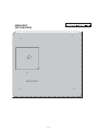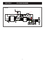
1
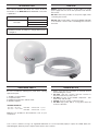
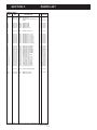
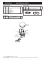
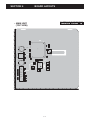
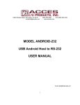
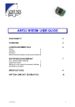
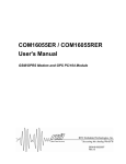
GPS RECEIVER
S-14710XZ-C1
Sep. 2010
INTRODUCTION
CAUTION
This service manual describes the latest technical
information for the MXG-5000 GPS RECEIVER, at the time
of publication.
MODEL
DO NOT reverse the polarities of the power supply when
connecting the receiver.
VERSION
DO NOT apply an RF signal of more than 20 dBm (100 mW)
to the antenna connector. This could damage the receiver’s
front-end.
EXP
USA
MXG-5000
NEVER connect the receiver to an AC outlet or to a DC
power supply that uses more than specified. This will ruin
the receiver.
EUR
To upgrade quality, any electrical or mechanical parts
and internal circuits are subject to change without notice
or obligation.
REPAIR NOTES
ORDERING PARTS
Be sure to include the following four points when ordering
replacement parts:
1. 10-digit Icom part number
2. Component name
3. Equipment model name and unit name
4. Quantity required
<ORDER EXAMPLE>
8900018230
OPC-1886
MXG-5000
CHASSIS UNIT
2 pieces
8510012351
2273 U-CASE-1 MXG-5000
CHASSIS UNIT
3 pieces
1. Make sure that the problem is internal before
disassembling the receiver.
2. DO NOT open the receiver until the receiver is
disconnected from its power source.
3. DO NOT force any of the variable components. Turn
them slowly and smoothly.
4. DO NOT short any circuits or electronic parts.
5. DO NOT keep power ON for a long time when the
receiver is defective.
Addresses are provided on the inside back cover for your
convenience.
Icom, Icom Inc. and the Icom logo are registered trademarks of Icom Incorporated (Japan) in Japan, the United States, the
United Kingdom, Germany, France, Spain, Russia and/or other countries.
TABLE OF CONTENTS
SECTION
1
SPECIFICATIONS
SECTION
2
INSIDE VIEWS
SECTION
3
PARTS LIST
SECTION
4
MECHANICAL PARTS
SECTION
5
BOARD LAYOUTS
SECTION
6
BLOCK DIAGRAM
SECTION
7
VOLTAGE DIAGRAM
SECTION 1.
• Power supply voltage
• Operating temp. range
• Relative humidity
• Dimensions
• Weight (approx.)
• Cable length (approx.)
• Receiving frequency
• Receiving channels
• Receiving codes
• Satellite differential type
• TTFF (Time to First Fix)
Cold start (typical)
Hot start (typical)
SPECIFICATIONS
: 4.75 to 5.25 V DC (supplied from the MarineCommander™)
: −20˚C to +60˚C; −4˚F to +140˚F
: Less than 95% (at +35˚C; +95˚F)
: 140(d)×157.2(H) mm; 51⁄2(d)×63⁄16(H) in.
: 710 g; 1.57 oz
: 10 m; 32 ft. 93⁄4 in.
: 1575.42 MHz
: 12
: L1, C/A-code, SPS
: WAAS, EGNOS, MSAS
: 40 sec.
: 4 sec.
All stated specifications are subject to change without notice or obligation.
1-1
SECTION 2.
INSIDE VIEWS
• MAIN UNIT
(TOP VIEW)
3.3 V REGULATOR
(IC2)
GPS RECEIVER MODULE
(IC3)
RS-232 LINE DRIVER
(IC1)
BPF
(FI1)
• MAIN UNIT
(BOTTOM VIEW)
GPS ANTENNA
(EP3)
2-1
SECTION 3.
PARTS LIST
[MAIN UNIT]
REF
NO.
IC1
IC2
IC3
PARTS
NO.
DESCRIPTION
H/V
M. LOCATION
1120002951 S.IC
UPD4721GS-GJG-A
1180002020 S.REG BA033FP-E2
1190002581 S.IC
ITRAX03S1/IT03S341EPPS1677
<MRF
T
T
28.5/30.0
8.0/41.0
T
27.0/48.5
D1
D2
D3
D4
D5
1730002331
1730002331
1730002331
1730002331
1790001711
MAZ8100GML
MAZ8100GML
MAZ8100GML
MAZ8100GML
NNCD5.6C-T1-A
T
T
T
T
T
10.8/20.2
10.8/16.7
11.5/13.8
11.5/10.4
10.5/25.1
FI1
2020002550 S.DIE
TDFM2A-1575A-10A
T
40/46.7
R1
R2
R3
R4
R5
R6
R7
R8
R9
7030003200
7030003200
7030003560
7030003560
7030003360
7030003360
7030003360
7030003360
7030003520
S.RES
S.RES
S.RES
S.RES
S.RES
S.RES
S.RES
S.RES
S.RES
ERJ3GEYJ 100 V (10)
ERJ3GEYJ 100 V (10)
ERJ3GEYJ 103 V (10K)
ERJ3GEYJ 103 V (10K)
ERJ3GEYJ 221 V (220)
ERJ3GEYJ 221 V (220)
ERJ3GEYJ 221 V (220)
ERJ3GEYJ 221 V (220)
ERJ3GEYJ 472 V (4.7K)
T
T
T
T
T
T
T
T
T
22.3/31.5
22.3/32.8
25.0/35.9
23.7/35.9
17.6/56.2
36.4/40.5
37.7/40.5
17.5/48.2
17.6/59.0
C1
C2
C3
C4
C5
C6
C7
C8
C9
C10
C11
C13
C14
C15
C16
C17
C18
C19
C20
4550007960
4550007090
4030006900
4550007960
4550007960
4550007960
4550007960
4510009030
4030006900
4510009030
4030006900
4030007130
4030007130
4030006900
4030006900
4030006900
4550007090
4030006900
4030017810
S.TAN
S.TAN
S.CER
S.TAN
S.TAN
S.TAN
S.TAN
S.ELE
S.CER
S.ELE
S.CER
S.CER
S.CER
S.CER
S.CER
S.CER
S.TAN
S.CER
S.CER
TEESVB2 1E 475M8R
TEESVA 1A 226M8R
C1608 JB 1H 103K-T
TEESVB2 1E 475M8R
TEESVB2 1E 475M8R
TEESVB2 1E 475M8R
TEESVB2 1E 475M8R
EEE0JA101SP
C1608 JB 1H 103K-T
EEE0JA101SP
C1608 JB 1H 103K-T
C1608 CH 1H 101J-T
C1608 CH 1H 101J-T
C1608 JB 1H 103K-T
C1608 JB 1H 103K-T
C1608 JB 1H 103K-T
TEESVA 1A 226M8R
C1608 JB 1H 103K-T
C1608 CH 1H 102J-T
T
T
T
T
T
T
T
T
T
T
T
T
T
T
T
T
T
T
T
38.6/24.5
30.1/36.2
26.3/35.9
38.6/28.6
38.6/32.4
27.7/23.7
20.9/27.0
8.0/32.5
10.6/36.8
8.0/49.5
10.6/45.2
12.5/16.4
11.5/12.1
11.9/25.8
17.6/43.5
36.4/53.7
39.5/53.7
18.4/37.9
36.4/48.7
J2
6510018951 S.CON B7B-PH-SM4-TB(LF)(SN)
T
7.0/19.0
EP2
EP3
6910012350 S.BEA
6910019890 E.O
T
17.6/40.7
S.ZEN
S.ZEN
S.ZEN
S.ZEN
S.DIO
MMZ1608Y 102BT
#DAKC1575MS74T
M.=Mounted side (T: Mounted on the Top side, B: Mounted on the Bottom side)
S.=Surface mount
3-1
SECTION 4.
MECHANICAL PARTS
[CHASSIS PARTS]
REF
NO.
ORDER
NO.
[ACCESSORIES]
DESCRIPTION
W1
8900018230 OPC-1886 <LIA>
1
MP1
MP2
MP3
MP11
MP13
MP14
MP15
8510012340
8930049320
8810008661
8510012351
8930049392
8820001210
8930052290
1
1
4
1
1
4
4
2273 L-CASE
2288 VENT.SHEET
PHBT M3 X 8 NI-ZC3
2273 U-CASE-1
2273 MAIN SEAL-2 (TOT)
2438 SCREW
O-RING (AD) (TOP)
REF
NO.
QTY.
MP1
MP2
ORDER
NO.
DESCRIPTION
8930049400 2273 PIPE
8930049740 HAS-40 (X-2272-3) STAINLESS BAND
MP1
MP2
[MAIN UNIT]
REF
NO.
J2*
ORDER
NO.
DESCRIPTION
6510018951 B7B-PH-SM4-TB (LF) (SN)
QTY.
1
MP11(C)
MP13(C)
MP3(C)
MAIN UNIT
W1(C)
J2(M)
MP2(C)
MP1(C)
MP15(C)x4
MP14(C)x4
*: Refer to “BOARD LAYOUTS” for the location.
Screw abbreviations
A, B0, BT: Self-tapping PH: Pan head ZK: Black NI-ZU: Nickel-Zinc SUS: Stainless
4-1
QTY.
1
2
SECTION 5.
BOARD LAYOUTS
The combination of top side and bottom side of this
C18
C17
V55
R5
R9
V60
V65
V70
• MAIN UNIT
(TOP VIEW)
V50
CP1
R8
IC3
C20
C10
V45
FI1
R7
R6
EP2
V40
IC2
C16
C11
C19
R3
C2
C3
V35
R4
C9
R2
C8
C5
IC1
V30
R1
C4
C15
1
GPS5V
D5
V25
C7
J2
C1
C6
D1
GND
J2
V15
GND-G5
D2
GPSTXD
C13
V20
GPSGND
GPSRXD
D3
GPS-D7
V10
C14
H65
H60
H55
H50
H45
H40
H35
5-1
H70
H30
H25
H20
H15
H10
H5
V0
V5
D4
H0
The combination of top side and bottom side of this
• MAIN UNIT
(BOTOM VIEW)
V70
1
V65
3
V60
V55
V50
V45
V40
V35
V30
EP3
V25
V20
B6980B
V15
V10
2
4
V5
V0
H0
H5
H10
H15
H20
H25
H30
H35
5-2
H40
H45
H50
H55
H60
H65
H70
SECTION 6.
BLOCK DIAGRAM
IC2
BA033FP
3.3V
3.3 V
regulator
GPS5V
GPS antenna
EP3
#DAKC1575MS74T
FI1
TDFM2A-1575A-10A
IC3
ITRAX03-S-1
IC1
UPD4721GS
GPSTXD
BPF
GPS receiver module
RS-232 line driver
GPSRXD
6-1
SECTION 7.
VOLTAGE DIAGRAM
• MAIN UNIT
EP3
#DAKC1575MS74T
FI1
TDFM2A-1575A-10A
I
O
3.3V
5.0V
CP1
R8
220
3.3V
C16
0.01
C19
0.01
IC3
ITRAX03-S-1
1
2
3
4
5
6
7
8
9
10
11
12
13
14
15
TCAP1
BOOT1
SPI1XCS0
SPI1SDO
GND
SPI1SDI
SPI1CLK
GND
XRESET
BOOT2
GND
SPI1XCS2
MMCCMD
VDDRF
GND
30
29
28
27
26
25
24
23
22
21
20
19
18
17
16
GPS5V
I
G
C11
0.01
C9
C8
0.01 100
C3
0.01
C2
22
PPS
PM0
VDDDIG
MMCDAT
GND
GND
RFIN
GND
GND
MMCCLK
GND
RXD1
RXD0
TXD0
TXD1
O
C10
100
3.3V
C17 C18
0.01 22
3.3V
IC1
UPD4721GS-A
C1
4.7
C4
4.7
C20
0.001
R6
220
R7
220
3.3V
C5
4.7
1
2
3
4
5
6
7
8
9
10
VDD
CI+
VCC
CIC5+
C5DIN1
DIN2
ROUT1
ROUT2
C4+
GND
C4VSS
STBY
VCHA
DOUT1
DOUT2
RIN1
RIN2
20
19
18
17
16
15
14
13
12
11
C6
4.7
C7
4.7
R4
10K
R1
10
R3
10K
J2
R2
10
D1
DZ2J100M
C13
100P
C14
100P
D2
DZ2J100M
7-1
GPS5V
GPSGND
GND
GPSTXD
GND-G5
GSPRXD
GND-D7
D3
DZ2J100M
C15
0.01
D5
D4
DZ2J100M NNCD5.6C-A
1
2
3
4
5
6
7
8
R5
220
3.3V
9
R9
4.7K
IC2
BA033FP
EP2
MMZ1608Y102BT
3.3V
1-1-32, Kamiminami, Hirano-ku, Osaka 547-0003, Japan
Phone : +81 (06) 6793 5302
Fax
: +81 (06) 6793 0013
URL : http://www.icom.co.jp/world/index.html
<Corporate Headquarters>
2380 116th Avenue N.E., Bellevue, WA 98004, U.S.A.
Phone : +1 (425) 454-8155
Fax : +1 (425) 454-1509
URL : http://www.icomamerica.com
E-mail : [email protected]
<Customer Service>
Phone : +1 (425) 454-7619
Glenwood Centre #150-6165
Highway 17 Delta, B.C., V4K 5B8, Canada
Phone : +1 (604) 952-4266
Fax : +1 (604) 952-0090
URL : http://www.icomcanada.com
E-mail : [email protected]
Unit 1 / 103 Garden Road, Clayton VIC 3168 Australia
Phone : +61 (03) 9549-7500
Fax : +61 (03) 9549-7505
URL : http://www.icom.net.au
E-mail : [email protected]
146A Harris Road, East Tamaki,
Auckland, New Zealand
Phone : +64 (09) 274 4062
URL : http://www.icom.co.nz
E-mail : [email protected]
Fax : +64 (09) 274 4708
81-850 Sopot, ul. 3 Maja 54, Poland
Phone : +48 (58) 550 7135
Fax : +48 (58) 551 0484
E-mail : [email protected]
Communication Equipment
Auf der Krautweide 24
65812 Bad Soden am Taunus, Germany
Phone : +49 (6196) 76685-0
Fax : +49 (6196) 76685-50
URL : http://www.icomeurope.com
E-mail : [email protected]
Ctra. Rubi, No. 88 Bajos A 08174, Sant Cugat del Valles, Barcelona, Spain
Phone : +34 (93) 590 26 70
Fax : +34 (93) 589 04 46
URL : http://www.icomspain.com
E-mail : [email protected]
Blacksole House, Altira Park, Herne Bay, Kent CT6 6GZ, UK
Phone : +44 (01227) 741741
Fax : +44 (01227) 741742
URL : http://www.icomuk.co.uk
E-mail : [email protected]
Zac de la Plaine
1 Rue Brindejonc des Moulinais BP 5804
31505 Toulouse Cedex, France
Phone : +33 (5) 61 36 03 03
Fax : +33 (5) 61 36 03 00
URL : http://www.icom-france.com
E-mail : [email protected]
6F No.68, Sec. 1 Cheng-Teh Road, Taipei, Taiwan, R.O.C.
Phone : +886 (02) 2559 1899
Fax : +886 (02) 2559 1874
URL : http://www.asia-icom.com
E-mail : [email protected]
1-1-32, Kamiminami, Hirano-ku, Osaka 547-0003, Japan
S-14710XZ-C1
© 2010 Icom Inc.