1
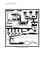
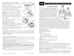
MANOMETRIC PUMP ELECTRICALLY POWERED MODEL OPERATING AND SERVICE MANUAL FOR MODEL NUMBERS PIP-4-4 PIP-4-4SS PIP-4-6 PIP-4-6SS PIP-4-8 PIP-4-8SS PIP-4-12 PIP-4-12SS PIP-4-16 PIP-4-16SS Mui Scientific 145 Traders Blvd. E., Unit #33-34 Mississauga, Ontario, Canada L4Z 3L3 Tel: (905) 890-5525 Toll Free: (800) 303-6611 Fax: (905) 890-3523 Email: [email protected] Website: www.muiscientific.com EC REP Advena Ltd. Pure Offices, Plato Close, Warwick, CV34 6WE, United Kingdom Manual P4-F-100, Revised June 6, 2013 CAUTION: Federal law (U.S.) restricts the sale of this device to, or by the order of a physician. READ ENTIRE MANUAL BEFORE OPERATING MANOMETRIC PUMP ii Table of Contents Section 1 INTRODUCTION 1 Section 2 DESCRIPTION OF MANOMETRIC PUMP 2.1 Physical Description 2.2 General Requirements 2.3 Diagram of Features 2.4 Certification, Classification and Warning Statements Certification 2 3 4 9 Section 3 Section 4 Section 5 Section 6 Section 7 Section 8 INITIAL INSTALLATION 3.1 Initial Assembly 3.2 Placement of Water Chamber 3.3 Connecting Electrical System 3.4 Installation of Transducers 3.5 Installation of Stopcocks 3.6 Installation of Calibration System 11 11 11 12 14 15 PREPARATION PROCEDURES 4.1 Filling the Water Chamber 4.2 Selecting Water Chamber Pressure 4.3 Adjusting Water Chamber Pressure 4.4 Purging Air from Pump and Transducers 4.5 Calibration of Recording System 4.6 Functional Check - Pinch Test 16 19 20 21 23 24 OPERATION 5.1 Normal Operation Before and During the Study 5.2 Functional Troubleshooting with the Pinch Test 5.3 Calculation of Pressure Rise Rate 5.4 Post Study: Daily Blow-Dry Shut-Down Procedure 25 26 28 29 SERVICE: MAINTENANCE 6.1 Daily Blow-Dry Shut-Down Protocol 6.2 High-Level Disinfection 6.3 High-Level Disinfecting Procedure 6.4 Care and Cleaning of Your Manometric Pump 6.5 Replacing the Capillary Tubing 6.6 Inspecting the Drying Cylinder 6.7 Drying the Desiccant 30 31 31 33 33 34 34 SERVICE: TROUBLESHOOTING 7.1 Poor Pressure Rise Rate or No Signal Response 7.2 Compressor Motor Does Not Run 7.3 Compressor Motor Runs Too Often or Does Not Shut Off 35 35 36 PARTS LIST 37 iii List of Illustrations Table Title Page 1 Water Chamber Pressure Selection vs Infusion Rate/Pressure Rise Rate 4.2 19 2 Pressure Conversion Chart 4.2 19 Section Page Figure iv Section Title 1 Diagram of Manometric Pump 2.3 4 2 Air-Water System of AC Pump 2.3 5 3 Block Diagram of AC Pump 2.3 6 4 Electrical Compartment Removal 2.3 7 5 Electrical Schematic 2.3 8 6 Electrical Compartment 2.3 8 7 Universal Transducer Holder Assembly 3.4 12 8 Medex/pvb Transducer Holder Assembly 3.4 13 9 Installation of Stopcocks on Transducer 3.5 14 10 Alternate Connection to Transducer 3.5 14 11 Hydrostatic Calibration System (0–50/68 cm H2O) 3.6 15 12 Master On-Off Valve 4.1 16 13 Bottom Quick-Connect and Filter on Water Chamber 4.1 17 14 Air Quick-Connect on Top of Water Chamber 4.1 18 15 Stopcock Manifold 4.4 21 16 Purging Air from System Using a Syringe 4.4 22 17 Hydrostatic Calibration System (0-50/68 cm H2O) 4.5 23 18 Pinch Test: Pinch Point and Output Graph 4.6 24 19 Infusion Artifact 5.1 25 20 Slow Pressure Rise Rate 5.2 27 21 Calculation of Pressure Rise Rate 5.3 28 1 Introduction This Manometric Pump is part of the motility system used for intraluminal manometric studies of the gastrointestinal tract, such as pressure measurement of muscular contractions or resting tone inside the esophagus, stomach, bile duct, small intestine, anus, rectum, or colon. Other components of this system include a set of pressure transducers, a motility catheter, and a computerized data processing system or a chart recorder. The Electrically Powered Manometric Pump uses regulated compressed air to deliver distilled water through very small bore capillary tubing to the motility catheter. The pressurized water from each capillary tube is connected to a pressure transducer and then passes through one lumen of the multi-lumen catheter to that lumen’s single opening into the esophagus of the patient. The pressure changes in the esophagus are transmitted through this fluid path back to the externally mounted transducer; i.e. the water serves as a pressure - transmission medium. Each lumen of the motility catheter is connected to its own pressure transducer and all the pressure transducers are connected to a computerized recording system or a strip chart recorder. The pressure profile of the multi-channel tracing provides useful diagnostic data for evaluation of the normal or abnormal motor function of the gastrointestinal tract. Similar applications include pressure measurements for oropharygeal, esophageal, stomach, intestinal, colonic, anorectal and biliary motility studies. This Manometric Pump is designed to operate at a constant pressure rather than at a constant flow rate. It maintains a pre-set hydraulic pressure (5-15 psi) at the water chamber regardless of the flow. At 15 psi (776 mm Hg) the pump provides a high static hydraulic pressure background to ensure a high pressure rise rate as well as recording accuracy and repeatability. It can record fast pressure changes such as in the upper esophageal sphincter. The small bore of the capillary tube also ensures a very low infusion rate. During a motility study, the actual flow rate varies due to the varying amount of obstruction caused by muscle contractions. The pressure rise rate of the pump, measured as pressure change per unit of time (i.e. mm Hg/sec or cm H2O/sec), varies directly with the water chamber pressure. A higher water chamber pressure will result in a higher pressure rise rate but also a higher flow rate. To achieve measurement accuracy, the pressure rise rate of the recording system must exceed the actual physiological rise rate of the organ. The upper esophageal sphincter has the highest muscular contraction rate of the gastrointestinal tract. A study of this organ requires the highest pressure rise rate of the recording system, 400 mm Hg/sec. The recommended water chamber pressure of 15 psi (pounds per square inch) will achieve a pressure rise rate of 400 mm Hg/sec. The main purpose of reducing the water chamber pressure from 15 to 5 psi is to reduce the infusion rate from 0.6 to 0.3 ml/min. The lower water chamber pressure and lower pressure rise rate still permit reliable measurement accuracy on those organs that have a lower physiological contraction rate. The pump allows the operator to change the water chamber pressure for different physiological applications in order to optimize the pressure rise rate and flow rate. An infusion rate table (Table 1, Section 4.2) is provided to enable an estimate of the total volume of water infused into the patient in a given period of time. 1 2 2.1 Description of Manometric Pump PHYSICAL DESCRIPTION The Electrically Powered Manometric Pump consists of an air compressor and a pressure regulator inside a stainless steel case. The air supply pressurizes a water chamber, which delivers pressurized water to a stopcock manifold, which connects in turn to a set of capillary tubes. A set of transducer holders is located on an adjustable support bar. The transducers and motility catheters (which are not supplied with pump) are mounted in the transducer holders and connected to the capillary tubes. The drying cylinder inside the stainless steel case removes moisture from the pressurized air and serves as a high pressure air reservoir (17-40 psi). Then the pressurized air is regulated with a manually adjustable regulator. This sets the final pressure in the water chamber (5–15 psi). The compressor gauge (left side) shows the high pressure in the drying cylinder. The water chamber gauge (right side) shows the pressure in the water chamber. The white pilot light indicates the main power status, ON/OFF. The green pilot light indicates the compressor status, ON/OFF. The water chamber is removable, simply resting inside the water chamber holder. It is equipped with quick disconnects for the air from the top and for a filtered water connection outlet at the bottom. The lid of the chamber is removable to facilitate filling and cleaning. A toggle valve is provided for quick release of the chamber pressure. The chamber float acts as a barrier to minimize air absorption into the water. A master on-off valve controls the water flow from the water chamber to the stopcock manifold. The 4-way stopcocks on the manifolds provide individual on-off control of the water flow to each capillary tube. The outlet end of each capillary tube is equipped with a standard male luer connector for easy connection to the transducer. If required, a female-female luer adaptor is provided for conversion of the luer connections. The transducer holders (various types are available) keep the transducers in place and level. The adjustable support permits proper positioning of the height of the transducers with respect to the patient. 2 DESCRIPTION OF MANOMETRIC PUMP 2.2 2 GENERAL REQUIREMENTS The Manometric Pump should be mounted on a cart or shelf at approximately the same height as the patient’s bed. The height of the transducers should be level with the height of the patient’s stomach. This will reduce the hydrostatic pressure artifact on the transducer and on the recording. The Manometric Pump is normally placed near the bedside close to the patient’s head. CAUTION: No electrical equipment should be located beneath the Manometric Pump. Some water from the motility catheter is likely to drip down during the procedure. A danger of electric shock could result. CAUTION: Use only sterilized irrigation water in the water chamber. Never use tap water as it contains minerals which can cause blockages in tubing and/or can support bacterial growth. Electrical requirements: (a) 115 Volt Model: A grounded, hospital grade, 115 Volt, 60 Hz, 15A electrical outlet is required. The pump is rated at 2A. Hospital grade power cord with IEC plug is included. (b) 220 Volt Model: A grounded, hospital grade, 220 Volt, 50 Hz electrical outlet is required. The pump is rated at 2A. Hospital grade power cord with female IEC plug is required. (c) 240 Volt Model: A grounded, hospital grade, 240 Volt, 50 Hz electrical outlet is required. The pump is rated at 2A. Hospital grade power cord with female IEC plug is required. Over-all dimensions: Height (including water chamber) ----------------------Width (4, 6 and 8 channel models) --------------------Width (12 channel model) --------------------------------Depth (transducer holders attached) ------------------Length of AC power cord (115v only) ------------------ 50 cm (20 inches) 56 cm (22 inches) 69 cm (27 inches) 33 cm (13 inches) 240 cm (94 inches) Weight: Net weight (4, 6 and 8 channel models) --------------Net weight (12 channel models) ------------------------- 14 kg (30 pounds) 15 kg (32 pounds) 3 DESCRIPTION OF MANOMETRIC PUMP 2.3 2 DIAGRAM OF FEATURES Figure 1. Diagram of Manometric Pump (8-channel model shown) 4 DESCRIPTION OF MANOMETRIC PUMP 2 Figure 2. Air-Water System of AC Pump 5 DESCRIPTION OF MANOMETRIC PUMP 2 Figure 3. Block Diagram of AC Pump 6 DESCRIPTION OF MANOMETRIC PUMP 2 Figure 4. Electrical Compartment Removal WARNING: DISCONNECT POWER CORD AND RELEASE ALL AIR PRESSURE BEFORE DISASSEMBLING THE MANOMETRIC PUMP. ELECTRIC COMPARTMENT REMOVAL: 1. DISCONNECT POWER CORD AND RELEASE ALL AIR PRESSURE. 2. REMOVE THE WATER CHAMBER FROM THE MANOMETRIC PUMP. 3. REMOVE 7 SCREWS AT THE LEFT END OF THE PUMP CASING AND 2 SCREWS AT THE BOTTOM OF THE PUMP CASING AS SHOWN. 4. SLIDE THE ELECTRICAL COMPARTMENT OUT IN THE DIRECTION OF THE ARROW. 5. DISCONNECT THE AIR HOSES AT THE DRYING CYLINDER QUICK DISCONNECTS. OPENING ELECTRIC COMPARTMENT: A. REMOVE 3 SCREWS FROM THE FRONT PANEL AND 5 SCREWS FROM THE TOP PANEL OF THE ELECTRIC COMPARTMENT AS SHOWN. B. LIFT THE TOP PANEL (WITH THE DRYING CYLINDER ATTACHED) TO EXPOSE THE INTERIOR OF THE ELECTRIC COMPARTMENT. 7 DESCRIPTION OF MANOMETRIC PUMP 2 Figure 5. Electrical Schematic Figure 6. Electrical Compartment 8 DESCRIPTION OF MANOMETRIC PUMP 2.4 2 CERTIFICATION, CLASSIFICATION, AND WARNING STATEMENTS CERTIFICATION Europe 0120 EMC Directive Medical Device Directive 89/336/EEC 93/42/EEC Authorized Representative of Mui Scientific in EU: Emergo Europe Molenstraat 15 2513 BH, The Hague The Netherlands Tel: +31.70.345.8570 Fax: +31.70.346.7299 International IEC 601-1:1988 IEC 601-1:1988 Am 1:1991 IEC 801.2, 801.3, 801.4, 801.5 EN55011 (C.I.S.P.R. 11 (1990) Group1 Class B) Mui Scientific, at 145 Traders Blvd. E., Unit #34, Mississauga, Ontario, Canada, is registered to ISO 13485: 2003 International Standard for Quality Management Systems (for Medical). Canada CAN/CSA - C22.2 No. 0-M91 CAN/CSA - C22.2 No. 601.1-M90 CAN/CSA - C22.2 No. 601.1S1-94 United States UL Std. No. 544 Equipment Classification Class I with respect to protection from electric shock. Type BF with respect to degree of protection from electric shock. Ordinary degree of protection against ingress of liquids. Equipment not suitable for use in the presence of a flammable anaesthetic mixture with air or with nitrous oxide. Mode of operation: continuous. 9 DESCRIPTION OF MANOMETRIC PUMP 2 Warning Statements and Warning Symbols Type BF Equipment DANGER: EQUIPMENT NOT SUITABLE FOR USE IN THE PRESENCE OF A FLAMMABLE ANAESTHETIC MIXTURE GROUND RELIABILITY CAN ONLY BE ACHIEVED WHEN THE EQUIPMENT IS CONNECTED TO A RECEPTACLE MARKED “HOSPITAL ONLY” OR “HOSPITAL GRADE” Note: All models (115v, 220v, 240v) require 2 fuses: 5 x 20 mm, 250v, T2A. Environmental Conditions for Storage or Transport When packed for transport from factory, equipment will withstand 10 ambient temperature range -40C to +70C relative humidity range 10% to 100% atmospheric pressure range 500 kPa to 1060 kPa 3 Initial Installation 3.1 INITIAL ASSEMBLY Remove any remaining packing material. Place the pump main assembly on a table and make the following adjustments: Adjust the height of the hexagonal transducer support bar: Loosen the rear knurled screws on the support bar holder that mounts the hexagonal transducer support bar. Adjust the height of the support bar so that the transducers will be level with the approximate height of the patient’s stomach during a study. Retighten the knurled screws. Adjust the orientation of the hexagonal bar: Loosen the front knurled screws on the holder that mounts the hexagonal transducer support bar on the front of the Manometric Pump. Rotate the bar until the transducer holders are in a horizontal position. Retighten the screws. Adjust the spacing of the transducer holders: Loosen the rear knurled screws on the transducer holders and space the transducer holders evenly along the hexagonal bar. Retighten the screws securely. If necessary, the transducer holders can be removed by sliding them off the end of the hexagonal bar. Check that the pointer in both gauges is at zero position. CAUTION: After shipment, pointer may not rest at zero due to internal case pressure buildup caused by temperature variations. Accuracy may be significantly reduced. To restore gauge to operating condition, move lever of fill plug to the “open” position. 3.2 PLACEMENT OF WATER CHAMBER Place the water chamber into the plastic holder on top of the Manometric Pump, lining up the water quick-connect pointing to the left on the bottom of the water chamber with the slot in the holder (Figure 13, Section 4.1). The plastic holder enables one person to easily remove or tighten the lid of the water chamber. Unscrew the lid of the water chamber. Discard any packing material. Check that the O-ring is lightly greased (with petroleum jelly). Replace lid back onto water chamber. 3.3 CONNECTING ELECTRICAL SYSTEM Ensure that the main power switch (at the bottom of the left side panel of the Manometric Pump) is in the OFF position. Plug the grounded AC power cord (hospital grade) into the IEC power entry that is next to the main power switch. Connect the power cord to a grounded electrical outlet. 11 INITIAL INSTALLATION 3.4 3 INSTALLATION OF TRANSDUCERS A. Universal Transducer Holder Installation If the pump is supplied with the Universal Transducer Holder Assembly, then use the following steps to install transducers (not supplied) on the Manometric Pump: Position the universal transducer holders horizontally. Loosen the 2 front knurled screws on the universal transducer holder. Slide the transducer between the front bracket and the V-shaped cutout in the holder as shown in Figure 7(a), 7(c). To hold a smaller diameter transducer, remove the 2 front knurled screws completely and reverse the front bracket of the transducer holder as shown in Figure 7(b). Clamp the transducer in the holder assembly by retightening the two knurled screws against the front bracket. CAUTION: Do not over-tighten the knurled screws against the front bracket. Damage to the transducer may result. Figure 7. Universal Transducer Holder Assembly 12 INITIAL INSTALLATION 3 B. Medex/pvb Transducer Holder Installation If your pump is supplied with the Medex or pvb Transducer Holder Assembly, as shown in Figure 8, simply slide the transducer into the slot on the transducer holder plate from the top. The transducer holder plate can be repositioned by loosening and tightening the knurled thumbscrews at the back of the assembly. Figure 8. Medex/pvb Transducer Holder Assembly 13 INITIAL INSTALLATION 3.5 3 INSTALLATION OF STOPCOCKS Install plastic stopcocks (not supplied) to the input and output ports of the transducers and attach capillary tubes as shown in Figure 9, to aid in the purging of air bubbles. The most common cause of loss of recording accuracy in a motility system is air bubbles trapped in the transducer or in the motility catheter. Figure 9 shows the way to connect the transducers to the Manometric Pump and the catheter when using a large syringe. This setup requires additional 2-way and 4-way stopcocks for each transducer. Ample water under pressure can be flushed from the bottom to the transducer in order to push any air bubbles up and out the top of the transducer. This method ensures that the transducer and catheter are free of air bubbles in the shortest time possible. Figure 9. Installation of Stopcocks on Transducer Another method of connection is shown in Figure 10. The small flow from the capillary tube will require more time to flush out all the small air bubbles, and may not be very efficient. Figure 10. Alternate Connection to Transducer 14 INITIAL INSTALLATION 3.6 3 INSTALLATION OF CALIBRATION SYSTEM Installation of Hydrostatic Calibration System (0-50/68 cm H2O) 0-50 cm H2O System, Part #P4-H-610 0-68 cm H2O System, Part #P4-H-620 On the square calibration rod locate the two white plastic tube-holders. Slide a clear plastic 11-inch tube into the hole of each tube-holder as shown in Figure 11, below. Tighten the knurled screw to secure the clear plastic tube. Slide the square calibration rod into the two calibration rod holders on the right-hand round support bracket. The clear plastic tubes should be oriented perpendicular to the pump as shown in Figure 11. The lower clear plastic tube should be at the same level as the transducers for 0 cm H2O or low calibration. The upper plastic tube is for 50 or 68 cm H2O for high calibration (68 cm H2O = 50 mm Hg). Figure 11. Hydrostatic Calibration System (0–50/68 cm H2O) 15 4 Preparation Procedures Section 4 describes all of the procedures required to prepare the pump for motility studies and routine maintenance. 4.1 FILLING THE WATER CHAMBER Turn the master on-off valve to the OFF position. Place the water chamber into the plastic holder on top of the pump, lining up the bottom quick-connect on the water chamber pointing to the left with the slot in the holder. Unscrew the lid of the water chamber and remove the round float by grasping the knob. Ensure that the inside of the water chamber is clean. Fill three-quarters full with sterilized irrigation water only. CAUTION: Never use tap water as it contains minerals which can cause blockages in tubing and/or support bacterial growth. Replace the float in the water chamber at an angle to avoid any bubbles being trapped under the float. CAUTION: Never use the pump without the float in the water chamber. Air bubbles will form at the transducer and will reduce the pressure response rate and the accuracy of measurement. Screw the lid back on and tighten securely. Figure 12. Master On-Off Valve 16 Preparation Procedures 4 Attach the bottom plastic quick-connect located at the bottom of the water chamber (Figure 13 below). Connect the bottom quick-connect on the water chamber by pressing the metal tab on the water chamber connector and pushing the elbow connector in until it snaps (Figure 13a below). This connection delivers pressurized water from the water chamber through the master onoff valve into the stopcock manifold and into the capillary tubes. A stainless steel filter on the quick-connect inside the water chamber filters all water delivered to the capillary tubes. To disconnect the quick-connect, push down on the metal tab and pull the elbow connector out. The water flow will automatically shut off at both ends of the quick connect (Figure 13b below). Figure 13. Bottom Quick-Connect and Filter on Water Chamber TO CONNECT: Make sure that the metal tab is down. Insert the elbow quick connect and push it in until the metal tab snaps up into the lock position. TO DISCONNECT: Push down on the metal tab and pull the elbow quick connect out. 17 Preparation Procedures 4 Connect the top metal quick-connect located on the lid of the water chamber (Figure 14 below) pushing the two metal fittings together until they snap into the latched position. This connection delivers compressed air from the pressure regulator to the water chamber. To release the quick-connect, push down on the flange. When disconnected, air pressure in the water chamber is released and air flow from the compressor is shut off at the tubing end of the quick connect. The toggle pressure release valve as shown in Figure 14 below is in the normal CLOSED position. To OPEN the valve squeeze the black handle toward the body of the valve. The valve opens momentarily to release pressure from the system. Figure 14. Air Quick-Connect on Top of Water Chamber TO CONNECT: Push down on the body until connection snaps together. The gap between the body and the flange will disappear. 18 TO DISCONNECT: Push down on the flange until the body of the quick connect pops up and disconnects. Lift the connector body off the post. Preparation Procedures 4.2 4 SELECTING WATER CHAMBER PRESSURE To select water chamber pressure for optimal recording accuracy of pressure rise rate for your recording site or organ, refer to the table below and adjust the water chamber pressure accordingly. The associated infusion rate is provided in the table to enable a quick estimate of the total volume of water infused into the patient in a given period of time. 15 psi is the recommended pressure for esophageal and upper esophageal sphincter studies. For a small bowel study, the pressure should be set at 7 psi. For a colon study, the pressure can be as low as 5 psi. CAUTION: Do not set water chamber pressure higher than 20 psi. Damage to system could result. Patient will receive excessive water. Table 1. Water Chamber Pressure Selection vs Infusion Rate/Pressure Rise Rate RECORDING SITE (ORGAN) APPROXIMATE INFUSION RATE WITH STANDARD CAPILLARY TUBE ml/min RECOMMENDED WATER CHAMBER PRESSURE MINIMUM PRESSURE RISE RATE AT CATHETER OPENING UES 0.6 pound/square inch (kPa) 15 (103) mm Hg/sec Esophagus 0.6 15 (103) 400 Stomach 0.6 15 (103) 400 Small Bowel 0.4 7 (48) 120 Bile Duct 0.4 7 (48) 120 Colon 0.3 5 (35) 60 400 Table 2. Pressure Conversion Chart Psi cm of H2O mm of Hg kPa 20 1408 1034 138 15 7 5 1056 493 352 776 362 259 103 48 35 19 Preparation Procedures 4.3 4 ADJUSTING WATER CHAMBER PRESSURE Check that the master on-off valve is at the OFF position (Figure 12, Section 4.1). Turn the main power switch to the ON position. When the main power switch is turned on, both pilot lights (white and green) will illuminate and the compressor will run. The pressure on both gauges will rise. After a few minutes the compressor should stop and the green compressor pilot light should turn off. The compressor pressure gauge (left side) should be at 40 psi or higher. The white power pilot light remains lit, indicating that the main power is still on. The compressor gauge indicates the pressure in the high pressure drying cylinder inside the pump. In normal operation as water empties from the water chamber it is replaced by compressed air. The compressor pressure gauge will drop slowly from approximately 40 psi to 17 psi. When the pressure has fallen to 17 psi, the compressor will turn on for a few minutes until it reaches 40 psi again (to maintain a constant water chamber pressure). The water chamber gauge (right side) shows the regulated pressure delivered to the water chamber. This is normally set at 15 psi and remains constant. (For other pressure settings see Table 1, Section 4.2). Adjust the black regulator control knob until the water chamber gauge (on the right hand side of the pump) indicates 15 psi. The black regulator control knob is located on the top of the pump on the right hand side. It controls the pressure regulator that is mounted inside the case. The regulator reduces the high pressure coming off the compressor and delivers compressed air at a lower pressure to the water chamber. To Increase Pressure: Turn the regulator knob clockwise. To Decrease Pressure: Because the pressure regulator is a non-relieving type, in order to decrease the pressure to a new setting, it is necessary to relieve the downstream pressure trapped inside the regulator and the water chamber to below the desired new setting. Then increase the pressure to the desired new setting. Follow the steps below: 20 First turn the regulator knob counter-clockwise 2 complete turns. The needle on the water chamber gauge will not move because the existing pressure is still trapped in the water chamber and in the downstream side of the regulator. Then release the excess pressure using the toggle pressure release valve on top of the water chamber. Squeeze the black handle of the toggle valve toward the body of the valve momentarily (Figure 14, Section 4.1). The water chamber gauge needle will show a drop in pressure. Repeat the above two steps if necessary until the water chamber pressure falls to a level below the desired pressure. Preparation Procedures 4 Turn the regulator knob clockwise to increase the pressure to the desired level. The toggle valve can be locked in the open position if the black handle of the toggle valve is pulled backward into a fully extended position at 90º to the body of the valve. CAUTION: Do not leave the toggle pressure release valve locked in the fully open position. The compressor motor will run continuously. This may cause overheating of the compressor motor. 4.4 PURGING AIR FROM PUMP AND TRANSDUCERS During the following procedures, it is helpful to a place a towel under the transducers to absorb any water that may spill onto the pump. After the water chamber pressure has been adjusted to the desired level (usually 15 psi), open all 4-way stopcocks on top of the transducers as shown in Figure 9, Section 3.5. Turn the master on-off valve to ON. Partially unscrew each of the end plugs one at a time on the left and right ends of the stopcock manifold to purge any air from inside the manifold. Then re-tighten the end plugs. CAUTION: Water will spray out as the end plug is unscrewed. An extension tube with a male luer or a 2-way stopcock can be permanently attached in place of the end plug for routine purging. Figure 15. Stopcock Manifold Turn ON all the manifold stopcocks. (The off-handle on each manifold stopcock should point downward as shown in Figure 15). The off-handle indicates the direction in which the flow is cut off. If the handle is not aligned perfectly the stopcock may be only partially open or partially closed. 21 Preparation Procedures 4 Tilt the front of the pump toward you and hold it for 1-2 minutes to allow air bubbles to be flushed from the elbows connecting the manifold to the capillary tubes. Check that no bubbles remain in these elbows before continuing. Allow 2-3 minutes for the water pressure to purge any air inside the capillary tubes. Open the 2-way stopcocks on the bottom of the transducers. Attach a large syringe filled with sterilized irrigation water to the bottom stopcock (Figure 16). Push water from the syringe gently into the transducer. The large syringe and the gentle pushing reduce the pressure on the transducer, and hence reduce the risk of damage to the transducer. If small bubbles persist in sticking to the wall, use rubbing alcohol instead of sterilized irrigation water in the syringe. Alcohol has a lower surface tension, which allows bubbles to be released more easily. CAUTION: Never use a syringe smaller than 10 cc. Transducer damage may result due to excessive high pressure. Figure 16. Purging Air from System Using a Syringe Flush out any air remaining in the transducer or in the catheter. Turn the bottom 2-way stopcock to the off position and move to the next stopcock. After all air bubbles have been flushed out, turn the master on-off valve to the OFF position. The pump is now in standby mode ready to begin a study. 22 Preparation Procedures 4.5 4 CALIBRATION OF RECORDING SYSTEM Refer to the manufacturer’s instructions for your computerized data processing system or chart recorder. Follow the recommended calibration procedure. Use of Hydrostatic Calibration System (0-50/68 cm H2O) Attach motility catheter to transducer. Turn on-off valve to ON. Fill and flush catheter. Slide catheter into the bottom plastic tube. The bottom plastic tube should be adjusted to the same height as the transducers. This position simulates 0 cm H2O pressure. Select low calibration on computer or adjust baseline on recorder to 0 cm H2O position for each channel. Slide catheter into the top plastic tube. This position generates 50 or 68 cm H2O pressure. Select high calibration on computer, or adjust the recorder to 50 or 68 cm H2O for each channel. If the top plastic tube is located at 68 cm height, the value will be equivalent to 50 mm Hg pressure. This completes the pressure calibration. Figure 17. Hydrostatic Calibration System (0-50/68 cm H2O) 23 Preparation Procedures 4 FUNCTIONAL CHECK – PINCH TEST 4.6 1. Performing the Pinch Test This test confirms that the entire system is functioning properly, including the pump, the transducers, and the recording system. For a computerized system, turn on the computer and run the recording program as you normally would for a motility study. Alternatively run the chart recorder speed as you normally would for a motility study (1, 2, 2.5 or 5 mm/sec). Set the recording system pressure amplitude as you would for a study (10 mm Hg/square or 100 mm full scale). Firmly pinch the motility catheter for several seconds at a point immediately above the 4way stopcock as shown in Figure 18 and release it. The pressure tracing should respond immediately with a virtually vertical rise to the full-scale pressure amplitude as set. See the graph in Figure 18. This response confirms that the entire system is functioning properly, with no leakage. Repeat this test for all channels. Figure 18. Pinch Test: Pinch Point and Output Graph It is recommended that this pinch test be performed routinely at the beginning of each motility study. Any corrections can be made before the study. It also gives a permanent record on the functional performance of the system. This pinch test is also useful during a study, whenever the clinical tracing is abnormally inactive and the performance of the system is in question. Refer to Functional Troubleshooting in Section 5.2 for detailed explanations of unsatisfactory pressure tracings, and to Section 5.3 for Pressure Rise Rate calculation. 2. Turn the master on-off valve to the OFF position. 3. Check again that there is sufficient water in the chamber to complete the study. Refill if necessary. 4. The pump is now in standby mode ready to begin a study. 24 5 5.1 Operation NORMAL OPERATION BEFORE AND DURING THE STUDY 1. Check that there is sufficient water in the chamber to complete the study. Refill the water chamber if necessary. 2. The power switch and the white power pilot light should be on. The compressor gauge (left side) should indicate a pressure between 17 psi to 40 psi. The compressor is most likely not running at this time. (The compressor will turn on automatically when pressure drops below 17 psi; the green pilot light will be on when the compressor is running.) 3. The water chamber gauge (right side) should be at 15 psi or at the specific pressure for your study. Readjust the water chamber pressure if necessary to your specific requirement (see Sections 4.2 and 4.3). 4. The motility catheter should be firmly attached to the stopcocks on top of the transducers and all air bubbles should have been flushed out. Flush again if necessary in accordance with Section 4.4. 5. Calibrate the recording system if necessary (see instructions from the manufacturer of the chart recorder). Make sure that all the tracings are at 0 pressure (baseline position). 6. Run the computer or chart recorder as for a motility study. 7. With the master valve in the OFF position, set the baseline tracing to 0 (Figure 19). This establishes the static baseline, i.e. the baseline with no infusion taking place. Figure 19. Infusion Artifact 25 OPERATION 8. 5 Turn the master on-off valve to the ON position. All tracings should show an increase of baseline of 2-10 mm Hg. This is known as the infusion artifact. See Figure 19. It is caused by friction and restriction of the water flow passing through the catheter. If an abnormally high infusion artifact occurs, blockage or leakage may have occurred within the motility catheter (see Section 5.2). 9. Set the baseline tracing back to 0. This is the infusion baseline, the baseline pressure with the infusion artifact removed. This is the baseline to be used for the study. 10. PINCH TEST: Pinch the plastic tube between the transducer and the catheter and observe a sharp rise in the chart recorder tracing. (The Pinch test is described in Section 4.7). Repeat the Pinch Test to all channels. If the tracing does not rise sharply full-scale, the Manometric Pump and chart recording system are not functioning properly. Follow the Pinch Test Troubleshooting instructions in Section 5.2. Refer if necessary to the Set-Up Checklist of Section 4.5, and Troubleshooting, Section 7. 11. Turn the master on-off valve to OFF and insert the motility catheter into the patient. Turn the master on-off valve to ON and repeat the pinch test again. 12. Start the motility procedure according to the protocol. 5.2 FUNCTIONAL TROUBLESHOOTING WITH THE PINCH TEST When the tracing following the pinch test does not rise sharply to full-scale deflection, the system is not functioning properly. If only one tracing is affected, the problem is most likely to be in the individual capillary tube, the transducer and stopcock, or the motility catheter. If all channels are affected, then the problem is probably with the water chamber, the master on-off valve, or recording system. A. No pressure rise in recording - Possible causes: Water chamber pressure or air compressor pressure is zero: - If the left side compressor gauge is zero or less than 15 psi, make sure that the power is turned on to repressurize the system (Section 3.3). Check that the water chamber gauge reads 15 psi (or the desired setting). Top quick-connect to water chamber is disconnected or water chamber is not pressurized (Figure 14, Section 4.1): - Squeeze the toggle valve on top of the water chamber. If there is no hiss of escaping air, the water chamber is not pressurized. - Make sure that the metal quick-connect on the lid of the water chamber is connected properly. Push the metal connector together hard, until it snaps. 26 Bottom quick-connect to water chamber is disconnected: - Reconnect the bottom quick-connect (Figure 13, Section 4.1). OPERATION Master on-off valve is at the OFF position: - Turn ON (Figure 12, Section 4.1). Stopcocks at manifold are at the OFF position: - Turn ON (Figure 15, Section 4.4). 4-way stopcock to transducer/catheter/capillary tubing is closed: - Open stopcock to correct the problem. Transducer malfunction: - Interchange transducers to confirm malfunction. Recording system malfunction: - Troubleshoot, following manufacturer’s instructions. 5 B. Slow pressure rise in recording – Possible causes: Air bubbles in fluid path: - Carefully inspect for air bubbles in system. If in doubt, flush system thoroughly (Section 4.4). Leakage in fluid path: - Carefully inspect all luer connections for leakage of water. Tighten all connections; replace any component that leaks. A slow leak is difficult to detect. Wipe all luer connections dry and wait again. Water chamber pressure too low, i.e. 1-2 psi: - If the pressure on the left-hand compressor gauge is more than 17 psi, turn the pressure regulator control knob clockwise to increase the pressure output from the regulator to the water chamber. - If the pressure on the compressor gauge is less than 17 psi, make sure that the power is turned on to repressurize the system (Section 4.3). Figure 20. Slow Pressure Rise Rate 27 OPERATION 5 Blocked capillary tube: - First, check that the 4-way stopcocks on the stopcock manifold and on top of the transducer are in the fully open position (Figure 15, Section 4.4; Figure 9, Section 3.5). - Disconnect the catheter from the transducers. Observe water dripping from each transducer. Those with a slow flow rate are likely to be blocked at the capillary. At 15 psi the flow rate should be about 0.6 ml/min or about 10 drops/min (6-7 seconds between drops). If there is no flow or a slow flow rate, turn the master on-off valve OFF and replace the capillary tube. Leaking or blocked catheter: - A leaking catheter will produce a lower infusion artifact. A partially blocked catheter usually creates a higher resistance, which produces a higher infusion artifact. - Connect the catheter to the transducer and lay it horizontally on top of the transducers. Flush thoroughly with water. With master on-off valve OFF, run recording system and set baseline to “0” for the system. Then turn master on-off valve ON, and check the recording for the 2-10 mm Hg rise of the infusion artifact (Figure 19, Section 5.1). - The artifact should be similar for all channels. Any channel that has an unusually low infusion artifact is likely to have a leaking catheter or valve connection. Any channel that has an unusually high infusion artifact is likely to be blocked in that lumen of the catheter. - Remove the catheter, place it in a basin of hot water, and flush the channel with a small syringe and hot water until the channel is cleared. 5.3 CALCULATION OF PRESSURE RISE RATE The pressure rise rate is defined as the pressure rise rate in mm Hg or cm H2O per second. Figure 21. Calculation of Pressure Rise Rate 28 OPERATION 5 Run the recording system at a high speed such as 15 mm/sec in order to capture a onesecond slope. With infusion on, block the opening of the motility catheter with your finger to create a rise in pressure. In Figure 21, the pressure tracing rises from 0 mm Hg at the beginning of the rise to 410 mm Hg at the 1-second mark. The pressure rise rate is therefore (410)/(1) = 410 mm Hg/sec. To ensure measurement accuracy of the physiological contractions, the pressure rise rate for esophageal study should be 400 mm Hg/sec or better. 5.4 POST STUDY: DAILY BLOW-DRY SHUT-DOWN PROCEDURE Empty the water chamber. Reconnect the empty water chamber and pressurize. Turn the master on-off valve ON. Flush the whole system with air until no more water is dripping out of the capillaries. Turn master on-off valve to OFF. Release pressure at top of water chamber. Turn power off. Remove empty water chamber. Store dry with lid off. Store pump system dry with all stopcocks and valves open CAUTION: Do not leave any water in the pump system or water chamber overnight. Retained water in the pump system may cause the growth of bacteria to unacceptable potable water levels. CAUTION: Do not leave the water chamber pressurized overnight. Gases dissolved in water under pressure will form air bubbles in the transducer and will reduce the pressure rise rate. 29 6 Service: Maintenance According to clinical standards, the water in the water chamber has to meet the acceptable levels of potable water. The proven method* to keep bacterial levels down is to store the pump tubing system dry when not in use. The daily drying protocol alone can maintain the daily sterilized irrigation water within acceptable potable water levels. 6.1 DAILY BLOW-DRY SHUT-DOWN PROTOCOL (Approx. 5-10 mins.) First, empty the water chamber. Reconnect the empty water chamber and pressurize. Turn the master on-off valve ON. Open all valves and stopcocks. Flush the whole system with air for 5 mins. until no more water is dripping out of the capillaries. Turn master on-off valve to OFF. Turn power off. Release all pressure by squeezing toggle valve at top of water chamber. Remove empty water chamber. Store dry with lid off. Daily Start-up Procedure At next time of operation, fill water chamber with sterilized irrigation water and reconnect to pump system. Pressurize pump and turn master on-off valve to ON. Flush water through system for 510 mins., ensuring that no air bubbles are trapped in the system. Connect motility catheter and perform pinch test (Section 4.7) to assure the recording fidelity is within the recommended rise rate. This confirms that no major bubbles are trapped in the system. * Alfa, M.J., Ilnyckyj, A., MacFarlane, N., Preece, V., Ailford, S. Fachnie, B. Microbial overgrowth in water perfusion equipment for esophageal/rectal motility. Gastrointestinal Endoscopy 2002:55:209-13. 30 SERVICE: MAINTENANCE 6.2 6 HIGH-LEVEL DISINFECTION High-level disinfection of the pump should be done at regular intervals – monthly is recommended – or prior to Billiary motility. CAUTION: Do not use alcohol to clean the water chamber. Alcohol may cause cracks in the water chamber material. CAUTION: Do not autoclave any of the components. Chemical Disinfectants: For pumps containing STAINLESS STEEL components: (pumps shipped AFTER March 1, 2001) (S/N MS4-1946 or higher) CAUTION: Do not use any disinfectant or solution in the fluid path of the pump which is incompatible with the following materials: acetal, acrylic, Buna-N, epoxy adhesive, polycarbonate, high-density polypropylene, polyurethane, TFE, and stainless steel. Confirm compatibility of the disinfectant with the disinfectant manufacturer before use. Mui Scientific is not liable for any damage to the pump, or harm to patients or personnel, caused by improper use of a disinfectant or procedure. Clinical evaluations have verified the following disinfectants for use: - Cidex OPA (manufactured by Johnson & Johnson; Irvine, CA, U.S.A.) - Sporox II (Sultan Chemists Inc.; Englewood, NJ, U.S.A.) - Korsolex Extra (Bode Chemie Hamburg; Hamburg, Germany) A disinfectant which is compatible with flexible endoscopes will be compatible with the Stainless Steel pumps. For the Brass pumps, one must be assured that the disinfectant is compatible with brass. 6.3 HIGH-LEVEL DISINFECTING PROCEDURE (Total time: Approx. 1 hour, 30 mins.) Step 1: Purge System with Air (Approx. 5-10 mins.) (Skip Step 1 when starting with a dry pump) First, empty the water chamber. Reconnect the empty water chamber and pressurize. Turn the master on-off valve ON. Flush the whole system with air for 5-10 mins., or until no more water is dripping out of the capillary tips. Turn master on-off valve to OFF. Remove empty water chamber. Step 2: Fill System with Disinfectant (Approx. 50 mins.; includes 30 mins. disinfectant soaking time) Fill water chamber 1/3 full with disinfectant and swirl within water chamber to rinse all surface area (including underside of lid). Reconnect water chamber to top and bottom quick connects. 31 SERVICE: MAINTENANCE 6 Pressurize the water chamber and turn the master on-off valve to ON. Perfuse at 15 psi through pump tubing system for 20 mins., allowing the disinfectant to drip out through capillary tips into a container. During perfusion, disconnect and reconnect the plastic quick connect at the base of the water chamber several times. Rotate master on/off valve and all stopcocks several times repeatedly to expose all inside surface areas to the disinfectant. Turn master on-off valve to OFF. Allow the disinfectant to sit within the system for the additional length of time recommended by the disinfectant manufacturer (30 mins. or longer is common for high-level disinfection). Step 3: Purge System with Air Again (Approx. 5 mins.) Disconnect the quick connects at the top and base of the water chamber (wrap towel around top quick connect, as contaminated pressurized air will shoot out). Empty water chamber. Reconnect empty water chamber to top and bottom quick connects. Turn master on-off valve ON. Purge tubing system with 15 psi air for 20 mins., or until no more disinfectant is dripping out of the capillary tips. Step 4: Rinse System with Sterilized Irrigation Water (Approx. 25 mins.) Disconnect the quick connects at the top and base of the water chamber (wrap towel around top quick connect, as contaminated pressurized air will shoot out). Remove water chamber. Fill water chamber 1/3 with sterilized irrigation water. Swirl water within water chamber to rinse all surface area (including underside of lid), then discard. Repeat 2 more times. Fill water chamber 1/3 with sterilized irrigation water. Reconnect water chamber to top and bottom quick connects. Perfuse at 15 psi for 20 mins. to rinse disinfectant. During perfusion, disconnect and reconnect the plastic quick connect at the base of the water chamber several times. Rotate master on/off valve and all stopcocks several times repeatedly to expose all inside surface areas to the water rinse. Step 5: Purge System with Air Again (For storage or immediate use) Disconnect the quick connects at the top and base of the water chamber. Empty water chamber. Reconnect empty water chamber to top and bottom quick connects. Purge tubing system with 15 psi air for 20 mins., or until no more water is dripping out of the capillary tips. Replace used transducers with new transducers. 32 SERVICE: MAINTENANCE 6 Reconnect capillaries to new transducers. For Storage: Turn power off pump. Squeeze the toggle valve on the water chamber lid to release all pressure. Remove empty water chamber and store dry with lid off. For Immediate Use: Fill water chamber with fresh sterilized irrigation water and continue with start-up procedure. 6.4 CARE AND CLEANING OF YOUR MANOMETRIC PUMP CAUTION: Unplug the power cord from the pump when cleaning to avoid the danger of electric shock. Use a soft cloth moistened slightly with water and mild soap to wipe down any spots that may accumulate on the outside of the pump. Wipe off any soap residue with sterilized irrigation water. Rinse out the water chamber with fresh clean water and wipe out using a soft cloth. (DO NOT USE ALCOHOL). Check the outlet screen filter in the bottom of the water chamber for signs of blockage and rinse clean with sterilized irrigation water if necessary. Inspect the fluid tubing on the pump for mineral deposit and replace tubing if necessary. 6.5 REPLACING THE CAPILLARY TUBING During normal use, mineral deposits or dirt may partially or completely block the capillary tubing. To replace the capillary tubing: Turn master on-off valve to OFF and remove water chamber. Disconnect the capillary tube at the transducer. To gain access to the under side, set the pump onto its back. Push the black plug out of the keyhole slot on the front of the pump. Pull the capillary tube inside, through the keyhole. From underneath, disconnect the other end of the capillary tube from the stopcock manifold. Install the new capillary tube in reverse order taking care to attach the end of the capillary tube to the stopcock manifold securely. 33 SERVICE: MAINTENANCE 6.6 6 INSPECTING THE DRYING CYLINDER Inspect the drying cylinder through the port on the back of the pump. If the color of the drying cylinder is orange, the desiccant is in satisfactory condition. If the color of the entire drying cylinder is dark green, the desiccant must be regenerated. 6.7 DRYING THE DESICCANT If the entire desiccant has turned dark green, it indicates that the desiccant has absorbed excessive amounts of moisture from the air. It must be dried. The length of time before the desiccant needs to be regenerated will vary, depending on the operating environment and the frequency of pump use. The desiccant may last several years before regeneration is needed. Remove the drying cylinder from the pump using the Electric Compartment Removal Drawing as a guide (Section 2.3). Remove the cylinder cap. CAUTION: The cap is spring loaded. Pour out the granules on a tray and spread evenly, one granule deep. Heat the granules for 5 hours at 125C (250 F) in a conventional oven. When all the water has been driven out the granules will be orange again. To ensure maximum effectiveness of desiccant, do not regenerate more than five times. Cool the desiccant in a tight container before refilling the acrylic unit. Pre-dry the felt filters at 100 C for 30 minutes before assembly of the drying cylinder. Reassemble the drying cylinder and connect to the pump. Pressurize the pump and check that the cap of the drying cylinder is on tightly, with no leakage. Reassemble the pump. 34 7 7.1 Service: Troubleshooting POOR RESPONSE RATE OR NO SIGNAL RESPONSE ON THE RECORDING SYSTEM To check that the Manometric Pump and recording system are functioning properly, pinch each of the tubes from the transducer to the catheter and observe a sharp rise in the recorder tracing (Pinch Test, Section 4.7; Section 5.2). If the tracing does not rise sharply, check the following: 7.2 Check that the master on-off valve is fully on. Check that the water chamber gauge indicates the recommended pressure (normally 15 psi). Check for any air bubbles and flush the fluid system. Check for leaks at stopcock or transducer. Check for any blocked capillary tubes. Remove any blocked capillary tubes and flush them from both ends using a 1cc syringe filled with sterilized irrigation water or rubbing alcohol. If any capillary tubes are still blocked, replace them. Check the transducers and recording system for any faults. COMPRESSOR MOTOR DOES NOT RUN Check that power cord is plugged in. Check that power switch is turned on (the white power light should be illuminated). Check that fuses are not blown. Two fuses (5 x 20 mm, 250v, T2A) are located next to the power on/off switch. If the motor has been running continuously, the thermal protection switch may have shut off the compressor. Turn off the power, let the motor cool off for half an hour or more, and then turn on the power again. 35 SERVICE: TROUBLESHOOTING 7.3 7 COMPRESSOR MOTOR RUNS TOO OFTEN OR DOES NOT SHUT OFF Check that the toggle pressure release valve on the water chamber lid is closed. Check for leaks at water chamber lid: With the entire system pressurized, disconnect the water quick-connect on the bottom of the water chamber. Invert water chamber. If water seeps from lid, depressurize system and tighten lid. Check for any water leaking from connections at the stopcock manifold or at the transducers. Tighten connections if necessary. Check for air leaks: Pressurize the system. Turn the pressure regulator control knob counter clockwise until the knob detaches. This disconnects the high pressure air system from the low pressure air system at the regulator (Figure 3, Section 2.3). Disconnect the air quick connect on top of the water chamber. Record the pressure reading on both gauges. Turn the power OFF. Wait. If the pressure drops only on the water chamber gauge, the leak exists in the low pressure air system. Invert the pump or remove the right-hand end to check the connections to the water chamber gauge and on the outlet of the regulator. Use soapy water to detect leaks. If the pressure drops only on the compressor gauge, the leak exists in the high pressure air system. 36 Disconnect the power cord. Remove the electric compartment (Figure 4, Section 2.3). Check using soapy water for any air leaks at the drying cylinder or at any other connections. 8 Parts List PARTS LIST: ELECTRICALLY POWERED MANOMETRIC PUMP Models PIP-4-, S/N’s MS4-1177 and higher (After September 1992) Description Part Number WATER CHAMBER AND PARTS Water Chamber for electrically powered pump, w/o fittings P4-A-100 Water Chamber for electrically powered pump, with S.S. fittings P4-A-200-SS Water Chamber Holder P4-A-300 O-Ring for water chamber lid (4 ½” OD) P4-A-320 Plastic Female Quick Connect with filter (for water outlet on bottom of water chamber) P4-A-400 Plastic Male Quick Connect, elbow (connects to bottom of water chamber) P4-A-410 Toggle Pressure Release Valve SS (on lid of water chamber) (¼” end) P4-A-513-SS Male Quick Connect SS (on lid of water chamber) P4-A-520-SS Female Quick Connect SS (connects to lid of water chamber) P4-A-521-SS MASTER ON-OFF VALVE, FITTINGS, TUBING Master On-Off Valve only, stainless steel P4-B-101-SS Master On-Off Valve SS w/tubing P4-B-200-SS Insert for tubing only, Brass P4-B-300 Insert for tubing only, Stainless Steel P4-B-300-SS Ferrule Set with Insert, Brass P4-B-301 Ferrule Set with Insert, Stainless Steel P4-B-301-SS Tubing, polyurethane, 1/8”ID - ¼”OD, price per foot P4-B-400 O-Ring for plastic male quick connect (1/8” ID, Buna-N) P4-B-520 MANIFOLDS, STOPCOCKS, LUER CONNECTORS Upgrade from 4-channel to 8-channel (8 ch. stopcock manifold, 4 transducer holders, 4 capillary tubes) Please specify serial number & transducer type. P4-C-100 4-Channel Stopcock Manifold Assembly (with elbows) P4-C-200 6-Channel Stopcock Manifold Assembly (with elbows) P4-C-201 8-Channel Stopcock Manifold Assembly (with elbows) P4-C-202 12-Channel Stopcock Manifold Assembly (with elbows) P4-C-203 37 MANIFOLDS, STOPCOCKS, LUER CONNECTORS, continued 5-Gang Stopcock Manifold only P4-C-300 3-Gang Stopcock Manifold, only, all female connections P4-C-301 4-Way Stopcock P4-C-400 2-Way Stopcock P4-C-410 Luer Plug (male) P4-C-500 Luer Plug (female) P4-C-501 Luer Adaptor, Female-Female (Capillary Tube Adaptor to female luer) P4-C-510 Luer Elbow (Male-Female) P4-C-530 Luer Tee (Male-Male-Female) P4-C-540 Luer Adaptor (Luer Female - Hose Barb) P4-C-550 Luer Extension (Male-Female) P4-C-511 TRANSDUCER HOLDERS AND ACCESSORIES Universal Transducer Holder P4-D-100 Medex Transducer Holder (Face Plate only) P4-D-101 PVB Transducer Holder (Face Plate only) P4-D-102 Adaptor only (for Medex or PVB transducer holder/face plate to connect to hex. support bar) P4-D-201 Medex Transducer Holder Assembly (face plate w/ adaptor) (P4-D-101 plus P4-D201) P4-D-221 PVB Transducer Holder Assembly (face plate w/ adaptor) (P4-D-102 plus P4-D-201) P4-D-222 Hexagonal Transducer Support Bar, S.S., 20 inch P4-D-300 Holder for Hexagonal Support Bar to support bracket, plastic P4-D-310 Round Support Bracket, S.S. P4-D-320 GAUGES Water Chamber Pressure Gauge (0-30psi) P4-E-100 Compressor Pressure Gauge (0-60psi) P4-E-200 Brass Tee, 1/4NPTF, to Swagelok, to Swagelok P4-E-521 Plastic Male Connector (1/4” NPT to 1/8” tubing) P4-E-520 38 PARTS SPECIFIC TO ELECTRICALLY POWERED MODEL Operating and Service Manual P4-F-100 Compressor, 115volts/ 60Hertz and 220V350Hz) P4-F-206 Impeller only, for 115/220/240volt compressor P4-F-220 Air Inlet Silencer P4-F-240 Elbow Connector, 1/8”MNPT to tubing P4-F-247 Check Valve w/ Swagelok P4-F-244 Check Valve Insert P4-F-245 Pressure Switch P4-F-300 Drying Cylinder only P4-F-401 Drying Cylinder with Female Quick Connects (1/8” ID) P4-F-411 Plastic Quick Connect only (female, 1/8” ID) for drying cylinder P4-F-420 Plastic Quick Connect only (male elbow, 1/8” ID), connects to drying cylinder P4-F-421 Desiccant (1 pack) P4-F-435 Band Clamp to support drying cylinder P4-P-500 Pressure Regulator for compressed air (0 - 30 psi) P4-F-500 Control Knob only, for pressure regulator P4-F-500 P4-F-520 Power Entry Module 115V P4-F-600 Power Entry Module 220V/240V P4-F-601 Fuse, T2A, 250V, 5 x 20mm (for all voltages) P4-F-611 Power Cord (Hospital Grade), 115volts P4-F-620 Power Pilot Light (white), 115volts P4-F-630 Compressor Pilot Light (green), 115volts P4-F-640 Power Pilot Light (white), 220V/240volts P4-F-631 Compressor Pilot Light (green), 220volts/240volts P4-F-641 39 HYDROSTATIC CALIBRATION SYSTEM, 0 - 50/68 cm H2O Calibration System (Scale 0 - 68 cm H2O, or 0 - 50mm Hg) P4-H-620 Square Calibration Support Rod only, 295cm length P4-H-623 Clear Plastic Tube (11”) P4-H-60011 Plastic Tube-Holder P4-H-601 Holder Set for Square Calibration Rod (Set of 4) P4-H-602 CAPILLARY INFUSION TUBES - PLASTIC Capillary Infusion Tube, plastic, flow rate: 0.6mL/min, with Male Luer Connectors P4-CMM6-48 Capillary Infusion Tube, plastic, flow rate: 0.6mL/min, 1 Male and 1 Female Luer Connector P4-CMM6-48F Capillary Infusion Tube, plastic, flow rate: 0.6mL/min, Female Luer Connectors P4-CMM6-48FF 40