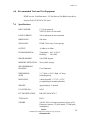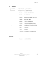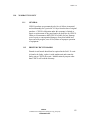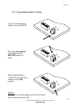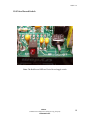
1
WPP-531-D2-ADA-VA-R-ST24VDC-ISSUE 4.0
SERVICE MANUAL
FOR
MODEL
WPP-531-D2-ADA-VA-R-ST24VDC
WEATHERPROOF TELEPHONE
SECOND NUMBER AUTO-DIAL
VOICE ANNOUNCEMENT
24VDC STROBE LIGHT
EQUIPPED WITH SPK-107UNVLr3 FIRMWARE
RED HOUSING & EMERGENCY BUTTON
Serving the Telephone Industry Since 1930
Communication Equipment
& Engineering Company
519 SW Park Street
Okeechobee, FL 34972
Voice: 863-357-0798
Fax: 863-357-0006
ISSUE 4.0
IMPORTANT INFORMATION
FOR
CUSTOMER
Please fill in before you continue.
The following information is necessary when calling CEECO for assistance.
MODEL NUMBER
MODEL:
WPP-531-D2-ADA-VA-R-ST24VDC
EQUIPPED WITH SPK107UNVLr3
FIRMWARE
SERIAL NUMBER
DATE MANUFACTURED
LOCATION INSTALLED
For us to better serve you, please have this information available when calling for
technical support.
CEECO
Communication Equipment & Engineering Company
519 SW Park Street
Okeechobee, FL 34972
(863) 357-0798 Voice
(863) 357-0006 Fax
CEECO
Communication Equipment & Engineering Company
PROPRIETARY
2
ISSUE 4.0
TABLE OF CONTENTS
SECTION
PAGE
1.0
INTRODUCTION.......................................................................................................................... 4
2.0
GENERAL DESCRIPTION ......................................................................................................... 4
GENERAL DESCRIPTION CONTINUED…............................................................................. 5
3.10
VOICE ANNOUNCEMENT......................................................................................................... 9
4.0
OPERATION ............................................................................................................................... 10
5.0
INSTALLATION NOTES AND ASSEMBLY INSTRUCTIONS ........................................... 11
6.0
RECOMMENDED TOOLS AND TEST EQUIPMENT.......................................................... 12
7.0
SPECIFICATIONS...................................................................................................................... 12
8.0
PARTS LIST ................................................................................................................................ 13
10.0
REPAIR AND RETURN INFORMATION ............................................................................. 14
11.0
WARRANTY POLICY ............................................................................................................... 15
12.0
PROGRAMMING JUMPERS SETTINGS............................................................................... 16
13.0
INSTALLING STROBE LIGHT................................................................................................ 17
14.0
INSTALLING MODULAR PROTECTION JACK (RJ-11).................................................... 18
15.0
VOICE RECORD SWITCH ....................................................................................................... 19
CEECO
Communication Equipment & Engineering Company
PROPRIETARY
3
ISSUE 4.0
1.0
Introduction
The practices in this manual provide installation and maintenance
information for the CEECO Model WPP 531-D2-ADA-VA-R-ST24VDC
Hands-free Weatherproof Telephone.
The information in this manual is subject to change without notification.
For information not included in this manual, please call or write:
CEECO
519 SW Park Street
Okeechobee, FL 34972
(863) 357-0798 Voice
2.0
General Description
2.1
The CEECO Model WPP-531-D2-ADA-VA-R-ST24VDC Hands-free
telephone is housed in a cast-aluminum weatherproof housing. Instead of
a hook switch and handset, a RED Emergency Call Button is utilized for
the automatic dialing of a preprogrammed telephone number(s). The
preprogrammed number(s) may be up to eleven digits. If an emergency
call is made with the Red Emergency Button, the Blue strobe light will
be activated. The call and the Strobe Light can only be terminated by
pressing the RED button to hang up, or by the receipt of a wink back from
the called party hanging up, or by way of the preprogrammed time out
feature.
2.2
The telephone also provides an optional second-number auto-dial feature
for the Red Emergency Button. This allows a second number to be
automatically dialed, when no answer is received on the first auto-dial
number. The phone can be programmed to select the number of
unanswered rings (1-9), after which it will automatically release the
second auto-dial number.
2.3
The telephone provides an optional voice announcement feature, which
allows a pre-recorded message (up to 10 sec.) to play when the receiving
party answers the call. This feature will play to both the near and far end.
CEECO
Communication Equipment & Engineering Company
PROPRIETARY
4
ISSUE 4.0
General Description Continued…
2.4
The microphone is muted during periods of dial tone eliminating the use
of hand held dialers.
2.5
Incoming calls may be allowed or blocked depending on the programming
and Jumper settings.
2.6
Programming is accomplished via a separately supplied DTMF keypad.
2.7
The telephone may be programmed to automatically disconnect a call after
a selected time period of 1-9 minutes.
2.8
The telephone may also be programmed to automatically dial a PBX or
other access number of up to eleven (11) digits in length.
2.9
The telephone is equipped with a 24VDC Blue Strobe Light.
CEECO
Communication Equipment & Engineering Company
PROPRIETARY
5
ISSUE 4.0
3.0
Programming
NOTE:
It is recommended that you ground yourself to prevent ESD
damage to the Printed Circuit Boards.
3.1
Connect the telephone to a working telephone line or a DTMF test set
before programming.
3.2
Move the mini-jumper (located on the Printed Circuit Board) to the
"ON" position, as depicted in section 12, page 16 of this manual.
3.3
Press the RED Emergency Button and wait for dial tone before
programming any digits. Programming will be accomplished by utilizing
the keypad on the rear if the panel telephone.
3.4
It is important to be slow and deliberate when pressing the keys of the
programming keypad. A missed or partial tone could result in improper
programming.
NOTE: Once the “#" (pound) key has been entered you may get an
operator recording or a fast busy, please disregard and continue
programming.
3.5
Utilize the programming keypad to enter: # 9 7
This will clear all field programmable memory.
3.6
Enter #00 followed by a series of ten (10) Digits as selected from the
options on the following page. By entering 0 thru 9 into each of the 10
digits, the phone is customized for the particular installation. A selection
for all ten Digits MUST be entered in order for the phone to operate
properly.
CEECO
Communication Equipment & Engineering Company
PROPRIETARY
6
ISSUE 4.0
Programming Continued…
Digit 1:
0 Always 0 for this model.
Digit 2:
1 Always 1 for this model.
Digit 3:
0 No Conversation Time-Out.
1-9 Minutes Conversation Time-Out. (the call will automatically be terminated after the
selected number of minutes).
Digit 4:
0 Always 0 for this model.
Digit 5:
0 Always 0 for this model.
Digit 6:
0 Disable Second Number Dialing and ADA feature.
1-9 Activate Second Number Dialing (number of rings before retry) and ADA feature.
Digit 7:
0 Always 0 for this model
Digit 8: (PBX Access – see section 3.9)
0 Do not dial PBX access number stored in Location #l8.
1 Dial PBX access number stored in Location #18.
Digit 9:
0 Always 0 for this model.
Digit 10:
0 No Wink Detect.
1-9 Wink Detect (l = 50ms incremental to 450ms, 5 = 250ms recommended).
•
Be sure to record your selections below for future reference:
#00
0 __ __ 0 0 __ 0 __ 0 __
1 2 3 4 5 6 7 8 9 10
CEECO
Communication Equipment & Engineering Company
PROPRIETARY
7
ISSUE 4.0
Programming Continued…
EXAMPLE:
Enter #00 0160000005
Phone will be set as follows:
DIGIT 1 -- ALWAYS 0
DIGIT 2 -- ALWAYS 1
DIGIT 3 -- 6 MINUTE TIME OUT FOR EMERGENCY CALLS
DIGIT 4 -- ALWAYS 0
DIGIT 5 -- ALWAYS 0
DIGIT 6 -- SECOND NUMBER DIAL DEACTIVATED
DIGIT 7 -- ALWAYS 0
DIGIT 8 -- DO NOT DIAL PBX NUMBER STORED IN LOCATION #18
DIGIT 9 -- ALWAYS 0
DIGIT 10 -- 250ms WINK
3.7
Enter #19 followed by the desired auto-dial number. When the phone
is in operation and the RED Emergency Button is pressed, this auto-dial
number will automatically dial out. This number may be up to eleven (11)
digits in length. To Program a Second Number auto-dial on the RED
Emergency Button, Enter # 0 1 followed by the desired number.
#19 ___ ___ ___ ___ ___ ___ ___ ___ ___ ___ ___
#01 ___ ___ ___ ___ ___ ___ ___ ___ ___ ___ ___
(location #01 Second Number Dial for the RED Button)
Example: Enter # 1 9 5 5 5 1 2 1 2. This will program the phone to
automatically dial the number 555-1212, whenever the RED Button is
pressed. Enter # 0 1 5 8 7 5 4 3 0. This will program the phone to
automatically dial number 587-5430 if number 555-1212 does not answer.
CEECO
Communication Equipment & Engineering Company
PROPRIETARY
8
ISSUE 4.0
Programming Continued…
3.8
If it is necessary for the telephone to automatically dial a PBX or other
access number, enter # 1 8 followed by the desired PBX access code or
number. When the Red Call Button is pressed, this number will
automatically dial out, followed by the auto-dial number. There will be
approximately a one (1) second pause between the dialing of the two
numbers. This number may be up to eleven (11) digits in length. If this is
not a desired feature, proceed to the next section 3.09.
Example: Enter # 1 8 9. This will program the phone to automatically
dial the number 9, pause approximately one (1) second, and automatically
dial the auto-dial number, whenever the RED Button is pressed.
#18 ___ ___ ___ ___ ___ ___ ___ ___ ___ ___ ___
3.09
Press the RED Button to hang up the phone and return the minijumper to the "OFF" position, as depicted in section 12.0, page 16 of this
manual.
3.10
Voice Announcement
•
To record the voice announcement, press the RED Button, and the
phone will dial the preprogrammed number in location #19. It may be
easier to use another working number to do this, other than 911. In
such a case, move the jumpers to enter the programming mode, press
the button, enter only #19, followed by the working number and then
hang up and move the jumpers back. Press the button and proceed.
When done with the last item in this section, follow this process again
to restore the emergency/911 number.
•
Ask the called party to put their telephone on HOLD or remain quiet
while you prepare to record the message.
•
Refer to the diagram on page 23 to locate the Voice Record Switch on
the printed circuit board. Toggle the record switch to the ON position.
The phone's LED will turn red.
•
Speak clearly and loudly into the microphone on the front of the
phone. The message can be up to ten (10) seconds in length.
•
When finished, toggle the record switch to the OFF position. The
LED will turn off.
CEECO
Communication Equipment & Engineering Company
PROPRIETARY
9
ISSUE 4.0
4.0
Operation
Action:
Connect the phone to the line.
Press the RED Emergency Button.
Reaction:
The LED will illuminate red, the blue strobe light will
begin to flash, and the preprogrammed number(s) will
automatically dial out. When the call is answered, the
Voice announcement should be heard at both ends of the
telephone line, provided a recording of 10 seconds or less
was prerecorded. A normal speakerphone conversation
should take place.
Action:
If the first programmed number did not answer, the second
programmed number for the RED button should
automatically dial out. The dialing for the two
programmed numbers should continue back and forth until
one of them is answered.
Reaction:
Once answered, the call should continue as normal.
Action:
When the call is finished, press the RED Button or wait
until the timeout reset occurs, or the wink detect reset
occurs.
Reaction:
The call is terminated and the LED will turn off.
NOTE: CEECO can not be responsible for the called party's response
regarding ADA features and compliance, and emergency response.
*****WARNING*****
A.
Never install telephone wiring during a lightning storm.
B.
Never install telephone jacks in wet locations unless the jack
is specifically designed for wet locations.
C.
Never touch uninsulated telephone wires or terminals unless
the telephone line has been disconnected at the network interface.
D.
Use caution when installing or modifying telephone lines.
CEECO
Communication Equipment & Engineering Company
PROPRIETARY
10
ISSUE 4.0
5.0
Installation Notes and Assembly Instructions
Using a 301-064 security tool (sold separately) loosen and remove the
security screws.
The security tool is for a standard 5/32" button head screw generally used
on the framework of the phone booths.
Separate the faceplate assembly from the weatherproof housing or
mounting by pulling the faceplate forward.
Run the inside station wire into the enclosure and terminate on the RJ1lC
terminal block inside as depicted on page 18, section 14 of this manual.
The CEECO-supplied modular jack MUST be used as it contains
necessary over-voltage protection.
The use of a gas tube station protector is recommended. The station
ground should not exceed 50 ohms. This is with regard to the C.O. or
PBX termination points.
Plug the modular line cord from the panel telephone/faceplate assembly
into the RJ11C terminal block.
If you have not programmed the Emergency number then it should be
entered now. See section 3.0.
Run the 24VDC wiring into the weatherproof housing and terminate as
depicted on page 17, section 13 of this manual.
NOTE: There should be no supply to this wiring until
installation is completed. All wiring should be accomplished
by a licensed professional and with regard to all applicable
laws, codes, ordinances, etc…
Dress the line cable and other wires away from the security screws and
seat the faceplate into the weatherproof housing or mounting.
Secure the cover assembly by tightening the security screws.
CEECO
Communication Equipment & Engineering Company
PROPRIETARY
11
ISSUE 4.0
6.0 Recommended Tools and Test Equipment
DTMF test set; Volt/Ohm meter; 3/8” Nut Driver; Flat Blade Screwdriver;
Security Tool (CEECO P/N 301-064)
7.0
Specifications
INPUT POWER:
C.O. Line powered
24VDC/0.44-0.10A for strobe
LOOP CURRENT:
35mA minimum 80 mA maximum
IMPEDANCE:
600 ohms
SIGNALING:
DTMF, 70ms tone, 50 ms spacing
OUTPUT:
-4.0dbm to -6.0dbm
ENVIRONMENTAL:
Temperature 0o C to 50o C
Humidity
20%-90%
PROGRAMMING:
Via DTMF keypad.
MEMORY RETENTION:
Non-volatile storage
WEATHERPROOF
HOUSING:
Cast Aluminum
DIMENSIONS:
(WPP)
9 ½” Wide x 12 5/8” High x 8” deep.
(including door).
MOUNTING:
4 holes spaced 8” x 5 7/8” x 13/32”
(or optional pole mounting bracket)
WEIGHT:
Approximately 13 pounds.
UL LISTED NO.:
6OF5
FCC REGISTRATION:
BW-88T7-68447-KX-T
TYPE JACK:
RJ11C
STROBE:
24VDC; 0.44-0.10 Amps operating current; 65-95
Flashes per minute; 2.2 joule output; 175,000 peak
candlepower.
CEECO
Communication Equipment & Engineering Company
PROPRIETARY
12
ISSUE 4.0
8.0
Parts List
QUANTITY
PART NUMBER
DESCRIPTION
4
9024
SECURITY SCREW
1
301-018
MODULAR LINE CORD
1
531-000
FACE PLATE
1
301-054
MODULAR CONNECTOR (RJ11)
1
700-008
KEYPAD CABLE
1
660-000
CEECO SPKR. BOARD
1
705-110
CONNECTORIZED KEYPAD
2
6020-B
MOMENTARY PANEL SWITCH
1
14024
SPEAKER
1
12017
RINGER
1
301-14144
24VDC BLUE STROBE LIGHT
Accessories:
1
301-064
SECURITY TOOL
CEECO
Communication Equipment & Engineering Company
PROPRIETARY
13
ISSUE 4.0
10.0
Repair and Return Information
10.1
WARRANTY REPAIR
Any device returned requiring warranty service, repair or credit
must be accompanied with a "Return Material Authorization"
(RMA) FORM. It must include: return shipping instructions,
original purchase order number and special marking instruction. A
description of the trouble observed must be attached to the
defective unit. This information must be inside the shipping
container.
10.2
DIRECT ALL INQUIRES TO:
CEECO
Repair Department
519 SW Park Street
Okeechobee, FL 34972
(863) 357-0798 Voice
(863) 357-0006 Fax
10.3 NON-WARRANTY REPAIR
CEECO will repair equipment out of warranty for a set charge plus
parts. The customer must pay the shipping costs both directions.
10.4 RETURN FOR CREDIT
Material may be returned for credit only with prior approval.
Material authorized for return is subject to a 20% restocking
charge based on the manufacturer’s list price. Return RMA must
be requested no later than 30 days after original shipment.
10.5 EXCHANGE POLICY
If a replacement unit is required it will be shipped in the most
expedient manner consistent with the urgency of the situation.
Please contact "customer service" for instructions regarding
exchange of modules or printed circuit boards.
CEECO
Communication Equipment & Engineering Company
PROPRIETARY
14
ISSUE 4.0
11.0
WARRANTY POLICY
11.1
GENERAL
CEECO products are guaranteed to be free of defects in material
and workmanship for a period of 365 days from the date of original
purchase. CEECO's obligation under this warranty is limited to
repair or replacement of any part found to be defective by CEECO.
Under no circumstances shall CEECO be liable for loss, damage,
cost of repair or consequential damages of any kind which have
been caused by neglect, acts of God, abuse or improper operation
of equipment.
11.2
PRINTED CIRCUIT BOARDS
Printed circuit boards should not be repaired in the field. If a unit
is found to be faulty, replace it with another unit and return the
faulty unit to CEECO for repair. Modifications by anyone other
than CEECO will void the warranty.
CEECO
Communication Equipment & Engineering Company
PROPRIETARY
15
ISSUE 4.0
12.0 Programming Jumpers Settings
Locate the mini jumpers
on the corner of the PCB.
ON
F
OF
Move the mini jumpers
to the ON position
BEFORE going offhook.
ON
F
OF
When programming is
completed, move the mini
jumpers to the OFF
position.
ON
F
OF
NOTE:
Do not leave the mini jumpers in the ON position;
this will decrease battery life.
CEECO
Communication Equipment & Engineering Company
PROPRIETARY
16
ISSUE 4.0
13.0 Installing Strobe Light
Connect +24VDC to terminal #2 as shown above.
Connect the White wire from the Blue Strobe Light to terminal #1 shown above.
Using the supplied yellow wire nut, securely twist -24VDC wire from your power
supply to the Black wire from the Blue Strobe Light.
CEECO
Communication Equipment & Engineering Company
PROPRIETARY
17
ISSUE 4.0
14.0 Installing Modular Protection Jack (RJ-11)
CEECO
Communication Equipment & Engineering Company
PROPRIETARY
18
ISSUE 4.0
15.0 Voice Record Switch
Note: The Red Record LED and Voice Record toggle switch
CEECO
Communication Equipment & Engineering Company
PROPRIETARY
19