1
Model 266
Photomultiplier Base
Operating and Service Manual
Printed in U.S.A.
ORTEC® Part No. 733120
Manual Revision B
1202
Advanced Measurement Technology, Inc.
a/k/a/ ORTEC®, a subsidiary of AMETEK®, Inc.
WARRANTY
ORTEC* warrants that the items will be delivered free from defects in material or workmanship. ORTEC makes
no other warranties, express or implied, and specifically NO WARRANTY OF MERCHANTABILITY OR
FITNESS FOR A PARTICULAR PURPOSE.
ORTEC’s exclusive liability is limited to repairing or replacing at ORTEC’s option, items found by ORTEC to
be defective in workmanship or materials within one year from the date of delivery. ORTEC’s liability on any
claim of any kind, including negligence, loss, or damages arising out of, connected with, or from the performance
or breach thereof, or from the manufacture, sale, delivery, resale, repair, or use of any item or services covered
by this agreement or purchase order, shall in no case exceed the price allocable to the item or service furnished
or any part thereof that gives rise to the claim. In the event ORTEC fails to manufacture or deliver items called
for in this agreement or purchase order, ORTEC’s exclusive liability and buyer’s exclusive remedy shall be release
of the buyer from the obligation to pay the purchase price. In no event shall ORTEC be liable for special or
consequential damages.
Quality Control
Before being approved for shipment, each ORTEC instrument must pass a stringent set of quality control tests
designed to expose any flaws in materials or workmanship. Permanent records of these tests are maintained for
use in warranty repair and as a source of statistical information for design improvements.
Repair Service
If it becomes necessary to return this instrument for repair, it is essential that Customer Services be contacted in
advance of its return so that a Return Authorization Number can be assigned to the unit. Also, ORTEC must be
informed, either in writing, by telephone [(865) 482-4411] or by facsimile transmission [(865) 483-2133], of the
nature of the fault of the instrument being returned and of the model, serial, and revision ("Rev" on rear panel)
numbers. Failure to do so may cause unnecessary delays in getting the unit repaired. The ORTEC standard
procedure requires that instruments returned for repair pass the same quality control tests that are used for
new-production instruments. Instruments that are returned should be packed so that they will withstand normal
transit handling and must be shipped PREPAID via Air Parcel Post or United Parcel Service to the designated
ORTEC repair center. The address label and the package should include the Return Authorization Number
assigned. Instruments being returned that are damaged in transit due to inadequate packing will be repaired at the
sender's expense, and it will be the sender's responsibility to make claim with the shipper. Instruments not in
warranty should follow the same procedure and ORTEC will provide a quotation.
Damage in Transit
Shipments should be examined immediately upon receipt for evidence of external or concealed damage. The carrier
making delivery should be notified immediately of any such damage, since the carrier is normally liable for damage
in shipment. Packing materials, waybills, and other such documentation should be preserved in order to establish
claims. After such notification to the carrier, please notify ORTEC of the circumstances so that assistance can be
provided in making damage claims and in providing replacement equipment, if necessary.
Copyright © 2002, Advanced Measurement Technology, Inc. All rights reserved.
*ORTEC® is a registered trademark of Advanced Measurement Technology, Inc. All other trademarks used
herein are the property of their respective owners.
iii
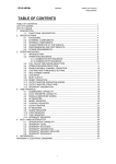
CONTENTS
WARRANTY . . . . . . . . . . . . . . . . . . . . . . . . . . . . . . . . . . . . . . . . . . . . . . . . . . . . . . . . . . . . . . . . . . . . . . . ii
SAFETY INSTRUCTIONS AND SYMBOLS . . . . . . . . . . . . . . . . . . . . . . . . . . . . . . . . . . . . . . . . . . . . . . . iv
SAFETY WARNINGS AND CLEANING INSTRUCTIONS . . . . . . . . . . . . . . . . . . . . . . . . . . . . . . . . . . . . . v
1. DESCRIPTION . . . . . . . . . . . . . . . . . . . . . . . . . . . . . . . . . . . . . . . . . . . . . . . . . . . . . . . . . . . . . . . . . . . 1
1.1. GENERAL . . . . . . . . . . . . . . . . . . . . . . . . . . . . . . . . . . . . . . . . . . . . . . . . . . . . . . . . . . . . . . . . 1
2. SPECIFICATIONS
............................................................... 1
3. INSTALLATION INSTRUCTIONS . . . . . . . . . . . . . . . . . . . . . . . . . . . . . . . . . . . . . . . . . . . . . . . . . . . .
3.1. DETECTOR MOUNTING . . . . . . . . . . . . . . . . . . . . . . . . . . . . . . . . . . . . . . . . . . . . . . . . . . . . .
3.2. INITIAL ADJUSTMENTS . . . . . . . . . . . . . . . . . . . . . . . . . . . . . . . . . . . . . . . . . . . . . . . . . . . . .
3.3. CONNECTING INTO A SYSTEM . . . . . . . . . . . . . . . . . . . . . . . . . . . . . . . . . . . . . . . . . . . . . . .
1
1
1
2
4. OPERATING INSTRUCTIONS . . . . . . . . . . . . . . . . . . . . . . . . . . . . . . . . . . . . . . . . . . . . . . . . . . . . . . .
4.1. TIMING WITH PHOTOMULTIPLIERS . . . . . . . . . . . . . . . . . . . . . . . . . . . . . . . . . . . . . . . . . . .
4.2. TIMING APPLICATIONS . . . . . . . . . . . . . . . . . . . . . . . . . . . . . . . . . . . . . . . . . . . . . . . . . . . . .
4.3. SCINTILLATION SPECTROSCOPY . . . . . . . . . . . . . . . . . . . . . . . . . . . . . . . . . . . . . . . . . . . . .
2
2
2
5
5. MAINTENANCE . . . . . . . . . . . . . . . . . . . . . . . . . . . . . . . . . . . . . . . . . . . . . . . . . . . . . . . . . . . . . . . . . . 5
iv
SAFETY INSTRUCTIONS AND SYMBOLS
This manual contains up to three levels of safety instructions that must be observed in order to avoid
personal injury and/or damage to equipment or other property. These are:
DANGER
Indicates a hazard that could result in death or serious bodily harm if the safety instruction
is not observed.
WARNING
Indicates a hazard that could result in bodily harm if the safety instruction is not observed.
CAUTION
Indicates a hazard that could result in property damage if the safety instruction is not
observed.
Please read all safety instructions carefully and make sure you understand them fully before attempting to
use this product.
In addition, the following symbol may appear on the product:
ATTENTION–Refer to Manual
DANGER–High Voltage
Please read all safety instructions carefully and make sure you understand them fully before attempting to
use this product.
v
SAFETY WARNINGS AND CLEANING INSTRUCTIONS
DANGER
Opening the cover of this instrument is likely to expose dangerous voltages. Disconnect the
instrument from all voltage sources while it is being opened.
WARNING Using this instrument in a manner not specified by the manufacturer may impair the
protection provided by the instrument.
Cleaning Instructions
To clean the instrument exterior:
! Unplug the instrument from the ac power supply.
! Remove loose dust on the outside of the instrument with a lint-free cloth.
! Remove remaining dirt with a lint-free cloth dampened in a general-purpose detergent and water
solution. Do not use abrasive cleaners.
CAUTION To prevent moisture inside of the instrument during external cleaning, use only enough liquid
to dampen the cloth or applicator.
!
Allow the instrument to dry completely before reconnecting it to the power source.
vi
1
ORTEC MODEL 266
PHOTOMULTIPLIER BASE
1. DESCRIPTION
1.1. GENERAL
The ORTEC 266 Photomultiplier Base is designed
to provide a voltage distribution to essentially all 10stage photomultiplier tubes that fit the standard 14pin tube socket. This unit provides output signals
capacitively coupled from the anode and the 10th
dynode for use in coincidence timing or linear pulse
height analysis. The access to both the last dynode
and the anode allows a selection of signal polarity
without the need of an inverting amplifier. Signal
quality is such that these outputs may feed 50
terminated coaxial cables or linear preamplifiers
S
such as the ORTEC 113 Scintillation Preamplifier.
Some of The photomultiplier tubes with which this
PM base is compatible are as follows:
RCA: 8053, 8054, 8055, 7326, 6655A, 6342A
Philips: XP-1000 to 1005, XP-1031 through 1033
EMI: 9656K, 9708K, and 9709K
CBS: 7817, 7818, 7819, and CL-1004 to 1012
Dumont: 6292, 6363, 6364
The 266 is also compatible with other tubes not
listed above. Compatibility may be inferred by
comparison with those listed.
2. SPECIFICATIONS
Note: All photomultiplier specifications are given by the manufacturer.
High Voltage Positive, 2.5 kV maximum.
Bleeder Resistance 1.5 M
S total.
Controls Focus Electrode Voltage Adjust available
externally.
S
Signals
Anode, negative, Z o -1.1 M ,
capacitively coupled; Dynode (10th), positive, Zo
-1.1 M , capacitively coupled.
S
Connectors BNC.
High Voltage Connector SHV.
3. INSTALLATION INSTRUCTIONS
3.1. DETECTOR MOUNTING
3.2. INITIAL ADJUSTMENTS
Normally with 10-stage photomultipliers the amount
of signal current pulled through the tube is small;
therefore it is quite practical to run positive high
voltage on the tube, i.e., run the cathode at ground
potential. This means that when the detector is
mounted to the photocathode, very little attention
need be paid to the probability of leakage currents
being created across the glass envelope, since the
voltage potential should be zero. In many cases
where the 266 is used, the detector will be mounted
to the photomultiplier in an integral package, When
this is the case, the photomultiplier tube can simply
be plugged into the 266 and a positive high voltage
of the desired value applied.
The only adjustment with this unit is that of the
focus electrode, which optimizes the photocathodefirst dynode geometry. Once the photomultiplier is
plugged into the socket and the tube detector
assembly is made light-tight, high voltage should be
applied in accordance with the specifications of the
particular tube involved and in line with the gain
desired from the photomultiplier tube. Then the
focus adjustment potentiometer should be adjusted
to that value which produces the maximum output
signal as monitored with an oscilloscope, either
directly or after a linear amplifier. Note: When
either the anode or dynode output is not being
utilized, it should be terminated in a low impedance,
e.g., 100- , terminator.
S
2
3.3. CONNECTING INTO A SYSTEM
Either the dynode or anode signal may be coupled
by way of an ORTEC 113 preamplifier into a linear
amplifier for pulse preparation when scintillation
spectrometry is to be performed. When a time
signal is desired, either the dynode or anode signal
may be utilized for this purpose. The output signal
should be transmitted over high quality coaxial
cable that is terminated at the receiving end into the
timing electronics; the latter will usually be some
type of fast amplifier and discriminator combination
such as the ORTEC 260, etc.
4. OPERATING INSTRUCTIONS
Once the steps outlined in Section 3 of this manual
are performed, the unit is ready for use. High
voltage may be applied and adjusted for the
appropriate gain associated with the specific
experiment. The gain will vary by a factor of -2 for
each high voltage change of 100 V.
Note: It is advisable to operate the high voltage
at the minimum practical value when high count
rates are to be experienced, since count rate
tolerance is a direct function of the
photomultiplier gain.
4. jitter and uncertainties of times of triggering of
the associated electronics.
The variation in the time of interaction can be
minimized by appropriate geometry and small
scintillators with a corresponding loss in efficiency
and average energy deposition.
For a complete discussion of timing with
photomultipliers the reader is referred to some of
the excellent literature available on the subject.1-4
4.2. TIMING APPLICATIONS
4.1. TIMING WITH PHOTOMULTIPLIERS
Timing with photomultipliers implies some type of
coincidence measurement. This measurement may
be performed with standard coincidence circuits
such as those of the pulse overlap type, which are
essentially single channel time analyzers, or with
time to pulse height converters, which are
differential or multichannel time analyzers.
The response of the coincidence system to I a
Prompt cascade always has a finite width that
comes from a variety of sources. The most
important of these are as follows:
1. variation of time of interaction of radiation with
the scintillator and the amount of energy deposited
therein,
2. finite decay time of light-emitting states in the
phosphor and variation of times of photon arrival at
the multiplier cathode,
3. variation of transit time of photoetectrons in the
photomultiplier due to different path lengths and to
variation of initial energy and angle of the
secondary electrons,
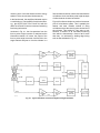
The various applications for the ORTEC 266 are
essentially limitless, but since the unit is designed
for timing is well as spectroscopy, two of the most
often used coincidence systems are discussed and
block diagrams given. From these two block
diagrams, other applications may be formulated by
extension.
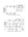
Typical Fast-Slow Coincidence System Using
Nal(TI) The block diagram of Fig. 4.1 outlines a
fast-slow coincidence system. The words "fast-slow"
mean that these are essentially two channels of
information retrieval operating in parallel. The fast
channel sets the ultimate resolving time of the
coincidence circuitry, and the slow channel selects
the pulse-height range to be accepted from each
detector. By means of a slower coincidence
requirement, the slow channel requirement is
combined with the fast coincidence requirement to
yield information having the criteria of the fast
1
A. Schwarzschild, NuoL tnstr. Methods 21,1 (1963).
G. Present et al., NucL Instr. Methods 31(l), 71 (1964).
3
E. Gatti and V. Svelto, Nucl. Instr. Methods 30, 213 (1964).
4
The Single-Photon Technique for Measuring Light
Intensity and Decay Characteristics, ORTEC Application Note
35 (1971).
2
3
resolving time of the fast channel and the energy
selection of the slow channel simultaneously.
In the fast channel, the amplifiers indicated may be
a combination of fast amplifier-fast discriminator,
e.g., the ORTEC 260 Time Pickoff Unit with the
403A Time Pickoff Control as a means of extracting
fast timing information.
As shown in Fig. 4.1, the time spectrum from the
time to pulse height converter is analyzed as the
information channel. Of course, the output of the
time to pulse height converter could be fed to the
single channel analyzer to form the ultimate in a
fast coincidence channel, which could then feed the
coincidence circuit and allow pulse height analysis
of either detector channel as desired.
Figure 4.2 outlines a simple conventional crossover
pick-off coincidence system. This is probably the
easiest and most versatile method of doing
coincidence where the resolving time desired is not
the ultimate. This method is very easy to use;
however, it results in a 2 coincidence resolving
time which is theoretically a factor of -12 worse
than may .be achieved by leading edge timing
such as was indicated in Fig. 4.1.
J
Fig. 4.1. Typical Fast-Slow Coincidence System Using Scintillators.
4
Fig. 4.2. Conventional Crossover Pickoff Coincidence System.
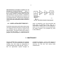
Fig. 4.3. Gamma-Gamma Coincidence System Using Ge(Li) Detector.
5
Gamma-Gamma Coincidence System for the
Germanium (Li-Drifted) Detector
Shown in
Fig. 4.3 is a block diagram of an experimental setup
that is quite versatile for studying decay schemes
and transitional levels by means of coincidence
between a lithium-drifted germanium detector and
a scintillation detector. With this block diagram the
experimenter may study either energy information
or time information associated with the coincidence
events.
4.3. SCINTILLATION SPECTROSCOPY
Scintillation spectroscopy implies the measurement
of energy by the direct conversion of energy to light
in a scintillator and the detection thereof by the
photomultiplier. The system to perform this function
is one of the most simple; i.e., it requires only the
phosphor, the photomultiplier, a base structure for
Fig. 4.4. Scintillation Spectroscopy System.
same, a preamplifier, and a linear amplifier with
some type of measuring device such as a
multichannel analyzer. Such a block diagram is
shown in Fig. 4.4. With this, one may study directly
the energy released in the phosphor by some
incident radiation.
5. MAINTENANCE
Since the ORTEC 266 is composed only of passive
components, very little maintenance is expected,
entailing only such things as replacement of
components that have failed with age. Table 6.1
lists the approximate dynode voltages for
comparative purposes. In such a case almost all
failures of the dynode string may be isolated by
removing the PM tube and making these
measurements.
6
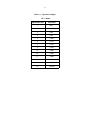
Table 6.1. Typical dc Voltages
HV = +2000V
PM SOCKET PIN
VOLTAGE
1
+330
2
+500
3
+660
4
+830
5
+1000
6
+1170
7
+1350
8
+1520
9
+1690
10
+1840
11
+2000
12
NC
13
0 - +330
14
Ground