1
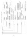
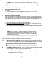
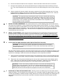
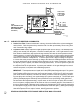
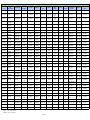
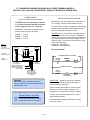
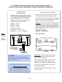
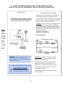
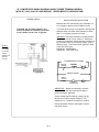
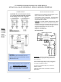
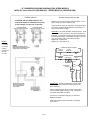
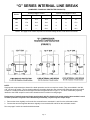
REVISED:
SUPERSEDES:
“G” SERIES
!! BEFORE A SUSPECT COMPRESSOR IS REMOVED, ALWAYS
CHECK LOCKED ROTOR PULL-DOWN VOLTAGE !!
SEE PAGE 4 FOR DETAILS
INSTALLATION AND SERVICE INSTRUCTIONS
AIR CONDITIONING/HEAT PUMP
COMPRESSORS
CAUTION: Bristol compressors are completely interchangeable with other manufacturers.
However, electrical specifications, tubing configurations, and wiring connections may vary.
Before installing and starting this compressor, you must review the wiring diagrams and
check for correct electrical components.
BRISTOL COMPRESSORS INTERNATIONAL, INC.
BRISTOL, VIRGINIA 24202
(276) 466-4121
FAX (276) 645-2423
Page 1
www.bristolcompressors.com
11/12
1/12
Index
Page
Cover Sheet ............................................................................................................................................................... 1
Index .......................................................................................................................................................................... 2
Compressor Model Number System .......................................................................................................................... 3
(Refer to cross-reference table on page 25 for H22G USA Service Models to Standard “G” compressors)
Before Condemning a Compressor that Fails to Start ............................................................................................... 4
Installation Procedures After Compressor has Been Verified as Faulty ............................................................... 4 - 9
Worst Case Condition Checks ................................................................................................................................... 8
How to Check Superheat ........................................................................................................................................... 9
Check Filter Driers for Contamination ........................................................................................................................ 9
Module Electrical Schematics and Other Information
Summary of Electronic Modules ................................................................................................................. 10
AE, 31AA, 41AA or INT 369R Protection Modules (Parallel Sensors)
Dual Power Terminal, Full and Part Winding Start Models ........................................................................ 11
AE, 31AA, 41AA or INT 369R Protection Modules (Parallel Sensors)
Dual Power Terminal (WYE-Delta) Models ................................................................................................ 12
AE, 31AA, 41AA or INT 369R Protection Modules (Parallel Sensors)
Single Power Terminal Models ................................................................................................................... 13
AE, 30AA, 40AA or INT 169R Protection Modules (Series Sensors)
Single Power Terminal Models ................................................................................................................... 14
AE, 31AA, 41AA or INT 369R Modules (Parallel Sensors)
Two-Speed Models ..................................................................................................................................... 15
AE, 30AA, 40AA or INT 169R Modules (Series Sensors)
Two-Speed Models ..................................................................................................................................... 16
“G” Series Internal Line Break Models ........................................................................................................ 17
Housing Configuration Comparison ............................................................................................................ 17
Replacing Module Protected Compressor with Line Break Compressor .............................................. 17-18
Wiring a Two-Speed “G” for Single-Speed Operation ................................................................................ 19
Parts and Accessories for “G” Series Compressors ................................................................................................ 20
Rotalock Adapters and Valve Part Numbers and Drawings .................................................................................... 21
Compressor Mounting Information .......................................................................................................................... 22
Compressor Housing Tilt Angle ............................................................................................................................... 22
Explanation of the European Pressure Equipment Directive (PED) ........................................................................ 22
Pressure-Temperature Relation Chart ................................................................................................................ 23-24
H22G Cross-Reference Table to H*NG, H*BG and H*5G Models .......................................................................... 25
WARNING: Cannot use ICM parallel motor protection modules, part numbers 241730 or 241731, with Kriwan
sensors (cold resistance of 30-100 ohms for parallel sensors) because the modules have “shorted sensor
protection” that does not allow operation below 500 ohms.
Page 2
Page 3
WARNING: The air conditioning unit is a pressurized system and hazards exist which
could result in personal injury. It is therefore required that the following steps for troubleshooting removal and installation of the hermetic compressor be performed by qualified
personnel only.
BEFORE CONDEMNING A COMPRESSOR THAT FAILS TO START
1.
Verify all the following components are OK:
A. Contactor
B. Winding resistance within manufacturer’s specification (assure compressor is cool to the touch)
C. Compressor not grounded via ohmmeter/Megger, etc.
D. Compressor power terminals are tight and secure
E. Check for hot spots in system wiring (wire insulation melted, connectors/insulators melted, etc.)
2.
Verify lock rotor pull-down voltage (LRPDV):
Always check LRPDV before removing the old or new replacement compressor. If the LRPDV reduces the supply
voltage to the compressor below the “guaranteed to start” voltage of the compressor (three-phase 230/208 LRPDV
is 187V), the power supply must be corrected before removing the compressor. Always check all three legs, T1 to
T2, T1 to T3, and T2 to T3. To perform this test on two-speed compressors, you should wire for single-speed operation as illustrated on page 19.
Procedure to check for LRPDV: (Warning: Make sure unit is properly grounded before proceeding!)
A. Connect a voltmeter to the T1 terminal and T2 terminal of the compressor.
B. Make sure the terminal cover and retainer is in place (see warning page 7) then apply power to the compressor. If motor protector trips, allow time for reset before continuing.
C. If the voltage at the compressor terminals does not pull down below the LRPDV and the compressor still does
not start, it is electrically or mechanically faulty.
D. Repeat A through C for voltage at T1-T3 and T2-T3.
INSTALLATION PROCEDURES AFTER COMPRESSOR HAS BEEN VERIFIED AS FAULTY:
WARNING: Never use oxygen to pressurize a refrigeration or air conditioning system.
Oxygen can explode on contact with oil and could cause personal injury. When using high
pressure gas such as nitrogen or CO2 for this purpose, be sure to use a regulator that can
control the pressure down to 1 psig.
The following instructions are general but include major points of consideration that will ensure proper installation and protect you from possible personal injury. Please use this as a checklist, taking each item in its order before proceeding to the
next. If more information is required, please call Bristol Compressors Service Department.
1.
VERIFY PROPER APPLICATION. Verify that the compressor being replaced and the Bristol compressor have
a like capacity for the refrigerant being used and that the voltage and frequency characteristics are the same.
Consult your wholesaler if you have any questions about proper compressor application.
WARNING: To avoid electrical shock, power to the compressor should remain off during
performance of steps 2 thru 14.
2.
DETERMINE CAUSE OF INITIAL FAILURE. In order to prevent a second failure, the cause of the original failure must be determined. Identify the cause and make the necessary repairs.
A.
BEFORE REMOVING THE FAULTY COMPRESSOR: Remove refrigerant charge using proper recovery/
reclaim procedures. Call 1-800-235-7882 for the name of the nearest Dupont authorized distributor, or 1800-631-8138 for Honeywell Chemical Representative or 1-800-275-5532 for Mexichem Representative
for information on refrigerant reclaim program.
Page 4
B.
Remove the electrical leads from the compressor. Note the terminal to which each wire is connected.
C.
During the next operation, the access ports should be open so that pressure does not build up in the system. Use a high temperature torch to sweat the suction line and the discharge line loose from the compressor.
D.
Assure excessive oil does not remain in the system, measure oil in the failed compressor and, if oil is low,
flush excess from system (or see step 15 as an alternative). Good indicators of excess oil are: violent vibration and/or high variable sound as the extra oil moves through the system.
CAUTION: The compressor may contain harmful acids ¾ be sure to handle with extreme
care using proper protection equipment. After confirming oil charge level, return oil to the
compressor and install suction and discharge rotalock caps. Copper tube fittings should be
brazed closed. This is needed to prevent further contamination of the compressor and to
prevent spillage from the compressor.
3.
MOUNT THE NEW COMPRESSOR. Do not remove dust cover or rubber shipping plugs until all other connections have been completed (i.e., filters installed and all tubing changes made per Steps 3, 4, 5 and 6). Compressor should not be open to the atmosphere for more than 15 minutes. Be sure to use the new mounting grommets
that were shipped with the compressor. If the mounting sleeves shipped with the compressor are used, the
mounting bolts will bottom out when tight. Use care not to over-compress the mounting grommets when the
mounting sleeves cannot be used.
4.
INSTALL FILTER DRIERS. Bristol Compressors recommends the use of adequately sized liquid and suction
line driers anytime a compressor is replaced. If the new compressor is used to replace a compressor with a
burned motor, the use of high acid neutralizing filter drier is recommended. For heat pumps, a suction filter
drier must be installed between the accumulator and the compressor suction inlet. In addition, a bidirectional heat pump liquid line drier or factory recommended driers must be installed. NOTE: ALWAYS
REMOVE OLD FILTER DRIERS.
5.
ATTACH SUCTION AND DISCHARGE LINES (FOR UNITS WITH ROTALOCKS).
WARNING: Do not remove the rotalock caps without first relieving the dry air charge in
the compressor by carefully loosening the 1/4” flare suction access port cap to allow slow
release of all pressure.
After all housing pressure is relieved, remove the rotalock caps from the suction and discharge line fittings on the
compressor. On rotalock fittings, be sure the Teflon fiber seal located on the face of the fittings are seated properly and are not damaged. Attach the suction and discharge line to the compressor as follows:
A.
Align the suction and discharge line with the fitting on the compressor to ensure a good seal when the lines
are tightened. In some cases, it may be necessary to modify the system tubing to ensure proper alignment.
B.
Tighten the nuts on the suction and discharge line until you detect metal-to-metal contact between the fittings. At this point, the Teflon fiber seal has been totally compressed. Tighten the nuts an additional 1/4
turn to ensure good contact and a proper seal. (See rotalock torque valves on page 21.)
CAUTION: A Teflon seal is factory installed on the face of the suction and discharge line
rotalock fitting of the compressor. Use care not to damage this seal while removing the
shipping plug or attaching the suction line. Also, be sure to check the shipping plug once it
has been removed to ensure that part of the plug did not remain in the compressor.
6.
BRAZE ON SUCTION AND DISCHARGE LINES. Carefully remove the rubber plugs from the suction and discharge line fittings. Flow an inert gas, such as nitrogen or CO2, through the system at approximately 1/4 to 1 psig
to reduce the possibility of oxidation inside the tubing. Braze on the suction and discharge lines following the recommendation listed below (if a process tube is provided, it should be brazed shut after the system has been
charged):
Page 5
COPPER TUBING:
If additional copper tubing is required, use only clean, dehydrated refrigeration grade
tubing with sealed ends.
BRAZING ALLOYS:
CAUTION: Do not use 95/5, 50/50 or 40/60 soft solder for brazing. Use Sil-Fos or
Phos Copper, or similar brazing alloys with high tensile strength on copper welds
only. Weld steel to copper only with silver brazing alloys.
BRAZING PROCEDURE: To ensure properly brazed joints, Bristol Compressors recommends that the following
steps be used:
a. Exercise extreme care when cutting and forming tubes to keep dirt, filings, and
other contaminants from entering the system.
b. Do not use excessive amounts of brazing alloy as some of the excess may penetrate the joint and enter the system.
c. If flux must be used, take necessary precautions to ensure that the flux does not
enter the system.
d. Use damp cloths or other heat absorbent material to ensure that the factory
brazed joints on the compressor do not become damaged. If damp cloths are
used, take care not to allow moisture to enter the system.
e. Do not overheat brazed joints as excess heat will cause formation of copper oxide on the inside wall of the tubing. Flow an inert gas through the system, as explained above.
7.
If the Bristol compressor is being used as a replacement for a semi-hermetic using an oil pressure switch, remove
the switch from the unit. The Bristol compressor requires no such switch.
8.
CHECK SYSTEM FOR LEAKS. After installation is complete, pressurize the system to 75 psig using nitrogen
and a few ounces of system refrigerant. Check for leaks using a halide torch, soap bubbles or an electronic halogen leak detector. When all connections test satisfactorily, release pressure using proper recovery procedures,
then proceed to next step.
CAUTION: Do not use the Bristol replacement compressor as an evacuation assist and
never apply voltage to a compressor while it is in a vacuum as damage could result to the
compressor.
9.
10.
EVACUATE THE SYSTEM. Use a vacuum pump designed for this purpose. Vacuum must be pulled on the discharge (high side) and suction (low side) of the system. Evacuate to 200 microns or lower.
CHARGE THE SYSTEM. When a vacuum of at least 200 microns is reached, close gauge valve, remove vacuum pump, and break the vacuum using system refrigerant vapor. Never dump liquid refrigerant into the compressor. Liquid can be used to break the vacuum if it is connected to the liquid line, not the discharge line.
Charge the system according to the manufacturer's specifications. Be sure to compensate the charge for the addition of the filter drier. The preferred superheat should be 18-20°F (10-11°C) at the compressor on a system
with a TXV, see Step 16.
WEIGHING in the system charge to the factory specification will help point out system faults that may
still exist.
11.
INSTRUCTIONS FOR CHANGING MOTOR PROTECTION MODULES IN BRISTOL “G” SERIES COMPRESSORS: (Refer to page 10 for module summary chart)
WARNING: Assure power is turned off; sensor terminals can be hot to ground!
A.
Compressors identified with a “P” or “R” in the ninth character of the model number and small (12”) diameter
housing
1.
Disconnect the two wires from the two-pin hermetic terminal in the compressor housing.
2.
Remove the module mounting screws and remove the module and connecting wires.
3.
Install the new module using the same mounting screws. Two sensor lead wires should be attached
Page 6
4.
B.
12.
to the designated module terminals per the appropriate wiring diagram in this booklet. The free ends
should be fitted onto the two hermetic terminals. Either wire on either terminal is OK.
Follow appropriate wiring diagram in this booklet for connections to unit power and control circuit.
Compressors identified with a “P” or “R” in the ninth character of the model number and large (14”) diameter
housing
1.
Before disconnecting the four sensor leads, please note the top left pin of the four-pin terminal is in
the “COMMON” pin.
2.
Disconnect the four-wire block connector from the four-pin hermetic terminal in the compressor housing.
3.
Remove the module mounting screws and remove the module and connecting wires.
4.
Install the new module using the same mounting screws. Make the sensor lead wire connections as
follows, depending on the particular module being installed: (a) If the module includes one black wire
and three orange wires, connect the black wire to the common terminal as determined in Step 1
above. Connect the other three orange wires to the three remaining pins in any order.
5.
Follow appropriate wiring diagram in this booklet for connections to unit power and control circuit.
All electrical components should be checked. If faulty, or signs of degradation are found, they should be replaced. Check all connections and terminals for tightness. Use only a new Bristol protection module when
using Bristol replacement compressors.
WARNING: Voltage should not be applied to the compressor with the terminal cover and retainer(s)
removed as personal injury could result.
13.
Check pages 11 thru 16, 18 and 19 for correct wiring diagram.
WARNING: Do not remove "C" sensor wire on AE or 31AA modules or "S1" sensor wire on AE or 30AA
modules. These terminals are internally connected to line voltage, can be "hot" to ground.
WARNING: Cannot use ICM parallel motor protection modules, part numbers 241730 or 241731, with
Kriwan sensors (cold resistance of 30-100 ohms for parallel sensors) because the modules have
“shorted sensor protection” that does not allow operation below 500 ohms.
VERY IMPORTANT: Before applying power to the compressor, be sure to perform a functional check of
the motor protection system. This can be done by wiring the provided module as shown with the appropriate schematic, leaving the power supply wires from the main contactor open ¾ NO POWER TO COMPRESSOR. Then apply control circuit power. Main contactor should pull-in (or energize), assuming all
other safeties are closed. Next, carefully remove module sensor wires from compressor (only one necessary unless block connector is used). TAKE CARE NOT TO SHORT LEAD AGAINST HOUSING.
The main contactor should immediately open. If this does not happen, thoroughly check control wiring
unit until this functional check is positive. Then complete the system wiring.
WARNING: Replacement compressor failure may result if you fail to check the total electrical system
against the equipment manufacturer’s service manual and the Bristol compressor wiring diagram before
start-up. Make sure the electrical characteristics of the Bristol replacement compressor are the same as
the original compressor.
14.
Bristol recommends a four-minute time delay on break in series with the contactor to prevent short cycling of the
compressor from possible defective or improper operation of controls.
15.
Confirm oil is in compressor sight glass by depressing Schrader. After approximately two hours running
time, depress Schrader again and check the sight glass to be sure there is adequate oil in the compressor. If oil
Page 7
level is not visible, add Shrieve Zerol 150T oil until the level reaches the approximate mid-point of sight glass. If
oil level is above sight glass, remove oil until level is approximately 1/8” below top of sight glass.
16.
WORST CASE CONDITION CHECKS.
HEAT PUMP
STEP 1: Operate system in the heating mode with outdoor fan disconnected.
STEP 2: Run system until the designed winter condition in your area is reached (may need to cover coil for this
test).
STEP 3: Check suction superheat 6" from compressor inlet.
STEP 4: Superheat should not drop below 5°F (3°K) (prefer no lower than 10°F [6°K]).
STEP 5: Sump temperature should always be 50°F (28°C) or higher above saturated suction temperature.
EXAMPLE: "R-22"
38 psig = 16°F (-9°C) = SATURATED SUCTION
+ 50°F (28°K) = MINIMUM TEMP. DIFFERENCE
66°F (19°C) = MINIMUM SUMP TEMPERATURE
COOLING MODE (HEAT PUMP):
STEP 1: Operate system in cooling mode with indoor fan disconnected and repeat steps 3, 4 and 5.
AIR-CONDITIONING ONLY UNITS
STEP 1: Operate system in the cooling mode with indoor fan disconnected and repeat steps 3, 4 and 5.
Page 8
HOW TO CHECK RETURN GAS SUPERHEAT
58°F
DIGITAL
THERMOMETER
(14°C)
TAKE SUCTION
TEMPERATURE
6” TO 12” FROM
COMPRESSOR
58°F (14°C)
- 38°F (- 3°C)
20°F (11°K)
NOTE:
FOR THE HARD TO GET
TO COMPRESSOR, TAKE
TEMPERATURES HERE
(AIR CONDITIONING
UNIT ONLY)
CONVERT SUCTION
PRESSURE TO
TEMPERATURE
65 PSIG = 38°F (3°C)
SUPERHEAT
17.
CHECK FILTER DRIER FOR CONTAMINATION.
A. Suction Line Filter: If internal contamination is heavy, the suction line filter drier may become clogged
and ineffective. Check the pressure drop across the filter drier after approximately 8 hours running time
and, if it exceeds 2 psig, replace.
B. Liquid Line Filter: Always replace the original equipment liquid line filter drier(s). If the OEM liquid line
drier(s) is not removed from the system, a restriction most likely will result. Just a slight restriction in this
filter will reduce the efficiency of the system. A large restriction will cause the suction pressure and discharge pressure to be reduced. This reduction in pressure will occur only with a properly charged system
(i.e., refrigerant weighed in to the OEM specifications). An overcharged system will increase pressures
when there is a restriction in the liquid line. The service person tends to add more charge to the system
to increase the suction pressure. Normally any charge added above the OEM specifications will increase
the suction pressure due to the discharge pressure increasing, but in the case of a restriction, charge can
be added to a point the system shuts down on the high pressure switch. The service person may not see
the higher discharge pressure if the service port is in the liquid line which is normally downstream from
the liquid line filter drier in split systems. A pressure port installed in the hot gas discharge line, just as it
exits the compressor, is required to see true discharge pressure.
IMPORTANT: The compressor has an internal relief valve (IPRV) that is designed to open if the system
is subjected to a high pressure situation. Example causes are: overcharged, air in system, restriction,
factory installed metering device screens not removed and cleaned, old liquid line filter left in the system,
poor airflow across the condenser, condenser fan failure, poor airflow across the evaporator in the heating mode (dirty return air filter(s)), poor system design (duct system undersized), etc. The IPRV will open
when the discharge pressure exceeds the suction pressure by more than 450 psi (smaller than 15-ton
products) or 400 psi (larger than 15-ton products). If the relief valve opens, a high velocity gas flow may
be heard inside the compressor housing. In some cases, the relief may open so quickly due to a restriction in the system, the high pressure will be difficult to observe on standard gauges. In most instances, if
the service person installs a discharge service gauge on the discharge line just as it exits the compressor,
the development of high pressure can be observed before the relief valve opens. Installing the discharge
service gauge on the liquid line outside the system may not detect a restriction. To reset the relief valve,
shut the compressor off for a couple of minutes, allowing pressures to equalize.
REVIEW ALL SEVENTEEN STEPS TO MAKE SURE NOTHING WAS OVERLOOKED.
Page 9
Summary of Electronic Modules
Bristol
PN
Replace
with
Bristol PN
Vendor P/N
Supply
Voltage
Output
Sensors*
Rtrip
(W)
Reset
Delay
After
Break
LVCO
Short
Sensor
241073
None
10AA307
24
Voltage
Series
25K-35K
Auto
No
No
Yes
241283
None
10AA309
24
Voltage
Series
25K-35K
Manual
Yes
(lock
out)
No
241317
None
15AA1500A
24
Control
Parallel
10K-18K
Manual
Yes
(lock
out)
241359
241731 or
241744
15AA1000A
24
Control
Parallel
10K-18K
Auto
241373
241732 or
241742
15AA1106A
24
Control
Series
26K-34K
241374
241733 or
241743
15AA1607B
120
Control
Series
241375
241734 or
241743
15AA1607C
208/230
Control
241376
241732 or
241742
MP50-9401
24
241377
241733 or
241743
MP50-8601
241378
241734 or
241743
241379
248XXX
Schematic
Decals
Screw
Connector
Wires
obsolete
201125
obsolete
Yes
obsolete
201125
obsolete
No
Yes
obsolete
201126
241353
No
No
Yes
obsolete
201126
241353
Auto
Yes
No
Yes
obsolete
201126
651043
26K-34K
Auto
Yes
Yes
Yes
obsolete
201126
651043
Series
26K-34K
Auto
Yes
Yes
Yes
obsolete
201126
651043
Control
Series
26K-34K
Auto
Yes
No
Yes
obsolete
201126
651043
120
Control
Series
26K-34K
Auto
Yes
Yes
Yes
obsolete
201126
651043
MP50-8801
208/230
Control
Series
26K-34K
Auto
Yes
Yes
Yes
obsolete
201126
651043
241731 or
241744
15AA1105A
24
Control
Parallel
10K-16K
Auto
Yes
No
Yes
obsolete
201126
241353
241380
241745
15AA1606B
120
Control
Parallel
10K-16K
Auto
Yes
Yes
Yes
obsolete
201126
241353
241381
241745
15AA1606C
208/230
Control
Parallel
10K-16K
Auto
Yes
Yes
Yes
obsolete
201126
241353
241382
241731 or
241744
MP50-9201
24
Control
Parallel
10K-16K
Auto
Yes
No
Yes
obsolete
201126
241353
241383
241745
MP50-8001
120
Control
Parallel
10K-16K
Auto
Yes
Yes
Yes
obsolete
201126
241353
241384
241745
MP50-8201
208/230
Control
Parallel
10K-16K
Auto
Yes
Yes
Yes
obsolete
201126
241353
241559
241743
15AA1706C
208/230
Control
Parallel
10K-16K
Auto
Yes
Yes
Yes
obsolete
201126
241353
241560
241734 or
241743
15AA1707C
208/230
Control
Series
26K-34K
Auto
Yes
Yes
Yes
obsolete
201126
651043
241679
241731
31AA1105A
24
Control
Parallel
10K-16K
Auto
Yes
Yes
No
053,508,509,
510
201126
241353
241680
241745
31AA1606E
120&208/
230
Control
Parallel
10K-16K
Auto
Yes
Yes
No
051,052
201126
241353
241696
241732
30AA200A
24
Control
Series
26K-34K
Auto
Yes
Yes
No
053,508,509,
510
201126
651043
241697
241733 or
241743
30AA300B
120
Control
Series
26K-34K
Auto
Yes
Yes
No
051,052
201126
651043
241698
241734 or
241743
30AA300C
208/230
Control
Series
26K-34K
Auto
Yes
Yes
No
051,052
201126
651043
241730
241745
AE7114
120&208/
230
Control
Parallel
10K-16K
Auto
Yes
Yes
Yes
obsolete
201126
241353
241731
241770
AE7113
24
Control
Parallel
10K-16K
Auto
Yes
Yes
Yes
053,508,509,
510
201126
241353
241732
241772
AE7110
24
Control
Series
26K-34K
Auto
Yes
Yes
No
051,052
201126
651043
241733
241774
AE7111
120
Control
Series
26K-34K
Auto
Yes
Yes
No
051,052
201126
651043
241734
241774
AE7112
208/230
Control
Series
26K-34K
Auto
Yes
Yes
No
051,052
201126
651043
241744
241770
41AA1105A
24
Control
Parallel
10K-16K
Auto
Yes
Yes
No
obsolete
201126
241353
41AA1606E
120&208/
240
Control
Parallel
10K-16K
Auto
Yes
Yes
No
511,512,513,
514
201126
241353
241745
241771
241770
INT 369 R
24
Control
Parallel
10K-16K
Auto
Yes
Yes
No
511,512,513
201126
241353
241771
INT 369 R
120 & 240
Control
Parallel
10K-16K
Auto
Yes
Yes
No
511,512,513
201126
241353
241772
INT 169 R
24
Control
Series
26K-34K
Auto
Yes
Yes
No
052
201126
651043
241774
INT 169 R
120 & 240
Control
Series
26K-34K
Auto
Yes
Yes
No
052
201126
651043
*Series – 7 1/2, 8 1/2, 10 ton
Parallel – 15, 17, 20, 24 ton
Page 10
“G” COMPRESSOR WIRING DIAGRAM (DUAL POWER TERMINAL MODELS)
(WITH AE, 31AA, 41AA OR 369R MODULE) - PARALLEL MODULE (4 SENSOR PINS)
POWER CIRCUIT
(Full and Part-Winding Start Models)
CAUTION: AE and 31AA module common
(“C”) sensor terminal internally connected
to line voltage, can be “hot” to ground.
WARNING: Compressor terminals must be
wired in phase for proper operation.
POWER
TERMINAL
T1
T2
T3
Modules have a 4 minute delay upon interruption of
L1-L2 supply or after any fault condition occurs.
To prevent short cycling of compressor, wire high/low
pressure switch and other safety switches in series
with L1 or L2 power terminal on module.
WARNING: Turn power off before checking sensors.
Allow unit to cool for 1-hour minimum. Disconnect
module from terminals. Check sensors resistance using ohmmeter with 6-volt maximum supply. Cold resistance range: From common pin (top left) to each
of the other three pins.
Supplier #1: 30-100 ohms
Supplier #2: 500-2500 ohms
PHASE 1 - T1 & T7
PHASE 2 - T2 & T8
PHASE 3 - T3 & T9
MODELS:
H**G204FR
H**G244FR
H**G294FR
(Part Winding Start)
MOTOR PROTECTION SYSTEM
PROTECTION
TERMINAL
POWER
TERMINAL
T7
T8
T9
See caution below!
BLACK
H**G204DP
(Full Winding Start)
ORANGE
L1-L2 MODULE SUPPLY VOLTAGE
S1 S2 S3 C
Voltages:
230/208 3-PH
HI LO
TO T1, T3, T2
OF CONTACTOR
HIGH/LOW
PRESSURE
L1 L2 M2 M1
SAFETY
PROTECTION
L1
L2
MODULE
TO T7, T9, T8
OF CONTACTOR
MODULE SUPPLY VOLTAGE
(SEE MODULE SUMMARY ON
PAGE 10 FOR APPLICABLE
PART NUMBERS)
CONTROL VOLTAGE
MODULE
CONTACTS
TO CONTROL CIRCUIT
(M1-M2 CONTROL TO
BE PLACED IN SERIES
WITH CONTACTOR COIL)
2.5 AMPS MAX
M
M1
CAUTION:
ICM modules (part numbers 241730 and
241731) cannot be used with Kriwan sensors
(30-100 ohms, cold).
M2
TIME
DELAY
COMPRESSOR
CONTACTOR COIL
IMPORTANT: Bristol recommends a 4-minute
delay on break anti-short cycling time delay to
prevent contactor chattering.
Control voltage (thru M1-M2 on module) can be
different from module supply voltage (L1-L2).
Voltage to L1-L2 must be as marked on module.
HI-LO CONNECTIONS APPLY ONLY TO AE OR 31AA
“HI” and “LO” connections apply only on 120V
and 208/240V modules.
MODULE SUPPLY VOLTAGE
24V - No additional wiring
120V - Jumper terminal LO to L2 terminal
230V - Jumper terminal HI to L2 terminal
Crankcase heater must be connected to continuous power source.
Page 11
“G” COMPRESSOR WIRING DIAGRAM (DUAL POWER TERMINAL MODELS)
(WITH AE, 31AA, 41AA OR 369R MODULE) - PARALLEL MODULE (4 SENSOR PINS)
POWER CIRCUIT
(Wye-Delta Models)
MOTOR PROTECTION SYSTEM
CAUTION: AE and 31AA module common
(“C”) sensor terminal internally connected
to line voltage, can be “hot” to ground.
WARNING: Compressor terminals must be
wired in phase for proper operation.
Wye-Delta Connection:
Run (Delta) - 1 & 6, 2 & 4, 3 & 5
Start (Wye) - 1, 2, 3, (4, 5, 6 together)
Voltages:
230/208 3-PH
460 3-PH
To prevent short cycling of compressor, wire high/low
pressure switch and other safety switches in series
with L1 or L2 power terminal on module.
WARNING: Turn power off before checking sensors.
Allow unit to cool for 1-hour minimum. Disconnect
module from terminals. Check sensors resistance using ohmmeter with 6-volt maximum supply. Cold resistance range: From common pin (top left) to each
of the other three pins.
Supplier #1: 30-100 ohms
Supplier #2: 500-2500 ohms
PHASE 1 - T1 & T6
PHASE 2 - T2 & T4
PHASE 3 - T3 & T5
MODELS:
H**G204LP
H**G244LP
H**G294LP
Modules have a 4 minute delay upon interruption of
L1-L2 supply or after any fault condition occurs.
See caution below!
POWER
TERMINAL
T1
T2
T3
PROTECTION
TERMINAL
POWER
TERMINAL
T6
T4
T5
L1-L2 MODULE SUPPLY VOLTAGE
BLACK
HIGH/LOW
PRESSURE
ORANGE
SAFETY
PROTECTION
HI LO
TO T1, T3, T2
OF CONTACTOR
L1
L2
MODULE
S1 S2 S3 C
L1 L2 M2 M1
CONTROL VOLTAGE
TO T6, T5, T4
OF CONTACTOR
MODULE SUPPLY VOLTAGE
(SEE MODULE SUMMARY ON
PAGE 10 FOR APPLICABLE
PART NUMBERS)
MODULE
CONTACTS
M
M1
TO CONTROL CIRCUIT
(M1-M2 CONTROL TO
BE PLACED IN SERIES
WITH CONTACTOR COIL)
2.5 AMPS MAX
CAUTION:
ICM modules (part numbers 241730 and
241731) cannot be used with Kriwan sensors
(30-100 ohms, cold).
HI-LO CONNECTIONS APPLY ONLY TO AE OR 31AA
MODULE SUPPLY VOLTAGE
24V - No additional wiring
120V - Jumper terminal LO to L2 terminal
230V - Jumper terminal HI to L2 terminal
M2
TIME
DELAY
COMPRESSOR
CONTACTOR COIL
IMPORTANT: Bristol recommends a 4-minute
delay on break anti-short cycling time delay to
prevent contactor chattering.
Control voltage (thru M1-M2 on module) can be
different from module supply voltage (L1-L2).
Voltage to L1-L2 must be as marked on module.
“HI” and “LO” connections apply only on 120V
and 208/240V modules.
Crankcase heater must be connected to continuous power source.
Page 12
“G” COMPRESSOR WIRING DIAGRAM (SINGLE POWER TERMINAL MODELS)
(WITH AE, 31AA, 41AA OR 369R MODULE) - PARALLEL MODULE (4 SENSOR PINS)
POWER CIRCUIT
MOTOR PROTECTION SYSTEM
Modules have a 4 minute delay upon interruption of
L1-L2 supply or after any fault condition occurs.
CAUTION: AE and 31AA module common
(“C”) sensor terminal internally connected
to line voltage, can be “hot” to ground.
To prevent short cycling of compressor, wire high/low
pressure switch and other safety switches in series
with L1 or L2 power terminal on module.
WARNING: Turn power off before checking sensors.
Allow unit to cool for 1-hour minimum. Disconnect
module from terminals. Check sensors resistance using ohmmeter with 6-volt maximum supply. Cold resistance range: From common pin (top left) to each
of the other three pins.
Supplier #1: 30-100 ohms
Supplier #2: 500-2500 ohms
MODELS:
H*2G184DP
Voltages:
230/208 3-PH
See caution below!
H**G184DP
H**G204DR
H**G244DR
H**G294DP
L1-L2 MODULE SUPPLY VOLTAGE
Voltages:
460 3-PH
575 3-PH
HIGH/LOW
PRESSURE
SAFETY
PROTECTION
L1
L2
MODULE
H**G204DR
H**G244DR
CONTROL VOLTAGE
Voltages:
380 3-PH
MODULE
CONTACTS
M
M1
CAUTION:
ICM modules (part numbers 241730 and
241731) cannot be used with Kriwan sensors
(30-100 ohms, cold).
M2
TIME
DELAY
COMPRESSOR
CONTACTOR COIL
IMPORTANT: Bristol recommends a 4-minute
delay on break anti-short cycling time delay to
prevent contactor chattering.
Control voltage (thru M1-M2 on module) can be
different from module supply voltage (L1-L2).
Voltage to L1-L2 must be as marked on module.
HI-LO CONNECTIONS APPLY ONLY TO AE OR 31AA
“HI” and “LO” connections apply only on 120V
and 208/240V modules.
MODULE SUPPLY VOLTAGE
24V - No additional wiring
120V - Jumper terminal LO to L2 terminal
230V - Jumper terminal HI to L2 terminal
Crankcase heater must be connected to continuous power source.
Page 13
“G” COMPRESSOR WIRING DIAGRAM (SINGLE POWER TERMINAL MODELS)
(WITH AE, 30AA, 40AA OR 169R MODULE) - SERIES MODULE (2 SENSOR PINS)
POWER CIRCUIT
MOTOR PROTECTION SYSTEM
Modules have a 4 minute delay upon interruption of
L1-L2 supply or after any fault condition occurs.
CAUTION: AE and 30AA module (“S1”)
sensor terminals are internally connected
to line voltage, can be “hot” to ground.
To prevent short cycling of compressor, wire high/low
pressure switch and other safety switches in series
with L1 or L2 power terminal on module.
WARNING: Turn power off before checking sensors.
Allow unit to cool for 1-hour minimum. Disconnect
module from terminals. Check sensors resistance using ohmmeter with 6-volt maximum supply. Cold resistance range: From common pin (top left) to each
of the other three pins.
Supplier #1: 90-300 ohms
Supplier #2: 1500-7500 ohms
MODELS:
H**G094DP
H**G104DR
H**G124DP
Voltages:
230/208 3-PH
460 3-PH
575 3-PH
L1-L2 MODULE SUPPLY VOLTAGE
HIGH/LOW
PRESSURE
SAFETY
PROTECTION
L1
L2
MODULE
CONTROL VOLTAGE
MODULE
CONTACTS
M
M1
M2
TIME
DELAY
COMPRESSOR
CONTACTOR COIL
IMPORTANT: Bristol recommends a 4-minute
delay on break anti-short cycling time delay to
prevent contactor chattering.
Control voltage (thru M1-M2 on module) can be
different from module supply voltage (L1-L2).
Voltage to L1-L2 must be as marked on module.
Crankcase heater must be connected to continuous power source.
Page 14
“G” COMPRESSOR WIRING DIAGRAM (TWO SPEED MODELS)
(WITH AE, 31AA, 41AA OR 369R MODULE) - PARALLEL MODULE (4 SENSOR PINS)
MOTOR PROTECTION SYSTEM
POWER CIRCUIT
CAUTION: AE and 31AA module common
(“C”) sensor terminal internally connected
to line voltage, can be “hot” to ground.
Modules have a 4 minute delay upon interruption of L1-L2
supply or after any fault condition occurs.
To prevent short cycling of compressor, wire high/low pressure switch and other safety switches in series with L1 or
L2 power terminal on module.
WARNING: Turn power off before checking sensors. Allow
unit to cool for 1-hour minimum. Disconnect module from
terminals. Check sensors resistance using ohmmeter with
6-volt maximum supply. Cold resistance range: From common pin (top left) to each of the other three pins.
Supplier #1: 30-100 ohms
Supplier #2: 500-2500 ohms
MODELS:
H**G144GP
H**G184GP
H**G204GP
H**G244GP
See caution below!
L1-L2 MODULE SUPPLY VOLTAGE
HIGH/LOW
PRESSURE
Voltages:
230/208 3-PH
460 3-PH
575 3-PH
SAFETY
PROTECTION
L1
L2
MODULE
CONTROL VOLTAGE
MODULE
CONTACTS
COOLING RELAY
1
M1
M2
CS AUX
2
3
CF AUX
TIME
DELAY
CT AUX
4 MINUTE DELAY
ON BREAK
TIME
DELAY
CS
CF
CT
CAUTION:
ICM modules (part numbers 241730 and
241731) cannot be used with Kriwan sensors
(30-100 ohms, cold).
IMPORTANT: Bristol recommends a 4-minute delay
on break anti-short cycling time delay to prevent contactor chattering.
HI-LO CONNECTIONS APPLY ONLY TO AE OR 31AA
Control voltage (thru M1-M2 on module) can be different from module supply voltage (L1-L2). Voltage to L1L2 must be as marked on module.
MODULE SUPPLY VOLTAGE
24V - No additional wiring
120V - Jumper terminal LO to L2 terminal
230V - Jumper terminal HI to L2 terminal
“HI” and “LO” connections apply only on 120V and
208/240V modules.
Crankcase heater must be connected to continuous
power source.
Page 15
“G” COMPRESSOR WIRING DIAGRAM (TWO SPEED MODELS)
(WITH AE, 30AA, 40AA OR 169R MODULE) - SERIES MODULE (2 SENSOR PINS)
MOTOR PROTECTION SYSTEM
POWER CIRCUIT
CAUTION: AE and 30AA module (“S1”)
sensor terminals are internally connected
to line voltage, can be “hot” to ground.
Modules have a 4 minute delay upon interruption of L1-L2
supply or after any fault condition occurs.
To prevent short cycling of compressor, wire high/low pressure switch and other safety switches in series with L1 or
L2 power terminal on module.
WARNING: Turn power off before checking sensors. Allow
unit to cool for 1-hour minimum. Disconnect module from
terminals. Check sensors resistance using ohmmeter with
6-volt maximum supply. Cold resistance range: From common pin (top left) to each of the other three pins.
Supplier #1: 90-300 ohms
Supplier #2: 1500-7500 ohms
MODELS:
H**G094GP
H**G104GP
H**G124GP
L1-L2 MODULE SUPPLY VOLTAGE
Voltages:
230/208 3-PH
460 3-PH
575 3-PH
HIGH/LOW
PRESSURE
SAFETY
PROTECTION
L1
L2
MODULE
CONTROL VOLTAGE
MODULE
CONTACTS
COOLING RELAY
1
M1
M2
CS AUX
2
3
CF AUX
TIME
DELAY
CT AUX
4 MINUTE DELAY
ON BREAK
TIME
DELAY
CS
CF
CT
IMPORTANT: Bristol recommends a 4-minute delay
on break anti-short cycling time delay to prevent contactor chattering.
Control voltage (thru M1-M2 on module) can be different from module supply voltage (L1-L2). Voltage to L1L2 must be as marked on module.
“HI” and “LO” connections apply only on 120V and
208/240V modules.
Crankcase heater must be connected to continuous
power source.
Page 16
“G” SERIES INTERNAL LINE BREAK
(COMPARED TO MODULE PROTECTED PRODUCTS)
Suction Tube Height in Inches
Housing Height in Inches
Models
H*NG
H*BG
H*5G
H*NG
H*BG
H*5G
094
17.1
17.6
18.4
9
9
16
104
17.9
18.4
19.6
9
9
17.2
124
17.9
18.4
20.4
9
9
18
144
—-
—-
20.6
—-
—-
18.2
NOTE: See page 25 for models equivalent to the listed vintage H*NG, H*BG and H*5G models.
NOTE:
Single speed compressors have internal line break protection and do not require a module. They are available in the 094,
104, 124 and 144 models. The line break models are physically identical to the vintage H*NG solid-state protector models
except for a smaller terminal box and a slight increase in height as shown in Figure 1. The H*5G models are physically
identical to the H*BG except for suction tube location and an increase in housing height.
Replacement of module-protected single speed models with line break single speed models (when module is used
as motor protection only and is not controlled by thermostat), requires only two simple steps:
1. Remove the wires originally run from the line or transformer to terminals L1 and L2 on the solid state module.
2. Connect the two wires together that were originally run to terminals M1 and M2 on the solid state module.
See next page if module is controlled with thermostat.
Page 17
REPLACING MODULE PROTECTED COMPRESSORS WITH INTERNAL LINE
BREAK PROTECTED COMPRESSORS WHERE THE SYSTEM THERMOSTAT IS
USED TO CONTROL THE MODULE
MODULE PROTECTED COMPRESSORS
LINE BREAK PROTECTED COMPRESSORS
“G” COMPRESSOR - WIRING DIAGRAM
(Single Power Terminal Models with Series Sensor Module Protection)
LINE BREAK PROTECTED
MODULE PROTECTED
Page 18
WIRING A TWO-SPEED “G” FOR SINGLE-SPEED OPERATION
HIGH SPEED
LOW SPEED
L1
L2
L3
L1
L2
L3
CS
CF
NO CONNECTION
ON LOW SPEED
T1
T2
T3
T4
T5
T1
T6
T2
T3
Page 19
T4
T5
T6
PARTS AND ACCESSORIES
FOR “G” SERIES COMPRESSORS
PART NUMBER
DESCRIPTION
MODEL
250507 (344029)*
Discharge Service Valve 7/8”
(094-144)
250508 (344030)*
Suction Service Valve 1 1/8”
(094-124)
250509 (344031)*
Discharge Sweat Adapter 7/8”
(094-144)
250510 (344032)*
Suction Sweat Adapter 1 1/8”
(094-124)
250511
Discharge Seal
(094-294)
250512
Suction Seal
(094-294)
250527 (344035)*
Discharge Service Valve 1 1/8”
(184-294)
250525 (344033)*
Suction Service Valve 1 3/8”
(144)
250526 (344034)*
Suction Service Valve 1 5/8”
(184-294)
250530 (344037)*
Discharge Sweat Adapter 3/4” - 90°
(094-144)
250533 (344038)*
Suction Sweat Adapter 1 3/8” - 90°
(144)
250534 (344039)*
Discharge Adapter 1 1/8”
(184-294)
250529 (344036)*
Suction Adapter 1 3/8”
(144)
309008
Mounting Parts (Set 236203 Grommet Sleeve 236400)
(094-124)
309009
Mounting Parts (Set 236205 Grommet Sleeve 226260)
(144-294)
241711
Crankcase Heater 115V
(094-124)
241712
Crankcase Heater 230V
(094-124)
241713
Crankcase Heater 460V
(094-124)
241714
Crankcase Heater 575V
(094-124)
241703
Crankcase Heater 115V
(144)
241705
Crankcase Heater 460V
(144)
241708
Crankcase Heater 115V
(184-294)
241707
Crankcase Heater 230V
(184-294)
241706
Crankcase Heater 460V
(184-294)
241710
Crankcase Heater 575V
(184-294)
241730
Module 115/230V (Replaces 241380, 241381 and 241680)
(184-294)
241731
Module 24V (Replaces 241379 and 241679)
(184-294)
241732
Module 24V (Replaces 241373 and 241696)
(094-124)
241733
Module 115V (Replaces 241374 and 241697)
(094-124)
241734
Module 230V (Replaces 241375 and 241698)
(094-124)
241744
Module 24V (Replaces 241379, 241679 and 241731)
(184-294)
241745
Module 115/230V (Replaces 241380, 241381, 241680 and 241730)
(184-294)
241770
Module 24V (Replaces 241379, 241679, 241731 and 241744)
(184-294)
241771
Module 120/240V (Replaces 241380, 241381, 241680, 241730 and
241745)
(184-294)
241772
Module 24V (Replaces 241373, 241696 and 241732)
(094-124)
241774
Module 120/240V (Replaces 241374, 241375, 241697, 241698,
241733 and 241734
(094-124)
*Note: (344_ _ _) part number includes Teflon seal
Page 20
“G” SERIES ROTALOCK ADAPTER INFORMATION
SUCTION ADAPTERS
D
SUCTION SEAL
B
A
A
C
A
C
C
C
D
B
B
2505 29
2505 10
E
SU CTION
VALVE
B
2 5051 2
A
A
25 0533
250 508
250 525
250 526
DISCHARGE ADAPTERS
D
B
A
C
DISCHAR GE SEAL
C
A
D
C
B
A
2 505 34
250 509
E
DISCHARGE
VALVE
C
B
A
2 5051 1
B
25 0530
A
2 5050 7
2 5052 7
BRISTOL PART
NO.
250508 (344030)*
DESCRIPTION
Suction Valve
A
B
C
D
E
1 1/8
3
7 3/16
2 1/2
1 3/4-12 UNF
For 1 1/4”-12”
250511
Discharge Seal
1
250512
Suction Seal
1 1/2
250525 (344033)*
Suction Valve
1 3/8
3 5/16
7 3/16
2 1/2
1 3/4-12 UNF
250526 (344034)*
Suction Valve
1 5/8
3 1/2
7 3/16
2 1/2
1 3/4-12 UNF
250529 (344036)*
Suction Adapter Straight
1 3/8
2 1/2
1 3/4-12 UNF
250510 (344032)*
Suction Adapter Straight
1 1/8
2 3/16
1 3/4-12 UNF
250533 (344038)*
Suction Adapter 90°
1 3/8
2 3/16
1 3/4-12 UNF
2 3/8
250507 (344029)*
Discharge Valve
7/8
2 11/32
5 11/32
2 1/64
1 1/4-12 UNF
250527 (344035)*
Discharge Valve
1 1/8
19/32
5 11/32
2 5/32
1 1/4-12 UNF
250509 (344031)*
Discharge Adapter Straight
7/8
1 23/32
1 1/4-12 UNF
250534 (344039)*
Discharge Adapter Straight
1 1/8
2
1 1/4-12 UNF
250530 (344037)*
Discharge Adapter 90°
3/4
1 13/16
1 1/4-12 UNF
UNF
For 1 3/4”-12”
UNF
1 9/16
NOTE: (344_ _ _) part number includes Teflon seal
Rotalock Torques Values
Suction rotalock:
1-3/4 x 12 - 190 - 225 Ft. Lbs.
Discharge rotalock: 1-1/4 x 12 - 80 - 100 Ft. Lbs.
COMPRESSORS WITH SWEAT FITTINGS CANNOT BE ADAPTED TO ROTALOCKS.
Page 21
MOUNTING HOLE DIMNSIONS
7 1/2 THRU 10 TON:
HOLD DOWN BOLT
1
92"
COMPRESSOR
MOUNTING FOOT
(REF)
PLAIN
WASHER
1
92"
RUBBER MOUNT
12 THRU 24 TON:
SLEEVE
1
10 2 "
MOUNTING
BASE (REF)
LOCK WASHER
HEX NUT
1
10 2 "
NOTE:
RUBBER MOUNT IS SHOWN IN NON-COMPRESSED FORM. TIGHTEN HOLD DOWN BOLT
UNTIL BOTTOMED-OUT AGAINST SLEEVE.
COMPRESSOR HOUSING TILT ANGLE
094 to 144 (7-1/2 to 12 ton, 12” housing) - may be tilted up to 30°
184 to 194 (15 to 24 ton, 14” housing) - may be tilted up to 40°
Note: Under no circumstances should the compressor be tilted permanently.
PED LABEL INFORMATION
Explanation of the European Pressure Equipment Directive (PED) label information (if the compressor is PEDapproved):
•
•
•
•
•
The first five digits of the 11-digit serial number give the manufacture and leak test date of the compressor. The
first three digits represent the day of the year (for example, 059 = February 28). The next two digits represent the
year (for example, 02 = 2002).
PS is the maximum allowable pressure
PT is the leak test pressure
TS (max) is the maximum design temperature
TS (min) is the minimum design temperature
Page 22
PRESSURE-TEMPERATURE RELATION CHART
TEMPERATURE °F
PSIG R-22 R-502 R-12
5*
-48
-57
-29
4*
-47
-55
-28
3*
-45
-54
-26
2*
-44
-52
-25
1*
-43
-51
-23
0
-41
-50
-22
1
-39
-47
-19
2
-44
-52
-25
3
-34
-42
-14
4
-32
-40
-11
5
-30
-38
-9
6
-28
-36
-7
7
-26
-34
-4
8
-24
-32
-2
9
-22
-30
0
10
-20
-29
2
11
-19
-27
4
12
-17
-25
5
13
-15
-24
7
14
-14
-22
9
15
-12
-20
11
16
-11
-19
12
17
-9
-18
14
18
-8
-16
15
19
-7
-15
17
20
-5
-13
18
21
-4
-12
20
22
-3
-11
21
23
-1
-9
23
24
0
-8
24
25
1
-7
25
26
2
-6
27
27
4
-5
28
28
5
-3
29
29
6
-2
31
30
7
-1
32
31
8
0
33
32
9
1
34
33
10
2
35
34
11
3
37
35
12
4
38
36
13
5
39
37
14
6
40
38
15
7
41
39
16
8
42
40
17
9
43
42
19
11
45
44
21
13
47
46
23
15
49
48
24
16
51
50
26
18
53
52
28
20
55
54
29
21
57
R404A
Saturated
134a
Vap/Liq.
-22
-57
-21
-56
-19
-54
-18
-53
-16
-52
-15
-50
-12
-48
-10
-46
-8
-43
-5
-41
-3
-39
-1
-37
1
-35
3
-33
5
-32
7
-30
8
-28
10
-27
12
-25
13
-23
15
-22
16
-20
18
-19
19
-18
21
-16
22
-15
24
-14
25
-12
26
-11
27
-10
29
-9
30
-8
31
-6
32
-5
33
-4
35
-3
36
-2
37
-1
38
0
39
1
40
2
41
3
42
4
43
5
44
6
45
7
47
8
49
10
51
12
52
14
54
16
56
17
57
19
TEMPERATURE °F
R-407C
Saturated Saturated
Vapor
Liquid
-41.0
-54.0
-39.5
-52.6
-38.1
-51.2
-36.8
-49.8
-35.5
-48.5
-34.2
-47.2
-31.8
-44.7
-29.5
-42.3
-27.2
-40.1
-25.1
-37.9
-23.1
-35.8
-21.1
-33.8
-19.3
-31.9
-17.5
-30.1
-15.7
-28.3
-14.0
-26.6
-12.4
-24.9
-10.8
-23.3
-9.2
-21.7
-7.7
-20.1
-6.3
-18.6
-4.8
-17.2
-3.5
-15.8
-2.1
-14.4
-0.8
-13.0
0.5
-11.7
1.8
-10.4
3.0
-9.2
4.2
-7.9
5.4
-6.7
6.6
-5.5
7.7
-4.3
8.9
-3.2
10.0
-2.1
11.0
-1.0
12.1
0.1
-13.2
1.2
14.2
2.2
15.2
3.3
16.2
4.3
17.2
5.3
18.1
6.3
19.1
7.2
20.0
8.2
20.9
9.1
21.8
10.1
23.6
11.9
25.4
13.6
27.1
15.4
28.7
17.0
30.3
18.7
31.9
20.3
33.4
PSIG R-22 R-502 R-12 134a
56
31
23
58
59
58
32
24
60
60
60
34
26
62
62
62
35
27
64
64
64
37
29
65
65
66
38
30
67
66
68
40
32
68
68
70
41
33
70
69
72
42
34
71
71
74
44
36
73
72
76
45
37
74
73
78
46
38
76
75
80
48
40
77
76
85
51
43
81
79
90
54
46
84
82
95
56
49
87
85
100
59
51
90
88
105
62
54
93
90
110
64
57
96
93
115
67
59
99
96
120
69
62
102 98
125
72
64
104 100
130
74
67
107 103
135
76
69
109 105
140
78
71
112 107
145
81
73
114 109
150
83
75
117 112
155
85
77
119 114
160
87
80
121 116
165
89
82
123 118
170
91
83
126 120
175
92
85
128 122
180
94
87
130 123
185
96
89
132 125
190
98
91
134 127
195 100
93
136 129
200 101
95
138 131
205 103
96
140 132
210 105
98
142 134
220 108 101 145 137
230 111 105 149 140
240 114 108 152 143
250 117 111 156 146
260 120 114 159 149
275 124 118 163 153
290 128 122 168 157
305 132 126 172 161
320 136 130 177 165
335 139 133 181 169
350 143 137 185 172
365 146 140 188 176
R404A
Saturated
Vap/Liq.
20
22
23
25
26
27
29
30
32
33
34
35
37
40
42
45
48
50
52
55
57
59
62
64
66
68
70
72
74
76
78
80
82
83
85
87
88
90
92
95
98
101
104
107
111
115
118
122
126
129
132
R-407C
Saturated Saturated
Vapor
Liquid
34.9
23.4
36.4
24.9
37.8
26.3
39.2
27.8
40.6
29.2
42.0
30.6
43.3
31.9
44.6
33.3
45.9
34.6
47.8
36.5
48.4
37.1
49.6
38.4
50.8
39.6
53.7
42.6
56.5
45.4
59.2
48.2
61.8
50.9
64.3
53.5
66.7
56.0
69.1
58.4
71.4
60.8
73.6
63.0
75.8
65.3
77.9
67.5
80.0
69.6
82.0
71.7
83.9
73.7
85.8
75.7
87.7
77.6
89.5
79.5
91.3
81.3
93.1
83.2
94.8
84.9
96.5
86.7
98.1
88.4
99.8
90.1
101.4
91.8
102.9
93.4
104.5
95.0
107.4
98.1
110.3
101.1
113.1
104.1
115.9
106.9
118.5
109.7
122.3
113.7
126.0
117.6
129.5
121.3
132.9
124.9
136.2
128.4
139.4
131.8
142.5
135.0
21.9
NOTE: FOR REFRIGERANT BLENDS (R404A, R-407C)
*Inches of Mercury
To determine superheat, use saturated vapor values (small figures)
To determine subcooling, use saturated liquid values (BOLD figures)
Page 23
PRESSURE-TEMPERATURE RELATION CHART
Page 24
H22G SERVICE MODEL CROSS REFERENCE TO H*BG, H*NG and H*5G STANDARD MODELS
For application purposes, the information contained within the body of this INSTALLATION AND SERVICE INSTRUCTIONS booklet for the Standard models, H*BG, H*NG and H*5G, will apply directly to the “H22G” USA Service models which replace them as specified in the cross-reference table below.
USA Service
Model
H22G094DBDE
H22G094DBEE
H22G094GPDE
H22G094GPEE
H22G104DBDE
H22G104DBEE
H22G124DBDE
H22G124DBEE
H22G124GPDE
H22G124GPEE
H22G144DBDE
H22G144DBEE
H22G184DPDF
H22G184DPEF
H22G184GPDF
H22G184GPEF
H22G204DREF
H22G204FRDF
H22G244DREF
H22G244FRDF
H22G244GPDF
H22G244GPEF
H22G294DPEF
H22G294FPDF
200023
EN Release 097X01
EN Revision W13001
Supersedes EN V32107
11/12
Page 25
Standard
Model
H2BG094DBDE
H2BG094DBEE
H2NG094GPDE
H2NG094GPEE
H2BG104DBDE
H2BG104DBEE
H2BG124DBDE
H2BG124DBEE
H2NG124GPDE
H2NG124GPEE
H25G144DBDE
H25G144DBEE
H2NG184DPDF
H2NG184DPEF
H2NG184GPDF
H2NG184GPEF
H2NG204DREF
H2NG204FRDF
H2NG244DREF
H2NG244FRDF
H2NG244GPDF
H2NG244GPEF
H2NG294DPEF
H2NG294FPDF