1
www.conairgroup.com
USER GUIDE
UGH030-1012
TM
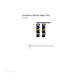
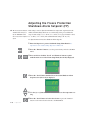
EarthSmart
Portable Chillers
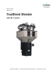
Water-cooled models ECW-1.5 to ECW-30
Air-cooled models ECA-1.5 to ECA-30
Corporate Office: 724.584.5500 l Instant Access 24/7 (Parts and Service): 800.458.1960 l Parts and Service: 814.437.6861
Please record your equipment’s
model and serial number(s) and
the date you received it in the
spaces provided.
It’s a good idea to record the model and serial number(s) of your equipment and
the date you received it in the User Guide. Our service department uses this information, along with the manual number, to provide help for the specific equipment
you installed.
Please keep this User Guide and all manuals, engineering prints and parts lists
together for documentation of your equipment.
Date:
Manual Number: UGH030-1012
Serial Number(s):
Model Number(s):
DISCLAIMER: The Conair Group, Inc., shall not be liable for errors contained in this User Guide or
for incidental, consequential damages in connection with the furnishing, performance or use of
this information. Conair makes no warranty of any kind with regard to this information, including,
but not limited to the implied warranties of merchantability and fitness for a particular purpose.
Copyright 2012 l The Conair Group l All rights reserved
Ta b l e o f C o n t e n t s
1-1 I n t r o d u c t i o n
Purpose of the user guide . . . . . . . . . . . . . . . . . . . . . . . . . . . . . . . . 1-2
How the guide is organized . . . . . . . . . . . . . . . . . . . . . . . . . . . . . . 1-2
Your responsibilities as a user . . . . . . . . . . . . . . . . . . . . . . . . . . . . . 1-3
ATTENTION: Read this so no one gets hurt . . . . . . . . . . . . . . . . . . . 1-4
How to use the lockout device (optional) . . . . . . . . . . . . . . . . . . . . . 1-6
2-1 D e s c r i p t i o n
What is the EarthSmart Portable Chiller? . . . . . . . . . . . . . . . . . . . . .2-2
Typical applications . . . . . . . . . . . . . . . . . . . . . . . . . . . . . . . . . . . . .2-3
Limitations . . . . . . . . . . . . . . . . . . . . . . . . . . . . . . . . . . . . . . . . . . . 2-3
How it works: EarthSmart ECW Series (Water-cooled models) . . . . .2-4
Process circulation . . . . . . . . . . . . . . . . . . . . . . . . . . . . . . . . 2-4
Refrigerant circulation. . . . . . . . . . . . . . . . . . . . . . . . . . . . . . 2-5
How it works: EarthSmart ECA Series (Air-cooled models). . . . . . . . 2-6
Process circulation . . . . . . . . . . . . . . . . . . . . . . . . . . . . . . . . 2-6
Refrigerant circulation. . . . . . . . . . . . . . . . . . . . . . . . . . . . . . 2-7
Portable chiller features . . . . . . . . . . . . . . . . . . . . . . . . . . . . . . . . . 2-8
Water-cooled models . . . . . . . . . . . . . . . . . . . . . . . . . . . . . . 2-8
Air-cooled models . . . . . . . . . . . . . . . . . . . . . . . . . . . . . . . . . 2-9
Specifications:. . . . . . . . . . . . . . . . . . . . . . . . . . . . . . . . . . . . . . . . 2-10
EarthSmart ECW Series (Water-cooled models) . . . . . . . . . . 2-10
EarthSmart ECA Series (Air-cooled models). . . . . . . . . . . . . 2-11
Pump curves. . . . . . . . . . . . . . . . . . . . . . . . . . . . . . . . . . . . . . . . . 2-12
ECW Series (Water-cooled) . . . . . . . . . . . . . . . . . . . . . . . . . 2-12
ECA Series (Air-cooled) . . . . . . . . . . . . . . . . . . . . . . . . . . . . 2-13
EarthSmart chiller options . . . . . . . . . . . . . . . . . . . . . . . . . . . . . . . 2-14
Ta b l e o f C o n t e n t s l i
3-1 I n s t a l l a t i o n
Unpacking the boxes . . . . . . . . . . . . . . . . . . . . . . . . . . . . . . . . . . . 3-2
Warnings and cautions . . . . . . . . . . . . . . . . . . . . . . . . . . . . . . . . . . 3-3
Preparing for installation . . . . . . . . . . . . . . . . . . . . . . . . . . . . . . . . . 3-4
Making process plumbing connections . . . . . . . . . . . . . . . . . . . . . . 3-5
Filling the chiller . . . . . . . . . . . . . . . . . . . . . . . . . . . . . . . . . . . . . . . 3-7
Checking refrigerant charge . . . . . . . . . . . . . . . . . . . . . . . . . . . . . . 3-9
Connecting the main power source . . . . . . . . . . . . . . . . . . . . . . . . 3-10
Checking electrical connections . . . . . . . . . . . . . . . . . . . . . . . . . . 3-12
Checking pump rotation . . . . . . . . . . . . . . . . . . . . . . . . . . . . . . . . 3-13
Checking the scroll compressor . . . . . . . . . . . . . . . . . . . . . . . . . . 3-14
Checking the water level gauge . . . . . . . . . . . . . . . . . . . . . . . . . . 3-14
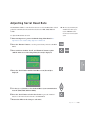
Adjusting the bypass valve (optional). . . . . . . . . . . . . . . . . . . . . . . 3-15
Installing alarm indicators (optional) . . . . . . . . . . . . . . . . . . . . . . . 3-16
4-1 O p e r a t i o n
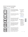
Basic control features . . . . . . . . . . . . . . . . . . . . . . . . . . . . . . . . . . . 4-4
EarthSmart Chiller control functions . . . . . . . . . . . . . . . . . . . . . . . . 4-5
Control function flow charts . . . . . . . . . . . . . . . . . . . . . . . . . . . . . . 4-5
How to navigate the menu tree . . . . . . . . . . . . . . . . . . . . . . . . . . . . 4-5
EarthSmart Chiller menu tree . . . . . . . . . . . . . . . . . . . . . . . . . . . . . 4-6
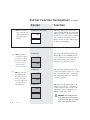
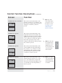
Control function descriptions. . . . . . . . . . . . . . . . . . . . . . . . . . . . . 4-14
Before starting . . . . . . . . . . . . . . . . . . . . . . . . . . . . . . . . . . . . . . . 4-40
Starting the chiller. . . . . . . . . . . . . . . . . . . . . . . . . . . . . . . . . . . . . 4-41
Stopping the chiller . . . . . . . . . . . . . . . . . . . . . . . . . . . . . . . . . . . . 4-42
EarthSmart Chiller sequence of operation . . . . . . . . . . . . . . . . . . . 4-43
Adjusting setpoint temperature . . . . . . . . . . . . . . . . . . . . . . . . . . . 4-44
How to use the supervisor’s password . . . . . . . . . . . . . . . . . . . . . 4-45
Autotuning requirements . . . . . . . . . . . . . . . . . . . . . . . . . . . . . . . . 4-46
Autotuning procedure . . . . . . . . . . . . . . . . . . . . . . . . . . . . . . . . . . 4-46
i i l Ta b l e o f C o n t e n t s
Changing from fahrenheit to celsius units . . . . . . . . . . . . . . . . . . . 4-49
Enabling/Disabling display decimal point for temperature . . . . . . . 4-50
Glycol operation enable/disable. . . . . . . . . . . . . . . . . . . . . . . . . . . 4-51
Adjusting the process variable selection . . . . . . . . . . . . . . . . . . . . 4-52
Autofill enable/disable (optional) . . . . . . . . . . . . . . . . . . . . . . . . . . 4-53
Setting serial Modbus communication ID . . . . . . . . . . . . . . . . . . . 4-54
Adjusting serial baud rate . . . . . . . . . . . . . . . . . . . . . . . . . . . . . . . 4-55
Setting alarm parameters . . . . . . . . . . . . . . . . . . . . . . . . . . . . . . . 4-56
Adjusting the low pressure inhibit time . . . . . . . . . . . . . . . . . . . . . 4-56
Adjusting the low pressure delay time. . . . . . . . . . . . . . . . . . . . . . 4-58
Adjusting the flow switch alarm inhibit time . . . . . . . . . . . . . . . . . 4-59
Adjusting the flow switch alarm delay time . . . . . . . . . . . . . . . . . . 4-60
Adjusting the process high alarm setpoint. . . . . . . . . . . . . . . . . . . 4-61
Adjusting the process high alarm inhibit time . . . . . . . . . . . . . . . . 4-62
Adjusting the process high alarm delay time. . . . . . . . . . . . . . . . . 4-63
Adjusting the process high temperature shutdown setpoint . . . . . 4-64
Adjusting the process high temperature shutdown inhibit time . . . 4-65
Adjusting the process high temperature shutdown delay time. . . . 4-66
Adjusting the process low alarm setpoint . . . . . . . . . . . . . . . . . . . 4-67
Adjusting the process low alarm inhibit time. . . . . . . . . . . . . . . . . 4-68
Adjusting the process low alarm delay time . . . . . . . . . . . . . . . . . 4-69
Adjusting the process deviation high alarm setpoint . . . . . . . . . . . 4-70
Adjusting the process deviation low alarm setpoint. . . . . . . . . . . . 4-71
Adjusting the process deviation high alarm inhibit time. . . . . . . . . 4-72
Adjusting the process deviation high alarm delay time . . . . . . . . . 4-73
Adjusting the process deviation low shutdown alarm setpoint. . . . 4-74
Enabling/Disabling process loop break . . . . . . . . . . . . . . . . . . . . . 4-75
Adjusting the process loop breaker timer . . . . . . . . . . . . . . . . . . . 4-76
Adjusting the alarm silence timer . . . . . . . . . . . . . . . . . . . . . . . . . 4-77
Adjusting the autofill alarm timer . . . . . . . . . . . . . . . . . . . . . . . . . 4-78
Adjusting the compressor cycles per hour alarm setpoint . . . . . . . 4-79
Adjusting the freeze protection shutdown alarm setpoint . . . . . . . 4-80
Ta b l e o f C o n t e n t s l i i i
5-1 M a i n t e n a n c e
Maintenance features . . . . . . . . . . . . . . . . . . . . . . . . . . . . . . . . . . . 5-2
Warnings and cautions . . . . . . . . . . . . . . . . . . . . . . . . . . . . . . . . . . 5-3
Preventative maintenance schedule . . . . . . . . . . . . . . . . . . . . . . . . 5-4
Checking electrical connections . . . . . . . . . . . . . . . . . . . . . . . . . . . 5-6
Cleaning the brazed plate evaporator or water-cooled condenser . . 5-7
Cleaning the air-cooled condenser . . . . . . . . . . . . . . . . . . . . . . . . 5-10
Checking the refrigerant charge and quality . . . . . . . . . . . . . . . . . 5-11
Checking the compressor’s oil level . . . . . . . . . . . . . . . . . . . . . . . 5-12
Checking the hot-gas bypass valve operation . . . . . . . . . . . . . . . . 5-14
Cleaning the evaporator and condenser “Y” strainer . . . . . . . . . . . 5-16
Checking or cleaning the flow switch . . . . . . . . . . . . . . . . . . . . . . 5-20
Checking reservoir level . . . . . . . . . . . . . . . . . . . . . . . . . . . . . . . . 5-22
Checking pump performance . . . . . . . . . . . . . . . . . . . . . . . . . . . . 5-23
Reloading factory default parameters . . . . . . . . . . . . . . . . . . . . . . 5-24
6-1 Tr o u b l e s h o o t i n g
Before beginning. . . . . . . . . . . . . . . . . . . . . . . . . . . . . . . . . . . . . . . 6-2
Identify the cause of a problem . . . . . . . . . . . . . . . . . . . . . . . . . . . 6-2
A few words of caution . . . . . . . . . . . . . . . . . . . . . . . . . . . . . . . . . 6-3
TROUBLESHOOTING
Chiller problems . . . . . . . . . . . . . . . . . . . . . . . . . . . . . . . . . . . . . . . 6-4
Autotuning errors . . . . . . . . . . . . . . . . . . . . . . . . . . . . . . . . . . . . . . 6-6
Passive alarms . . . . . . . . . . . . . . . . . . . . . . . . . . . . . . . . . . . . . . . . 6-8
Shut down alarms. . . . . . . . . . . . . . . . . . . . . . . . . . . . . . . . . . . . . 6-13
Additional alarms . . . . . . . . . . . . . . . . . . . . . . . . . . . . . . . . . . . . . 6-20
Replacing the RTD. . . . . . . . . . . . . . . . . . . . . . . . . . . . . . . . . . . . . 6-22
Removing pump components . . . . . . . . . . . . . . . . . . . . . . . . . . . . 6-23
Replacing the contactor . . . . . . . . . . . . . . . . . . . . . . . . . . . . . . . . 6-24
i v l Ta b l e o f C o n t e n t s
A Appendix
We’re here to help . . . . . . . . . . . . . . . . . . . . . . . . . . . . . . . . A-1
How to contact customer service . . . . . . . . . . . . . . . . . . . . . A-1
Before you call... . . . . . . . . . . . . . . . . . . . . . . . . . . . . . . . . . . A-1
Equipment guarantee . . . . . . . . . . . . . . . . . . . . . . . . . . . . . . A-2
Performance warranty. . . . . . . . . . . . . . . . . . . . . . . . . . . . . . A-2
Warranty limitations . . . . . . . . . . . . . . . . . . . . . . . . . . . . . . . A-2
B Appendix
Maintenance log . . . . . . . . . . . . . . . . . . . . . . . . . . . . . . . . . . B-1
C Appendix
Pressure tables . . . . . . . . . . . . . . . . . . . . . . . . . . . . . . . . . . . C-1
D Appendix
Water quality control. . . . . . . . . . . . . . . . . . . . . . . . . . . . . . . D-1
E
Appendix
Overhead plumbing details . . . . . . . . . . . . . . . . . . . . . . . . . . E-1
F
Appendix
RTD resistance chart . . . . . . . . . . . . . . . . . . . . . . . . . . . . . . . F-1
G Appendix
Installing autofill (optional) . . . . . . . . . . . . . . . . . . . . . . . . . . G-1
H Appendix
Cleaning the autofill valve (optional) . . . . . . . . . . . . . . . . . . . H-1
Ta b l e o f C o n t e n t s l v
I
Appendix
Compressor module troubleshooting . . . . . . . . . . . . . . . . . . . I-1
J
Appendix
Motor protection . . . . . . . . . . . . . . . . . . . . . . . . . . . . . . . . . . J-1
K Appendix
EarthSmart chiller - Serial Modbus communications . . . . . . . K-1
EarthSmart chiller - Ethernet communications . . . . . . . . . . . K-2
EarthSmart chiller Modbus and Ethernet communications. . . K-4
L
Appendix
Pressure switch settings. . . . . . . . . . . . . . . . . . . . . . . . . . . . L-1
M Appendix
Resetting the high pressure switch. . . . . . . . . . . . . . . . . . . . M-1
v i l Ta b l e o f C o n t e n t s
SECTION
1
Purpose of the user guide . . . . . . . . . . . . . . 1-2
How the guide is organized . . . . . . . . . . . . . 1-2
Yo u r r e s p o n s i b i l i t i e s a s a u s e r . . . . . . . . . . . 1 - 3
AT T E N T I O N :
Read this so no one gets hurt . . . . . . . . 1-4
How to use the lockout device (optional) . . . . 1-6
Introduction l 1-1
1
Introduction
Introduction
Purpose of the User Guide
This User Guide describes Conair’s EarthSmart Portable Chiller and
explains step-by-step how to install, operate, maintain and repair this
equipment.
Before installing this product, please take a few moments to read the User
Guide and review the diagrams and safety information in the instruction
packet. You also should review manuals covering associated equipment in
your system. This review won’t take long, and it could save you valuable
installation and operating time later.
How the Guide is Organized
Symbols have been used to help organize the User Guide and call your
attention to important information regarding safe installation and operation.
Symbols within triangles warn of conditions that could be hazardous to users or
could damage equipment. Read and take precautions before proceeding.
1
Numbers indicate tasks or steps to be performed by the user.
◆
A diamond indicates the equipment’s response to an action performed by the user.
❒
An open box marks items in a checklist.
•
A circle marks items in a list.
✒
✐
1-2 l Introduction
Indicates a tip. A tip is used to provide you with a suggestion that will help you with
the maintenance and the operation of this equipment.
Indicates a note. A note is used to provide additional information about the steps
you are following throughout the manual.
Yo u r R e s p o n s i b i l i t y a s a U s e r
• Thorough review of this User Guide, paying particular attention
to hazard warnings, appendices, and related diagrams.
• Thorough review of the equipment itself, with careful attention
to voltage sources, intended use and warning labels.
• Thorough review of instruction manuals for associated equipment.
• Step-by-step adherence to instructions outlined in this User Guide.
Introduction l 1-3
1
Introduction
You must be familiar with all safety procedures concerning installation, operation and maintenance of this equipment. Responsible safety procedures include:
AT T E N T I O N :
Read this so no one gets hurt
We design equipment with the user’s safety in mind. You can avoid the potential
hazards identified on this machine by following the procedures outlined below and
elsewhere in the User Guide.
WA R N I N G : I m p r o p e r i n s t a l l a t i o n , o p e r a t i o n o r
servicing may result in equipment damage or
p e r s o n a l i n j u r y.
This equipment should be installed, adjusted, and serviced by a qualified technician who is familiar with the construction, operation and
potential hazards of this type of machine.
All wiring, disconnects, and fuses should be installed by a qualified
electrical technician in accordance with electrical codes in your region.
Always maintain a safe ground. Do not operate this equipment at
power levels other than what is specified on the machine serial tag and
data plate.
WA R N I N G : Vo l t a g e h a z a r d
This equipment is powered by three-phase alternating current,
as specified on the machine serial tag and data plate.
A properly-sized conductive ground wire from the incoming power
supply must be connected to the chassis ground terminal inside the
electrical enclosure. Improper grounding can result in severe personal
injury and erratic machine operation.
Always disconnect and lock out the incoming main power source before
opening the electrical enclosure or performing non-standard operating
procedures, such as routine maintenance. Only qualified personnel
should perform troubleshooting procedures that require access to the
electrical enclosure while power is on.
(continued)
1-4 l Introduction
AT T E N T I O N :
Read this so no one gets hurt
(continued)
Always protect yourself from hot surfaces when working on the
EarthSmart Portable Chiller, especially when working on or around the
compressor and condenser. These devices can reach up to 160°F
{71°C}. Allow these devices to cool before performing any maintenance
or troubleshooting.
CA U T I O N : Ve n t i l a t i o n h a z a r d
The unit requires a clean and well ventilated operating environment. Do
not place anything on top of the unit while operating. Units with top
exhaust fans require unrestricted outlet air flow.
Water-cooled units require a minimum of 1 ft. {30.5 cm} clearance
around the perimeter for serviceability. Conair recommends 2 ft.
{60.9 cm} for ease of servicing. Air-cooled units require a minimum of
2 ft. {60.9 cm} clearance around the perimeter for serviceability and
proper air flow.
WARNING: Refrigerant hazard
Only certified refrigerant technicians should examine and correct problems involving the refrigerant circuit.
Introduction l 1-5
1
Introduction
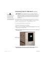
CA U T I O N : H o t S u r fa c e s
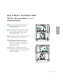
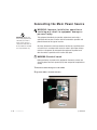
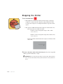
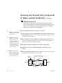
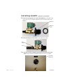
How to Use the Lockout Device
(optional)
CAUTION: Before performing maintenance or repairs on this product, you should
disconnect and lockout electrical power sources to prevent injury from unexpected
energization or start-up. A lockable device is available as an option to isolate the
chiller from potentially hazardous electricity.
Lockout is the preferred method of isolating machines or equipment from energy
sources. Your Conair EarthSmart Portable Chiller can be equipped with the
optional lockout device pictured below.
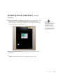
To use the lockout device:
1 Stop or turn off the equipment.
2 Isolate the equipment from the electric power. Turn the rotary disconnect
switch to the OFF or “O” position.
3 Secure the device with an assigned lock or tag. Insert a lock or tag in the
holes to prevent movement.
4 The equipment is now locked out.
WARNING: Before removing lockout devices and returning switches to the ON
position, make sure that all personnel are clear of the machine, tools have been
removed, and all safety guards re-installed.
To restore power to the chiller, turn the rotary disconnect back to the ON position:
1 Remove the lock or tag.
2 Turn the rotary disconnect switch to the ON or “I” position.
1-6 l Introduction
SECTION
Description
W h a t i s t h e E a r t h S m a r t Po r t a b l e C h i l l e r ? . . . . 2 - 2
2
Ty p i c a l a p p l i c a t i o n s . . . . . . . . . . . . . . . . . . 2 - 3
Limitations . . . . . . . . . . . . . . . . . . . . . . . . 2-3
How it works: EarthSmart ECW Series
Process circulation . . . . . . . . . . . . . . . 2-4
Refrigerant circulation . . . . . . . . . . . . . 2-5
How it works: EarthSmart ECA Series
( A i r- c o o l e d m o d e l s ) . . . . . . . . . . . . . . . 2 - 6
Process circulation . . . . . . . . . . . . . . . 2-6
Refrigerant circulation . . . . . . . . . . . . . 2-7
Po r t a b l e c h i l l e r f e a t u r e s . . . . . . . . . . . . . . . 2 - 8
Wa t e r- c o o l e d m o d e l s . . . . . . . . . . . . . . 2 - 8
A i r- c o o l e d m o d e l s . . . . . . . . . . . . . . . . 2 - 9
Specifications: . . . . . . . . . . . . . . . . . . . . 2-10
EarthSmart ECW Series
( Wa t e r- c o o l e d m o d e l s ) . . . . . . . . . . 2 - 1 0
EarthSmart ECA Series
( A i r- c o o l e d m o d e l s ) . . . . . . . . . . . 2 - 1 1
Pump curves . . . . . . . . . . . . . . . . . . . . . . 2-12
E C W S e r i e s ( Wa t e r- c o o l e d ) . . . . . . . . . 2 - 1 2
E C A S e r i e s ( A i r- c o o l e d ) . . . . . . . . . . . . 2 - 1 3
EarthSmart chiller options . . . . . . . . . . . . . 2-14
Description l 2-1
2
Description
( Wa t e r- c o o l e d m o d e l s ) . . . . . . . . . . . . . 2 - 4
W h a t i s t h e E a r t h S m a r t Po r t a b l e
Chiller?
The Conair EarthSmart Portable Chillers provide self-contained sources of
chilled water and are available in either water- or air-cooled models. The
EarthSmart Chillers have ranges from 1.5 Hp to 30 Hp with approximate capacities of 1.5 to 30 tons of refrigeration. Pump selections are available to match
most process flow and pressure requirements.
Conair EarthSmart Portable Chillers are designed to provide chilled fluid for
industrial applications requiring 24-hour-a-day performance. Units are totally
self-contained for easy, economical installation. All parts wetted by the process
are non-ferrous.
To operate, simply connect the power source, process piping and fill with water
or with a mixture of water and industrial grade ethylene glycol or propylene
glycol (not automotive antifreeze). Then set the process temperature.
These chillers are ideal for machine-side cooling to maintain process temperatures in an injection molding machine, extruder or wherever you need a small,
moveable cooling unit. Nominal capacities range from 1.4 to 29.7 tons for the
water-cooled models and 1.2 to 28.8 tons for the air-cooled models. Capacities
are based on standard pump sizes and delivering 50°F {10°C} coolant.
Operation of these units differ only in the medium used to remove heat from the
refrigerant in the condensers. Water-cooled models are rated to use 85°F
{29°C} or lower cooling water from a tower, well, or city service; air-cooled
models are rated to use ambient air up to 95°F {35°C}.
2-2 l Description
Ty p i c a l A p p l i c a t i o n s
The Conair EarthSmart Portable Chiller can be used anywhere a reliable source
of process cooling water - with stable temperature control - is required.
Portable chillers are available for:
Limitations
EarthSmart Portable Chillers should be chosen based upon:
• Cooling load - Select a chiller that has 0 - 10% more capacity than the
process load.
• Location - Choose a water-cooled chiller when tower water or another
inexpensive water source is available. Choose an air-cooled model for
maximum portability of the unit or if an inexpensive water source is
unavailable.
• Temperature - The normal temperature range of discharge chilled water is
20°F to 70°F {-6.7°C to 21.1°C}. For applications requiring 40°F {4.4°C}
and lower process fluid temperatures, mix an industrial grade ethylene or
propylene glycol with the water to the correct percentage, by volume, to
protect against process freezing. See Installation section entitled, Filling the
Chiller.
Use this information as a general guide. Consult your Conair representative for
assistance when choosing a Conair EarthSmart Portable Chiller.
Description l 2-3
2
• Blow molding
• Extrusion
• Metal plating
• Laser
• Heatset/web offset printing presses
Description
• Injection molding
• Thermoforming
• Air compressors
• Anodizing
• Degreasing
• Dryer intercoolers/aftercoolers.
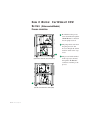
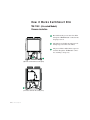
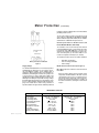
H o w i t Wo r k s : E a r t h S m a r t E C W
S e r i e s ( Water-cooled Models)
Process circulation
1 Hot fluid from the process
enters the chiller through the
“From Process” connection
into the pump reservoir.
2 The pump draws water from
the pump reservoir and
moves it through the strainer
and flow switch to the evaporator.
2
1
3 The process fluid is chilled
(right-side as view from the control panel)
3
(left-side as view from the control panel)
2-4 l Description
in the evaporator and exits
through the “To Process”
connection, returning to the
process.
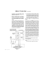
H o w i t Wo r k s : E a r t h S m a r t E C W
S e r i e s ( Water-cooled Models) ( c o n t i n u e d )
Refrigerant circulation
1 The evaporator extracts heat from the process
3
2
4
2 Vaporized refrigerant travels from the evaporator to the compressor, where the low-pressure
vapor is compressed into a high-pressure,
high-temperature vapor.
3 The high-pressure, high-temperature vapor from
1
the compressor travels to the condenser.
5
4 The high-pressure, high-temperature vapor
travels from the condenser to the receiver.
Water tower or city water removes heat from
the vapor, condensing it to a high-pressure,
high-temperature liquid.
(left-side as view from the control panel)
5 High-pressure, high-temperature liquid is
metered back to the evaporator by the expansion
valve (TXV), changing it to a low-pressure, lowtemperature liquid/vapor.
2
4
3
5
(right-side as view from the control panel)
Description l 2-5
2
Description
fluid, causing the refrigerant to vaporize
(evaporate) into a gas.
H o w i t Wo r k s E a r t h S m a r t E CA
S e r i e s ( Air-cooled Models)
Process circulation
1 Hot fluid from the process enters the chiller
through the “From Process” connection into
the pump reservoir.
2
1
(right-side as view from the control panel)
3
(left-side as view from the control panel)
2-6 l Description
2
The pump moves fluid from pump reservoir
through evaporator where it is chilled.
3
The process fluid is chilled in the evaporator
and exits through the “To Process” connection, returning to the process.
H o w i t Wo r k s : E a r t h S m a r t E CA
S e r i e s ( Air-cooled Models) ( c o n t i n u e d )
Refrigerant circulation
1 The evaporator extracts heat from the process fluid,
causing the refrigerant to vaporize (evaporate) into a gas.
low-pressure vapor is compressed into a high-pressure,
high-temperature vapor.
2
3 The high-pressure, high-temperature vapor travels from the
compressor through the condenser, where the fan cools
and condenses the vapor into a high-pressure, hightemperature liquid.
1
4
4 High-pressure, high-temperature liquid is metered back to
the evaporator by the expansion valve (TXV), changing it
to a low-pressure, low-temperature liquid/vapor.
(left-side as view from the control panel)
3
(right-side as view from the control panel)
Description l 2-7
2
Description
2 Vaporized refrigerant travels to the compressor, where the
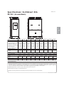
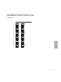
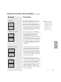
Po r t a b l e C h i l l e r Fe a t u r e s
(Water-cooled models)
1
2
3
5
4
12 10
17
16
11
13
6
14
8
2-8 l Description
15
7
(left-side as view from the control panel)
1
2
3
4
5
6
7
8
9
9
Hot-gas bypass valve (HGBP)
Relief valve
Condenser
Compressor
Receiver
Liquid line solenoid valve (LLSV)
TX valve (Expansion valve)
Process pump
Pump reservoir
(right-side as view from the control panel)
10 Filter dryer
11 Evaporator
12 Flow switch
13 “Y” strainer
14 “To” temperature sensor
15 “From” temperature sensor
16 Evaporator temperature sensor
17 Liquid line sight glass
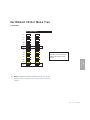
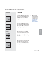
Po r t a b l e C h i l l e r Fe a t u r e s
(continued)
(Air-cooled models)
2
1
4
8
10 15
7
16
12
11
6
9
5
13
(right-side as view from the control panel)
(left-side as view from the control panel)
1
2
3
4
5
6
7
8
9
Hot-gas bypass valve (HGBP)
Fan(s)
Condenser
Compressor
Process pump
Pump reservoir
Evaporator
14
10 Flow switch
11 Liquid line solenoid valve (LLSV)
12 “Y” strainer
13
14
15
16
“To” temperature sensor
“From” temperature sensor
Evaporator temperature sensor
Liquid line sight glass
Filter dryer
TX valve (Expansion valve)
Description l 2-9
2
Description
3
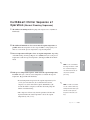
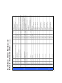
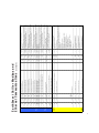
Specifications: EarthSmart ECW
S e r i e s ( Water-cooled Models)
TPHX038-1011
A
B
MODEL
Performance characteristics
Nominal capacity* tons {kW}
Compressor qty/Hp {kW}
Standard process pump† Hp {kW}
Standard process flow gpm {l/min}
Standard process pressure PSI {bar}‡
Reservoir capacity gal {l}
Condenser water flow gpm {l/min}
Dimensions inches {mm}
A - Height
B - Width
C - Depth
Approximate weight lb {kg}
Installed
Shipping
Connections inches {mm}
Process connections NPT
Condenser connections NPT
Voltages full load amps
460/3 phase/60 Hz
C
ECW-1.5
ECW-3
ECW-5
1.6 {5.6}
(1) 1.5 {1.12}
0.75 {0.56}
4.0 {15.1}
33.0 {2.28}
10 {37.9}
5.3 {20.1}
2.9 {10.2}
(1) 3 {2.24}
1.0 {0.75}
7.0 {26.5}
38.0 {2.62}
10 {37.9}
9.3 {35.2}
5.4 {19.0}
(1) 5 {3.73}
1.5 {1.12}
14.0 {53.0}
42.0 {2.9}
25 {94.6}
17.1 {64.7}
ECW-7.5
ECW-10
7.3 {25.7}
10.3 {36.2}
(1) 7.5 {5.59} (1) 10 {7.46}
1.5 {1.12}
1.5 {1.12}
18.0 {68.1} 26.0 {98.4}
41.0 {2.83} 39.0 {2.69}
25 {94.6}
25 {94.6}
22.9 {86.7} 30.8 {116.6}
ECW-15
ECW-20
15.2 {53.5} 19.4 {68.2}
(1) 15 {11.19} (1) 20 {14.91}
2.0 {1.50}
3.0 {2.25}
37.0 {140.0} 48.0 {181.7}
37.0 {2.55} 33.0 {2.28}
50 {189.3} 75 {283.9}
46.1 {174.5} 59.4 {224.9}
ECW-25
ECW-30
24.4 {85.8}
(1) 25 {18.64}
3.0 {2.25}
60.0 {227.1}
27.0 {1.86}
75 {283.9}
69.5 {263.1}
31.9 {112.2}
(1) 30 {22.37}
5.0 {3.73}
79.0 {299.0}
43.0 {2.96}
75 {283.9}
97.4 {368.7}
40.00 {1016} 40.00 {1016} 56.41 {1433} 56.41 {1433} 57.78 {1468} 66.78 {1696} 76.19 {1935} 76.19 {1935} 76.19 {1935}
27.0 {686}
27.0 {686} 33.0 {838}
33.0 {838}
33.0 {838} 43.0 {1092} 45.50 {1156} 45.50 {1156} 45.50 {1156}
45.0 {1143} 45.0 {1143} 51.88 {1318} 51.88 {1318} 55.88 {1419} 63.5 {1613} 72.94 {1853} 72.94 {1853} 73.03 {1855}
450 {204}
500 {227}
475 {216}
525 {238}
685 {311}
735 {333}
1130 {513}
1180 {535}
1240 {563}
1290 {585}
1480 {671}
1530 {694}
1515 {687}
1685 {764}
1750 {794}
1950 {885}
1985 {900}
2215 {1005}
1.0 {26}
1.0 {26}
1.0 {26}
1.0 {26}
1.5 {38}
1.0 {26}
1.5 {38}
1.5 {38}
1.5 {38}
1.5 {38}
1.5 {38}
1.5 {38}
2.5 {64}
2.0 {51}
2.5 {64}
2.0 {51}
2.5 {64}
2.0 {51}
6.6
9.8
15.4
20.0
23.6
34.0
38.9
52.0
68.3
SPECIFICATION NOTES:
* Based on supplying 50°F {10°C} water (no antifreeze) to process, standard single pump selections, maximum of 95°F {35°C} ambient air and 60 Hz operation. Adjust capacities up 2% per degree for operation above 50°F {10°C} to a maximum of 65°F {18°C}. Adjust capacities down 2% per degree for operation below 50°F {10°C} to a minimum of 20°F {-7°C}. Capacities are +/- 5% based on the compressor manufacturer's ratings and are subject to change without notice. Consult with a Conair representative for other conditions. Capacities change depending on selected options.
† Standard design based on 50°F {10°C} to process with 60°F {16°C} return from process. Condenser water based on 85°F {29°C} supply and 95°F {35°C}
return.
‡ Standard pump pressure rating does not include internal chiller losses.
Specifications may change without notice. Check with your Conair representative for the most current information.
2-10 l Description
S p e c i f i c a t i o n s : E a r t h S m a r t E CA
S e r i e s ( Air-cooled Models)
TPHX037-1011
A
C
ECA-1.5
ECA-3
ECA-5
ECA-7.5
ECA-10
ECA-15
ECA-20
ECA-25
ECA-30
Performance characteristics
Nominal capacity* tons {kW}
1.5 {5.3}
3.0 {10.5}
5.0 {17.6}
8.0 {28.1}
10.4 {36.5}
14.1 {49.5}
22.6 {79.4}
24.8 {87.1}
29.4 {103.3}
Compressor qty/Hp {kW}
Standard process pump† Hp {kW}
(1) 1.5 {1.12}
(1) 3 {2.24}
(1) 5 {3.73}
(1) 7.5 {5.59}
(1) 10 {7.46}
(1) 15 {11.19}
(1) 20 {14.91}
(1) 25 {18.64}
(1) 30 {22.37}
0.75 {0.56}
1.0 {0.75}
1.5 {1.12}
1.5 {1.12}
1.5 {1.12}
2.0 {1.50}
3.0 {2.25}
3.0 {2.25}
5.0 {3.73}
Standard process flow gpm {l/min}
4.0 {15.1}
8.0 {30.3}
13.0 {49.2}
20.0 {75.7}
26.0 {98.4}
35.0 {132.5}
56.0 {212.0}
61.0 {230.9}
73.0 {276.3}
Standard process pressure psi {bar}‡
33.0 {2.28}
38.0 {2.62}
43.0 {2.96}
40.0 {2.76}
39.0 {2.69}
38.0 {2.62}
29.0 {2.00}
28.0 {1.93}
45.0 {3.10}
10 {37.9}
10 {37.9}
25 {94.6}
25 {94.6}
25 {94.6}
50 {189.3}
75 {283.9}
75 {283.9}
75 {283.9}
(1) 1.15 {0.86} (1) 1.15 {0.86}
(1) 1.5 {1.10}
(2) 1.4 {1.05}
(2) 1.4 {1.05}
(1) 3.0 {2.25}
(2) 1.4 {1.05}
(2) 3.0 {2.25}
(2) 3.0 {2.25}
A - Height
54.63 {1388}
54.63 {1388}
74.06 {1881}
81.34 {2066}
81.34 {2066}
86.41 {2195}
90.66 {2303}
88.56 {2250}
88.56 {2250}
B - Width
27.00 {686}
27.0 {686}
33.0 {838}
33.0 {838}
33.0 {838}
43.0 {1092}
45.50 {1156}
45.50 {1156}
45.50 {1156}
C - Depth
46.88 {1191}
46.91 {1192}
51.88 {1318}
63.50 {1613}
63.50 {1613}
63.50 {1613}
75.88 {1927}
76.09 {1933}
76.09 {1933}
1.0 {25}
1.0 {25}
1.5 {38}
1.5 {38}
1.5 {38}
2.0 {51}
2.5 {64}
2.5 {64}
2.5 {64}
Reservoir capacity gal {l}
Condenser fan qty/fan Hp {kW} each
Dimensions inches {mm}
Connections inches {mm}
Process connections NPT
Approximate weight lb {kg}
Installed
485 {220}
535 {243}
1050 {476}
1540 {699}
1680 {762}
1850 {839}
1905 {864}
2113 {958}
2320 {1052}
Shipped
535 {243}
580 {263}
1100 {499}
1590 {721}
1730 {785}
1900 {862}
2075 {941}
2313 {1049}
2550 {1157}
7.6
11.4
17.2
23.6
27.5
38.1
54.8
75.2
76.7
Voltages full load amps
460/3 phase/60 Hz
SPECIFICATION NOTES:
* Based on 50°F {10°C} supply water (no antifreeze) to the process, standard single pump selections, a maximum of 95°F {35°C} ambient air and 60 Hz operation. Adjust capacities up 2% per degree for operation above 50°F {10°C} to a maximum of 65°F {18°C}. Adjust capacities down 2% per degree of operation below 50°F {10°C} to a minimum of 20°F {-7°C}. Capacities are +/- 5% based on the compressor manufacturer's ratings and are subject to change without notice. Consult with a Conair representative for other conditions. Capacities change depending on selected options.
† Standard design based on 50°F {10°C} to process with 60°F {16°C} return from process.
‡ Standard pump pressure rating does not include internal chiller losses.
Specifications may change without notice. Check with your Conair representative for the most current information.
Description l 2-11
2
Description
B
MODEL
Pump curves - ECW Series
TPHX038-1011
( Wa t e r- c o o l e d )
100
90
Pressure* (psi)
80
70
15 Hp
60
10 Hp
50
5 Hp
40
3
7.5 Hp
Hp
)(A
30
1.5 Hp
0
,1
.5
,7
,5
-3
W
EC
60
80
2 Hp
20
EC
W20
&
25
&
1 Hp
3H
p(
B)
-
15
0.75 Hp
10
0
0
10
20
30
40
50
70
90 100 110 120 130 140 150 160 170 180 190 200
Flow Rate (gpm)
SPECIFICATION NOTES
Pump availability: 0.75 Hp standard for 1.5 ton; 1 Hp standard for 3 ton; 1.5 Hp standard for 5, 7.5 and 10 ton and optional for
1.5 ton; 2 Hp standard for 15 ton and optional for 3 ton; 3 Hp (A) optional for 3, 5, 7.5 and 10 ton; 3 Hp (B) standard for 20 and
25 ton; 5 Hp standard for 30 ton and optional for 5 and 15 ton; 7.5 Hp optional for 7.5, 10, 20, 25 and 30 ton; 10 Hp optional for
15 ton; 15 Hp optional for 20, 25 and 30 ton.
* Pump curves do not reflect pressure drops due to internal piping.
These pump curves are non-overloading using the service factor of the motors.
Specifications may change without notice. Check with your Conair representative for the most current information.
2-12 l Description
P u m p c u r v e s - E CA S e r i e s
TPHX037-1011
( A i r- c o o l e d )
100
90
80
15 Hp
60
10 Hp
50
5 Hp
40
3
Hp
7.5 Hp
)(A
10
5,
7.
5,
3,
AEC
30
3H
p(
B)
-
EC
A20
&
2 Hp
20
1.5 Hp
&
15
1 Hp
25
0.75 Hp
10
0
0
10
20
30
40
50
60
70
80
90 100 110 120 130 140 150 160 170 180 190 200
Flow Rate (gpm)
SPECIFICATION NOTES
Pump availability: 0.75 Hp standard for 1.5 ton; 1 Hp standard for 3 ton; 1.5 Hp standard for 5, 7.5 and 10 ton and optional for
1.5 ton; 2 Hp standard for 15 ton and optional for 3 ton; 3 Hp (A) optional for 3, 5, 7.5 and 10 ton; 3 Hp (B) standard for 20 and
25 ton; 5 Hp standard for 30 ton and optional for 5 and 15 ton; 7.5 Hp optional for 7.5, 10, 20, 25 and 30 ton; 10 Hp optional for
15 ton; 15 Hp optional for 20, 25 and 30 ton.
* Pump curves do not reflect pressure drops due to internal piping.
These pump curves are non-overloading using the service factor of the motors.
Specifications may change without notice. Check with your Conair representative for the most current information.
Description l 2-13
2
Description
Pressure* (psi)
70
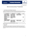
EarthSmart Chiller Options
• Alarm kit – Highly visible strobe light and an alarm beacon indicate chiller
alarm conditions.
• Extended compressor warranty – Warranty extension covers the compressor(s)
only for an additional 2 years. Labor, refrigerant or any other chiller parts are not
included during the extended warranty period.
• Autofill – Reservoir level sensor and solenoid to allow connection to city water
for automatic water make-up. (Not recommended when the chiller is using a
water and Glycol mixture.)
• Process water bypass with valves – Includes process water valves and a
pre-piped, external bypass line with bypass valve for low flow/high delta T
processes which would limit flow through the chiller.
2-14 l Description
SECTION
3
Installation
Unpacking the boxes . . . . . . . . . . . . . . . . . 3-2
Wa r n i n g s a n d c a u t i o n s . . . . . . . . . . . . . . . . 3 - 3
Preparing for installation . . . . . . . . . . . . . . 3-4
Fi l l i n g t h e c h i l l e r . . . . . . . . . . . . . . . . . . . 3 - 7
Checking the refrigerant charge . . . . . . . . . 3-9
Connecting the main power source . . . . . . . 3-10
Checking electrical connections . . . . . . . . . 3-12
Checking pump rotation . . . . . . . . . . . . . . 3-13
Checking the scroll compressor . . . . . . . . . 3-14
Checking the water level gauge . . . . . . . . . 3-14
Adjusting the bypass valve (optional) . . . . . 3-15
Installing alarm indicators (optional) . . . . . 3-16
Installation l 3-1
3
Installation
Making process plumbing connections . . . . . 3-5
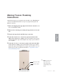
Unpacking the Boxes
EarthSmart Portable Chillers come fully assembled in a single crate. Some aircooled units are shipped without the casters attached. The casters must be
attached during unpacking.
CAUTION: Lifting
EarthSmart Portable Chillers are designed to easily roll on casters. If, for some
reason you need to lift the chiller, take all precautions to avoid personal injury or
damage to the chiller. Lift the chiller using a forklift or hoist with straps that have
been positioned at the chiller’s center of gravity. Do not try to lift the unit
manually.
1 Carefully uncrate the chiller and its components.
2 Remove all packing material, protective paper, tape, and plastic. Compare
contents to the shipping papers to ensure that you have all the parts.
3 Carefully inspect all components to make sure no damage occurred during
shipping. If any damage is found, notify the shipping agent immediately to file
a claim. Check all wire terminal connections, bolts and any other electrical
connections, which may have come loose during shipping. Check for pinched
wires and kinked hoses.
4 Remove the bands holding the chiller on the pallet.
5 With a forklift, lift the chiller high enough to attach the casters, if shipped
unattached. Thread the casters into the threaded plates on each corner of the unit.
6 Record serial numbers and specifications for the chiller in the blanks provided on the back of the User Guide’s title page. This information will be helpful if
you ever need service or parts.
3-2 l Installation
Wa r n i n g s a n d C a u t i o n s
WARNING: Improper installation, operation or
servicing may result in equipment damage or
p e r s o n a l i n j u r y.
This equipment should only be installed, adjusted and serviced by a qualified
technician who is familiar with the construction, operation and potential
hazards of this type of machine.
All wiring, disconnects and fuses should be installed by a qualified electrical
technician in accordance with electrical codes in your region. Always maintain
a safe ground. Do not operate the equipment at power levels other than what is
specified on the machine data plate.
Always protect yourself from hot surfaces when working on the chiller,
especially when working on or around the compressor and condenser. These
devices can reach temperatures up to 160°F {71°C}. Allow these devices to
cool before performing any maintenance or troubleshooting.
CA U T I O N : Ve n t i l a t i o n h a z a r d
The unit requires a clean and well ventilated operating environment. Do not
place anything on top of the unit while operating. Units with top exhaust fans
require unrestricted outlet air flow.
Water-cooled units require a minimum of 1 ft. {30.5 cm} clearance around the
perimeter for serviceability. Conair recommends 2 ft. {60.9 cm} for ease of
servicing. Air-cooled units require a minimum of 2 ft. {60.9 cm} clearance
around the perimeter for serviceability and proper air flow.
WARNING: Refrigerant hazard
Only certified refrigerant technicians should examine and correct problems
involving the refrigerant circuit.
Installation l 3-3
3
Installation
CAUTION: Hot Surfaces
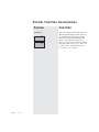
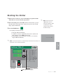
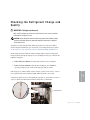
Preparing for Installation
Plan the location for the chiller and prepare the area properly.
Position the chiller as close to the process machine as possible. Place the chiller in
position near the process machine so that coolant lines can be connected from the
process machine to the chiller and back.
Chiller
Process machine
Alternate
locations
Make sure the area where the chiller is installed has:
✐
NOTE: Air-cooled models must
be positioned so that the condenser air inlet is no warmer
than 95°F {35°C} and the condenser air outlet is not blocked
or restricted in any way.
✐
NOTE: Locate air-cooled models away from heat producing
equipment. These items will
affect ambient air conditions
❒ A grounded power source.
Check the chiller’s serial tag for the correct amps, voltage, phase and
cycle. All wiring should be completed by a qualified personnel and
comply with your region’s electrical codes.
❒ Clearance for safe operation and maintenance.
Make sure there is 2 ft. {60.9 cm} of clearance around the chiller for
proper operation. After positioning, lock the casters to prevent the
chiller from moving. For maintenance and servicing, be sure there is
enough clearance to remove all access panels completely.
❒ Available water source. (water-cooled only)
If installing a water-cooled unit, ensure that the water source is
plumbed to the chiller’s installation location. High points in the
plumbing require vent valves; low points require drain valves.
and the performance of the
chiller.
3-4 l Installation
❒ Available water source for Autofill (optional)
If installing a chiller with the optional Autofill function, ensure that the
water source is plumbed to the chiller’s installation location. See
Installation section entitled, Filling the Chiller.
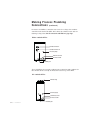
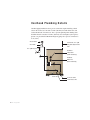
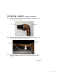
Making Process Plumbing
Connections
Warm fluid from the process equipment enters the chiller at the “From Process”
connection and chilled fluid returns to the process equipment through the “To
Process” connection.
1 Remove the shipping plastic pipe plugs from the female connections on the
back of the EarthSmart Chiller.
2 Make sure the connecting process tubing male pipe threads are clean and
new.
3 Wrap the male pipe threads with Teflon tape or pipe dope.
chiller to the “From Process” tubing. Start by hand until the threads engage
and then tighten with a pipe wrench. Tighten only enough to prevent leaks; do
not over-tighten.
5 Connect the “To Process” valve (factory option) on the back of the chiller
to the “To Process” tubing. Start by hand until the threads engage and then
tighten with a pipe wrench. Tighten only enough to prevent leaks; do not overtighten. If process lines are higher than the chiller, see Appendix E, entitled
Overhead Plumbing Details.
✐
From Process inlet
NOTE: The optional “To”
and “From Process”
valve locations may
To Process outlet
vary depending on the
model.
(Air-cooled model shown)
Installation l 3-5
3
Installation
4 Connect the “From Process” valve (factory option) on the back of the
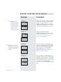
Making Process Plumbing
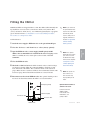
C o n n e c t i o n s (continued)
For water-cooled chillers, connect the water source for cooling to the condenser
water inlet on the back of the chiller, then connect the condenser water outlet for
returning cooling water. Seal all connections with Teflon or pipe dope.
Wa t e r- c o o l e d c h i l l e r
Condenser water in
Condenser water out
Pressure gauge
From Process inlet
To Process outlet
Fill/drain port
Air-cooled chillers do not require condenser water connections. The condenser for
these models will be cooled by an exhaust fan located on top of the chiller.
A i r- c o o l e d c h i l l e r
Exhaust fan(s)
Pressure gauge
From Process inlet
To Process outlet
Fill/drain port
3-6 l Installation
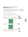
Filling the Chiller
EarthSmart Chillers are shipped without coolant. The chiller is filled manually during installation. Use water as the coolant down to 40°F {4.4°C}. Below 40°F
{4.4°C} and down to 20°F {-6.7°C}, use an industrial grade ethylene or propylene
glycol and water mixture. See Installation section entitled, Filling the Chiller,
Percent Glycol vs. Temperature Chart.
✐
NOTE: If your chiller has
the optional Autofill function, the level switch will
automatically fill the
reservoir, after power is
supplied, with water as
To fill with water:
needed. See Appendix G
1 Attach the water supply to Fill/Drain valve or the optional Autofill port.
entitled, Installing
Autofill (optional).
2 Close the “To Process” and “From Process” valves. (factory optional)
✐
Autofill function overfills
your chiller’s reservoir
the Autofill timer delay
will need to be adjusted.
See Operation section
entitled, Adjusting the
Autofill Timer Delay.
4 Close the Fill/Drain valve.
5 Check the coolant level. When the chiller is turned on the coolant level drops
as it begins to circulate, filling the connected plumbing. Check the coolant
level on the back of the chiller. The coolant level shows on the water level
gauge. Make sure the coolant level is filled to the recommended 3/4 full on the
water level gauge. Turn off the chiller and add more coolant, if needed.
6 Disconnect water hose from Fill/Drain valve. The optional Autofill port does
not need to be disconnected unless the chiller is to be used elsewhere.
Autofill port (optional)
Water level gauge
From Process inlet
NOTE: If the optional
✐
NOTE: The optional “To”
and “From Process”
valve locations may
vary depending on the
model.
Optional Autofill hardware is
available from Conair.
Contact Conair Parts
(800) 458 1960
From outside of the
United States, call:
(814) 437 6861
To Process outlet
Fill/Drain valve
Installation l 3-7
3
chiller to the recommended level of 3/4 full on the water level gauge. If the
chiller is overfilled, the excess water spills out the vent tube. DO NOT
OVERFILL.
Installation
3 Open the Fill/Drain valve or water supply (Autofill option) and fill
Filling the Chiller
(continued)
IMPORTANT: When using a glycol mixture, the EarthSmart Chiller control MUST be
enabled for glycol usage. See Operation section entitled, Glycol Operation Enable/Disable.
✐
IMPORTANT: The EarthSmart Chiller control does NOT monitor the mixture of water to
glycol.
NOTE: When using a glycol mixture, the use of the
optional Autofill function
is not recommended.
To fill with glycol solution:
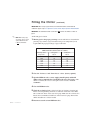
1 Mix the glycol to the proper percentage. Use the table below to determine the
percentage (by volume) of glycol needed for the process temperature (in °F)
required. Mix the proper percentage of glycol with water.
Recommended Percentages of Glycol for
Chilled Water Freeze Protection (by volume)
Discharge water
Temperature
Above 45°F
40°F
35°F
30°F
25°F
20°F
Below 20°F
% Propylene
% Ethylene
Glycol
Glycol
0
0
20
15
25
20
35
30
40
35
45
40
Consult Factory
2 Close the “To Process” and “From Process” valves. (factory optional)
3 Open the Fill/Drain valve or water supply (Autofill option) and the fill
chiller to the recommended level of 3/4 full on the water level gauge. If the
chiller is overfilled, the excess coolant spills out the vent tube. DO NOT
OVERFILL.
4 Close the Fill/Drain valve.
5 Check the coolant level. The coolant level drops as it begins to circulate and
fill the connected plumbing. Check the coolant level on the back of the chiller.
The coolant level shows on the water level gauge. Make sure the coolant level is
filled to the recommended 3/4 full level on the water level gauge. Turn off the
chiller and add more coolant, if needed.
6 Disconnect water hose from Fill/Drain valve.
3-8 l Installation
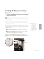
Checking the Refrigerant Charge
WARNING: Refrigerant hazard
Only certified refrigerant technicians should examine and correct problems
involving the refrigerant circuit.
CAUTION: Always disconnect and lock out the main power sources before making
electrical connections. Electrical connections should be made only by a qualified
electrical technician.
All EarthSmart Chillers are fully charged with R-410A refrigerant from Conair.
See Description section entitled, Specifications: EarthSmart ECW and ECA Series,
for required refrigerant charges.
✐
NOTE: Leaving the airpanels off for an
time will cause the
chiller to shut down
❒ Under full load conditions, the refrigerant should be clear (no bubbles).
due to a High Pressure
alarm.
❒ Under low load conditions, when the Hot-gas Bypass valve is operating,
bubbles may be visible in the sight glass. This is normal.
If the charge is low and the unit is under warranty, contact Conair service.
Otherwise have a local, certified refrigeration technician add R-410A refrigerant to
the system.
Sight glass
Installation l 3-9
3
extended period of
Installation
cooled chiller side
Check refrigerant charge while the chiller is running. Check the refrigerant charge
through the sight glass. Remove the bottom left-side panel (depending on model)
and check the sight glass.
C o n n e c t i n g t h e M a i n Po w e r S o u r c e
WARNING: Improper installation, operation or
servicing may result in equipment damage or
p e r s o n a l i n j u r y.
IMPORTANT: Always refer
to the wiring diagrams that
came with your chiller to
locate specific electrical
components. Illustrations in
the User Guide are intended
to be representative only.
This equipment should only be installed, adjusted and serviced by a
qualified technician who is familiar with the construction, operation and
potential hazards of this type of machine.
All wiring, disconnects and fuses should be installed by a qualified electrical technician in accordance with electrical codes in your region. Always
maintain a safe ground. Do not operate the equipment at power levels
other than what is specified on the machine data plate.
WARNING: Electrical hazard
Before performing any work on this equipment, disconnect and lock out
electrical power sources to prevent injury from unexpected energization or
startup.
1 Disconnect and lockout power to the chiller.
2 Open the chiller’s electrical enclosure.
3-10 l Installation
(continued)
C o n n e c t i n g t h e M a i n Po w e r S o u r c e
(continued)
3 Connect the power wires to the terminals. (See the wiring diagrams that
came with your chiller). Route the power cable through the hole in the top of
the electrical enclosure and secure it with an appropriate strain relief.
Terminals
(leads)
4 Check terminal screws to ensure that the wires are secure. Gently tug each
wire, if a wire is loose, use an appropriately-sized screwdriver to tighten the
terminals.
5 Connect the ground wire to the grounding lug.
6 Close the chiller’s electrical enclosure, once all connections have been made.
IMPORTANT: Always refer
to the wiring diagrams that
came with your chiller to
locate specific electrical
components. Illustrations in
the User Guide are intended
to be representative only.
Installation l 3-11
3
Installation
Ground lug
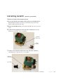
Checking Electrical Connections
WA R N I N G : E l e c t r i c a l H a z a r d
IMPORTANT: Always refer
to the wiring diagrams that
came with your chiller to
locate specific electrical
components. Illustrations in
the User Guide are intended
to be representative only.
IMPORTANT: Conair recommends checking all main
wiring for loose connections
before putting the chiller into
service.
Before performing any work on this item, disconnect and lock out electrical power sources to prevent injury from unexpected energization or
startup.
1 Disconnect and lockout power to the chiller.
Interconnecting
control ribbon
2 Open electrical enclosure.
3 Check the short-to-ground with an ohm meter. Connect an ohm meter to
each of the three terminal screws and to the grounding lug. Test all three for
resistance. The minimum resistance to ground should be 1 megohm. If it resistance is less than 1 megohm there is a leak in the system.
Terminals
(leads)
Ground lug
4 Close the electrical enclosure.
5 Turn the optional disconnect switch to the “On” position and/or apply
main power.
3-12 l Installation
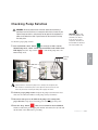
Checking Pump Rotation
WARNING: All wiring, disconnects and fuses should be installed by a
qualified electrical technician in accordance with electrical codes in your
region. Always maintain a safe ground. Do not operate the equipment at
power levels other than what is specified on the the machine serial tag
and data plate.
To check for proper pump rotation:
1 Press and hold the “Start” button
for seven (7) seconds to activate
Manual Pump mode, “nnAn” and the setpoint will flash on the chiller’s dual
LED display. Press the “Stop” button
to turn off the pump and to exit
Manual Pump mode.
IMPORTANT: Always refer
to the wiring diagrams that
came with your chiller to
locate specific electrical
components. Illustrations in
the User Guide are intended
to be representative only.
Ground lug
If pump rotation is reversed, the pump motor is turning in the wrong direction.
Turn off and lock out the main power source. Open the electrical enclosure and
reverse any two leads connecting the main power supply to the chiller.
2 Check for proper pump rotation. Compare the pump rotation from the motor
end to the arrow direction indicator on the pump. (Always clockwise)
3 Disconnect main power to the chiller if the pump is not rotating in the
proper direction, swap any two incoming power wires; reapply main power.
4 Press the “Stop” button
after correct rotation has been established.
Check for leaks in the process piping both internal and external; fix any leaks and
dry the inside of the chiller before proceeding.
Installation l 3-13
3
Installation
Terminals
(leads)
Checking the Scroll Compressor
IMPORTANT: Always refer
to the wiring diagrams that
came with your chiller to
locate specific electrical
components. Illustrations in
the User Guide are intended
to be representative only.
✐
NOTE: If correct pump
WARNING: All wiring, disconnects and fuses should be installed by a
qualified electrical technician in accordance with electrical codes in your
region. Always maintain a safe ground. Do not operate the equipment at
power levels other than what is specified on the the machine serial tag
and data plate.
Pump rotation, if done correctly by reversing leads at the incoming power, will
provide proper rotation for the rest of the three phase motors within the chiller. You
will not be able to determine compressor rotation unless you have refrigeration
gauges.
rotation was established,
the compressor rotation
To check the scroll compressor:
will be correct. Both the
pump and compressor are
phased together during
manufacturing.
1 Inspect the compressor. If the compressor is wired incorrectly, the compressor
LED on the control will illuminate but the compressor will not run. See Appendix
J entitled, Motor Protection.
2 Disconnect main power to the chiller if the pump is not rotating in the
proper direction, swap any two incoming power wires; reapply main power.
Wait three minutes. The compressor should now be running in the proper
direction. See Installation section entitled, Checking Pump Rotation.
C h e c k i n g t h e Wa t e r L e v e l G a u g e
Check the water level gauge on the back of the chiller. If the coolant level below the
3/4 level, see Installation section entitled, Filling the Chiller.
Water level
gauge
3-14 l Installation
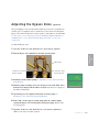
A d j u s t i n g t h e B y p a s s Va l v e
(optional)
The optional Bypass valve is used when the chiller’s process flow is regulated by an
auxiliary piece of equipment, such as a thermolator. Correct water flow through the
Bypass valve must be made before normal operation of the chiller can be established.
See Description section entitled, Specifications: EarthSmart ECW and ECA Series
and Maintenance section entitled, Checking Pump Performance for water flow
requirements.
To adjust the Bypass valve:
1 Close the “To Process” and “From Process” valves (factory optional).
2 Turn the Bypass valve adjustment to the fully opened position.
“From Process” valve
(Factory optional)
“To Process” valve
(Factory optional)
3 Manually start the chiller’s pump. See Installation section entitled, Checking
Pump Rotation.
4 While the pump is running, slowly close the bypass valve until “FSL” (Flow
Switch Loss) is displayed in the chiller’s readout. Once this error is displayed,
the chiller will shutdown.
5 Open the bypass valve slightly and manually restart the pump. See
Installation section entitled, Checking Pump Rotation.
6 If the “FSL” alarm reappears and the pump shuts off, continue slightly
opening the Bypass valve and manually restarting the pump until the alarm
no longer appears.
7 Open the “To Process” and “From Process” valve (factory optional), the
chiller is now ready for normal operation.
Installation l 3-15
3
Installation
Bypass valve
Installing Alarm Indicators
IMPORTANT: Always refer
to the wiring diagrams that
came with your chiller to
locate specific electrical
components. Illustrations in
the User Guide are intended
to be representative only.
(optional)
WARNING: All wiring, disconnects and fuses should be installed by a
qualified electrical technician in accordance with electrical codes in your
region. Always maintain a safe ground. Do not operate the equipment at
power levels other than what is specified on the the machine serial tag
and data plate.
The EarthSmart Chiller is available with optional alarm indicators (a beacon and
strobe light) to alert the user to alarm conditions. Installation of the optional alarm
indicators is required only if they have not been installed from Conair.
To install the optional alarm beacon and strobe light:
1 Disconnect and lockout power to the chiller.
2 Remove the visual and audible alarms from their packaging. (See the wiring
diagrams that came with the alarms)
3 Remove the circular knockouts located at the lower left corner of the electrical enclosure door.
Circular
knock-outs (2)
4 Install the visual alarm in the top knockout and the audible alarm in the
bottom knockout. (See the diagrams that came with the alarms)
3-16 l Installation
(continued)
Installing Alarm Indicators
(optional)
(continued)
5 Connect the alarms to a 24VDC power source from the termination strip in the
electrical enclosure. (See the wiring diagrams that came with the alarms)
Secure all wiring so that the wiring terminations are not under tension when the
electrical enclosure is opened all the way.
IMPORTANT: Always refer
to the wiring diagrams that
came with your chiller to
locate specific electrical
components. Illustrations in
the User Guide are intended
to be representative only.
6 Close the electrical enclosure and apply main power to the chiller to test the
installation.
✐
NOTE: Passive alarms will not activate an alarm output from the chiller’s control.
Installation l 3-17
3-18 l Installation
Operation
Basic control features . . . . . . . . . . . . . . . . 4-4
EarthSmart Chiller control functions . . . . . . . 4-5
SECTION
4
Control function flow charts . . . . . . . . . . . . 4-5
How to navigate the menu tree . . . . . . . . . . 4-5
EarthSmart Chiller menu tree . . . . . . . . . . . 4-6
Control function descriptions . . . . . . . . . . . 4-14
Before starting . . . . . . . . . . . . . . . . . . . . 4-40
Starting the chiller . . . . . . . . . . . . . . . . . 4-41
Stopping the chiller . . . . . . . . . . . . . . . . . 4-42
EarthSmart Chiller sequence of operation . . 4-43
Adjusting setpoint temperature . . . . . . . . . 4-44
Autotuning requirements . . . . . . . . . . . . . . 4-46
Autotuning procedure . . . . . . . . . . . . . . . . 4-46
Changing from fahrenheit to celsius units . . 4-49
Enabling/Disabling display decimal point for
temperature . . . . . . . . . . . . . . . . . . . 4-50
Glycol operation enable/disable . . . . . . . . . 4-51
Adjusting the process variable selection . . . 4-52
Autofill enable/disable (optional) . . . . . . . . 4-53
Setting serial Modbus communication ID . . . 4-54
Adjusting serial baud rate . . . . . . . . . . . . . 4-55
Operation l 4-1
4
Operation
H o w t o u s e t h e s u p e r v i s o r ’s p a s s w o r d . . . . . 4 - 4 5
Setting alarm parameters . . . . . . . . . . . . . 4-56
Adjusting the low pressure inhibit time . . . . 4-56
Adjusting the low pressure delay time. . . . . 4-58
Adjusting the flow switch alarm
inhibit time . . . . . . . . . . . . . . . . . . . . 4-59
Adjusting the flow switch alarm delay time . 4-60
Adjusting the process high alarm setpoint . . 4-61
Adjusting the process high alarm
inhibit time . . . . . . . . . . . . . . . . . . . . 4-62
Adjusting the process high alarm
delay time . . . . . . . . . . . . . . . . . . . . 4-63
Adjusting the process high temperature
shutdown setpoint . . . . . . . . . . . . . . . 4-64
Adjusting the process high temperature
shutdown inhibit time . . . . . . . . . . . . . 4-65
Adjusting the process high temperature
shutdown delay time . . . . . . . . . . . . . 4-66
Adjusting the process low alarm setpoint . . 4-67
Adjusting the process low alarm
inhibit time . . . . . . . . . . . . . . . . . . . . 4-68
Adjusting the process low alarm
delay time . . . . . . . . . . . . . . . . . . . . 4-69
Adjusting the process deviation
high alarm setpoint . . . . . . . . . . . . . . 4-70
4-2
l Operation
Adjusting the process deviation
low alarm setpoint . . . . . . . . . . . . . . . 4-71
Adjusting the process deviation high
alarm inhibit time . . . . . . . . . . . . . . . 4-72
Adjusting the process deviation high
alarm delay time . . . . . . . . . . . . . . . . 4-73
Adjusting the process deviation low
shutdown alarm setpoint . . . . . . . . . . . 4-74
Enabling/Disabling process loop break . . . . 4-75
Adjusting the process loop break timer . . . . 4-76
Adjusting the alarm silence timer . . . . . . . . 4-77
Adjusting the autofill alarm timer . . . . . . . . 4-78
A d j u s t i n g t h e c o m p r e s s o r cy cl e s p e r h o u r
Adjusting the freeze protection shutdown
alarm setpoint . . . . . . . . . . . . . . . . . . 4-80
Operation l 4-3
4
Operation
alarm setpoint. . . . . . . . . . . . . . . . . . . . . 4-79
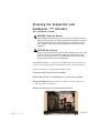
B a s i c C o n t r o l Fe a t u r e s
The EarthSmart Basic Control lets you view the status of the chiller and change
settings.
Scroll Button
Press to scroll through menu lists.
Pressing the “Scroll” button moves you
down the list and saves changes to individual screens.
Dual Display
Dual 4-digit LED screens
shows actual and setpoint process temperatures, alpha-numeric
alarm codes and operation indicators.
Increment/Decrement Buttons
Function Button
Used to increase (+) and/or decrease
(-) the setpoint of a control function.
Used to select different control functions in conjunction with the “Scroll”
button or to save and escape menu
trees during chiller setup.
Alpha-numeric
Alarm Codes
EarthSmart Chiller SX
Alpha-numeric
characters are
displayed in the
setpoint screen
for both process
and alarm conditions during normal operation.
See
Troubleshooting
section for a more
complete listing of
alarms.
Acknowledge Alarm
Button
Press once to silence
the optional audible and
visual alarms. Once the
alarm condition has
been satisfied, press
again to clear the alarm
message.
4-4
Temperature Indicator LEDs
Alarm Indicator LED
Start and Stop Buttons
Illuminated LEDs display the current
units of measurement for temperature.
When an alarm condition is
detected this LED will be illuminated.
Press “Start” to start the
chiller. Press “Stop” to
stop the chiller.
l Operation
Status Indicator
LEDs
Illuminated LED
lights show the
status of the
chiller.
EarthSmart Chiller Control
Functions
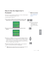
Chiller functions are values that you can set or monitor. Press the “Scroll” button
to access a function within a Menu list until the parameter to be set or monitored
appears in the “Actual” LED display.
✐
NOTE: Grey shaded screens denote supervisor functions. To access the supervisor
screens, see Operation section entitled, Using the Supervisor’s Password.
Control Function Flow Charts
H o w t o N a v i g a t e t h e M e n u Tr e e
To scroll through the Main Status Menu, use the “Scroll” button. To access the
Process Setup, Analog Input Setup, Alarm Setup, Running Time Status, Setup, Test
Mode and Alarm History menu trees, push and release both the “Scroll” and
“Function” buttons together. Once you have selected a menu tree, use the
“Scroll” button the scroll through the screens. Press the “Scroll” button to save
any setting changed within the selected menu. If no changes are made within a
menu tree, the control will automatically return to the Main Status Menu after two
(2) minutes.
Scroll Button
EarthSmart Chiller SX
Function Button
✐
NOTE: Pressing the
“Function” button
within a menu tree will
also save any changes
and return you to the
Main Menu.
✒
TIP: Pressing and holding
the “Scroll” button while
pressing the “Function”
button will increase
menu navigation speed.
Operation l 4-5
4
Operation
The charts beginning on page 4-6 provide a quick summary of the control
functions. For an explanation of each control function, see Operation section
entitled, Control Function Descriptions.
E a r t h S m a r t C h i l l e r M e n u Tr e e
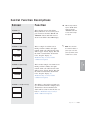
POWER ON
1
8888
8888
2
CH
0.21
3
CHiL
Air
MAIN SCREEN LOOP
4-6
l Operation
4
50
49
5
to.t
50
6
Fr.t
57
7
Ev.t
60
8
St
Run
E a r t h S m a r t C h i l l e r M e n u Tr e e
(continued)
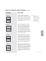
PROCESS SETUP - MENU BRANCH
Pro
CES
10
C.L
mn
11
tun
OFF
12
Out
70
13
Pb
26.0
14
int
15.0
15
dEr
5.0
16
CYC
10
17
On.P
90
18
Hi.L
75
19
Lo.L
20
20
ra.S
21
ra.r
0
22
ra.H
0
off
AF.d
1
24
CCou
4
25
CCin
2
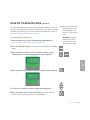
NOTE: Grey shaded screens denote supervisor functions. To access the
supervisor screens, see Operation section entitled, Using the Supervisor’s
Password.
Operation l 4-7
4
23
Operation
✐
9
E a r t h S m a r t C h i l l e r M e n u Tr e e
(continued)
ANALOG INPUT SETUP - MENU BRANCH
✐
26
in
Put
27
CtL
to
28
FL.1
1.0
29
FL.2
1.0
30
FL.3
1.0
31
bi.1
0.0
32
bi.2
0.0
33
bi.3
0.0
NOTE: Grey shaded screens denote supervisor functions. To access the
supervisor screens, see Operation section entitled, Using the Supervisor’s
Password.
4-8
l Operation
E a r t h S m a r t C h i l l e r M e n u Tr e e
(continued)
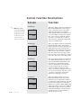
ALARM HISTORY- MENU BRANCH
34
AL
H
35
tCF
HH.MM
36
tSLL
HH.MM
38
39
HH.MM
40
HH.MM
41
HH.MM
42
HH.MM
43
HH.MM
44
HH.MM
45
HH.MM
46
HH.MM
47
HH.MM
48
HH.MM
Operation l 4-9
4
HH.MM
HH.MM
Operation
37
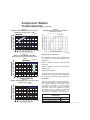
E a r t h S m a r t C h i l l e r M e n u Tr e e
(continued)
ALARM SETUP - MENU BRANCH
✐
NOTE: Grey shaded screens denote
supervisor functions. To access the
49
AL
r
50
LP.I
60
51
LP.d
5
52
FL.I
10
53
FL.d
5
54
H.AL
85
55
H.Ai
10
56
H.Ad
5
57
H.SA
95
58
H.Si
300
59
H.Sd
5
60
L.AL
40
61
L.Ai
10
62
L.Ad
10
63
dE.H
5
64
dE.L
5
65
dE.I
600
66
dE.d
30
67
dL.L
80
68
Lb.e
OFF
69
Lb.t
10
70
ALS
10
71
AF.t
300
72
nccH
10
73
FP
41
supervisor screens, see Operation sec-
tion entitled, Using the Supervisor’s
Password.
4-10
l Operation
E a r t h S m a r t C h i l l e r M e n u Tr e e
(continued)
RUNNING TIME STATUS - MENU BRANCH
74
run
tnn
75
cPr
30.0
76
cPC
20.0
77
LLvC
25.0
78
HgC
25.0
79
PPr
681.0
80
PPC
84.0
81
Fnr
111.0
82
FnC
42.0
4
Operation
Operation l 4-11
E a r t h S m a r t C h i l l e r M e n u Tr e e
(continued)
SETUP - MENU BRANCH
✐
83
Set
uP
84
PaSS
####
85
unit
F
86
deCP
oFF
87
FiL
oFF
88
gLy
no
89
id
1
90
bAud
9600
91
C.r
oFF
92
Hg.r
oFF
93
PP.r
oFF
94
F.r
oFF
95
LL.r
oFF
96
Ld.d
oFF
NOTE: Grey shaded screens denote supervisor functions. To access the
supervisor screens, see Operation section entitled, Using the Supervisor’s
Password.
4-12
l Operation
E a r t h S m a r t C h i l l e r M e n u Tr e e
(continued)
TEST- MENU BRANCH
tE
St
98
in.1
oFF
99
in.2
on
100
in.3
on
101
in.4
oFF
102
in.5
oFF
103
ou.1
oFF
104
ou.2
oFF
Screen 102 and 109 will only be
105
ou.3
oFF
shown when the optional Autofill
106
ou.4
oFF
hardware and axillary board are
107
ou.5
oFF
108
ou.6
oFF
109
ou.7
oFF
installed.
NOTE: Grey shaded screens denote supervisor functions. To access the
supervisor screens, see Operation section entitled, Using the Supervisor’s
Password.
Operation l 4-13
4
Operation
✐
97
Control Function Descriptions
Screen
Function
SCREEN 1 (Read-only)
Once power is turned on, this screen is
displayed for 2 seconds. This screen is a
display test to ensure that all the segments
of the LED display are functioning
properly.
8.8.8.8
8.8.8.8
SCREEN 2 (Read-only)
Software Revision
CH
Once power is turned on and Screen 1 has
been displayed for 2 seconds, this screen
will be displayed for another 2 seconds.
This screen displays the current software
version of the chiller.
V1.01
SCREEN 3 (Read-only)
CHiL
After Screen 1 and 2 have been displayed,
this screen will be shown for an additional
2 seconds. This screen shows the designation of the type of chiller the control is
operating. (Air or H2O)
Air
SCREEN 4 (Read-only)
4-14
l Operation
50
Actual
49
Setpoint
This screen is the top screen of the Main
Status Menu. It displays both actual and
setpoint temperatures. The top screen
shows the Actual temperature of the (To,
From or Average) process coolant. The
bottom screen shows the user-entered
process temperature. Process temperature
ranges are 40° - 70°F {4.4° - 21.1°C}.
Once this screen is displayed, use the (+)
and (-) buttons to change this setting.
Holding down the (+) or (-) buttons causes
this setting to ramp up or down at a faster
rate.
Control Function Descriptions
(continued)
Screen
Function
SCREEN 5 (Read-only)
This screen shows the “To Process” temperature measured by a RTD at the “To
Process” outlet of the chiller.
to.t
50
SCREEN 6 (Read-only)
Fr.t
This screen shows the “From Process”
temperature measured by a RTD at the
“From Process” inlet of the chiller.
57
This screen displays the evaporator leaving
temperature.
Ev.t
60
SCREEN 8 (Read-only)
ST
This screen displays the chiller’s status
mode: RUN, STANDBY, MANUAL,
AUTOTUNE and TEST modes. See
Operation section entitled, Control
Function Descriptions, Screens 10 and 11.
SbY
Operation l 4-15
4
Operation
SCREEN 7 (Read-only)
Control Function Descriptions
✒
TIP: Pressing and hold-
Screen
Function
SCREEN 9
This is the first screen of the Process
Setup Menu tree. To access this screen
press and release both the “Scroll” and
“Function” buttons until this screen is
shown on the chiller’s dual LED display.
ing the “Scroll” button
while pressing the
“Function” button will
increase menu naviga-
Pro
tion speed.
CES
SCREEN 10 (Read-only)
C.L
mn
✐
SCREEN 11
NOTE: Grey shaded
screens denote supervi-
tun
sor functions. To access
the supervisor screens,
see Operation section
entitled, Using the
Supervisor’s Password.
OFF
SCREEN 12 (Read-only)
Out
70
4-16
l Operation
This screen displays the status of the pump
control. (MN = Manual Mode and
AUTO = Automatic Mode) Manual Mode
is only selectable from initial start-up or
Standby Mode by pressing the “Start”
button for 7 seconds. The chiller’s compressor is deactivated in Manual Mode.
This screen is the Autotune On/Off.
Pressing the (+) button on this screen will
turn on Autotune, pressing the (-) will turn
off Autotune. The chiller will only start an
Autotune when the chiller is running and
has a stable load. See Operation section
entitled, Autotuning Requirements and
Autotuning Procedure.
Shows the “On-time” versus “Off-time”
ratio of the Hot-Gas Bypass valve during a
cooling cycle. See Operation section entitled, Control Function Descriptions,
Screen 17.
Control Function Descriptions
(continued)
Screen
Function
SCREEN 13
This screen displays the Process
Proportional Gain. This value is defined
by the Autotune cycle. A higher
Proportional Gain setting will cause a
faster coolant temperature change, but will
use more energy. A lower setting will
cause a slower coolant temperature
change, but requires less energy. Once
this screen is displayed, use the (+) and (-)
buttons to change this setting.
Pb
26.0
SCREEN 14
int
✐
NOTE: Grey shaded
screens denote supervisor functions. To access
the supervisor screens,
see Operation section
entitled, Using the
Supervisor’s Password.
15.0
SCREEN 15
dEr
This is the Process Derivative screen. It is
used to change how fast or slow the control will react to load changes. Use the (+)
and (-) buttons to change this setting.
✐
5.0
NOTE: A cycle includes
the amount of on time
SCREEN 16
CYC
10
This screen displays the duration of the
Hot-gas Bypass valve cycle. Once this
screen is displayed, use the (+) and (-) buttons to change this setting. Conair recommends a 5 to 10 second setting. The range
of this setting is 0 to 120 seconds.
and off time. For example, a 10 second cycle
time equals 5 seconds
on and 5 seconds off of
the Hot-gas Bypass
valve.
Operation l 4-17
4
Operation
This is the Process Integral screen. It is
used to slowly adjust the position of the
proportional gain setting to eliminate offset error. Use the (+) and (-) buttons to
change this setting.
Control Function Descriptions
✐
Screen
Function
SCREEN 17
This screen displays the total allowable
output of the Hot-gas Bypass valve during
one cycle. Once this screen is displayed,
use the (+) and (-) buttons to change this
setting. The range is 0 to 90 percent.
NOTE: Grey shaded
screens denote supervi-
On.P
sor functions. To access
the supervisor screens,
see Operation section
entitled, Using the
Supervisor’s Password.
90
SCREEN 18
Hi.L
✐
75
WARNING: Changing this setting
will effect chiller performance.
This screen displays the Process Setpoint
High Limit. This screen sets the maximum
temperature setpoint of the chiller. Once
this screen is displayed, use the (+) and (-)
buttons to change this setting. The range
is 20° to 70°F {-6.7° to 21.1°C}.
NOTE: Settings for
Screens 18 and 19 can
not overlap.
SCREEN 19
Lo.L
WARNING: To operate
below 40°F {4.4°C},
you must use an
industrial glycol mixture and activate glycol
usage within the chiller
control. See Operation
section entitled, Glycol
Usage Enable/Disable.
20
SCREEN 20
ra.S
OFF
4-18
l Operation
This screen displays the Process Setpoint
Low Limit. This screen sets the minimum
temperature setpoint of the chiller. Once
this screen is displayed, use the (+) and (-)
buttons to change this setting. The range
is 20° to 70°F {-6.7° to 21.1°C}.
This screen displays the Ramp-to Setpoint
On/Off. Turning on this setting will allow
temperature ramping to setpoint by the
rate set on Screen 21. Pressing the (+) button on this screen will turn on the Ramp-to
Setpoint, pressing the (-) will turn off the
Ramp-to Setpoint.
Control Function Descriptions
(continued)
Screen
Function
SCREEN 21
This screen displays the Ramp-to Rate.
When pressing the (+) or (-) buttons to
change the temperature rate at which the
process temperature will achieve setpoint
temperature. Use the (+) or (-) buttons to
change this setting. The range is 0° to
120°F {0° to 67.4°C} degrees per minute.
ra.r
0
SCREEN 22
ra.H
0
1
screens denote supervisor functions. To access
the supervisor screens,
see Operation section
entitled, Using the
Supervisor’s Password.
This screen displays the Ramp-to Setpoint
Hold Back Band. This setting is used to
allow the temperature ramp setting (Screen
21) to achieve a linear temperature profile
by allowing a wider temperature delta.
Once this screen is displayed, use the (+)
and (-) buttons to change this setting. The
range is 0° to 50°F {0° to 28.1°C}.
This screen displays the Autofill Deadband
Delay when the Autofill option is included. Autofill automatically fills the chiller’s
internal reservoir. A normally-open circuit
float switch that must be installed inside
the reservoir indicates to the control that it
is full. See Appendix G entitled, Installing
Autofill (optional). When the float switch
circuit closes it stops the flow of coolant.
This setting delays the shutoff signal and
“overfills” the reservoir to eliminate float
switch “bobbing” that can trigger an alarm
condition. On this screen, use the (+) or (-)
buttons to change this setting. The range is
0 to 60 seconds.
Operation l 4-19
4
AF.d
NOTE: Grey shaded
Operation
SCREEN 23
✐
Control Function Descriptions
✐
Screen
Function
SCREEN 24
This screen displays the Compressor Cutout Deviation Setpoint. This is the temperature deviation below the user-entered setpoint that will cause the chiller’s compressor to shut off. Use the (+) or (-) buttons to
change this setting. The range is 1° to
10°F {0.5° to 5.6°C}.
NOTE: Grey shaded
screens denote supervi-
CCou
sor functions. To access
the supervisor screens,
see Operation section
entitled, Using the
Supervisor’s Password.
✐
4
SCREEN 25
NOTE: Conair recommends the range
CCin
between the Compressor
Cut-in and Cut-out
Deviation Setpoint should
be not less than 6°F
{3.3°C}. This will eliminate short-cycling of the
compressor under light
loads and increases the
life of the compressor.
4-20
l Operation
2
This screen displays the Compressor Cutin Deviation Setpoint. This is the temperature deviation above the user-entered setpoint that will cause the chiller’s compressor to turn on. Use the (+) or (-) buttons to
change this setting. The range is 0° to 5°F
{0° to 2.8°C}.
Control Function Descriptions
Screen
Function
SCREEN 26
This is the first screen of the Input Menu
tree. To access this screen press and
release both the “Scroll” and “Function”
buttons until this screen is shown on the
chiller’s dual LED display.
In
✒
ing the “Scroll” button
while pressing the
“Function” button will
increase menu naviga-
Put
SCREEN 27
CtL
to
1.0
SCREEN 29
FL.2
1.0
This screen displays the Process Control
Input. This screen dictates where the
chiller will read its actual temperature.
(“To Process”, “From Process” or an
“Average” of the two values) Use the (+)
and (-) buttons to choose between the settings.
✐
NOTE: Grey shaded
screens denote supervisor functions. To access
the supervisor screens,
see Operation section
entitled, Using the
Supervisor’s Password.
This screen displays the time period the
chiller’s control will sample the “To
Process” temperature. A long time duration between samples will allow for temperature jumps, a low duration will help
accuracy, but may trigger alarms due to
temperature fluctuations. Use the (+) and
(-) buttons to change this setting. The
range is 0.1 to 10 seconds.
This screen displays the time period the
chiller’s control will sample the “From
Process” temperature. A long time duration between samples will allow for temperature jumps, a low duration will help
accuracy, but may trigger alarms due to
temperature fluctuations. Use the (+) and
(-) buttons to change this setting. The
range is 0.1 to 10 seconds.
Operation l 4-21
4
FL.1
tion speed.
Operation
SCREEN 28
TIP: Pressing and hold-
Control Function Descriptions
✐
Screen
Function
SCREEN 30
This screen displays the time period the
chiller’s control will sample the “Average”
temperature. A long time duration between
samples will allow for temperature jumps,
a low duration will help accuracy, but may
trigger alarms due to temperature fluctuations. Use the (+) and (-) buttons to change
this setting. The range is 0.1 to 10 seconds.
NOTE: Grey shaded
screens denote supervi-
FL.3
sor functions. To access
the supervisor screens,
see Operation section
entitled, Using the
Supervisor’s Password.
1.0
SCREEN 31
bi.1
0.0
✐
NOTE: Temperature offsets are only to be used
in the event the RTD
SCREEN 32
bi.2
temperature does not
match your actual temperature.
0.0
SCREEN 33
bi.3
0.0
4-22
l Operation
(continued)
This screen displays the “To Process”
Temperature Gain Offset. This setting is
used to compensate for the temperature
resistance of the “To Process” RTD connection. Use the (+) and (-) buttons to
change this setting. The range is -1000° to
1000°F {-555.6° to 555.6°C}.
This screen displays the “From Process”
Temperature Gain Offset. This setting is
used to compensate for the temperature
resistance of the “From Process” RTD
connection. Use the (+) and (-) buttons to
change this setting. The range is -1000° to
1000°F {-555.6° to 555.6°C}.
This screen displays the “Average”
Temperature Gain Offset. This setting is
used to compensate for the temperature
resistance of the “Average” RTD connection from the chiller’s evaporator. Use the
(+) and (-) buttons to change this setting.
The range is -1000° to 1000°F {-555.6° to
555.6°C}.
Control Function Descriptions
Screen
Function
SCREEN 34
This is the first screen of the Alarm
History Menu tree. To access this screen
press and release both the “Scroll” and
“Function” buttons until this screen is
shown on the chiller’s dual LED display.
AL
✒
TIP: Pressing and holding the “Scroll” button
while pressing the
“Function” button will
increase menu navigation speed.
H
SCREEN 35 (Read-only)
tCF
HH.MM
HH.MM
SCREEN 37-48 (Read-only)
HH.MM
NOTE: The control will
also flash the number of
power cycles since first
power up until the alarm
condition has occurred.
This is another sample of an alarm screen.
During an alarm condition, the alphanumeric alarm code will be shown in the
chiller’s upper “Actual” display. The time
the alarm occurred will be shown in the
lower “Setpoint” display. See
Troubleshooting section for alarm
condition descriptions.
The chiller’s control will record and store
up to 40 alarms with time stamping. Once
40 alarms have been accumulated, the
alarms will be stored in a first-in, first-out
basis. See Troubleshooting section for
alarm condition descriptions.
Operation l 4-23
4
tSLL
✐
Operation
SCREEN 36 (Read-only)
This is a sample of an alarm screen.
During an alarm condition, the alphanumeric alarm code will be shown in the
chiller’s upper “Actual” display. The time
the alarm occurred will be shown in the
lower “Setpoint” display. See
Troubleshooting section for alarm
condition descriptions.
Control Function Descriptions
✒
TIP: Pressing and holding the “Scroll” button
Screen
Function
SCREEN 49
This is the first screen of the Alarm Setup
Menu tree. To access this screen press and
release both the “Scroll” and “Function”
buttons until this screen is shown on the
chiller’s dual LED display.
AL
while pressing the
“Function” button will
increase menu naviga-
R
tion speed.
✐
NOTE: Grey shaded
screens denote supervisor functions. To access
SCREEN 50
LP.i
the supervisor screens,
see Operation section
entitled, Using the
Supervisor’s Password.
60
SCREEN 51
LP.d
5
SCREEN 52
FL.i
10
4-24
l Operation
This screen displays the Low Pressure
Inhibit Time. This setting is used to adjust
the amount of time after chiller start-up
the Low Pressure Alarm input will be
ignored. This is used so that the chiller can
generate enough coolant pressure to begin
normal operation. Use the (+) and (-) buttons to change this setting. The range is 0
to 120 seconds.
This screen displays the Low Pressure
Delay Time. This setting is used to adjust
the amount of time after the chiller has
detected a Low Pressure Alarm, that its
input will be ignored. This is used to prevent nuisance alarms during Hot-gas
Bypass valve cycling. Use the (+) and (-)
buttons to change this setting. The range
is 0 to 30 seconds.
This screen displays the Flow Switch
Alarm Inhibit Time. This setting is used to
adjust the amount of time after chiller
start-up the Flow Switch Alarm input will
be ignored. This is used so that the chiller
can begin to flow coolant. Use the (+) and
(-) buttons to change this setting. The
range is 0 to 60 seconds.
Control Function Descriptions
(continued)
Screen
Function
SCREEN 53
This screen displays the Flow Switch
Alarm Delay Time. This setting is used to
adjust the amount of time after the chiller
has detected a Flow Switch Alarm, that the
input will be ignored. Use the (+) and (-)
buttons to change this setting. The range is
0 to 30 seconds.
FL.d
5
SCREEN 54
H.AL
85
10
SCREEN 56
H.Ad
5
screens denote supervisor functions. To access
the supervisor screens,
see Operation section
entitled, Using the
Supervisor’s Password.
This screen displays the Process High
Alarm setpoint. This setting is used to
activate a Process High Alarm when the
chiller’s process control input (Screen 27)
coolant temperature exceeds the userentered coolant temperature set at this
screen. This is used to alert the operator to
possible temperature fluctuations that can
effect end product. Use the (+) and (-) buttons to change this setting. The range is 0°
to 85°F {-17.8° to 29.4°C}.
This screen displays the Process High
Alarm Inhibit Time. This setting is used to
adjust the amount of time after chiller
start-up the Process High Alarm input will
be ignored. This is used so that the chiller
can lower the temperature of the coolant
below the temperature set at Screen 54.
Use the (+) and (-) buttons to change this
setting. The range is 0 to 300 seconds.
This screen displays the Process High
Alarm Delay Time. This setting is used to
adjust the amount of time after the chiller
has detected a Process High Alarm, that its
input will be ignored. This is used to eliminate nuisance alarms during startup or
operation. Use the (+) and (-) buttons to
change this setting. The range is 0 to 60
seconds.
Operation l 4-25
4
H.Ai
NOTE: Grey shaded
Operation
SCREEN 55
✐
Control Function Descriptions
✐
Screen
Function
SCREEN 57
This screen displays the Process High
Temperature Shutdown Setpoint. This setting is used to shut down the chiller when
the “To Process” coolant temperature
exceeds the user-entered maximum
coolant temperature set at this screen. This
is used to prevent any damage to the
chiller or end product. Use the (+) and (-)
buttons to change this setting. The range is
50° to 100°F {10° to 37.8°C}.
NOTE: Grey shaded
screens denote supervisor functions. To access
H.SA
the supervisor screens,
see Operation section
entitled, Using the
Supervisor’s Password.
95
SCREEN 58
H.Si
300
SCREEN 59
H.Sd
5
SCREEN 60 (Freeze prevention)
L.AL
40
4-26
l Operation
This screen displays the Process High
Temperature Shutdown Inhibit Time. This
setting is used to adjust the amount of time
after chiller start-up the Process High
Temperature Shutdown input will be
ignored. This is used so that the chiller can
lower the process temperature to normal
operating conditions. Use the (+) and (-)
buttons to change this setting. The range is
0 to 900 seconds.
This screen displays the Process High
Temperature Shutdown Delay Time. This
setting is used to adjust the amount of time
after the chiller has detected a Process
High Shutdown, that its input will be
ignored. This is used to eliminate nuisance
alarms during startup or operation. Use the
(+) and (-) buttons to change this setting.
The range is 0 to 60 seconds.
This screen displays the Process Low
Alarm Setpoint. This setting is used to
activate a Process Low Alarm when the
chiller’s process control input (Screen 27)
temperature falls below the user-entered
minimum coolant temperature set at this
screen. This is used to prevent any damage
to the chiller or end product. Use the (+)
and (-) buttons to change this setting. The
range is 35° to 50°F {-1.7° to 10°C} or if
a glycol mixture is used 15° to 50°F {-9.4°
to 10°C}.
Control Function Descriptions
(continued)
Screen
Function
SCREEN 61
This screen displays the Process Low
Alarm Inhibit Time. This setting is used to
adjust the amount of time after chiller
start-up the Process Low Alarm input will
be ignored. This is used so that the chiller
can raise the temperature of the coolant
above the temperature set at Screen 60.
Use the (+) and (-) buttons to change this
setting. The range is 0 to 180 seconds.
L.Ai
10
SCREEN 62
L.Ad
10
5
Screen 64
dE.L
5
screens denote supervisor functions. To access
the supervisor screens,
see Operation section
entitled, Using the
Supervisor’s Password.
This screen displays the Process Low
Alarm Delay Time. This setting is used to
adjust the amount of time after the chiller
has detected a Process Low Alarm, that its
input will be ignored. This is used to eliminate nuisance alarms. Use the (+) and (-)
buttons to change this setting. The range is
0 to 180 seconds.
This screen displays the Process Deviation
High Alarm Setpoint. This setting is used
to activate a Process Deviation High
Alarm when the chiller’s process control
input (Screen 27) coolant temperature
exceeds the user-entered coolant temperature by the amount set at this screen. This
is used to alert the operator to possible
temperature fluctuations that can effect
end product. Use the (+) and (-) buttons to
change this setting. The range is 0° to
25°F {0° to 14°C}.
This screen displays the Process Deviation
Low Alarm Setpoint. This setting is used
to activate a Process Low Alarm when the
chiller’s process control input (Screen 27)
coolant temperature falls below the userentered coolant temperature by the amount
set at this screen. This is used to alert the
operator to possible temperature fluctuations that can effect end product. Use the
(+) and (-) buttons to change this setting.
The range is 0° to 25°F {0° to 14°C}.
Operation l 4-27
4
dE.H
NOTE: Grey shaded
Operation
SCREEN 63
✐
Control Function Descriptions
✐
Screen
Function
SCREEN 65
This screen displays the Process Deviation
High Alarm Inhibit Time. This setting is
used to adjust the amount of time after
chiller start-up that the Process High
Alarm input will be ignored. This is used
so that the chiller can reduce the temperature of the coolant to within the temperature range set at Screen 63. Use the (+)
and (-) buttons to change this setting. The
range is 0 to 900 seconds.
NOTE: Grey shaded
screens denote supervi-
dE.i
sor functions. To access
the supervisor screens,
see Operation section
entitled, Using the
Supervisor’s Password.
600
SCREEN 66
dE.d
30
SCREEN 67
dL.L
80
SCREEN 68
Lb.e
OFF
4-28
l Operation
This screen displays the Process Deviation
High Alarm Delay Time. This setting is
used to adjust the amount of time after the
chiller has detected a Process Deviation
High Alarm, that its input will be ignored.
This is used so that the chiller’s temperature can resume normal operating conditions. Use the (+) and (-) buttons to change
this setting. The range is 0 to 900 seconds.
This screen displays the Process Deviation
Low Shutdown Alarm Setpoint. This setting is the maximum deviation below the
user-entered low temperature setpoint,
Screen 19. When the coolant falls below
the setpoint by the amount set at this
screen, the chiller automatically shuts
down to avoid freeze damage to the evaporator or process material. Use the (+) and
(-) buttons to change this setting. The
range is 0° to 80°F {0° to 44.9°C}.
This screen displays the Process Loop
Break On/Off. This setting can be used
when the process temperature is higher or
lower than the actual temperature setpoint,
but never exceeds the Process Deviation
High or Low setpoints. When enabled, this
setting will activate a Process Loop Break
Alarm. This setting will always be deactivated when the Ramp-to setting has been
enabled. Use the (+) and (-) buttons to
turn this setting on or off.
Control Function Descriptions
(continued)
Screen
Function
SCREEN 69
This screen displays the Process Loop
Break Time. This setting is used to adjust
the amount of time the Process Loop
Break will wait before alarming. (Screen
68). However, if the actual temperature
reaches the setpoint temperature. The timer
on the delay time will reset. Use the (+)
and (-) buttons to change this setting. The
range is 0 to 900 seconds.
Lb.t
10
SCREEN 70 (optional)
ALS
10
300
SCREEN 72
nCCH
10
screens denote supervisor functions. To access
the supervisor screens,
see Operation section
entitled, Using the
Supervisor’s Password.
This screen displays the Alarm Silence
Timer. This setting is used to adjust the
amount of time after the “Alarm
Acknowledgement” button has been
pressed that the optional beacon and visual
alarms will be de-activated. However, if
the alarm condition has not been satisfied
the optional beacon and visual alarms will
be re-activated. Use the (+) and (-) buttons
to change this setting. The range is 0 to
120 minutes.
This screen displays the Autofill Alarm
Timer. This setting is used to adjust the
amount of time after the control does not
receive an input signal from the chiller’s
reservoir float switch before signaling an
alarm and shutting off Autofill. Use the (+)
and (-) buttons to change this setting. The
range is 0 to 900 seconds.
This screen displays the Compressor
Cycles Per Hour Alarm Point. This setting
is used to adjust the number of compressor
on/off cycles, per hour, in which the control will allow before activating a shutdown alarm. If the number of compressor
On/Off cycles exceeds this setting, the
chiller will shutdown. Use the (+) and (-)
buttons to change this setting. The range
is 2 to 15 cycles/hour.
Operation l 4-29
4
AF.t
NOTE: Grey shaded
Operation
SCREEN 71 (optional)
✐
Control Function Descriptions
Screen
Function
SCREEN 73
This screen displays the Freeze Protection
Shutdown Alarm Setpoint. This setting is
the minimum low temperature setpoint
before the chiller will immediately shut
down to avoid freezing of the process
fluid. Use the (+) and (-) buttons to change
this setting. The range is 35° to 50°F {1.7°
to 10°C} or if a glycol mixture is used,
15° to 50°F {-9.4° to 10°C}.
FP
41
4-30
l Operation
Control Function Descriptions
Screen
Function
SCREEN 74
This is the first screen of the Running
Time Status Menu tree. To access this
screen press and release both the “Scroll”
and “Function” buttons until this screen is
shown on the chiller’s dual LED display.
run
✒
TIP: Pressing and holding the “Scroll” button
tnn
while pressing the
“Function” button will
increase menu naviga-
SCREEN 75 (Read-only)
This screen displays the total run time
(hours x 100) of the compressor.
tion speed.
cPr
30.0
This screen displays the total number of
cycles (cycles x 100) of the compressor.
cPC
20.0
SCREEN 77 (Read-only)
LLvC
This screen displays the total number of
cycles (cycles x 100) of the Liquid Line
Solenoid valve (LLSV).
25.0
Operation l 4-31
4
Operation
SCREEN 76 (Read-only)
Control Function Descriptions
(continued)
Screen
Function
SCREEN 78 (Read-only)
This screen displays the total number of
cycles (cycles x 100) of the Hot-Gas
Bypass valve (HGBP).
HgC
25.0
SCREEN 79 (Read-only)
PPr
This screen displays the total run time
(hours x 100) of the process pump.
681.0
SCREEN 80 (Read-only)
PPC
This screen displays the total number of
cycles (cycles x 100) of the process pump.
84.0
SCREEN 81 (Read-only)
Fnr
This screen displays the total run time
(hours x 100) of the fan. (Air-cooled only)
111.0
SCREEN 82 (Read-only)
FnC
42.0
4-32
l Operation
This screen displays the total number of
cycles (cycles x 100) of the fan. (Aircooled only)
Control Function Descriptions
Screen
Function
SCREEN 83
This is the first screen of the Setup Menu
tree. To access this screen press and
release both the “Scroll” and “Function”
buttons until this screen is shown on the
chiller’s dual LED display.
Set
✒
ing the “Scroll” button
while pressing the
“Function” button will
increase menu naviga-
uP
tion speed.
✐
SCREEN 84
PaSS
210
F
SCREEN 86
deCP
oFF
NOTE: Grey shaded
screens denote supervisor functions. To access
the supervisor screens,
see Operation section
entitled, Using the
Supervisor’s Password.
This screen displays the Units Selection.
This setting is used to change the chiller’s
temperature readout to either Fahrenheit
or Celsius. Use the (+) and (-) buttons to
toggle between the two selections. A corresponding LED on the control panel will
illuminate under the current selection. See
Operation section entitled, Changing from
Fahrenheit to Celsius Units.
This screen displays the Decimal Display
Point for Temperature. This setting is used
to include the decimal point reading for
temperature. Use the (+) and (-) buttons to
toggle between “on” or “off”. See
Operation section entitled, Enabling/
Disabling Display Decimal Point for
Temperature Display.
Operation l 4-33
4
unit
This screen displays the Supervisor’s
Password. This setting is used to gain
access to supervisor screens within the
control. Use the (+) and (-) buttons to
enter the password. The supervisor password is 210. See Operation section entitled, Using the Supervisor’s Password.
Operation
SCREEN 85
TIP: Pressing and hold-
Control Function Descriptions
✐
Screen
Function
SCREEN 87
This screen displays the optional AutoFill
feature “On” or “Off”. Use the (+) and (-)
buttons to toggle between “on” or “off”.
(Additional hardware must be installed for
this feature to be activated. See Appendix
G entitled, Installing Autofill (optional).
NOTE: Grey shaded
screens denote supervi-
FiL
sor functions. To access
the supervisor screens,
see Operation section
entitled, Using the
Supervisor’s Password.
(continued)
oFF
SCREEN 88
gLy
This screen displays the Glycol
Enable/Disable screen. Use the (+) and (-)
buttons to toggle between “yes” or “no”.
See Operation section entitled, Glycol
Operation Enable/Disable.
no
✐
SCREEN 89
NOTE: Ethernet communications will require configuration
id
through the ethernet control
software.
1
SCREEN 90
bAud
9600
4-34
l Operation
This screen displays the Communication
ID. This is used to label where the chiller
will be on a Modbus network. Use the (+)
and (-) buttons to select the Modbus
address. The range is 1 to 247. See
Operation section entitled, Setting Serial
Modbus Communication ID.
This screen displays the Baud Rate. The
Baud Rate can be changed to 2400, 4800,
9600 and 19200 according to you particular communications setup. Use the (+) and
(-) buttons to select the Baud Rate. See
Operation section entitled, Adjusting Baud
Rate.
Control Function Descriptions
Screen
Function
SCREEN 91
This screen displays the Compressor Cycle
Count Reset. This setting is used to clear
the cycle count on screen 76 when replacing the motor starter of the compressor.
Use the (+) and (-) buttons to reset the
compressor cycle count.
C.r
oFF
SCREEN 92
Hg.r
oFF
oFF
SCREEN 94
F.r
screens denote supervisor functions. To access
the supervisor screens,
see Operation section
entitled, Using the
Supervisor’s Password.
This screen displays the Hot-gas Bypass
Valve Cycle Count Reset. This setting is
used to clear the cycle count on screen 78
when replacing the Hot-gas Bypass valve.
Use the (+) and (-) buttons to reset the
Hot-gas Bypass valve cycle count.
This screen displays the Process Pump
Cycle Count Reset. This setting is used to
clear the cycle count on screen 80 when
replacing the process pump. Use the (+)
and (-) buttons to reset the process pump
cycle count.
This screen displays the Fan Cycle Count
Reset. This setting is used to clear the
cycle count on screen 82 when replacing
the fan. Use the (+) and (-) buttons to reset
the fan cycle count.
oFF
Operation l 4-35
4
PP.r
NOTE: Grey shaded
Operation
SCREEN 93
✐
Control Function Descriptions
Screen
Function
SCREEN 95
This screen displays the Liquid Line
Solenoid Valve Cycle Count Reset. This
setting is used to clear the cycle count on
screen 77 when replacing the Liquid Line
Solenoid valve (LLSV). Use the (+) and
(-) buttons to reset the liquid line solenoid
valve cycle count.
LL.r
oFF
SCREEN 96
Ld.d
oFF
4-36
l Operation
(continued)
This screen displays the Load Default.
This setting is used to load all default settings within the Setup Menu Branch
except: run times, PID values, cycle counters, controller option type, chiller type,
Autofill option and Hot-gas Bypass valve
present. Use the (+) and (-) buttons to reset
the load defaults. See Maintenance section
entitled, Reloading Factory Default
Parameters.
Control Function Descriptions
Screen
Function
SCREEN 97
This is the first screen of the Test Menu
tree. To access this screen press and
release both the “Scroll” and “Function”
buttons until this screen is shown on the
chiller’s dual LED display.
tE
in.1
SCREEN 100 (Read-only)
in.3
on
SCREEN 101 (Read-only)
in.4
oFF
“Function” button will
tion speed.
NOTE: Grey shaded
screens denote supervisor functions. To access
the supervisor screens,
see Operation section
entitled, Using the
Supervisor’s Password.
This screen displays the status of the High
Refrigerant Pressure Switch. This switch
is normally-closed and opens when high
pressure (550 PSI {37.9 bar}) is reached
from the compressor during a High
Pressure Alarm. (On = no high pressure,
Off = high pressure)
This screen displays the status of the Low
Refrigerant Pressure Switch. This switch
is normally-closed and opens when low
pressure (110 PSI {7.6 bar}) is reached
from the compressor during a Low
Pressure Alarm. (On = no low pressure,
Off = low pressure)
This screen displays the status of the Fan
Cycling Pressure Switch that enables the
fan on top of an air-cooled chiller to activate depending on the pressure at the outlet of the condenser. This switch is normally-open and closes when pressure at
the outlet of the compressor is above 450
PSI {31.0 bar}. (On = fan on, Off = fan
off when below 320 PSI {22.1 bar})
WARNING: Only a
qualified electrical
technician, trained
in the use of this
equipment and in
avoiding exposure to
voltage hazards,
should perform procedures that require
access to the chiller
while power is on.
Operation l 4-37
4
on
while pressing the
Operation
in.2
ing the “Scroll” button
✐
This screen displays the status of the Flow
Switch. This switch is normally-open and
closes when water is flowing. (On = water
flow, Off = no water flow)
oFF
SCREEN 99 (Read-only)
TIP: Pressing and hold-
increase menu naviga-
St
SCREEN 98 (Read-only)
✒
Control Function Descriptions
✐
NOTE: Screen 102 will
only be shown when the
optional Autofill hardware
Screen
Function
SCREEN 102 (Read-only)
This screen displays the status of the
optional Autofill Switch (float valve) that
enables the chiller to automatically fill its
internal reservoir. This switch is normallyopen and closes when the reservoir is
filled to its capacity. (On = filled to capacity, Off = no water/filling)
in.5
and axillary board are
installed.
✐
NOTE: Grey shaded
screens denote supervisor functions. To access
oFF
SCREEN 103
ou.1
the supervisor screens,
see Operation section
entitled, Using the
Supervisor’s Password.
✐
be in Standby mode to
ou.2
test outputs. To access
Standby mode, press
the “Stop” button on the
This screen tests the functionality of the
Hot-Gas Bypass valve (HGBP). Use the
(+) or (-) buttons to test the valve. The (+)
button will open the valve and keep it
open until the (-) button is pressed.
oFF
SCREEN 104
NOTE: The chiller must
(continued)
This screen tests the functionality of the
process water pump. Use the (+) or (-) buttons to test the pump. The (+) button will
turn on the pump and keep it on until the
(-) button is pressed.
0FF
control panel during
normal operation.
SCREEN 105
ou.3
oFF
4-38
l Operation
This screen tests the functionality of the
compressor. Use the (+) or (-) buttons to
test the compressor. The (+) button will
activate the compressor and keep it on
until the (-) button is pressed.
WARNING: Only qualified technicians with proper training should
test this function. (No alarm conditions or guaranteed off timer.)
Control Function Descriptions
(continued)
Screen
Function
SCREEN 106 (Air-cooled Only)
This screen tests the functionality of the
fan motor. Use the (+) or (-) buttons to test
the fan. The (+) button will activate the fan
and keep it on until the (-) button is
pressed.
ou.4
✐
screens denote supervisor functions. To access
the supervisor screens,
see Operation section
entitled, Using the
Supervisor’s Password.
oFF
SCREEN 107 (Optional)
ou.5
oFF
✐
NOTE: The chiller must
be in Standby mode to
SCREEN 108 (Optional)
ou.6
oFF
SCREEN 109 (Optional)
ou.7
oFF
Standby mode, press
This screen tests the functionality of the
optional audible and visual alarm indicators. Use the (+) or (-) buttons to test the
alarm indicators. The (+) button activates
the alarm indicators and will leave them
on until the (-) button is pressed.
the “Stop” button on the
control panel during
normal operation.
✐
This screen tests the functionality of the
Autofill operation. Use the (+) or (-) buttons to test Autofill. The (+) button will
allow water to flow into the chiller’s reservoir and will leave it flowing until the (-)
button is pressed.
NOTE: Screen 109 will
only be shown when the
optional Autofill hardware and axillary board
are installed.
Operation l 4-39
4
test outputs. To access
Operation
This screen tests the functionality of the
Liquid Line Solenoid valve (LLSV). The
liquid line solenoid valve isolates the high
and low sides of the compressor. Use the
(+) or (-) buttons to test the valve. The (+)
button will open the two halves of the
compressor and will leave them open until
the (-) button is pressed.
NOTE: Grey shaded
Before Starting
Before you start daily operation of the chiller, you need to perform scheduled
preventative maintenance. See Maintenance section entitled, Preventative
Maintenance Schedule.
WA R N I N G : E l e c t r i c a l H a z a r d
Before performing any work on this item, disconnect and/or lock out electrical power
sources to prevent injury from unexpected energization or startup.
Daily maintenance includes:
•
•
•
Checking electrical connections
•
•
Verifying pump discharge pressure
Checking process fluid level in the pump tank
Checking the condenser coil for debris (air-cooled only) or
“Y” Strainer (water-cooled)
Inspect piping for leaks and to ensure all valves are open.
Before starting the chiller be sure to:
•
•
✐
NOTE: All panels must be in
•
Open the “To Process” valve (factory optional) to the full open position.
Open the “From Process” valve (factory optional) to the 3/4 open position. You will need to adjust this valve when the chiller is running to obtain
the desired pump discharge pressure. To find the approximate water flow, see
Description section entitled, Pump Curves.
Open the supply valve if the chiller has the optional Autofill function.
place before starting an aircooled chiller.
From Process valve
(Factory Optional)
To Process valve
(Factory Optional)
4-40
l Operation
Starting the Chiller
1 Make sure the “To Process” valve is in the fully open position and the
“From Process” valve is in the 3/4 open position.
✐
NOTE: Before pressing the
2 Turn on the main power to the chiller. Ensure that the chiller’s optional
disconnect dial is in the ON position. This powers up the control and the
display lights will illuminate.
“Start” button, check to
ensure the Compressor LED is
not flashing. The chiller’s
compressor will not start if
the LED is flashing.
3 Press the START button.
If everything is installed correctly:
• The pump LED will illuminate.
• Compressor contactor, Liquid Line Solenoid valve (LLSV) and
Hot-gas Bypass valve (HGBP) will energize.
• Hot-gas Bypass valve will remain on for three (3) seconds, the
Bypass LED will illuminate.
✐
NOTE: The above description is a normal start-up procedure when the actual process
temperature is above setpoint temperature.
Start Button
Stop Button
Setpoint Adjustment
Buttons
Operation l 4-41
4
Operation
EarthSmart Chiller SX
Stopping the Chiller
1 Press the STOP button.
• The Liquid Line Solenoid valve (LLSV) will de-energize, causing the
compressor to pump down (the compressor pumps refrigerant from the
low side of the compressor to the high side until the low pressure switch
opens).
• The compressor LED will flash and the compressor will shut down once:
- The low pressure cut out limit is reached
• 85 PSI {5.8 bar} for temperature ranges of 40° to 70°F
{4.4° to 21.1°C}
• 50 PSI {3.4 bar} for temperature ranges below 40°F {4.4°C}
{4.4° to 18.3°C}
- If the cut out limit is NOT reached, the compressor will shut off after
30 seconds.
2 Be sure to disconnect and/or lockout the main power if you have stopped the
chiller to perform maintenance or repair.
IMPORTANT: Do not use the main power switch to stop the chiller. Turning off power
to the control and chiller during normal operation prevents the necessary shut down
period.
4-42
l Operation
EarthSmart Chiller Sequence of
Operation (Normal Running Sequence)
1 The chiller is in running mode. The pump and compressor are on (LEDs are
illuminated).
2 The chiller will maintain as close to user-entered setpoint temperature as
possible. When the temperature is above setpoint 100% cooling capacity is in
effect to cool down the process temperature to setpoint temperature.
3 Process temperature will begin to lower to setpoint temperature. Depending
on the PID settings, the Hot-gas Bypass valve (HGBP) will cycle as the process
temperature reaches the setpoint temperature. (The Bypass LED will be illuminated)
the fan(s) will remain on until
the coolant discharge pressure falls below the fan cutout pressure (320 PSI
4 If the process temperature begins to ‘drift’ below the setpoint temperature,
{22.1 bar})
the HGBP will cycle to increase actual temperature to maintain the setpoint
temperature. (Bypass LED will illuminate)
• If actual temperature drops below the setpoint temperature by 4°F
{2.2°C} (for more than four (4) seconds) this will cause the
compressor to start its shut down sequence. Within thirty (30)
seconds the chiller’s compressor will shut off, but the pump will
remain on and functioning.
✐
NOTE: For water-cooled models, the condenser water regulating valve will remain open
until the coolant pressure
• The compressor will start only after the guaranteed off timer has
expired and when the actual temperature is above the setpoint
temperature by 2°F {1.1°C}.
drops below the valve’s setting.
Operation l 4-43
4
NOTE: For air-cooled models,
Operation
✐
A d j u s t i n g S e t p o i n t Te m p e r a t u r e
Use the temperature setpoint to set the temperature of the process coolant that will
exit the chiller at the “To Process” outlet. Depending on the chiller’s Process
Variable Selection, the actual temperature will be measured from the process, to
the process or an average of both. See Operation section entitled, Adjusting the
Process Variable Selection.
To adjust the temperature setpoint:
1 Use the (+) or (-) buttons to increase or decrease the temperature setpoint
from the Main Menu screen. Holding down the (+) or (-) buttons will cause
the setpoint to ramp up or ramp down at a faster rate. The temperature setpoint
will be automatically saved to the chiller’s controller. The chiller will begin to
raise or lower the process temperature, according to your setting.
EarthSmart Chiller SX
Setpoint Adjustment
Buttons
4-44
l Operation
H o w t o U s e t h e S u p e r v i s o r ’s
Pa s s w o r d
✐
NOTE: Entering the password is
required to access all shaded
screens. See Operation section
The supervisor's password must be entered before you can use or make changes to
some screens on the EarthSmart Chiller’s control.
entitled, EarthSmart Chiller
Menu Tree.
To enter the supervisor password:
1 Press and release both the “Scroll” and “Function” buttons together
until the main screen of the Setup Menu (Screen 83) is displayed.
✒
TIP: Pressing and holding the
“Scroll” button while pressing the “Function” button
will increase menu navigation
speed.
2 Press the “Scroll” button until the Password screen (Screen 84) is
displayed.
screen. Holding down the (+) or (-) buttons will cause the number to ramp up
or down at a faster rate. The default supervisory password is 210. Enter this
number to make changes to screens where the supervisor’s password is necessary to use or change a function of the chiller.
4 Press the “Scroll” button to lock in the selection or press the “Function”
button to lock in the selection and exit to the Main Menu.
✐
NOTE: The Supervisor’s Password will be active for ten minutes. After ten minutes the
password must be entered again to alter supervisor password screens.
Operation l 4-45
4
Operation
3 Use the (+) or (-) buttons to increase or decrease the number in the lower
Autotuning Requirements
Autotuning enhances the EarthSmart Chiller control’s ability to govern actual
process temperature in relation to setpoint temperature. It is advised to perform an
Autotune only under normal operating conditions and specifications.
See below for requirements for a successful Autotune:
• The chiller must be in “Stop” mode and under normal load.
• All components of the chiller must be in proper working order.
• The chiller’s process coolant should be 20°F {11.2°C} above or below the
user-entered setpoint. The chiller can Autotune from above the user-entered
setpoint. However, since the chiller controls the process temperature by introducing hot gas into the process, it is recommended to start with a process temperature that is 20°F {-6.7°C} below the user-entered setpoint.
See Troubleshooting section entitled, Autotune Errors, for diagnoses of error codes
during Autotuning.
Autotuning Procedure
Autotuning enhances the EarthSmart Chiller control’s ability to govern actual
process temperature in relation to setpoint temperature. Preloaded parameters are
used to adjust the chiller’s operation to obtain optimum functionality. It is advised
to perform an Autotune only under normal operating conditions and specifications.
✒
TIP: Pressing and holding the
“Scroll” button while pressing the “Function” button
will increase menu navigation
speed.
To perform an Autotune:
1 Adjust the Process Variable Selection. Select the Process Variable the control
will use for Autotuning to optimize performance. See Operation section entitled, Adjusting the Process Variable Selection.
2 Adjust the AutoTune PID cycle time setting. Press and release both the
“Scroll” and “Function” buttons together until the main screen of the Process
Menu (Screen 9) is displayed.
4-46
l Operation
Autotuning Procedure
(continued)
3 Press the “Scroll” button until the Cycle screen (Screen 16) is displayed.
4 Use the (+) or (-) buttons to increase or decrease the amount of cycle time.
The PID settings will cycle within the time set at this screen. A short time setting will improve how closely the chiller will maintain temperature, but it will
reduce the life expectancy of the HGBP valve. A longer time setting will not
control the chiller’s temperature closely, but will extend the life expectancy of
the HGBP valve. Standard default setting is 10 seconds.
5 Press the “Scroll” button to lock in the selection or press the “Function”
button to lock in the selection and exit to the Main Menu.
6 Lower the user-entered setpoint to a minimum of 20°F {11.2°C} below the
7 Press the “Start” button to have the chiller begin lowering the process temperature to the user-entered setpoint.
8 Press the “Stop” button to place the chiller in “Standby” mode, once the
actual temperature is at the user-entered temperature.
9 Increase the user-entered temperature setpoint to a minimum of 20°F
{11.2°C} above the actual process temperature by using the (+) or (-) buttons.
10 Enter the Supervisor’s password within the Setup Menu Branch. See
Operation section entitled, Using Supervisor’s Password.
11 Activate AutoTune. Press and release both the “Scroll” and “Function”
buttons together until the main screen of the Process Menu (Screen 9) is
displayed.
✒
TIP: Pressing and holding the
“Scroll” button while pressing the “Function” button
will increase menu navigation
speed.
Operation l 4-47
4
Operation
actual process temperature by using the (+) or (-) buttons.
Autotuning Procedure
(continued)
12 Once at the Process Menu Branch, press the “Scroll” button until the
Autotune screen (Screen 11) is displayed.
13 Use the (+) or (-) buttons to turn “on” or “off” the Autotune.
14 Press the “Function” button to start the Autotune.
15 Wait for the control to complete the Autotune cycle. During the Autotune
✐
several messages may be shown in the LED display:
NOTE: In the event that an
error is displayed during
Autotuning, see
Troubleshooting section
entitled, Autotune Errors.
✐
NOTE: When performing an
Autotune, the duration for the
chiller to complete one tune
will be at least ten (10)
minutes.
4-48
l Operation
• “tune SetL” - The system is setting the measured values from the
control reference.
• “tune run” - The system is calculating the optimal PID settings.
• “tune done” - The system has completed the Autotune cycle and has
saved the PID parameters.
16 Press the “Stop” button once to return the chiller to normal operation,
after the Autotune cycle is complete.
C h a n g i n g f r o m Fa h r e n h e i t t o
Celsius Units
The EarthSmart Chiller’s display can be programmed to display either Fahrenheit
or Celsius temperature units.
✒
TIP: Pressing and holding the
“Scroll” button while pressing the “Function” button
To select either Fahrenheit or Celsius temperature units:
will increase menu navigation
speed.
1 Enter the Supervisor’s password within the Setup Menu Branch. See
Operation section entitled, Using Supervisor’s Password.
2 Press the “Function” button to save the password entry and exit to the Main
Menu.
3 Press and release both the “Scroll” and “Function” buttons together
until the main screen of the Setup Menu (Screen 83) is displayed.
5 Use the (+) or (-) buttons to toggle between Fahrenheit or Celsius.
6 Press the “Scroll” button to lock in the selection or press the “Function”
button to lock in the selection and exit to the Main Menu.
Operation l 4-49
4
Operation
4 Press the “Scroll” button until the Units screen (Screen 85) is displayed.
Enabling/Disabling Display Decimal
Po i n t f o r Te m p e r a t u r e
✒
TIP: Pressing and holding the
“Scroll” button while press-
The EarthSmart Chiller’s display can be programmed to display temperature units
(Fahrenheit or Celsius) up to one decimal point.
ing the “Function” button
will increase menu navigation
To enable/disable decimal point temperature control readout:
speed.
1 Enter the Supervisor’s password within the Setup Menu Branch. See
Operation section entitled, Using Supervisor’s Password.
2 Press the “Function” button to save the password entry and exit to the Main
Menu.
3 Press and release both the “Scroll” and “Function” buttons together
until the main screen of the Setup Menu (Screen 83) is displayed.
4 Press the “Scroll” button until the Display Decimal Point screen (Screen
86) is displayed.
5 Use the (+) or (-) buttons to turn on or off the decimal point readout.
6 Press the “Scroll” button to lock in the selection or press the “Function”
button to lock in the selection and exit to the Main Menu.
4-50
l Operation
Glycol Operation Enable/Disable
✒
TIP: Pressing and holding the
“Scroll” button while press-
The EarthSmart Chiller’s process coolant can be mixed with glycol for lower
process temperature operation. Proper water to glycol mixture is required for your
specific process temperature. The EarthSmart Chiller does not monitor the percentage of glycol to water. See Installation section entitled, Filling the Chiller.
WARNING: Warranty does NOT include evaporator freeze-up.
ing the “Function” button
will increase menu navigation
speed.
✐
NOTE: The Process Low Alarm
Setpoint must be adjusted
lower when enabling Glycol
To enable/disable glycol operation:
1 Enter the Supervisor’s password within the Setup Menu Branch. See
Operation section entitled, Using Supervisor’s Password.
operation, see Operation section entitled, Adjusting the
Process Low Alarm Setpoint
(L.AL)
2 Press the “Function” button to save the password entry and exit to the Main
Menu.
3 Press and release both the “Scroll” and “Function” buttons together
until the main screen of the Setup Menu (Screen 83) is displayed.
5 Use the (+) or (-) buttons to toggle between “Yes” or “No” for glycol
mixture.
6 Press the “Scroll” button to lock in the selection or press the “Function”
button to lock in the selection and exit to the Main Menu.
Operation l 4-51
4
Operation
4 Press the “Scroll” button until the Glycol screen (Screen 88) is displayed.
A d j u s t i n g t h e P r o c e s s Va r i a b l e
Selection
✒
TIP: Pressing and holding the
“Scroll” button while pressing the “Function” button
will increase menu navigation
The EarthSmart Chiller’s controller allows the user to select where the “Actual”
process temperature will be read from. (“To Process”, “From Process” or
“Average”) Depending upon the specific setup of your process, adjusting this
parameter will provide a more accurate temperature readout.
speed.
To adjust the Process Variable Selection:
1 Press and release both the “Scroll” and “Function” buttons together
until the main screen of the Input Menu (Screen 26) is displayed.
2 Press the “Scroll” button until the Control screen (Screen 27) is displayed.
3 Use the (+) or (-) buttons to toggle between “to”, “fro” or “Avg” selections.
4 Press the “Scroll” button to lock in the selection or press the “Function”
button to lock in the selection and exit to the Main Menu.
✐
NOTE: Conair recommends using the “To Process” process variable selection to protect
against freezing of the coolant. “From Process” and “Average” process variable selections are less accurate and promote nuisance alarms.
4-52
l Operation
Autofill Enable/Disable
(optional)
The optional Autofill feature automatically fills the chiller’s internal reservoir. An
optional Conair-supplied level switch located inside the reservoir indicates whether
the chiller requires more process coolant or when it has been filled to capacity. See
Appendix G entitled, Installing Autofill (optional).
To enable/disable the Autofill option:
1 Enter the Supervisor’s password within the Setup Menu Branch. See
Operation section entitled, Using Supervisor’s Password.
✒
TIP: Pressing and holding the
“Scroll” button while pressing the “Function” button
will increase menu navigation
speed.
IMPORTANT: The optional
Autofill function will not
operate without the level
switch and axillary board.
2 Press the “Function” button to save the password entry and exit to the Main
Menu.
3 Press and release both the “Scroll” and “Function” buttons together
until the main screen of the Setup Menu (Screen 83) is displayed.
5 Use the (+) or (-) buttons to enable or disable the Autofill option.
6 Press the “Scroll” button to lock in the selection or press the “Function”
button to lock in the selection and exit to the Main Menu.
Operation l 4-53
4
Operation
4 Press the “Scroll” button until the Autofill screen (Screen 87) is displayed.
✒
TIP: Pressing and holding the
“Scroll” button while pressing the “Function” button
will increase menu navigation
✐
speed.
Setting Serial Modbus
Communication ID
The EarthSmart Chiller can be configured to communicate over a Modbus network. An optional kit must be installed for the chiller to use the Modbus network.
This optional kit will include: a communications daughter card, internal connecting
harness and a panel mount DB-9 terminal. See Appendix K entitled, EarthSmart
Chiller Modbus Communications, for assigning Modbus address settings.
NOTE: Ethernet communications will require configuration
To set the EarthSmart Chiller’s Modbus address:
through the ethernet control
software.
1 Enter the Supervisor’s password within the Setup Menu Branch. See
Operation section entitled, Using Supervisor’s Password.
2 Press the “Function” button to save the password entry and exit to the Main
Menu.
3 Press and release both the “Scroll” and “Function” buttons together
until the main screen of the Setup Menu (Screen 83) is displayed.
4 Press the “Scroll” button until the Communications screen (Screen 89) is
displayed.
5 Use the (+) or (-) buttons to increase or decrease the address number
assignment. See Appendix K entitled, EarthSmart Chiller Modbus
Communications.
6 Press the “Scroll” button to lock in the selection or press the “Function”
button to lock in the selection and exit to the Main Menu.
4-54
l Operation
7 Restart the chiller for the changes to take effect.
Adjusting Serial Baud Rate
The EarthSmart Chiller’s controller allows the user to select the Baud Rate of their
particular communications network. The selections are 2400, 4800, 9600 and
19200.
✒
TIP: Pressing and holding the
“Scroll” button while pressing the “Function” button
will increase menu navigation
To adjust the Baud Rate selection:
speed.
1 Enter the Supervisor’s password within the Setup Menu Branch. See
Operation section entitled, Using Supervisor’s Password.
2 Press the “Function” button to save the password entry and exit to the Main
Menu.
3 Press and release both the “Scroll” and “Function” buttons together
until the main screen of the Setup Menu (Screen 83) is displayed.
displayed.
5 Use the (+) or (-) buttons to select the Baud Rate of your communications
network. (2400, 4800, 9600 and 19200)
6 Press the “Scroll” button to lock in the selection or press the “Function”
button to lock in the selection and exit to the Main Menu.
7 Restart the chiller for the changes to take effect.
Operation l 4-55
4
Operation
4 Press the “Scroll” button until the Baud Rate screen (Screen 90) is
S e t t i n g A l a r m Pa r a m e t e r s
✐
NOTE: Upon chiller start-up. If
an alarm condition exists,
both the Inhibit and Delay
time settings will be additive.
The EarthSmart Chiller alarm parameters can be set according to your particular
application. Most alarms include an inhibit time and a delay time before actually
indicating an alarm condition. The inhibit time and delay times are used to avoid
repeated alarming that may otherwise allow the chiller to resume normal operating
conditions.
Both times will have to expire
before the chiller’s control will
indicate an alarm condition.
• Inhibit Time - This is the time the chiller’s control will ignore an alarm input
while initially starting the chiller. (Pushing the “Start” button)
• Delay Time - This is the time the chiller’s control will ignore an alarm input
during normal operating conditions of the chiller.
WARNING: Only a qualified electrical technician,
trained in the use of this
equipment should adjust
this setting. Improper
adjustment can be harmful to the compressor's
life span and may void
warranty.
Adjusting the Low Pressure Inhibit
Ti m e ( L P. i )
This setting allows the user to set the time from when a low refrigerant pressure
alarm is detected to when the alarm signals upon chiller start-up. The range for this
setting is 0 to 120 seconds and the standard default setting is 60 seconds.
To adjust the control’s Low Pressure Inhibit Time:
1 Enter the Supervisor’s password within the Setup Menu Branch. See
Operation section entitled, Using Supervisor’s Password.
2 Press the “Function” button to save the password entry and exit to the Main
Menu.
3 Press and release both the “Scroll” and “Function” buttons together
until the main screen of the Alarm Setup Menu (Screen 49) is displayed.
✒
TIP: Pressing and holding the
“Scroll” button while pressing the “Function” button
will increase menu navigation
speed.
(continued)
4-56
l Operation
Adjusting the Low Pressure Inhibit
Ti m e ( L P. i ) ( c o n t i n u e d )
4 Press the “Scroll” button until the Low Pressure Inhibit screen (Screen 50)
is displayed.
5 Use the (+) or (-) buttons to increase or decrease the amount of time delay.
6 Press the “Scroll” button to lock in the selection or press the “Function”
button to lock in the selection and exit to the Main Menu.
4
Operation
Operation l 4-57
WARNING: Only a qualified electrical technician, trained in the use
of this equipment
should adjust this setting. Improper adjustment can be harmful to
the compressor's life
span and may void
warranty.
Adjusting the Low Pressure Delay
Ti m e ( L P. d )
This setting allows the user to set the time from when a low refrigerant pressure
alarm is detected when the chiller is in normal operation. The range for this setting
is 0 to 30 seconds and the standard default setting is 5 seconds.
To adjust the control’s Low Pressure Delay Time:
1 Enter the Supervisor’s password within the Setup Menu Branch. See
Operation section entitled, Using Supervisor’s Password.
2 Press the “Function” button to save the password entry and exit to the Main
Menu.
3 Press and release both the “Scroll” and “Function” buttons together
until the main screen of the Alarm Setup Menu (Screen 49) is displayed.
✒
TIP: Pressing and holding the
“Scroll” button while pressing the “Function” button
will increase menu navigation
speed.
4 Press the “Scroll” button until the Low Pressure Inhibit screen (Screen 51)
is displayed.
5 Use the (+) or (-) buttons to increase or decrease the amount of time delay.
6 Press the “Scroll” button to lock in the selection or press the “Function”
button to lock in the selection and exit to the Main Menu.
4-58
l Operation
Adjusting the Flow Switch Alarm
I n h i b i t Ti m e ( F L . i )
This setting ensures that there is adequate flow through the evaporator before
allowing the compressor to start. The time set at this screen is the time after initial
start-up of the chiller that the control will wait before indicating an alarm and shutting down, if there is no flow. The range for this setting is 0 to 60 seconds and the
standard default setting is 10 seconds.
✒
TIP: Pressing and holding the
“Scroll” button while pressing the “Function” button
will increase menu navigation
speed.
To adjust the control’s Flow Switch Alarm Inhibit Time:
1 Enter the Supervisor’s password within the Setup Menu Branch. See
Operation section entitled, Using Supervisor’s Password.
2 Press the “Function” button to save the password entry and exit to the Main
Menu.
3 Press and release both the “Scroll” and “Function” buttons together
until the main screen of the Alarm Setup Menu (Screen 49) is displayed.
is displayed.
5 Use the (+) or (-) buttons to increase or decrease the amount of time delay.
6 Press the “Scroll” button to lock in the selection or press the “Function”
button to lock in the selection and exit to the Main Menu.
Operation l 4-59
4
Operation
4 Press the “Scroll” button until the Flow Switch Inhibit screen (Screen 52)
Adjusting the Flow Switch Alarm
D e l a y Ti m e ( F L . d )
✒
TIP: Pressing and holding the
“Scroll” button while pressing the “Function” button
will increase menu navigation
This setting ensures that there is adequate flow through the evaporator during normal chiller operation. The time set at this screen is the time the control will wait
before indicating an alarm and shutting down, if there is no flow. The range for this
setting is 0 to 30 seconds and the standard default setting is 5 seconds.
speed.
To adjust the control’s Flow Switch Alarm Delay Time:
1 Enter the Supervisor’s password within the Setup Menu Branch. See
Operation section entitled, Using Supervisor’s Password.
2 Press the “Function” button to save the password entry and exit to the Main
Menu.
3 Press and release both the “Scroll” and “Function” buttons together
until the main screen of the Alarm Setup Menu (Screen 49) is displayed.
4 Press the “Scroll” button until the Flow Switch Delay screen (Screen 53) is
displayed.
5 Use the (+) or (-) buttons to increase or decrease the amount of time delay.
6 Press the “Scroll” button to lock in the selection or press the “Function”
button to lock in the selection and exit to the Main Menu.
4-60
l Operation
Adjusting the Process High Alarm
Setpoint (H.AL)
This setting ensures the chiller does not exceed maximum operational temperature
and alerts the user with a passive alarm to abnormal operating temperatures. The
range for this setting is 0° to 85°F {-17° to 29.4°C} and the standard default setting is 85°F {29.4°C}.
✒
TIP: Pressing and holding the
“Scroll” button while pressing the “Function” button
will increase menu navigation
speed.
To adjust the control’s Process High Alarm Setpoint:
1 Enter the Supervisor’s password within the Setup Menu Branch. See
Operation section entitled, Using Supervisor’s Password.
2 Press the “Function” button to save the password entry and exit to the Main
Menu.
3 Press and release both the “Scroll” and “Function” buttons together
until the main screen of the Alarm Setup Menu (Screen 49) is displayed.
(Screen 54) is displayed.
5 Use the (+) or (-) buttons to increase or decrease the temperature setting.
6 Press the “Scroll” button to lock in the selection or press the “Function”
button to lock in the selection and exit to the Main Menu.
Operation l 4-61
4
Operation
4 Press the “Scroll” button until the Process High Alarm Setpoint screen
Adjusting the Process High Alarm
I n h i b i t Ti m e ( H A . i )
✒
TIP: Pressing and holding the
“Scroll” button while pressing the “Function” button
will increase menu navigation
This setting ensures the chiller will have enough time to lower the process
coolant’s temperature during initial chiller start-up before alerting the user with a
passive alarm. The range for this setting is 0 to 300 seconds and the standard
default setting is 10 seconds.
speed.
To adjust the control’s Process High Alarm Inhibit Time:
1 Enter the Supervisor’s password within the Setup Menu Branch. See
Operation section entitled, Using Supervisor’s Password.
2 Press the “Function” button to save the password entry and exit to the Main
Menu.
3 Press and release both the “Scroll” and “Function” buttons together
until the main screen of the Alarm Setup Menu (Screen 49) is displayed.
4 Press the “Scroll” button until the Process High Alarm Inhibit screen
(Screen 55) is displayed.
5 Use the (+) or (-) buttons to increase or decrease the amount of time delay.
6 Press the “Scroll” button to lock in the selection or press the “Function”
button to lock in the selection and exit to the Main Menu.
4-62
l Operation
Adjusting the Process High Alarm
D e l a y Ti m e ( H A . d )
This setting ensures the chiller will have enough time to lower the process
coolant’s temperature during normal operation before alerting the user with a passive alarm. The range for this setting is 0 to 60 seconds and the standard default
setting is 5 seconds.
✒
TIP: Pressing and holding the
“Scroll” button while pressing the “Function” button
will increase menu navigation
speed.
To adjust the control’s Process High Alarm Delay Time:
1 Enter the Supervisor’s password within the Setup Menu Branch. See
Operation section entitled, Using Supervisor’s Password.
2 Press the “Function” button to save the password entry and exit to the Main
Menu.
3 Press and release both the “Scroll” and “Function” buttons together
until the main screen of the Alarm Setup Menu (Screen 49) is displayed.
(Screen 56) is displayed.
5 Use the (+) or (-) buttons to increase or decrease the amount of time delay.
6 Press the “Scroll” button to lock in the selection or press the “Function”
button to lock in the selection and exit to the Main Menu.
Operation l 4-63
4
Operation
4 Press the “Scroll” button until the Process High Alarm Delay screen
Adjusting the Process High
Te m p e r a t u r e S h u t d o w n S e t p o i n t
(H.SA)
✒
TIP: Pressing and holding the
“Scroll” button while pressing the “Function” button
will increase menu navigation
This setting is the absolute highest temperature the chiller can reach before immediately alarming and shutting down due to abnormal operating temperatures. The
range for this setting is 50° to 100°F {10° to 37.8°C} and the standard default setting is 95°F {35°C}.
speed.
To adjust the control’s Process High Temperature Shutdown Setpoint:
1 Enter the Supervisor’s password within the Setup Menu Branch. See
Operation section entitled, Using Supervisor’s Password.
2 Press the “Function” button to save the password entry and exit to the Main
Menu.
3 Press and release both the “Scroll” and “Function” buttons together
until the main screen of the Alarm Setup Menu (Screen 49) is displayed.
4 Press the “Scroll” button until the Process High Alarm Shutdown Setpoint
screen (Screen 57) is displayed.
5 Use the (+) or (-) buttons to increase or decrease the temperature setting.
6 Press the “Scroll” button to lock in the selection or press the “Function”
4-64
l Operation
button to lock in the selection and exit to the Main Menu.
Adjusting the Process High
Te m p e r a t u r e S h u t d o w n I n h i b i t Ti m e
(H.Si)
This setting ensures the chiller will begin to lower the process coolant’s temperature during initial chiller start-up before alerting the user to a shut down alarm.
The range for this setting is 0 to 900 seconds and the standard default setting is
300 seconds.
✒
TIP: Pressing and holding the
“Scroll” button while pressing the “Function” button
will increase menu navigation
speed.
To adjust the control’s Process High Temperature Shutdown Inhibit Time:
1 Enter the Supervisor’s password within the Setup Menu Branch. See
Operation section entitled, Using Supervisor’s Password.
2 Press the “Function” button to save the password entry and exit to the Main
Menu.
3 Press and release both the “Scroll” and “Function” buttons together
until the main screen of the Alarm Setup Menu (Screen 49) is displayed.
(Screen 58) is displayed.
5 Use the (+) or (-) buttons to increase or decrease the amount of time delay.
6 Press the “Scroll” button to lock in the selection or press the “Function”
button to lock in the selection and exit to the Main Menu.
Operation l 4-65
4
Operation
4 Press the “Scroll” button until the Process High Shutdown Inhibit screen
Adjusting the Process High
Te m p e r a t u r e S h u t d o w n D e l a y Ti m e
(H.Sd)
✒
TIP: Pressing and holding the
“Scroll” button while pressing the “Function” button
will increase menu navigation
This setting ensures the chiller will begin to lower the process coolant’s temperature during normal operation before alerting the user to a shut down alarm. The
range for this setting is 0 to 60 seconds and the standard default setting is 5
seconds.
speed.
To adjust the control’s Process High Temperature Shutdown Delay Time:
1 Enter the Supervisor’s password within the Setup Menu Branch. See
Operation section entitled, Using Supervisor’s Password.
2 Press the “Function” button to save the password entry and exit to the Main
Menu.
3 Press and release both the “Scroll” and “Function” buttons together
until the main screen of the Alarm Setup Menu (Screen 49) is displayed.
4 Press the “Scroll” button until the Process High Shutdown Delay screen
(Screen 59) is displayed.
5 Use the (+) or (-) buttons to increase or decrease the amount of time delay.
6 Press the “Scroll” button to lock in the selection or press the “Function”
4-66
l Operation
button to lock in the selection and exit to the Main Menu.
Adjusting the Process Low Alarm
Setpoint (L.AL)
This setting ensures the chiller does not drop below the minimum operational temperature and alerts the user with a passive alarm to abnormal operating temperatures. The range for this setting is 35° to 50°F {-1.7° to 10°C} or if a glycol mixture is being used, 15° to 50°F {-9.4° to 10°C} and the standard default setting is
40°F {4.4°C}.
✒
TIP: Pressing and holding the
“Scroll” button while pressing the “Function” button
will increase menu navigation
speed.
To adjust the control’s Process Low Alarm Setpoint:
1 Enter the Supervisor’s password within the Setup Menu Branch. See
Operation section entitled, Using Supervisor’s Password.
2 Press the “Function” button to save the password entry and exit to the Main
Menu.
3 Press and release both the “Scroll” and “Function” buttons together
until the main screen of the Alarm Setup Menu (Screen 49) is displayed.
(Screen 60) is displayed.
5 Use the (+) or (-) buttons to increase or decrease the temperature setting.
6 Press the “Scroll” button to lock in the selection or press the “Function”
button to lock in the selection and exit to the Main Menu.
Operation l 4-67
4
Operation
4 Press the “Scroll” button until the Process Low Alarm Setpoint screen
Adjusting the Process Low Alarm
I n h i b i t Ti m e ( L . A i )
✒
TIP: Pressing and holding the
“Scroll” button while pressing the “Function” button
will increase menu navigation
This setting ensures the chiller will begin to raise the process coolant’s temperature
during initial chiller start-up before alerting the user with a passive alarm. The
range for this setting is 0 to 180 seconds and the standard default setting is 10
seconds.
speed.
To adjust the control’s Process Low Inhibit Time:
1 Enter the Supervisor’s password within the Setup Menu Branch. See
Operation section entitled, Using Supervisor’s Password.
2 Press the “Function” button to save the password entry and exit to the Main
Menu.
3 Press and release both the “Scroll” and “Function” buttons together
until the main screen of the Alarm Setup Menu (Screen 49) is displayed.
4 Press the “Scroll” button until the Process Low Alarm Inhibit screen
(Screen 61) is displayed.
5 Use the (+) or (-) buttons to increase or decrease the amount of time delay.
6 Press the “Scroll” button to lock in the selection or press the “Function”
button to lock in the selection and exit to the Main Menu.
4-68
l Operation
Adjusting the Process Low Alarm
D e l a y Ti m e ( L . A d )
This setting ensures the chiller will begin to raise the process coolant’s temperature
during normal operation before alerting the user with a passive alarm. The range
for this setting is 0 to 180 seconds and the standard default setting is 10 seconds.
✒
TIP: Pressing and holding the
“Scroll” button while pressing the “Function” button
will increase menu navigation
To adjust the control’s Process Low Delay Time:
speed.
1 Enter the Supervisor’s password within the Setup Menu Branch. See
Operation section entitled, Using Supervisor’s Password.
2 Press the “Function” button to save the password entry and exit to the Main
Menu.
3 Press and release both the “Scroll” and “Function” buttons together
until the main screen of the Alarm Setup Menu (Screen 49) is displayed.
(Screen 62) is displayed.
5 Use the (+) or (-) buttons to increase or decrease the amount of time delay.
6 Press the “Scroll” button to lock in the selection or press the “Function”
button to lock in the selection and exit to the Main Menu.
Operation l 4-69
4
Operation
4 Press the “Scroll” button until the Process Low Alarm Delay screen
Adjusting the Process Deviation
High Alarm Setpoint (dE.H)
✒
TIP: Pressing and holding the
“Scroll” button while pressing the “Function” button
will increase menu navigation
This setting is used to activate a Process Deviation High Passive Alarm when the
chiller’s actual process temperature exceeds the user-entered temperature by the
value set at this screen. The range for this setting is 0° to 25° {0 to 14° C} and the
standard default setting is 5°F {2.8°C}.
speed.
To adjust the control’s Process Deviation High Alarm Setpoint:
1 Enter the Supervisor’s password within the Setup Menu Branch. See
Operation section entitled, Using Supervisor’s Password.
2 Press the “Function” button to save the password entry and exit to the Main
Menu.
3 Press and release both the “Scroll” and “Function” buttons together
until the main screen of the Alarm Setup Menu (Screen 49) is displayed.
4 Press the “Scroll” button until the Process Deviation High Alarm screen
(Screen 63) is displayed.
5 Use the (+) or (-) buttons to increase or decrease the temperature setting.
6 Press the “Scroll” button to lock in the selection or press the “Function”
button to lock in the selection and exit to the Main Menu.
4-70
l Operation
Adjusting the Process Deviation
Low Alarm Setpoint (dE.L)
This setting is used to activate a Process Deviation High Passive Alarm when the
chiller’s actual process temperature drops below the user-entered temperature by
the value set at this screen. The range for this setting is 0° to 25° {0 to 14° C} and
the standard default setting is 5°F {2.8°C}.
✒
TIP: Pressing and holding the
“Scroll” button while pressing the “Function” button
will increase menu navigation
speed.
To adjust the control’s Process Deviation Low Alarm Setpoint:
1 Enter the Supervisor’s password within the Setup Menu Branch. See
Operation section entitled, Using Supervisor’s Password.
2 Press the “Function” button to save the password entry and exit to the Main
Menu.
3 Press and release both the “Scroll” and “Function” buttons together
until the main screen of the Alarm Setup Menu (Screen 49) is displayed.
(Screen 64) is displayed.
5 Use the (+) or (-) buttons to increase or decrease the temperature setting.
6 Press the “Scroll” button to lock in the selection or press the “Function”
button to lock in the selection and exit to the Main Menu.
Operation l 4-71
4
Operation
4 Press the “Scroll” button until the Process Deviation Low Alarm screen
Adjusting the Process Deviation
H i g h A l a r m I n h i b i t Ti m e ( d E . i )
✒
TIP: Pressing and holding the
“Scroll” button while pressing the “Function” button
will increase menu navigation
This setting ensures the chiller will begin to lower the process coolant’s temperature during initial chiller start-up before alerting the user with a passive alarm. The
range for this setting is 0 to 900 seconds and the standard default setting is 600
seconds.
speed.
To adjust the control’s Process Deviation High Alarm Inhibit Time:
1 Enter the Supervisor’s password within the Setup Menu Branch. See
Operation section entitled, Using Supervisor’s Password.
2 Press the “Function” button to save the password entry and exit to the Main
Menu.
3 Press and release both the “Scroll” and “Function” buttons together
until the main screen of the Alarm Setup Menu (Screen 49) is displayed.
4 Press the “Scroll” button until the Process Deviation High Alarm Inhibit
screen (Screen 65) is displayed.
5 Use the (+) or (-) buttons to increase or decrease the amount of time delay.
6 Press the “Scroll” button to lock in the selection or press the “Function”
button to lock in the selection and exit to the Main Menu.
4-72
l Operation
Adjusting the Process Deviation
H i g h A l a r m D e l a y Ti m e ( d E . d )
This setting ensures the chiller will begin to lower the process coolant’s temperature during normal operation before alerting the user with a passive alarm. The
range for this setting is 0 to 900 seconds and the standard default setting is 30
seconds.
✒
TIP: Pressing and holding the
“Scroll” button while pressing the “Function” button
will increase menu navigation
speed.
To adjust the control’s Process Deviation High Alarm Delay Time:
1 Enter the Supervisor’s password within the Setup Menu Branch. See
Operation section entitled, Using Supervisor’s Password.
2 Press the “Function” button to save the password entry and exit to the Main
Menu.
3 Press and release both the “Scroll” and “Function” buttons together
until the main screen of the Alarm Setup Menu (Screen 49) is displayed.
screen (Screen 66) is displayed.
5 Use the (+) or (-) buttons to increase or decrease the amount of time delay.
6 Press the “Scroll” button to lock in the selection or press the “Function”
button to lock in the selection and exit to the Main Menu.
Operation l 4-73
4
Operation
4 Press the “Scroll” button until the Process Deviation High Alarm Delay
Adjusting the Process Deviation
Low Shutdown Alarm Setpoint
(dL.L)
✒
TIP: Pressing and holding the
“Scroll” button while pressing the “Function” button
will increase menu navigation
This setting is used to activate a Process Deviation Low Alarm and shuts down the
chiller when the actual process temperature drops below the setting at this screen.
The range for this setting is 0° to 80° {0 to 44.9°C} below the user-entered setpoint
and the standard default setting is deliberately set at 80°F {44.9°C}.
speed.
To adjust the control’s Process Deviation Low Shutdown Alarm Setpoint:
1 Enter the Supervisor’s password within the Setup Menu Branch. See
Operation section entitled, Using Supervisor’s Password.
2 Press the “Function” button to save the password entry and exit to the Main
Menu.
3 Press and release both the “Scroll” and “Function” buttons together
until the main screen of the Alarm Setup Menu (Screen 49) is displayed.
4 Press the “Scroll” button until the Process Deviation Low Shutdown Alarm
Setpoint screen (Screen 67) is displayed.
5 Use the (+) or (-) buttons to increase or decrease the temperature setting.
6 Press the “Scroll” button to lock in the selection or press the “Function”
4-74
l Operation
button to lock in the selection and exit to the Main Menu.
Enabling/Disabling Process Loop
Break (Lb.E)
This setting, when enabled, is used to activate a Process Loop Break Shut Down
Alarm when the actual process temperature is slightly higher or lower than the
actual user-entered temperature, however, the actual temperature never exceeds the
Process Deviation High or Low setpoints.
✒
TIP: Pressing and holding the
“Scroll” button while pressing the “Function” button
will increase menu navigation
speed.
To enable the Process Loop Break:
1 Enter the Supervisor’s password within the Setup Menu Branch. See
Operation section entitled, Using Supervisor’s Password.
2 Press the “Function” button to save the password entry and exit to the Main
Menu.
3 Press and release both the “Scroll” and “Function” buttons together
until the main screen of the Alarm Setup Menu (Screen 49) is displayed.
(Screen 68) is displayed.
5 Use the (+) or (-) buttons to turn the Process Loop Break on or off.
6 Press the “Scroll” button to lock in the selection or press the “Function”
button to lock in the selection and exit to the Main Menu.
Operation l 4-75
4
Operation
4 Press the “Scroll” button until the Process Loop Break On/Off screen
Adjusting the Process Loop Break
Ti m e r ( L b . t )
✒
TIP: Pressing and holding the
“Scroll” button while pressing the “Function” button
will increase menu navigation
speed.
This setting is used to adjust the amount of time after the chiller’s control has
detected Process Loop Break until it activates a Process Loop Break Shutdown
Alarm. The timer will automatically reset when the chiller’s actual process temperature reaches the user-entered process temperature. The range for this setting is 0 to
900 seconds and the standard default setting is 10 seconds.
To adjust the Process Loop Break Timer:
1 Enter the Supervisor’s password within the Setup Menu Branch. See
Operation section entitled, Using Supervisor’s Password.
2 Press the “Function” button to save the password entry and exit to the Main
Menu.
3 Press and release both the “Scroll” and “Function” buttons together
until the main screen of the Alarm Setup Menu (Screen 49) is displayed.
4 Press the “Scroll” button until the Process Loop Break Timer screen
(Screen 69) is displayed.
5 Use the (+) or (-) buttons to increase or decrease the amount of time delay.
6 Press the “Scroll” button to lock in the selection or press the “Function”
button to lock in the selection and exit to the Main Menu.
4-76
l Operation
A d j u s t i n g t h e A l a r m S i l e n c e Ti m e r
(ALS)
This setting is used to adjust the amount of time after the “Alarm
Acknowledgment” button has been pressed that the optional beacon and visual
alarm indicators will be deactivated. If, after the “Alarm Acknowledgment”
button has been pressed and the alarm condition has not been satisfied, it will
re-activate. The range for this setting is 0 to 120 minutes and the standard default
setting is 10 minutes.
✒
TIP: Pressing and holding the
“Scroll” button while pressing the “Function” button
will increase menu navigation
speed.
To adjust the Alarm Silence Timer:
1 Enter the Supervisor’s password within the Setup Menu Branch. See
Operation section entitled, Using Supervisor’s Password.
2 Press the “Function” button to save the password entry and exit to the Main
Menu.
3 Press and release both the “Scroll” and “Function” buttons together
4 Press the “Scroll” button until the Alarm Silence Timer screen (Screen 70)
is displayed.
5 Use the (+) or (-) buttons to increase or decrease the temperature setting.
6 Press the “Scroll” button to lock in the selection or press the “Function”
button to lock in the selection and exit to the Main Menu.
Operation l 4-77
4
Operation
until the main screen of the Alarm Setup Menu (Screen 49) is displayed.
A d j u s t i n g t h e A u t o f i l l A l a r m Ti m e r
( A F. t ) ( o p t i o n a l )
✒
TIP: Pressing and holding the
“Scroll” button while pressing the “Function” button
will increase menu navigation
This setting is used to adjust the amount of time after the chiller’s control has not
received an input signal from the optional reservoir float switch before activating an
alarm. The range for this setting is 0 to 900 seconds and the standard default setting
is 300 seconds.
speed.
To adjust the Autofill Alarm Timer:
1 Enter the Supervisor’s password within the Setup Menu Branch. See
Operation section entitled, Using Supervisor’s Password.
2 Press the “Function” button to save the password entry and exit to the Main
Menu.
3 Press and release both the “Scroll” and “Function” buttons together
until the main screen of the Alarm Setup Menu (Screen 49) is displayed.
4 Press the “Scroll” button until the Autofill Alarm Timer screen (Screen 71)
is displayed.
5 Use the (+) or (-) buttons to increase or decrease the amount of time delay.
6 Press the “Scroll” button to lock in the selection or press the “Function”
button to lock in the selection and exit to the Main Menu.
4-78
l Operation
A d j u s t i n g t h e C o m p r e s s o r C y cl e s
per Hour Alarm Setpoint (nCCH)
This setting is used to adjust the number of compressor On/Off cycles per hour the
chiller’s control will allow before activating a shutdown alarm. The one hour time
frame is started when the user presses the “Start” button and refreshes every hour
after startup. The range for this setting is 2 to 15 cycles/hour and the standard
default setting is 10 cycles per hour.
✒
TIP: Pressing and holding the
“Scroll” button while pressing the “Function” button
will increase menu navigation
speed.
To adjust the Compressor Cycles per Hour Alarm Setpoint:
1 Enter the Supervisor’s password within the Setup Menu Branch. See
Operation section entitled, Using Supervisor’s Password.
2 Press the “Function” button to save the password entry and exit to the Main
Menu.
3 Press and release both the “Scroll” and “Function” buttons together
until the main screen of the Alarm Setup Menu (Screen 49) is displayed.
Setpoint screen (Screen 72) is displayed.
5 Use the (+) or (-) buttons to increase or decrease the amount of cycles per
hour.
6 Press the “Scroll” button to lock in the selection or press the “Function”
button to lock in the selection and exit to the Main Menu.
Operation l 4-79
4
Operation
4 Press the “Scroll” button until the Compressor Cycles per Hour Alarm
Adjusting the Freeze Protection
Shutdown Alarm Setpoint (FP)
✒
TIP: Pressing and holding the This setting is used to adjust the minimum low temperature setpoint before the
chiller will immediately shut down to avoid freezing of the process fluid. The
range for this setting is 35° to 50°F {1.7° to 10°C} or if a glycol mixture is used,
ing the “Function” button
will increase menu navigation 15° to 50°F {-9.4° to 10°C}. The standard default setting is 41°F {5°C}.
“Scroll” button while press-
speed.
To adjust the Freeze Protection Shutdown Alarm Setpoint:
1 Enter the Supervisor’s password within the Setup Menu Branch. See
Operation section entitled, Using Supervisor’s Password.
2 Press the “Function” button to save the password entry and exit to the Main
Menu.
3 Press and release both the “Scroll” and “Function” buttons together
until the main screen of the Alarm Setup Menu (Screen 49) is displayed.
4 Press the “Scroll” button until the Freeze Protection Shutdown Alarm
Setpoint screen (Screen 73) is displayed.
5 Use the (+) or (-) buttons to turn increase or decrease the temperature setting.
6 Press the “Scroll” button to lock in the selection or press the “Function”
button to lock in the selection and exit to the Main Menu.
4-80
l Operation
SECTION
5
Maintenance
Maintenance features. . . . . . . . . . . . . . . . . 5-2
Wa r n i n g s a n d c a u t i o n s . . . . . . . . . . . . . . . . 5 - 3
Preventative maintenance schedule . . . . . . . 5-4
Checking electrical connections . . . . . . . . . . 5-6
Cleaning the brazed plate evaporator
o r w a t e r- c o o l e d c o n d e n s e r . . . . . . . . . . 5 - 7
C l e a n i n g t h e a i r- c o o l e d c o n d e n s e r . . . . . . . 5 - 1 0
Checking the refrigerant charge
and quality . . . . . . . . . . . . . . . . . . . . 5-11
Checking the hot-gas bypass
valve operation . . . . . . . . . . . . . . . . . 5-14
Cleaning the evaporator and
condenser “Y” strainer . . . . . . . . . . . . 5-16
C h e c k i n g o r cl e a n i n g t h e f l o w s w i t c h . . . . . 5 - 2 0
Checking reservoir level . . . . . . . . . . . . . . 5-22
Checking pump performance . . . . . . . . . . . 5-23
Reloading factory default parameters . . . . . 5-24
Maintenance l 5-1
5
Maintenance
C h e c k i n g t h e c o m p r e s s o r ’s o i l l e v e l . . . . . . 5 - 1 2
M a i n t e n a n c e Fe a t u r e s
Conair EarthSmart Series Chillers need regular, scheduled maintenance for peak
performance.
To maintain the best performance of the chiller, it must be cleaned and inspected
regularly. Maintenance includes a daily, monthly, and semi-annual schedule. See
Maintenance section entitled, Preventative Maintenance Schedule and Appendix B
entitled, Maintenance Log.
Use this maintenance schedule as a guide. You may need to shorten the time of the
maintenance schedule, depending on how often you use the chiller. Among the features that require preventative maintenance are:
•
•
•
•
•
•
•
•
•
5-2 l Maintenance
The refrigerant system.
Electrical cables, terminals and control lights.
The condenser, condenser filter strainer inlets.
Caster locks.
Temperature and pressure readings.
Process fluid level.
Energy-efficiency.
Evaporator, filter strainer at evaporator and condenser inlets.
Cooling water treatment system (if used).
Wa r n i n g s a n d C a u t i o n s
WARNING: Improper installation, operation or
servicing may result in equipment damage or
p e r s o n a l i n j u r y.
This equipment should only be installed, adjusted and serviced by a qualified
technician who is familiar with the construction, operation and potential
hazards of this type of machine.
All wiring, disconnects and fuses should be installed by a qualified electrical
technician in accordance with electrical codes in your region.
WARNING: Electrical Hazard
Before performing any work on this item, disconnect and lock out electrical
power sources to prevent injury from unexpected energization or startup. Be
sure that power to the chiller is OFF when doing any maintenance on the
chiller. Follow all safety rules when performing any maintenance on this equipment.
CAUTION: Hot Surfaces
Always protect yourself from hot surfaces when working on the EarthSmart
Chiller, especially when working on or around the compressor and condenser.
These devices can reach up to 160°F {71°C}. Allow these devices to cool
before performing any maintenance or troubleshooting.
Only a certified refrigerant technicians should examine and correct problems
involving the refrigerant circuit.
Maintenance l 5-3
5
Maintenance
WARNING: Refrigerant Hazard
Preventative Maintenance Schedule
To maintain the best performance, follow the maintenance
schedule and record information in the Maintenance Log in
Appendix B.
Daily, or as often as needed
❒ Checking process fluid level in the pump tank
Check the process fluid level in the water level gauge on the back of the
chiller. If low, see Installation section entitled, Filling the Chiller.
❒
Verifying pump discharge pressure
While the pump is running, check that the pump pressure gauges (not
included) are within range. To change the pressure open or close the “To
Process” valve.
❒
Inspecting piping for leaks
Check to see that pipes are not leaking. Look for standing water on the floor
or inside the chiller cabinet, tighten and/or clean as necessary.
❒
Inspecting the condenser coil for debris (Air-cooled only)
Remove the wire mesh side panel and filter in front of the condenser coil.
Remove any debris from the coils and clean the fan blades. See Maintenance
section entitled, Cleaning the Air-cooled Condenser.
IMPORTANT: Conair recommends that the wire terminations be tightened during any servicing of
the chiller.
Weekly, or as often as needed
❒ Checking temperature and pressure readings
Check that the temperature displays on the control screen, on the condenser
inlet and outlet and pressure gauges (not included) on the condenser piping
indicate normal operation.
5-4 l Maintenance
❒
Checking efficiency
Review the performance data on the Maintenance Log found in
Appendix B. If you notice a decrease in efficiency over time, check all heat
transfer surfaces of the evaporator and condenser for fouling. Clean as needed.
❒
Checking refrigerant site glass
There should not be any bubbles in the sight glass unless when the Hot-gas
Bypass valve (HGBP) is energized. See Maintenance section entitled,
Checking Refrigerant Charge.
❒
Checking reservoir level
Check the water level gauge on the back of the chiller. If fluid level is low,
fill. See Maintenance section entitled, Checking Reservoir Level.
❒
Cleaning the Evaporator and Condenser “Y” strainer
See Maintenance section entitled, Cleaning the Evaporator and
Condenser “Y” Strainer.
Preventative Maintenance Schedule
Monthly
❒ Inspecting cooling water treatment system
If your chiller uses a cooling water treatment system, maintain proper chemical levels and follow the recommendations of your water treatment specialist.
Otherwise, change water in the reservoir tank monthly to decrease water
hardness. See Appendix D entitled, Water Quality Control.
❒
Cleaning
Wipe all external surfaces to maintain finish.
❒
Inspecting condenser
Check the condenser for adequate airflow or water flow. Check the condenser surface for dirt and clogging. If dirt or clogs are present, clean the condenser. See Maintenance sections entitled, Cleaning the Evaporator or
Water-cooled Condenser and Cleaning the Air-cooled Condenser. Check,
clean and replace the filter at the air inlet of the air-cooled condenser coil
inspect and clean the fan blades, as needed.
❒
Inspecting the control panel
Check for loose wires, burned contacts, and signs of overheated wires.
Check that all panel lights illuminate. See Maintenance section entitled,
Checking Electrical Connections.
❒
Checking refrigerant charge
With the compressor running, check the sight glass between the receiver and
evaporator for proper refrigerant condition. See Maintenance section entitled,
Checking Refrigerant Charge.
❒
Cleaning the Evaporator and Condenser “Y” strainer
See Maintenance section entitled, Cleaning the Evaporator and
Condenser “Y” Strainer.
Annually
❒ Cleaning the evaporator or air-cooled condenser
See Maintenance sections entitled, Cleaning the Brazed Plate Evaporator or
Water-cooled Condenser and Cleaning the Air-cooled Condenser.
❒
Check refrigerant piping
Verify that no oil is present on fittings or cabinet. Wipe clean and check
charge/operation of circuit.
Maintenance l 5-5
5
Checking electrical connections, amps and volts
Make sure electrical connections are properly seated. See Maintenance section entitled, Checking Electrical Connections. Check fan, compressor,
pump, amps and volts by checking the data tag located inside the electrical
enclosure. See Description section entitled, Specifications: EarthSmart ECW
and ECA Series.
Maintenance
❒
To maintain the best performance, follow the maintenance
schedule and record information in the Maintenance Log in
Appendix B.
Checking Electrical Connections
WARNING: Electrical Hazard
Before performing any work on this item, disconnect and lock out electrical
power sources to prevent injury from unexpected energization or startup. Be
sure that power to the chiller is OFF when doing any maintenance on the
chiller. Follow all safety rules when performing any maintenance on this
equipment.
WARNING: Improper installation, operation or
servicing may result in equipment damage or
p e r s o n a l i n j u r y.
IMPORTANT: Always refer
to the wiring diagrams that
came with your chiller to
locate specific electrical
components. Illustrations in
the User Guide are intended
to be representative only.
This equipment should only be installed, adjusted and serviced by a qualified
technician personnel who is familiar with the construction, operation and potential
hazards of this type of machine.
All wiring, disconnects and fuses should be installed by a qualified electrical technician in accordance with electrical codes in your region.
1 Be sure the main power is disconnected and/or the chiller’s optional disconnect
switch is locked out. Always disconnect and lockout the main power source before
opening the unit for servicing.
2 Open the electrical enclosure.
3 Inspect all wires and connections. Look for loose wires, burned contacts and
signs of over-heated wires. Compare the wiring to the wiring diagrams you
received with your chiller. Have a qualified electrician make any necessary repairs
or replacements.
4 Close the electrical enclosure door.
5 Inspect the exterior power cords. Cords should not be crimped, exposed or rubbing against the frame. If the main power cord runs along the floor, make sure it is
positioned where it could not rest in pooling water or could not be ran over and cut
by wheels or casters.
5-6
l Maintenance
C l e a n i n g t h e B r a z e d P l a t e E va p o r a t o r
o r Wa t e r- c o o l e d C o n d e n s e r
Minerals and other contaminants produce deposits, scales, slime or algae on heat
transfer surfaces exposed to water. Fouled surfaces result in decreased cooling capacity. Implement a water treatment program to slow the fouling.
CAUTION: Hot Surfaces
Always protect yourself from hot surfaces when working on the chiller, especially when working on or around the compressor and condenser. These
devices can reach up to 160°F {71°C}. Allow these devices to cool before
performing any maintenance or troubleshooting.
Water quality should be maintained at a pH level of 7.4, but not less than 6.0 for
proper heat exchanger life.
✐
✐
To clean the brazed plate adapter:
1 Disconnect and lock out main power.
2 Remove the chiller’s side panels.
3 Prepare a 5% solution of Phosphoric acid or Oxalic acid and water. Do not
heat the acid solution.
4b If cleaning the condenser, close the condenser inlet and outlet valves and
drain the condenser piping.
5 If cleaning the evaporator, disconnect the pump from the heat exchanger.
✐
NOTE: These connections
may vary depending on the
model you have purchased.
Be sure to see the labeling
on your particular unit.
Install a cap in the opening of the heat exchanger where the pump was connected.
5b If cleaning the condenser, disconnect piping to the condenser. Install a cap in
the opening of the condenser where the piping was connected.
(continued)
Maintenance l 5-7
5
drain reservoir. See Installation section entitled, Drain Connection.
NOTE: EarthSmart Chiller
models 1.5, 3 and 5 have
Tube-in-Tube style heat
exchangers made with copper and steel. Follow recommended guidelines of the
cleaning solution supplier
for mixtures based upon the
severity of fouling.
Maintenance
4 If cleaning the evaporator, shut the “To” and “From Process” valves and the
NOTE: All brazed plate heat
exchangers are copper and
stainless steel.
C l e a n i n g t h e B r a z e d P l a t e E va p o r a t o r
o r Wa t e r- c o o l e d C o n d e n s e r ( c o n t i n u e d )
CAUTION: Hot Surfaces
Always protect yourself from hot surfaces when working on the chiller,
especially when working on or around the compressor and condenser. These
devices can reach up to 160°F {71°C}. Allow these devices to cool before
performing any maintenance or troubleshooting.
✐
✐
✐
6 Remove RTD from bottom of evaporator or condenser.
NOTE: All brazed plate heat
exchangers are copper and
stainless steel.
NOTE: EarthSmart Chiller
models 1.5, 3 and 5 have
Tube-in-Tube style heat
exchangers made with copper and steel. Follow recommended guidelines of the
cleaning solution supplier
for mixtures based upon the
severity of fouling.
7 For the evaporator, connect 1/2-inch tubing to the 1/2-inch connections of the
heat exchanger. SEE below to install customer supplied chemical pump and solution fitted to the heat exchanger.
7b For the condenser, remove 3/8 inch heat exchanger plug to drain. Connect as
shown below and back flush. SEE below to install customer supplied chemical
pump and solution fitted to the heat exchanger.
8 Back-flush the solution through the heat exchanger and the chiller.
9 Flush the heat exchanger and the chiller piping with fresh water after
cleaning.
NOTE: These connections
may vary depending on the
model you have purchased.
Be sure to see the labeling
on your particular unit.
10 Reconnect the chiller pump to the heat exchanger. Remove the cap in the heat
exchanger and reconnect the hose from the pump.
Heat
Exchanger
1/2 inch connection on
outside of chiller cabinet
Valve
1/2 inch
plugs
To Process
connection
5-8 l Maintenance
Acid
solution
Fluid circuit
Pump
(continued)
C l e a n i n g t h e B r a z e d P l a t e E va p o r a t o r
o r Wa t e r- c o o l e d C o n d e n s e r ( c o n t i n u e d )
CAUTION: Hot Surfaces
Always protect yourself from hot surfaces when working on the chiller,
especially when working on or around the compressor and condenser. These
devices can reach up to 160°F {71°C}. Allow these devices to cool before
performing any maintenance or troubleshooting.
11 Re-install the RTD for the evaporator or condenser.
12 For the evaporator, open the “To Process” and “From Process” valves
(factory optional)
12b For the condenser, open the condenser inlet and outlet valves.
✐
NOTE: These connections
may vary depending on the
model you have purchased.
Be sure to see the labeling
on your particular unit.
13 Replace the chiller’s side panels.
14 Reapply main power.
5
Maintenance
Maintenance l 5-9
C l e a n i n g t h e A i r- C o o l e d C o n d e n s e r
WARNING: Electrical Hazard
Before performing any work on this item, disconnect and lock out electrical
power sources to prevent injury from unexpected energization or startup. Be
sure that power to the chiller is OFF when doing any maintenance on the
chiller. Follow all safety rules when performing any maintenance on this
equipment.
CAUTION: Hot Surfaces
Always protect yourself from hot surfaces when working on the chiller,
especially when working on or around the compressor and condenser. These
devices can reach up to 160°F {71°C}. Allow these devices to cool before
performing any maintenance or troubleshooting.
Replacement air filters are
available from Conair.
Contact Conair Parts
(800) 458 1960
From outside of the
United States, call:
(814) 437 6861
The air-cooled condenser can accumulate dirt and clog quickly if it is ran in a dusty
or dirty environment. A clogged condenser increases refrigerant discharge pressure,
lowers performance, and may cause the fan motor(s) and compressor to overheat.
To clean the air-cooled condenser:
1 Disconnect and lockout power to the chiller.
2 Remove the wire mesh air filter that is located on the side of the chiller by
lifting up and out.
✐
NOTE: Conair recommends
cleaning the air-cooled
chiller’s exhaust fan blades
when cleaning the filter.
Air filter
3 Inspect the coils. Use a flashlight to check between coil surfaces.
4 Clean the dirty coils with a soft brush or vacuum.
5 Flush with cool water or a commercial coil cleaner that is compatible with
aluminum alloys. Conair recommends spraying the coil cleaner from inside the
chiller’s cabinet.
5 Inspect and clean the air filter. Replace as needed.
CAUTION: Wear eye protection.
5-10 l Maintenance
If you use compressed air to clean the equipment, you must wear eye protection and observe all OSHA and other safety regulations pertaining to the
use of compressed air.
Checking the Refrigerant Charge and
Quality
WARNING: Refrigerant hazard
Only certified refrigerant technicians should examine and correct problems
involving the refrigerant circuit.
CAUTION: Always disconnect and lock out the main power sources before making
electrical connections. Electrical connections should be made only by a qualified
electrical technician.
All chillers are fully charged with R-410A refrigerant from Conair. Your chiller’s
model nameplate identifies the type and amount of total refrigerant charge required.
See Description section entitled, Specifications: EarthSmart ECW and ECA Series.
Check refrigerant charge while the chiller is running under normal load. Check the
refrigerant charge through the sight glass. Use a flashlight, if necessary, and check the
liquid-line sight glass:
•
Under full load conditions, the refrigerant should be clear (no bubbles).
•
Under low load conditions, when the Hot-Gas Bypass valve (HGBP) is
operating, bubbles may be visible in the sight glass. This is normal.
A refrigerant quality label is located within the sight glass. A green label is normal. A
yellow or dark brown label indicates that the refrigerant is contaminated.
Sight glass
Maintenance l 5-11
5
Maintenance
If the charge is low and the chiller is under warranty, contact Conair service; or have a
local, certified refrigeration technician add R-410A refrigerant to the system.
C h e c k i n g t h e C o m p r e s s o r ’s O i l L e v e l
(Models ECW 7.5 and higher)
WARNING: Electrical Hazard
Before performing any work on this item, disconnect and lock out electrical
power sources to prevent injury from unexpected energization or startup. Be
sure that power to the chiller is OFF when doing any maintenance on the
chiller. Follow all safety rules when performing any maintenance on this
equipment.
CAUTION: Hot Surfaces
Always protect yourself from hot surfaces when working on the chiller,
especially when working on or around the compressor and condenser. These
devices can reach up to 160°F {71°C}. Allow these devices to cool before
performing any maintenance or troubleshooting.
During normal operation, the EarthSmart compressor oil level should be between 1/8
and 1/2 full, and when at rest or in Stop mode the oil level should be 1/8 to 3/4 full.
To check the compressor’s oil level:
1 Disconnect and lockout power to the chiller.
2 Remove the left-side panel. (As viewed from the control)
3 Locate the compressor, it is positioned in the upper compartment of the chiller’s
cabinet.
4 Locate the compressor’s sight glass. The sight glass is positioned on the bottom
of the compressor.
5-12 l Maintenance
(continued)
C h e c k i n g t h e C o m p r e s s o r ’s O i l L e v e l
(Models ECW 7.5 and higher) (continued)
Sight glass
5 Check the compressor’s oil level. If no oil is visible, use a flashlight and look for
bubbles rising in the sight glass. This may be an indication of liquid refrigerant in
the compressor or the compressor is overfilled with oil.
oil level is below the recommended limits or if bubbles are visible in the sight
glass.
7 Replace the right-side panel.
8 Reapply main power to the chiller.
IMPORTANT: Attempting to service the compressor will void any warranty.
Maintenance l 5-13
5
Maintenance
6 Contact Conair Service or a certified refrigerant technician if the compressor
C h e c k i n g t h e H o t - g a s B y p a s s Va l v e
Operation
WARNING: Electrical Hazard
Before performing any work on this item, disconnect and lock out electrical
power sources to prevent injury from unexpected energization or startup. Be
sure that power to the chiller is OFF when doing any maintenance on the
chiller. Follow all safety rules when performing any maintenance on this
equipment.
CAUTION: Hot Surfaces
Always protect yourself from hot surfaces when working on the chiller,
especially when working on or around the compressor and condenser. These
devices can reach up to 160°F {71°C}. Allow these devices to cool before
performing any maintenance or troubleshooting.
IMPORTANT: Always refer
to the wiring diagrams that
came with your chiller to
locate specific electrical
components. Illustrations in
the User Guide are intended
to be representative only.
The Hot-gas Bypass valve (HGBP) is used as a heating element to maintain the userentered setpoint temperature of the EarthSmart Chiller’s process fluid. The HGBP
valve allows refrigerant to bypass the chiller’s condenser where heat is removed.
Refrigerant is introduced to the evaporator to heat the process fluid providing consistent chiller temperatures. If the HGBP valve is closed, 100% cooling capacity is used
to reduce or maintain temperature.
To check the Hot-gas Bypass valve’s functionality:
1 Remove the left-side panel. (As viewed from the control)
5-14 l Maintenance
(continued)
C h e c k i n g t h e H o t - g a s B y p a s s Va l v e
O p e r a t i o n (continued)
2 Locate the TXV and follow the refrigerant piping to the evaporator. The Hotgas Bypass line is the piping running down from the upper portion of the chiller’s
cabinet between the evaporator and TXV.
Hot-gas
Bypass valve
Hot-gas
Bypass line
IMPORTANT: Always refer
to the wiring diagrams that
came with your chiller to
locate specific electrical
components. Illustrations in
the User Guide are intended
to be representative only.
and off indicating that the valve is being energized. There should also be a
‘click’ from the valve and refrigerant flowing (hissing sound) to the evaporator.
4 Measure the temperature of the Hot-gas Bypass line as the valve is energized.
If the valve is functioning properly, there should be a noted temperature rise from
when the valve is off to when it is energized.
5 Verify that the Hot-gas Bypass valve coil is functioning correctly and that
power is reaching the coil when the bypass LED is energized, if no sign of
refrigerant flow or temperature change has been detected. See the chiller’s electrical wiring diagram.
IMPORTANT: Attempting to service the Hot-gas Bypass valve will
void any warranty.
6 Contact Conair Service or a certified refrigerant technician to replace the
Hot-gas Bypass valve, if the valve is damaged or not functioning properly.
Maintenance l 5-15
5
Maintenance
3 During operation the bypass LED on the chiller’s control panel will pulse on
C l e a n i n g t h e E va p o r a t o r a n d
Condenser “Y” Strainer
( A i r a n d Wa t e r- c o o l e d )
WARNING: Electrical Hazard
Before performing any work on this item, disconnect and lock out electrical
power sources to prevent injury from unexpected energization or startup. Be
sure that power to the chiller is OFF when doing any maintenance on the
chiller. Follow all safety rules when performing any maintenance on this
equipment.
CAUTION: Hot Surfaces
Always protect yourself from hot surfaces when working on the chiller, especially when working on or around the compressor and condenser. These
devices can reach up to 160°F {71°C}. Allow these devices to cool before
performing any maintenance or troubleshooting.
The EarthSmart Chiller’s “Y” strainer(s) can accumulate dirt and clog quickly if it is
ran in a poor water quality environment; which will cause poor chiller performance.
To clean the evaporator “Y” strainer (Air and Water-cooled):
1 Disconnect and/or lockout power to the chiller.
2 Shut off the “To Process” and “From Process” valves (factory optional).
3 Open the Fill/Drain valve. Close the valve when the water level gauge on the
back of the chiller reads half full.
4 Remove the left-side panel. (As viewed from the control)
(continued)
5-16 l Maintenance
C l e a n i n g t h e E va p o r a t o r a n d
C o n d e n s e r “ Y ” S t r a i n e r (continued)
( A i r a n d Wa t e r- c o o l e d )
5 Locate the evaporator “Y” strainer at the discharge of the Evaporator pump.
Evaporator
“Y” strainer
6 Remove the center plug from the cap to drain any water in the strainer, by using
an appropriately-sized pipe wrench.
7 Remove the strainer from the strainer housing.
9 Re-install the strainer and strainer cap. Properly seal all piping with approved
Replacement “Y” strainers are
available from Conair.
Teflon tape or pipe dope.
IMPORTANT: Check to ensure the strainer is properly seated before applying the strainer
cap. Crushing of the strainer can occur if it is not fully inserted back into the strainer
housing.
Contact Conair Parts
(800) 458 1960
From outside of the
United States, call:
(814) 437 6861
10 Check to ensure no leaking has occurred before returning the chiller to normal
operation.
(continued)
Maintenance l 5-17
5
necessary.
Maintenance
8 Inspect the strainer. Check for holes tears or filter blinding, clean or replace as
C l e a n i n g t h e E va p o r a t o r a n d
C o n d e n s e r “ Y ” S t r a i n e r (continued)
( Wa t e r- c o o l e d o n l y )
WARNING: Electrical Hazard
Before performing any work on this item, disconnect and lock out electrical
power sources to prevent injury from unexpected energization or startup. Be
sure that power to the chiller is OFF when doing any maintenance on the
chiller. Follow all safety rules when performing any maintenance on this
equipment.
CAUTION: Hot Surfaces
Always protect yourself from hot surfaces when working on the chiller,
especially when working on or around the compressor and condenser. These
devices can reach up to 160°F {71°C}. Allow these devices to cool before
performing any maintenance or troubleshooting.
The EarthSmart Chiller’s “Y” strainer can accumulate dirt and clog quickly if it is ran
in a poor water quality environment; which will cause poor chiller performance.
To clean the condenser “Y” strainer (Water-cooled only):
1 Disconnect and/or lockout power to the chiller.
2 Shut off water flow to the condenser inlet and outlet valves (factory optional).
3 Remove the right-side panel. (As view from the control)
4 Locate the “Y” strainer at the inlet of the condenser.
(continued)
5-18 l Maintenance
C l e a n i n g t h e E va p o r a t o r a n d
C o n d e n s e r “ Y ” S t r a i n e r (continued)
( Wa t e r- c o o l e d o n l y )
5 Locate the evaporator “Y” strainer at the discharge of the condenser.
Evaporator
“Y” strainer
6 Remove the center plug from the cap to drain any water in the strainer, by using
an appropriately-sized pipe wrench.
necessary.
9 Re-install the strainer and strainer cap. Properly seal all piping with approved
Teflon tape or pipe dope.
IMPORTANT: Check to ensure the strainer is properly seated before applying the strainer
cap. Crushing of the strainer can occur if it is not fully inserted back into the strainer
housing.
Replacement “Y” strainers are
available from Conair.
Contact Conair Parts
(800) 458 1960
From outside of the
United States, call:
(814) 437 6861
10 Check to ensure no leaking has occurred before returning the chiller to normal
operation.
Maintenance l 5-19
5
8 Inspect the strainer. Check for holes tears or filter blinding, clean or replace as
Maintenance
7 Remove the strainer from the strainer housing.
Checking or Cleaning the Flow
Switch
WARNING: Electrical Hazard
Before performing any work on this item, disconnect and lock out electrical
power sources to prevent injury from unexpected energization or startup. Be
sure that power to the chiller is OFF when doing any maintenance on the
chiller. Follow all safety rules when performing any maintenance on this
equipment.
CAUTION: Hot Surfaces
Always protect yourself from hot surfaces when working on the chiller,
especially when working on or around the compressor and condenser. These
devices can reach up to 160°F {71°C}. Allow these devices to cool before
performing any maintenance or troubleshooting.
The EarthSmart Chiller’s flow switch can accumulate dirt and deposits and give
inaccurate water flow readouts in a poor water quality environment. Periodically
check the flow switch when Flow Switch Failure (FSL) alarms become more apparent.
To check and/or clean the flow switch:
1 Disconnect and/or lockout power to the chiller.
2 Shut off the “To Process” and “From Process” valves (factory optional).
3 Open the Fill/Drain valve. Close the valve when the water level gauge on the
back of the chiller reads half full.
4 Remove the left-side panel. (As view from the control)
(continued)
5-20 l Maintenance
Checking or Cleaning the Flow
S w i t c h (continued)
5 Remove the two (2) screws at the top of the switch. Ensure to mark the position
of the circuit selection switch located on top of the switch, “NO” (normally-open).
Flow switch
6 Unscrew the switch from the piping with an appropriately-sized wrench. Note
the arrow direction on the side of the switch before removing, the switch must be
installed back into this location.
7 Inspect and clean the switch by tapping the paddle on a hard surface. This will
switch into the piping with proper flow direction.
9 Re-install electrical hardware to the switch and fill the reservoir and open the
“To Process” and “From Process” valves (factory optional).
10 Reapply main power to the chiller to test the switch.
Replacement flow switches
are available from Conair.
Contact Conair Parts
(800) 458 1960
From outside of the
United States, call:
(814) 437 6861
Maintenance l 5-21
5
8 Apply Teflon tape or pipe dope to the switch threads and re-insert THE
Maintenance
loosen debris in the upper housing so the paddle will move again and/or spray with
lubricant to free up moving parts, or replace as necessary.
Checking Reservoir Level
WARNING: Electrical Hazard
Before performing any work on this item, disconnect and lock out electrical
power sources to prevent injury from unexpected energization or startup. Be
sure that power to the chiller is OFF when doing any maintenance on the
chiller. Follow all safety rules when performing any maintenance on this
equipment.
Check the fluid level in the reservoir. The read-out in the sight glass on the back of
the chiller should be 3/4 full.
To manually fill the reservoir:
1 Disconnect and/or lockout power to the chiller.
2 Locate the Fill/Drain valve on the back of the chiller and open the valve.
3 Refill the reservoir. Monitor the level using the water level indicator on the back
of the chiller. Because the EarthSmart Chiller can use either pure water or a glycol/
water mixture, make sure you are adding the correct fluid for your application. See
Installation section entitled, Filling the Chiller.
Autofill port
Water level indicator
Fill/Drain valve
IMPORTANT: When using a glycol mixture, the use of the optional Autofill function is not
recommended.
5-22 l Maintenance
C h e c k i n g P u m p Pe r f o r m a n c e
CAUTION: Hot Surfaces
Always protect yourself from hot surfaces when working on the chiller,
especially when working on or around the compressor and condenser.
These devices can reach up to 160°F {71°C}. Allow these devices to cool
before performing any maintenance or troubleshooting.
Checking your EarthSmart Chiller’s pump performance ensures that the motor pump
is operating properly. Proper operation of the motor pump maintains correct water
pressure to your process, which allows cooling of your system.
To check motor pump performance:
1 Check the difference between the pump discharge pressure at the “To
Process connection (inline pressure gauge not included) and the pressure at
the inlet of the evaporator.
2 Plot the discharge pressure from the “To Process” connection on the pump
curve that is specific to your model chiller, see Description section entitled,
Pump Curves. The pump curves will indicate the flow of the process fluid in
gallons per minute.
4 Check pump impeller performance, if the pump motor’s rotation is
correct, by shutting off the “To Process” valve (factory optional) during
operation. Note the “To Process” pressure from the pump and reference
this number (0 gpm) on the pump curve, see Description section entitled,
Pump Curves. If there is no significant difference between the pump curve pressure and the actual pressure, the pump impeller is operating properly. If there is
a difference of 5 psig or more between the actual pressure and the pump curve
readout, replace the pump. See Troubleshooting section entitled, Replacing
Pump Components.
Replacement motor pumps
and water pressure gauges
are available from Conair.
Contact Conair Parts
(800) 458 1960
From outside of the
United States, call:
(814) 437 6861
Maintenance l 5-23
5
will be running at 80% or higher of its full load amp (FLA) rating. If the
pump’s FLA rating is below 80%, there may be low process fluid flow. See
Installation section entitled, Checking Pump Rotation.
NOTE: When using the
motor pump in the pump
tank, the “From Process”
water pressure is determined by the height
above the inlet. Add 1 psi
for every 2.31 ft {70.4
cm} above the inlet.
Maintenance
3 Check the pump motor’s full load amp usage. Typically, the pump motor
✐
R e l o a d i n g Fa c t o r y D e fa u l t
Pa r a m e t e r s
✒
TIP: Pressing and holding the
“Scroll” button while pressing the “Function” button
will increase menu navigation
speed.
Reloading the factory default parameters should only be performed when all other
troubleshooting methods have been attempted. Reloading default parameters will
reset all parameters except: Run Times, PID Values, Cycle Counters, Controller
Option Type, Chiller Type, Autofill Option and Hot-gas Bypass valve present.
To reload all factory default parameters:
1 Enter the Supervisor’s password within the Setup Menu Branch. See
Operation section entitled, Using Supervisor’s Password.
2 Press the “Function” button to save the password entry and exit to the Main
Menu.
3 Press and release both the “Scroll” and “Function” buttons together
until the main screen of the Setup Menu (Screen 82) is displayed.
4 Press the “Scroll” button until the Load Default screen (Screen 95) is
displayed.
5 Use the (+) or (-) buttons to turn the Load Default on or off.
6 Press the “Scroll” button to lock in the selection or press the “Function”
button to lock in the selection and exit to the Main Menu.
7 Error code “0297” will be shown in the chiller’s display. This is normal after
resetting factory defaults.
8 Restart the chiller’s control to resume normal operation.
5-24 l Maintenance
SECTION
Tr o u b l e s h o o t i n g
6
Before beginning . . . . . . . . . . . . . . . . . . . . 6-2
Identifying the cause of a problem . . . . . . . 6-2
A few words of caution
. . . . . . . . . . . . . . 6-3
TROUBLESHOOTING
Chiller problems . . . . . . . . . . . . . . . . . . . . 6-4
Autotuning errors
. . . . . . . . . . . . . . . . . . 6-6
Pa s s i v e a l a r m s . . . . . . . . . . . . . . . . . . . . . 6 - 8
Shut down alarms . . . . . . . . . . . . . . . . . . 6-13
Additional alarms . . . . . . . . . . . . . . . . . . 6-20
R e p l a c i n g t h e RT D . . . . . . . . . . . . . . . . . . 6 - 2 2
Removing pump components . . . . . . . . . . . 6-23
Replacing the contactor . . . . . . . . . . . . . . 6-24
6
Troubleshooting
Tr o u b l e s h o o t i n g l 6 - 1
Before Beginning
You can avoid most problems by following the recommended installation, operation and maintenance procedures outlined in this User Guide. If you have a problem, this section will help you determine the cause and tell you how to fix it.
Before you begin troubleshooting:
❑ Find any wiring, piping and assembly diagrams that were shipped with
your equipment. These are the best references for correcting a problem. The
diagrams will note any custom features or options not covered in this User
Guide.
❑ Check that you have manuals for other equipment connected in the system.
Troubleshooting may require investigating other equipment attached to, or
connected with the chiller.
Identifying the Cause of a Problem
The Troubleshooting section covers problems directly related to the operation and
maintenance of the EarthSmart Chiller.
Types of conditions you may see include control problems (not lighting, or lighting
and not running) and alarm conditions (passive or shut down).
When the alarm light is displayed:
1 Note the alarm and press the “Acknowledge Alarm” button once to silence
the optional audible and visual alarms and display the alarm message, if
still active.
2 Find the error message in the diagnostics table of this Troubleshooting
section. Use information provided to diagnose and resolve the cause of the
alarm.
3 Note that, after correcting the problem, pressing the “Acknowledge
Alarm” button a second time will clear the alarm. If the alarm reappears,
the cause has not been resolved.
6 - 2 l Tr o u b l e s h o o t i n g
A Fe w Wo r d s o f C a u t i o n
WARNING: Improper installation, operation or
servicing may result in equipment damage or
p e r s o n a l i n j u r y.
This equipment should only be installed, adjusted and serviced by a
qualified technician who is familiar with the construction, operation and
potential hazards of this type of machine.
All wiring, disconnects and fuses should be installed by a qualified
electrical technician in accordance with electrical codes in your region.
WARNING: Electrical Hazard
Before performing any work on this item, disconnect and lock out
electrical power sources to prevent injury from unexpected energization
or startup. Be sure that power to the chiller is OFF when doing any
maintenance on the chiller. Follow all safety rules when performing any
maintenance on this equipment.
CAUTION: Hot Surfaces
Always protect yourself from hot surfaces when working on the chiller,
especially when working on or around the compressor and condenser.
These devices can reach up to 160°F {71°C}. Allow these devices to cool
before performing any maintenance or troubleshooting.
WARNING: Refrigerant Hazard
Only a certified refrigerant technician should examine and correct
problems involving the refrigerant circuit.
6
Troubleshooting
Tr o u b l e s h o o t i n g l 6 - 3
Chiller Problems
Look here if the control panel is not lit, or if the power is on and the
EarthSmart Chiller will not run.
Symptom
Possible cause
Solution
The control is not lit and the
chiller is not working.
Power is not reaching the chiller.
Check the power cord and plug. Make
sure the cord and plug are properly
connected.
Ensure that the optional disconnect
switch is in the “On” position.
Check fuses, breakers and power
supplies. Replace or reset as necessary.
The control is not lit and
there is no alarm condition.
The compressor hums, but
does not run.
Interconnecting control ribbon cable is
loose or disconnected.
Resecure control cable, ensure the main
board’s LED is flashing.
The correct power is not reaching the
unit.
Check the voltage specification on the
chiller nameplate. See Description section entitled, Specifications: EarthSmart
ECW and ECA Series.
There is a problem with the control
panel.
The control panel may have failed.
Contact Conair Service.
The input voltage is incorrect.
Check the main supply voltage. It must
be within 10% of the nameplate rating.
There is a phase loss and/or the compressor’s contactor is welded shut.
Check the phase-to-phase voltages.
Check the phase continuity through the
compressor contactor.
Check the wiring at the compressor
Replace or repair as needed.
The motor starter protector is damaged.
Replace the motor starter, see Appendix
J entitled, Motor Protection.
6 - 4 l Tr o u b l e s h o o t i n g
Chiller Problems
Symptom
Possible cause
Solution
The compressor LED on the
control panel is lit, but the
compressor is not running.
The compressor’s overload has been
tripped.
Reset and properly adjust the
compressor overload.
The compressor contactor is damaged or
defective.
Replace the contactor. See
Troubleshooting section entitled,
Replacing the Contactor.
The compressor module is defective or
damaged. (EarthSmart Chillers,
Models 15 tons and above)
See Appendix I entitled, Compressor
Module Troubleshooting.
Internal compressor motor protector has
tripped. (EarthSmart Chillers, Models
10 tons and below)
Recycle the power and allow the chiller
to sit idle for up to one hour.
Loose wiring connections to the HGBP
valve.
Check interconnecting wiring, resecure
as necessary.
Damaged or defective HGBP valve coil.
See Maintenance section entitled,
Checking the Hot-gas Bypass Valve
Operation.
The Hot-gas Bypass valve
(HGBP) LED is lit, but the
valve is not energized.
6
Troubleshooting
Tr o u b l e s h o o t i n g l 6 - 5
Autotuning Errors
Listed below are possible errors that may be displayed when attempting an
Autotune cycle.
Symptom
tune
Possible cause
Solution
The Hot-Gas Bypass valve (HGBP) is
not affecting the process fluid.
(Damaged Hot-gas Bypass valve, coil or
clogged valve)
Have a certified refrigeration technician
replace the valve.
The temperature deviation between the
user-entered temperature setpoint and
the actual process temperature is less
than 20°F {11.1°C}.
Exit the Autotune cycle and restart with
a lower process temperature setpoint.
See Operation section entitled, Adjusting
Setpoint Temperature.
Maximum time allowed for an Autotune cycle (15 minutes) has expired.
Exit the Autotune cycle and restart.
err2
tune
err3
tune
err5
6 - 6 l Tr o u b l e s h o o t i n g
Autotuning Errors
(continued)
Listed below are possible errors that may be displayed when attempting an
Autotune cycle.
Symptom
Possible cause
Solution
tune
The Autotune failed to calculate a
meaningful response of the system.
Exit the Autotune cycle and restart.
Exit the Autotune cycle and restart.
err6
PID settings are not within their default
ranges.
Chiller system has no consistency.
See Operation section entitled,
Autotuning Requirements.
Poor water flow.
Check to ensure that all water inlet and
outlet valves are in the opened position.
Hot-gas Bypass valve temperatures are
varying.
See Maintenance section entitled,
Checking the Hot-gas Bypass valve
Operation.
6
Troubleshooting
Tr o u b l e s h o o t i n g l 6 - 7
Pa s s i v e A l a r m s
During a passive alarm the chiller continues to operate, but if ignored, could lead
to a condition that will shut down the chiller.
✐
NOTE: Passive alarms are controlled by the Process Variable Selection, Screen 27. See
Operation section entitled, Adjusting the Process Variable Selection.
Symptom
Possible cause
Solution
Autofill Failure (optional)
The inlet valve for the process fluid is
closed.
Open the process fluid inlet valve.
Leak in the reservoir tank.
Check and/or replace reservoir tank.
Damaged water inlet hose.
Replace inlet hose.
Water pressure is low.
Increase water pressure or check to
ensure water inlet valve is fully opened.
LSH
HH.MM
✐
NOTE: An Autofill
Failure Alarm (LSH)
turns the Autofill
valve off.
Evaporator RTD Failure
tE3F
HH.MM
6 - 8 l Tr o u b l e s h o o t i n g
Increase Autofill Delay Time. See
Operation section entitled, Adjusting the
Autofill Timer (optional).
Reservoir float level switch is stuck
closed or has loose or damaged wiring.
Check and/or clean the float level
switch. See Appendix H entitled,
Cleaning the Autofill Valve.
The float level switch is improperly
installed or is damaged.
Check the float level switch. See
Appendix G entitled, Installing Autofill
(optional).
Loose or disconnected RTD sensor on
the evaporator.
Check the evaporator RTD sensor,
tighten or reconnect as necessary.
Damaged RTD sensor near the
evaporator’s suction piping.
Replace evaporator RTD sensor. See
Troubleshooting section entitled,
Replacing the RTD and Appendix F
entitled, RTD Resistance Chart.
Pa s s i v e A l a r m s
During a passive alarm the chiller continues to operate, but if ignored, could lead
to a condition that will shut down the chiller.
✐
NOTE: Passive alarms are controlled by the Process Variable Selection, Screen 27. See
Operation section entitled, Adjusting the Process Variable Selection.
Solution
Process Temperature
Switch High
Load too high for chiller.
Reduce the load on the chiller.
Initial process temperature is too high.
Lower initial process fluid temperature.
User-entered process fluid temperature is
is too high.
Lower user-entered process fluid temperature setpoint. See Operation section
entitled, Adjusting Setpoint Temperature.
Refrigerant charge is too low.
See Maintenance section entitled,
Checking the Refrigerant Charge and
Quality.
User-entered Process High Passive
Alarm Setpoint (H.AL) is set too low.
Increase the Process High Passive Alarm
Setpoint (H.AL). See Operation section
entitled, Adjusting the Process High
Alarm Setpoint (H.AL).
Process High Temperature Alarm Delay
and Inhibit times are set too short.
Increase the Process High Temperature
Alarm Delay and Inhibit times. See
Operation sections entitled, Adjusting
the Process High Inhibit Time (HA.i)
and Adjusting the Process High Delay
Time (HA.d).
Hot-gas Bypass valve is stuck open.
See Maintenance section entitled,
Checking the Hot-gas Bypass Valve
Operation.
Damaged “From Process” RTD.
Replace the “From Process” RTD. See
Troubleshooting section entitled,
Replacing the RTD.
Loose or damaged RTD connection.
Check the RTD connection. Resecure as
necessary.
tSH
HH.MM
✐
NOTE: This alarm
automatically clears
when the alarm condition is resolved.
Pressing the “Alarm
Acknowledgement”
button is not require.
The alarm will be
present in the Alarm
Log.
“From Process”
Temperature Element
Failure
tE2F
HH.MM
✐
NOTE: This alarm is only
passive when the chiller
is controlling from “To
Process”.
Tr o u b l e s h o o t i n g l 6 - 9
6
Possible cause
Troubleshooting
Symptom
Pa s s i v e A l a r m s
During a passive alarm the chiller continues to operate, but if ignored, could lead
to a condition that will shut down the chiller.
✐
NOTE: Passive alarms are controlled by the Process Variable Selection, Screen 27. See
Operation section entitled, Adjusting the Process Variable Selection.
Symptom
Possible cause
Solution
Process Deviation High
Load too high for chiller.
Reduce the load on the chiller.
Initial process temperature is too high.
Lower initial process fluid temperature.
User-entered process fluid temperature is
too high.
Lower user-entered process temperature
setpoint. See Operation section entitled,
Adjusting Setpoint Temperature.
Process Deviation High Setpoint is too
low.
Increase Process Deviation High
Setpoint. See Operation section entitled,
Adjusting the Process Deviation High
Alarm Setpoint (dE.H).
The compressor is not running.
Replace the compressor.
tdH
HH.MM
✐
NOTE: This alarm
automatically clears
when the alarm condition is resolved.
Pressing the “Alarm
Acknowledgement”
button is not require.
The alarm will be
present in the Alarm
Log.
Verify that the compressor overload and
wiring is installed properly. See
Appendix J entitled, Motor Protection.
Hot-gas Bypass valve is stuck open.
Check to ensure the valve is not clogged.
See Maintenance section entitled,
Checking the Hot-gas Bypass Valve.
Have a certified refrigeration technician
replace the solenoid valve.
Improper Autotune.
Run the Autotune sequence again. See
Operation section entitled, Autotuning
Requirements and Autotuning
Procedure.
Reload factory Autotune presets. See
Operation section entitled, Control
Function Descriptions, Screens 13, 14,
15 and 16.
Low airflow through the condenser.
(Air-cooled only)
6 - 1 0 l Tr o u b l e s h o o t i n g
Check and/or replace the air filter. See
Maintenance section entitled, Cleaning
the Air-cooled Condenser.
Pa s s i v e A l a r m s
During a passive alarm the chiller continues to operate, but if ignored, could lead
to a condition that will shut down the chiller.
✐
NOTE: Passive alarms are controlled by the Process Variable Selection, Screen 27. See
Operation section entitled, Adjusting the Process Variable Selection.
Solution
Process Deviation High
(continued)
Low water flow through the condenser.
(Water-cooled only)
Check and/or clean the water-cooled
condenser. See Maintenance sections
entitled, Cleaning the Evaporator and
Condenser “Y” Strainer and Cleaning
the Brazed Plate Evaporator and Watercooled Condenser.
Ambient air temperature is too high.
(Air-cooled only, maximum 95°F
{35°C})
Verify proper airflow around the chiller.
Ensure there is no discharge air recirculation.
Condenser water inlet temperature is
too high. (Water-cooled only, maximum 85°F {29.4°C})
Reduce condenser water inlet temperature.
Improper TXV valve setting or
operation.
Have a certified refrigeration technician
replace the valve.
Load too low for chiller.
Increase the load on the chiller.
Damaged or clogged Hot-Gas Bypass
valve (HGBP).
Have a certified refrigeration technician
replace the solenoid valve.
Compressor cut-out setpoint is set too
low.
Adjust the compressor cut-out setpoint.
See Operation section entitled, Control
Screen Descriptions, Screen 24.
Process Deviation Low Setpoint is set
too low.
Increase the Process Deviation Low setpoint. See Operation section entitled,
Adjusting the Process Deviation Low
Alarm setpoint (dE.L).
Process Deviation Low Inhibit Time set
too low.
Adjust the Process Deviation Low Inhibit
Time setpoint. See Operation section
entitled, Adjusting the Process Deviation
Low Alarm Inhibit Time (dE.i).
Process Deviation Low Delay Time set
too low.
Adjust the Process Low Delay Time
setpoint. See Operation section entitled,
Adjusting the Process Deviation Low
Alarm Delay Time (dE.d).
tdH
HH.MM
Process Deviation Low
tdL
HH.MM
✐
NOTE: This alarm
automatically clears
when the alarm condition is resolved.
Pressing the “Alarm
Acknowledgement”
button is not require.
The alarm will be
present in the Alarm
Log.
Tr o u b l e s h o o t i n g l 6 - 1 1
6
Possible cause
Troubleshooting
Symptom
Pa s s i v e A l a r m s
During a passive alarm the chiller continues to operate, but warns of a problem that
could prevent correct cooling of your process fluid. If ignored, this problem could
lead to a condition that will shut down the chiller.
✐
NOTE: Passive alarms are control by the Process Variable Selection, Screen 27. See
Operation section entitled, Adjusting the Process Variable Selection.
Symptom
Possible cause
Solution
Process Temperature
Switch Low
Load too low for chiller.
Increase the load on the chiller.
Initial process temperature is too low.
Increase initial process fluid temperature.
User-entered process fluid temperature
too low.
Increase user-entered process temperature setpoint. See Operation section entitled, Adjusting Setpoint Temperature.
Process Low Alarm Setpoint is set too
high.
Lower the Process Low Alarm setpoint.
See Operation section entitled, Adjusting
the Process Low Alarm setpoint (LA.L).
Process Low Alarm Inhibit Time set too
low.
Adjust the Process Low Alarm Inhibit
Time setpoint. See Operation section
entitled, Adjusting the Process Low
Alarm Inhibit Time (LA.i).
Process Low Alarm Delay Time set too
low.
Adjust the Process Low Alarm Delay
Time setpoint. See Operation section
entitled, Adjusting the Process Low
Alarm Delay Time (LA.d).
Glycol usage not enabled.
Enable glycol usage, see Operation
section entitled, Glycol Operation
Enable/Disable.
Water flow is too low.
Adjust water flow to your specific chiller
model. See Description section entitled,
Specifications: EarthSmart ECW and
ECW Series.
Faulty compressor contactor.
Verify that the compressor contactor
disengages in Stop mode, replace as
necessary.
tSL
HH.MM
✐
NOTE: This alarm
automatically clears
when the alarm condition is resolved.
Pressing the “Alarm
Acknowledgement”
button is not require.
The alarm will be
present in the Alarm
Log.
6 - 1 2 l Tr o u b l e s h o o t i n g
Shut Down Alarms
The chiller has automatically shut down because it has detected a serious problem
that could damage your material or chiller.
Symptom
Possible cause
Solution
Temperature Controller
(Loop Break) Failure
Hot-gas bypass valve is damaged or
clogged.
Have a certified refrigeration technician
replace the solenoid valve.
Load on the chiller is too high or low.
Reduce or increase the load on the
chiller. Contact a Conair representative
for correct chiller sizing for your
process.
Initial process fluid temperature is either
extremely too high or low.
Lower or increase the initial process
fluid temperature to within normal
operation conditions.
Loop Break timer is set too low.
Increase the Loop Break timer duration.
See Operation section entitled, Adjusting
the Process Loop Break Timer (Lb.t).
Improper Autotune.
Re-tune the chiller. See Operation section entitled, Autotuning Requirements
and Autotuning Procedure.
tCF
HH.MM
Reset factory defaults. See Maintenance
section entitled, Reloading Factory
Default Parameters.
Flow Switch Loss
At start-up, no water flow is detected.
FSL
Check to ensure all water valves are
open at the chiller and auxiliary equipment. See Maintenance section entitled,
Checking Pump Performance.
Check the pump’s functionality. See
Operation section entitled, Control
Function Descriptions, Screen 100.
The chiller’s pump motor starter has
tripped.
Reset to proper pump full load amps or
correct overload condition.
Incorrect pump rotation.
Incorrect power phasing. See Installation
section entitled, Checking Pump
Rotation.
Tr o u b l e s h o o t i n g l 6 - 1 3
6
The chiller’s pump is not operating.
Troubleshooting
Check to ensure the chiller’s water
reservoir is filled.
HH.MM
Shut Down Alarms
The chiller has automatically shut down because it has detected a serious problem
that could damage your material or chiller.
Symptom
Possible cause
Solution
Flow Switch Loss
(continued)
Damaged or improperly installed flow
switch.
See Maintenance section entitled,
Checking or Cleaning the Flow Switch.
Clogged “Y” Strainer.
See Maintenance section entitled,
Cleaning the Evaporator and Condenser
“Y” Strainer.
The evaporator is frozen.
Stop the chiller and manually start the
pump.
FSL
HH.MM
Let the chiller stand in Stop mode until
the evaporator thaws.
Refrigeration Pressure
Switch High
PSH
Clogged or damaged pump impeller.
See Maintenance section entitled,
Checking Motor Performance.
Load too high for chiller.
Reduce the load on the chiller.
The high side of the compressor is above
550 PSI. (Air-cooled only)
Fan motors are damaged. Replace fan
assembly.
Fan overload has been tripped, reset
overload.
HH.MM
✐
The high side of the compressor is above
550 PSI. (Water-cooled only)
See Maintenance section entitled,
Cleaning the Evaporator and Condenser
“Y” Strainer.
NOTE: Manual resetting of the High
Clogged or blocked condenser coils.
Clean condenser coils. See Maintenance
sections entitled, Cleaning the Aircooled Condensers and Cleaning the
Brazed Plate Evaporator or Watercooled Condenser
Insufficient clearance around the chiller.
Increase clearance around the chiller. See
Installation section entitled, Preparing
for Installation.
Ambient air temperature is higher than
95°F {35°C}.
Reduce ambient air temperature or move
the chiller to a lower temperature environment.
Condenser water is above 85°F
{29.4°C}.
Reduce the temperature of the condenser
water.
Pressure switch is
required to clear this
alarm. See Appendix
M, entitled, Resetting
the High Pressure
Switch.
6 - 1 4 l Tr o u b l e s h o o t i n g
Reduce condenser water temperature.
Shut Down Alarms
(continued)
The chiller has automatically shut down because it has detected a serious
problem that could damage your material or chiller.
Symptom
Possible cause
Solution
Refrigeration Pressure
Switch Low
No or low flow with a failed flow switch
and a faulty RTD.
Check optional “To Process” and “From
Process” valves to see if they are open.
Check flow switch and RTD. Replace as
necessary. See Troubleshooting section
entitled, Replacing the RTD and
Maintenance section entitled, Checking or
Cleaning the Flow Switch.
PSL
HH.MM
Clean evaporator. See Maintenance section entitled, Cleaning the Evaporator or
Water-cooled Condenser.
Evaporator frozen.
Check the flow switch, RTD and low
temperature cutout on control. Replace
as necessary. See Troubleshooting section
entitled, Replacing the RTD and
Maintenance section entitled, Checking or
Cleaning the Flow Switch.
Improper glycol mixture.
Re-adjust glycol mixture, see Installation
section entitled, Filling the Chiller.
Faulty TXV solenoid valve.
Check wiring, voltage, coil and relay (see
electrical drawings); replace as needed.
Refrigerant leak.
Check for oil in chiller cabinet and bubbles in refrigerant sight glass. See
Maintenance section entitled, Checking
the Refrigerant Charge and Quality.
Condenser air or water too cold.
Check air/water temperature. Water
should be 75°F {23.8°C} or higher; air
temperature should be 70°F {21.1°C} or
higher.
Improper fan cycling pressure switch
setting.
Re-adjust fan cycling pressure switch
setting. See Appendix L entitled,
Pressure switch settings.
Tr o u b l e s h o o t i n g l 6 - 1 5
6
Have a certified refrigeration technician
service the chiller.
Troubleshooting
The evaporator is fouled.
Shut Down Alarms
(continued)
The chiller has automatically shut down because it has detected a serious
problem that could damage your material or chiller.
Symptom
Possible cause
Solution
Refrigeration Pressure
Switch Low (continued)
Wiring incorrect.
Use wiring diagrams and check wiring.
Correct as needed.
PSL
Improperly adjusted Low Pressure
Inhibit Time (LP.i).
Re-adjust Low Pressure Inhibit Time,
see Operation section entitled, Adjusting
the Low Pressure Inhibit Time (LP.i).
HH.MM
Improperly adjusted Low Pressure
Delay Time (LP.d).
Re-adjust Low Pressure Delay Time, see
Operation section entitled, Adjusting the
Low Pressure Delay Time (LP.d).
Damaged “To Process” RTD.
Replace “To Process” RTD. See
Troubleshooting section entitled,
Replacing the RTD.
Loose or damaged RTD connection.
Check RTD connection, resecure as
necessary.
Damaged “From Process” RTD.
Replace the “From Process” RTD. See
Troubleshooting section entitled,
Replacing the RTD.
Loose or damaged RTD connection.
Check the RTD connection. Resecure as
necessary.
“To Process” Temperature
Element Failure
tE1F
HH.MM
✐
NOTE: This alarm is only
passive when the chiller
is controlling from “From
Process”.
“From Process”
Temperature Element
Failure
tE2F
HH.MM
6 - 1 6 l Tr o u b l e s h o o t i n g
Shut Down Alarms
(continued)
The chiller has automatically shut down because it has detected a serious
problem that could damage your material or chiller.
Solution
Process Temperature
Switch High Shutdown
Hot-gas Bypass valve is not working
properly. (possibly stuck open)
Have a certified refrigeration technician
replace the solenoid valve.
Load is too high for the chiller.
Reduce load to the chiller.
Process fluid is not flowing between the
supply outlet and return inlet.
Check for plugged pipes, closed valves,
or failed flow switch.
The compressor is not running.
Check to see if compressor light is lit on
the control. Check power to compressor
and power to compressor contactor.
Failed Process RTD.
See Troubleshooting section entitled,
Replacing the RTD.
Load too high for chiller.
Reduce the load on the chiller.
Initial process temperature is too high.
Lower initial process fluid temperature.
User-entered process fluid temperature is
too high.
Lower user-entered process fluid temperature setpoint. See Operation section
entitled, Adjusting Setpoint Temperature.
Refrigerant charge is too low.
See Maintenance section entitled,
Checking the Refrigerant Charge and
Quality.
User-entered Process High Passive
Alarm Setpoint (H.AL) is set too low.
Increase the Process High Passive Alarm
Setpoint (H.AL). See Operation section
entitled, Adjusting the Process High
Alarm Setpoint (H.AL).
Process High Temperature Alarm Delay
and Inhibit times are set too short.
Increase the Process High Temperature
Alarm Delay and Inhibit times. See
Operation sections entitled, Adjusting
the Process High Inhibit Time (HA.i)
and Adjusting the Process High Delay
Time (HA.d).
tSHH
HH.MM
Tr o u b l e s h o o t i n g l 6 - 1 7
6
Possible cause
Troubleshooting
Symptom
Shut Down Alarms
(continued)
The chiller has automatically shut down because it has detected a serious problem
that could damage your material or chiller.
Symptom
Possible cause
Solution
Process Temperature
Deviation Low Shutdown
Load too low for chiller.
Increase the load on the chiller.
Damaged or clogged Hot-gas Bypass
valve.
Have a certified refrigeration technician
replace the solenoid valve.
Compressor cut-out setpoint is set too
low.
Adjust the compressor cut-out setpoint.
See Operation section entitled, Control
Screen Descriptions, Screen 24.
Process Deviation Low Setpoint is set
too high.
Adjust the Process Deviation Low Alarm
setpoint. See Operation section entitled,
Adjusting the Process Deviation Low
Alarm setpoint (dE.L).
Process Low Alarm Inhibit Time set too
low.
Adjust the Process Low Inhibit Time
setpoint. See Operation section entitled,
Adjusting the Process Low Alarm Inhibit
Time (L.Ai).
Process Low Alarm Delay Time set too
low.
Adjust the Process Low Alarm Delay
Time setpoint. See Operation section
entitled, Adjusting the Process Low
Alarm Delay Time (L.Ad).
Load too low for chiller.
Increase the load on the chiller.
Initial process temperature is too low.
Increase initial process fluid temperature.
User-entered process fluid temperature
too low.
Increase user-entered process temperature setpoint. See Operation section entitled, Adjusting Setpoint Temperature.
Glycol usage not enabled.
Enable glycol usage, see Operation
section entitled, Glycol Operation
Enable/Disable.
Water flow is too low.
Adjust water flow to your specific chiller
model. See Description section entitled,
Specifications: EarthSmart ECW and
ECW Series.
Faulty compressor contactor.
Verify that the compressor contactor
disengages in Stop mode, replace as
necessary.
Improperly adjusted Process Deviation
Low Shutdown Alarm setpoint.
Re-adjust setpoint. See Operation
section entitled, Adjusting the Process
Deviation Low Shutdown Alarm Setpoint
(dL.L).
tdLL
HH.MM
✐
NOTE: This setting will
not be used unless
critical for your
particular application.
6 - 1 8 l Tr o u b l e s h o o t i n g
Shut Down Alarms
(continued)
The chiller has automatically shut down because it has detected a serious problem
that could damage your material or chiller.
Symptom
Possible cause
Solution
Compressor Cycles Per
Hour Exceeded Shutdown
The compressor Cut-in and Cut-out setpoints are too low.
Increase the Cut-in and Cut-out setpoints. See Operation section entitled,
Control Function Descriptions, Screens
24 and 25.
ccPH
Check to ensure the chiller is sized correctly to your application. See
Description section entitled,
Specifications: EarthSmart ECW and
ECW Series.
HH.MM
Process Temperature
Switch Low Shutdown
(Freeze Protection)
tSLL
HH.MM
The chiller has not been properly tuned.
Reload factory Autotune presets. See
Operation section entitled, Control
Function Descriptions, Screens 13, 14,
15 and 16.
Load too low for chiller.
Increase the load on the chiller.
Damaged or clogged Hot-gas Bypass
valve.
Have a certified refrigeration technician
replace the solenoid valve.
Glycol usage not enabled.
Enable glycol usage, see Operation
section entitled, Glycol Operation
Enable/Disable.
Faulty flow switch.
Check flow switch operation, see
Maintenance section entitled, Checking
or Cleaning the Flow Switch.
Process setpoint is set too low.
Re-adjust the process setpoint higher or
add glycol to the process coolant and readjust the Process Temperature Switch
Low Shutdown setpoint to allow lower
temperature. See Installation section
entitled, Filling the Chiller and
Operation section entitled, Adjusting the
Process Temperature Switch Low
Shutdown Setpoint.
The compressor “Cut-out” setpoint is
improperly adjusted.
Contact Conair Service.
Tr o u b l e s h o o t i n g l 6 - 1 9
6
See Maintenance section entitled,
Checking the Hot-gas Bypass Valve.
Troubleshooting
The Hot-gas Bypass valve is not functioning properly.
Additional Alarms
Symptom
Possible cause
Solution
Software EEPROM Reset
Reloading the chiller’s default
parameters.
Restart the chiller to clear the alarm.
Diagnostic of the “Read-only Memory”
during start-up has failed.
Restart the chiller.
err
0297
Diagnostic ROM Error
err
Replace the chiller’s control board.
1400
Diagnostic RAM Error
Diagnostic of the “Random Access
Memory” during start-up has failed.
err
Restart the chiller.
Replace the chiller’s control board.
1401
EEPROM Defaults Loaded
err
1402
6 - 2 0 l Tr o u b l e s h o o t i n g
The system was programmed from a
blank start or the system was erased and
then re-programmed.
Restart the chiller.
Additional Alarms
(continued)
Symptom
Possible cause
Solution
EEPROM Write Error
The EEPROM writing function fails
testing to ensure a saved value or parameter was written correctly.
Restart the chiller.
The control fails to verify the contents of
the Alarm History Log, during start-up.
Restart the chiller.
The number of power cycles of the
chiller reaches 9,999.
Restart the chiller.
The rate at which values and parameters
are being stored to the chiller’s longterm memory in EEPROM exceeds ten
writes per second.
Contact Conair Service.
err
Replace the chiller’s control board.
1403
Corrupt Alarm History Log
err
1495
Too Many EEPROM
Writes
err
1496
6
Troubleshooting
Tr o u b l e s h o o t i n g l 6 - 2 1
R e p l a c i n g t h e RT D
To replace the RTD:
1 Disconnect and lockout power to the chiller.
2 Disconnect the “To Process” tubing from the “To Process” connection.
IMPORTANT: Always refer
to the wiring diagrams that
came with your chiller to
locate specific electrical
components. Illustrations in
the User Guide are intended
to be representative only.
Fill/Drain valve
From Process inlet
To Process outlet
3 Open the Drain/Fill valve and drain water from the unit so the water level
is lower than the RTD.
✐
4 Open the left-side of the chiller. (As viewed from the control)
NOTE: These connections
may vary depending on the
model you have purchased.
Be sure to see the labeling on
your particular unit.
5 Disconnect the RTD wiring from the back of the electrical enclosure. Refer
to the wiring diagram.
6 Remove the RTD. Loosen the compression nut to slide the RTD out of the
evaporator.
Replacement RTDs are available from Conair.
Contact Conair Parts
(800) 458 1960
From outside of the
United States, call:
(814) 437 6861
6 - 2 2 l Tr o u b l e s h o o t i n g
7 Install the new RTD. The new RTD should be inserted in the evaporator so
that the tip is extended completely through the evaporator.
8 Wire the RTD to the inlet port on the back of the electrical enclosure.
Removing Pump Components
The pump’s wet end (impeller, motor, and seal assembly) can be removed for service.
1 Disconnect and lockout power to chiller.
2 Open the drain/fill valve and drain the water from the chiller.
Open
this
side
Open
this
side
Fill / Drain
valve
3 Open the right-side of the chiller. (As viewed from the control)
4 Remove the bolts connecting the pump motor to the pump base.
5 Remove the pump volute bolts.
✐
NOTE: These connections
may vary depending on
the model you have purchased. Be sure to see
the labeling on your particular unit.
6 Inspect, clean, and replace pump parts as needed. Separate the pump assembly
from the pump volute (casing) by prying the flanges and pulling apart. Follow the
disassembly and reassembly procedures in the pump manufacturer’s manual that
accompanies this User Guide.
IMPORTANT: Always refer
to the wiring diagrams that
came with your chiller to
locate specific electrical
components. Illustrations in
the User Guide are intended
to be representative only.
Tr o u b l e s h o o t i n g l 6 - 2 3
6
Contact Conair Parts
(800) 458 1960
From outside of the
United States, call:
(814) 437 6861
Troubleshooting
Replacement pump components are available from
Conair.
Replacing the Contactor
WARNING: Electrical hazard
Before performing any work on this unit, disconnect and lock out electrical
power sources to prevent injury from unexpected energization or startup.
To replace contactor for the pump, compressor or fan:
1 Disconnect and lockout power to the chiller.
2 Open the electrical enclosure and locate the correct contactor. Refer to the
IMPORTANT: Always refer
to the wiring diagrams that
came with your chiller to
locate specific electrical
components. Illustrations in
the User Guide are intended
to be representative only.
Replacement pump components are available from
Conair.
wiring diagrams you received with your chiller.
3 Disconnect the wiring from the contactor. Make sure you label each wire so
you can correctly install the new contactor.
4 Remove the contactor by snapping it off the DIN rail mounting. Press the
top of contactor downward and tip the bottom towards you.
5 Snap in the new contactor on the DIN rail.
6 Reconnect the wiring, close the electrical enclosure and reapply main
Contact Conair Parts
(800) 458 1960
From outside of the
United States, call:
(814) 437 6861
6 - 2 4 l Tr o u b l e s h o o t i n g
power to the chiller.
7 Test installation by running the chiller under normal load.
We ’ r e H e r e t o H e l p
Conair has made the largest investment in customer support in the plastics industry. Our service experts are available to help with any problem you might have
installing and operating your equipment. Your Conair sales representative also
can help analyze the nature of your problem, assuring that it did not result from
misapplication or improper use.
How to Contact Customer Service
Additional manuals and prints for
your Conair equipment may be
ordered through the Customer
Service or Parts Department for a
nominal fee. Most manuals can
be downloaded free of charge
from the product section of the
Conair website.
www.conairgroup.com
To contact Customer Service personnel, call:
PARTS & SERVICE
US
✐
61
8
45
800
19
60
INT
ERNA
TIONAL
4
+1 81
68
437
NOTE: Normal operating hours are 8:00 am - 5:00 pm EST. After hours emergency
service is available at the same phone number.
B e f o r e Yo u C a l l . . .
If you do have a problem, please complete the following checklist before
calling Conair:
❒ Make sure you have all model, control type and serial numbers from the serial
tag, and parts list numbers for your particular equipment. Service personnel will
need this information to assist you..
❒ Make sure that all connectors and wires within and between control systems
and related components have been installed correctly.
❒ Check the troubleshooting guide of this manual for a solution.
❒ Thoroughly examine the instruction manual(s) for associated equipment, especially controls. Each manual may have its own troubleshooting guide to help you.
❒ Check that the equipment has been operated as described in this manual.
❒ Check accompanying schematic drawings for information on special considerations.
Appendix l A-1
6
Troubleshooting
❒ Make sure power is supplied to the equipment.
Equipment Guarantee
Conair guarantees the machinery and equipment on this order, for a period as
defined in the quotation from date of shipment, against defects in material and
workmanship under the normal use and service for which it was recommended
(except for parts that are typically replaced after normal usage, such as filters,
liner plates, etc.). Conair’s guarantee is limited to replacing, at our option, the part
or parts determined by us to be defective after examination. The customer assumes
the cost of transportation of the part or parts to and from the factory.
Pe r f o r m a n c e Wa r r a n t y
Conair warrants that this equipment will perform at or above the ratings stated in
specific quotations covering the equipment or as detailed in engineering specifications, provided the equipment is applied, installed, operated and maintained in the
recommended manner as outlined in our quotation or specifications.
Should performance not meet warranted levels, Conair at its discretion will
exercise one of the following options:
• Inspect the equipment and perform alterations or adjustments to satisfy
performance claims. (Charges for such inspections and corrections will be
waived unless failure to meet warranty is due to misapplication, improper
installation, poor maintenance practices or improper operation.)
• Replace the original equipment with other Conair equipment that will meet
original performance claims at no extra cost to the customer.
• Refund the invoiced cost to the customer. Credit is subject to prior notice by the
customer at which time a Return Goods Authorization Number (RGA) will be
issued by Conair’s Service Department. Returned equipment must be well crated
and in proper operating condition, including all parts. Returns must be prepaid.
Purchaser must notify Conair in writing of any claim and provide a customer receipt
and other evidence that a claim is being made.
Wa r r a n t y L i m i t a t i o n s
Except for the Equipment Guarantee and Performance Warranty stated
above, Conair disclaims all other warranties with respect to the equipment,
express or implied, arising by operation of law, course of dealing, usage of
trade or otherwise, including but not limited to the implied warranties of
merchantability and fitness for a particular purpose.
A-2 l Appendix
Maintenance Log
Date
Reading
Maintenance Item
Compressor Amps,
100% loaded
Discharge Pressure
Suction pressure
Evaporator water out/inlet
temperature
Process Water Pressure
Condenser Water Temperature,
In/Out
Condenser Water Pressure, In/Out
Condenser Fan Amps
Process Pump Amps
Unit Volts
Condenser Air Temp In
Condenser Air Temp Out
Oil Level
Temperature Setpoint
RTD Temperatures (4)
To Process Temperature
From Process Temperature
Appendix l B-1
P r e s s u r e Ta b l e s
E va p o r a t o r a n d P i p i n g P r e s s u r e D r o p s
ECA/ECW-7.5
ECA/ECW-10, ECA-13
ECA/ECW-5
Pressure Drop, PSID
ECA/ECW-3
ECW-15
ECA/ECW-1.5
Flow Rate, GPM
Condenser and Piping Pressure Drops
Pressure Drop, PSID
ECW-1.5
ECW-7.5
ECW-3
ECW-5
Flow Rate, GPM
C-1 l Appendix
ECW-10
ECW-15
Wa t e r Q u a l i t y C o n t r o l
Insufficient or improper water treatment can damage the EarthSmart Chiller. A
certified water treatment specialist should be consulted for your particular
application. It is the owner’s responsibility to prevent damage from foreign
material or inadequate water treatment.
The two main points to consider for water treatment in chillers are:
• Corrosion
• Organism growth
Proper chemical treatment will control pH levels and algae growth.
Appendix l D-1
Overhead Plumbing Details
Overhead piping installations above process connections require installing a check
valve in the “To Process” line and a 12 inch {305 mm} riser with check valve and
vacuum break in the “From Process” line to prevent siphoning when shutting down
the chiller. Install a vent tube 12 inches {305 mm} above the highest system point to
prevent over pressurization. Maximum height of piping above process connections is
25 ft {7.6 m}.
vacuum break
internal vent; 12 in. {305
mm} above highest water
level
check valve
12 in. {305 mm} riser
Condenser
Water outlet
(water-cooled only)
Condenser
Water inlet
(water-cooled only)
back view
E-1 l Appendix
To Process outlet
From Process inlet
RT D R e s i s t a n c e C h a r t
You can use the following chart to determine if you need to replace your RTD.
Appendix l F-1
Installing Autofill
IMPORTANT: Always refer
to the wiring diagrams that
came with your chiller to
locate specific electrical
components. Illustrations in
the User Guide are intended
to be representative only.
Optional Autofill hardware is
available from Conair.
Contact Conair Parts
(800) 458 1960
From outside of the
United States, call:
(814) 437 6861
(optional)
WARNING: Improper installation, operation or
servicing may result in equipment damage or
p e r s o n a l i n j u r y.
This equipment should only be installed, adjusted and serviced by a
qualified technician who is familiar with the construction, operation and
potential hazards of this type of machine.
All wiring, disconnects and fuses should be installed by a qualified electrical technician in accordance with electrical codes in your region. Always
maintain a safe ground. Do not operate the equipment at power levels
other than what is specified on the machine data plate.
WARNING: Electrical hazard
Before performing any work on this equipment, disconnect and lock out
electrical power sources to prevent injury from unexpected energization or
startup.
The optional Autofill function is used to maintain the proper water level in the
EarthSmart Chiller’s reservoir. A float level switch is used to sense the water level.
When the switch contacts close, an input signal is sent to the control board to open
the water makeup solenoid valve which allows water to enter the chiller’s reservoir.
When the water level opens the switch, the control will wait until the Autofill
Delay Time (AF.d) has expired before shutting off the valve. If the float switch
remains open for more than the set duration of the Autofill Timer (AF.t), the control will display a Level Switch High Alarm (LSH) and immediately shut off the
valve.
If the chiller’s reservoir has not been filled before the Autofill Timer has expired,
re-adjust the Autofill Timer or press the “Alarm Acknowledgement” button to
restart the timer.
To install the Autofill function:
1 Disconnect and lockout power to the chiller.
2 Shut of the “To Process” and “From Process” valves (factory optional).
G-1 l Appendix
(continued)
Installing Autofill
(optional) (continued)
3 Remove the chiller’s left and right-side panels.
4 Locate the 1/2 inch reservoir plugs on the top left corner and right side of
the reservoir. The chiller’s reservoir is located in the bottom portion of the
chiller’s cabinet and towards the back.
5 Remove the Autofill knockout, on the back of the chiller above the water level
gauge.
6 Connect the brass piping to the “In” side of the solenoid valve, by using
Teflon tape or pipe dope. Do not over-tighten.
Solenoid
valve inlet
Brass
piping
7 Connect one (1) of the hose barbs to the “Out” side of the solenoid, by
using Teflon tape or pipe dope. Do not over-tighten.
Solenoid
valve outlet
Hose barb
(continued)
Appendix l G-2
Installing Autofill
(optional) (continued)
8 Connect the brass piping to the outlet of the bulkhead, by using Teflon tape
or pipe dope. Do not over-tighten. Install the gasket on the thread side of the
bulkhead.
Bulkhead
Bulkhead
gasket
9 Connect the hosing to the hose barb, secure with a hose clamp.
Hose
clamp
Hose
10 Insert the solenoid assembly through the knock-out on the back of the
chiller, secure it with the left-handed retaining nut. Do not over-tighten.
Left-handed
retaining nut
G-3 l Appendix
(continued)
Installing Autofill
(optional) (continued)
11 Connect one (1) hose barb to the 90° street pipe, by using Teflon tape or
pipe dope. Do not over-tighten.
Hose barb
90° street
pipe
12 Connect the 90° street pipe assembly to the chiller’s reservoir, by using
Teflon tape or pipe dope. Do not over-tighten.
Reservoir
90° street
pipe
13 Connect the loose end of pipe from the solenoid assembly to the 90°
street pipe assembly, by securing the connection with a clamp. Do not overtighten.
(continued)
Appendix l G-4
Installing Autofill
(optional) (continued)
14 Connect the solenoid plug to the Autofill (13PL) receptical. The Autofill
plug is coiled near the lower back of the electrical enclosure in the upper
portion of the chiller’s cabinet.
Solenoid
plug
Autofill
receptical
15 Locate the second port orientated on the reservoir’s upper portion
facing towards the front of the chiller.
IMPORTANT: Always refer
to the wiring diagrams that
came with your chiller to
locate specific electrical
components. Illustrations in
the User Guide are intended
to be representative only.
(continued)
G-5 l Appendix
Installing Autofill
(optional) (continued)
16 Install the Autofill switch into the port located on the reservoir’s upper
portion facing towards the front of the chiller, using Teflon tape or pipe
dope. Do not over-tighten. Ensure that the switch is oriented vertically to
allow free movement of the switch.
✐
NOTE: Mark the location the the arrow on
the Autofill switch.
This arrow must point
upward for the switch
to operate properly.
17 Connect the Autofill switch to the Autofill (12PL) receptical. The Autofill
switch plug is coiled near the lower back of the electrical enclosure in the
upper portion of the chiller’s cabinet.
Autofill switch
receptical
(continued)
Appendix l G-6
Installing Autofill
(optional) (continued)
18 Open the electrical enclosure and install the Autofill option board into
I/O CARD1 HEADER located at the bottom right of the control
main board.
IMPORTANT: Always refer
to the wiring diagrams that
came with your chiller to
locate specific electrical
components. Illustrations in
the User Guide are intended
to be representative only.
G-7 l Appendix
Autofill board
19
Wire the Autofill board as shown to wire terminations 301, 302 and 421.
20
Close the electrical enclosure, once wiring of the Autofill option is
complete.
(continued)
Installing Autofill
(optional) (continued)
21 Test the Autofill installation, by closing the drain valve and opening the
Autofill supply water.
22 Check for leaks by the solenoid valve or on any other fittings and repair
as needed.
23 Turn on main power supply to the chiller and listen for the solenoid
valve to open and monitor the level gauge until the gauge is full.
Appendix l G-8
C l e a n i n g t h e A u t o f i l l Va l v e
(optional)
WARNING: Electrical hazard
Before performing any work on this unit, disconnect and lock out electrical power sources to prevent injury from unexpected energization or
startup.
If the EarthSmart Chiller has the optional Autofill valve, it may periodically need
servicing to keep the free flow of incoming water into the chiller’s reservoir.
The clean/replace the optional Autofill valve:
1 Disconnect and lockout power to the chiller.
2 Shut of the “To Process” and “From Process” (factory optional) and
Autofill water sources valves.
Autofill inlet
From Process
To Process
To Process
Fill/Drain valve
3 Open the Fill/Drain valve on the back of the chiller, to drain out the process
fluid.
4 Disconnect the Autofill water feed from the optional Autofill inlet.
(continued)
H-1 l Appendix
C l e a n i n g t h e A u t o f i l l Va l v e
(optional)
(continued)
5 Remove the chiller’s left and right-side panels.
6 Locate the optional Autofill solenoid above the chiller’s reservoir.
Autofill
solenoid
7 Disconnect the solenoid plug from the Autofill (13PL) receptical.
Solenoid
plug
Autofill
receptical
(continued)
Appendix l H-2
C l e a n i n g t h e A u t o f i l l Va l v e
(optional)
(continued)
8 Unscrew the Autofill bulkhead left-handed retaining nut located on the
back of the chiller. Remove the bulkhead assembly from the chiller panel.
9 Unscrew the bulkhead assembly from the brass fitting on the Autofill
solenoid.
Bulkhead
Brass fitting
(continued)
H-3 l Appendix
C l e a n i n g t h e A u t o f i l l Va l v e
(optional)
(continued)
10 Loosen the pipe clamp on the hosing routed to the chiller’s reservoir,
Remove hosing from the Autofill solenoid and then remove the entire Autofill
solenoid from the chiller.
11 Remove the four (4) bolts that hold together the top and bottom portions
of the solenoid valve and open the valve.
Bolts (4)
(continued)
Appendix l H-4
C l e a n i n g t h e A u t o f i l l Va l v e
(optional)
(continued)
12 Inspect the top and bottom portions of the solenoid for deposit build-up,
✐
wear or tearing, clean or replace as necessary.
NOTE: In the image to
the right, the hose barb
and brass fitting have
been removed. This is
not necessary for
maintenance purposes.
O-ring seal
13 Check the resistance across each terminal of the solenoid valve with an
Replacement solenoid valves
or solenoid valve repair kits
are available from Conair.
ohm meter. If there is infinite resistance between the terminals, the
solenoid valve will not energize and must be repaired or replaced.
Contact Conair Parts
(800) 458 1960
From outside of the
United States, call:
(814) 437 6861
(continued)
H-5 l Appendix
C l e a n i n g t h e A u t o f i l l Va l v e
(optional)
(continued)
14 Follow steps 1-11 in reverse order to re-install the Autofill solenoid.
Ensure to replace and properly seat the o-ring seal between the top and
bottom portions of the solenoid valve assembly.
Appendix l H-6
Compressor Module
Tr o u b l e s h o o t i n g *
Introduction
The Copeland Scroll® ZB*KC/ZB*KCE refrigeration
compressor product offering has expanded to include
higher horsepower models. These new models
include 7-15 Hp and produce between 50,000 Btu/H
and 114,000 Btu/H at 20/120°F using 60 Hz electrical
power. This bulletin covers the application parameters
recommended for operating these compressors
properly.
Figure 1A
ZB*KCE (excluding ZB95KCE & ZB114KCE)
Application Envelope for R404A/R507 MT
Applications 7-15Hp
Nomenclature
The ZB*KC/ZB*KCE refrigeration scroll model number
includes two digits that indicate the amount of cooling
capacity in thousands of Btu/H at the 60 Hz ARI rating
point (20/120°F) with R404A in the third and fourth
location. (e.g. ZB92KC produces approximately 92,000
Btu/H). For actual compressor performance information
please visit Emerson Climate Technologies Online
Product Information at www.emersonclimate.com
Operating Envelope
The Copeland Scroll refrigeration models can be used
with a variety of refrigerants. Table 1 shows these
selection options.
Figure 1B
ZB95KCE & ZB114KCE Application Envelope for
R404A/R507 MT Applications 7-15Hp
The operating envelopes are depicted in Figures 1A,
1B, 1C, 1D, 1E and 1F.
20 F SH
*This document is provided courtesy of Emerson Climate Technologies. This document may be updated regularly. Go
to www.EmersonClimate.com to check for the most recent materials.
I-1 l Appendix
Compressor Module
Tr o u b l e s h o o t i n g ( c o n t i n u e d )
Figure 1C
ZB95KCE & ZB114KCE Application Envelope for
R404A/R507 HT Applications 7-15Hp
Figure 1F
ZB*KCE Application Envelope for R134A HT
Applications 7-15Hp
20 F SH
260° F DLT Limit, 20° F Superheat
Evaporating Temperature
Figure 1D
ZB*KC (excluding ZB95KC & ZB114KC)
Application Envelope for R22 HT Applications
7-15Hp
,
20 F Min. SH
Voltage / Frequency Restrictions
Due to inadequate cooling from refrigerant flow through
the compressor, the following 50 Hz applications are
not approved:
ZB95KC / ZB95KCE / ZB114KC / ZB114KCE-TWD
420 V 50 Hz
ZB95KC / ZB95KCE / ZB114KC / ZB114KCE-TW5
200-220 V 50 Hz
Compressor Lubrication
The compressors can be used with different lubricants
depending upon the refrigerant used. See Form 93-11
for a complete list of all Emerson approved lubricants.
Figure 1E
ZB95KC & ZB114KC Application Envelope for R22
HT Applications 7-15Hp
20 F SH
Accumulators
Due to the inherent ability of scroll compressors to
handle liquid refrigerant in flooded start and defrost
cycle operation conditions, accumulators may not
be required. An accumulator is required on single
compressor systems when the charge limitations
exceed those values listed in Table 2. On systems
with defrost schemes or transient operations that
allow prolonged uncontrolled liquid return to the
compressor, an accumulator is required unless a
TABLE 2
CHARGE LIMITS
Model Family
Charge Limits
ZB50, 58, 66, 76, 88, 95, 114 KC/E
16 lbs
ZB56,68,75,92KC/E & ZB11MC/E
17 lbs
Appendix l I-2
Compressor Module
Tr o u b l e s h o o t i n g ( c o n t i n u e d )
suction header of sufficient volume to prevent liquid
migration to the compressors is used. Excessive liquid
floodback or repeated flooded starts will dilute the oil
in the compressor causing inadequate lubrication and
bearing wear. Proper system design will minimize liquid
floodback, thereby ensuring maximum compressor life.
If an accumulator must be used, an oil return orifice
size in the range of 0.040 - 0.075 inches (1 - 1.9 mm)
is recommended. A large-area protective screen no
finer than 30 x 30 mesh (0.6 mm openings) is required
to protect this small orifice from plugging with system
debris. Tests have shown that a small screen with
a fine mesh can easily become plugged causing oil
starvation to the compressor bearings.
Advanced Scroll Temperature Protection (ASTP)
After extensive research and trials Emerson Climate
Technologies found a way to install a Therm-ODisc® temperature sensitive snap disc in the ZB50,
ZB58, ZB66, ZB76, ZB95, ZB88 and ZB114 scroll
compressors. This acts to protect the compressor from
Screens
The use of screens finer than 30 x 30 mesh (0.6 mm
openings) anywhere in the system is not recommended.
Field experience has shown that finer mesh screens
used to protect thermal expansion valves, capillary
tubes, or accumulators can become temporarily or
permanently plugged with normal system debris
and block the flow of either oil or refrigerant to the
compressor. Such blockage can result in compressor
failure.
TABLE 3A
CONDUIT READY HEATER BOX KITS
I-3 l Appendix
Model Number
Kit Number
ZB50, ZB58, ZB66
ZB76, ZB88, ZB95, ZB114
998-7029-00
ZB56, ZB68, ZB75
ZB92, ZB11M
998-7015-00
Figure 2
Compressor Module
Tr o u b l e s h o o t i n g ( c o n t i n u e d )
discharge gas overheating. Events such as loss of
charge, evaporator blower failure, or low side charging
with inadequate pressure will cause the discharge gas
to quickly rise above a critical temperature. Once this
critical temperature is reached, the ASTP feature will
cause the scrolls to separate and stop pumping but
allow the motor to continue to run. After the compressor
runs for some time without pumping gas, the motor
protector will open. Depending on the heat build up
in the compressor, it may take up to two hours for the
ASTP to reset. The addition of the Advanced Scroll
Temperature Protection makes it possible to eliminate
the discharge line thermostat previously required. A
graphic explanation and a short video clip are available
on the web site, www.emersonclimatecontractor.com/
ASTP. Compressors with this feature will have the
Advanced Scroll Temperature Protection label (Figure
2) located directly above the terminal box.
Pressure Controls
Both high and low pressure controls are required
and the following are the minimum and maximum set
points. Refer to Table 4 for proper settings.
IPR Valve
The 7 through 15 horsepower refrigeration scroll
compressors DO NOT have an internal high pressure
relief valve. To provide safe operation, a high pressure
control set no higher than 445 psig must be used in all
applications (reference Table 4).
Motor Protection
The larger horsepower refrigeration scroll compressors
have either line break protection or the use of sensors
with an electronic module. The type of protection is
obtained from the protector code in the model number.
Table 5 lists the various models protector number and
the type of protection.
For the INT69SCY, there are five PTC (positive
temperature coefficient) internal thermisters connected
in series that react with avalanche resistance in the
event of high temperatures. Four of the thermisters are
TABLE 5
MOTOR PROTECTION
Models with Line Break Protection
ZB50, ZB58, ZB66, ZB76, ZB88, ZB95, ZB114
(note: electric code = TF*)
No module
Models with Electronic Module
ZB56, ZB68, ZB75, ZB92, ZB11M
(note: electric code = TW*)
p/n: 071-0620-00
Model: INT69SCY
Models with Electronic Module
ZB95, ZB114
(note: electric code = TW*)
p/n: 071-0641-00
Model: INT69SU
Appendix l I-4
Compressor Module
Tr o u b l e s h o o t i n g ( c o n t i n u e d )
Figure 3
Scroll Wiring Schematic
used to sense motor temperatures and the fifth is used
as a discharge temperature sensor. For the INT69SU,
there are four PTC (positive temperature coefficient)
internal thermisters connected in series. All four are
used to sense motor temperature. The thermister
circuit is connected to the protector module terminals
S1 and S2.
When any thermister reaches a limiting value, the
module interrupts the control circuit and shuts off the
compressor. After the thermister has cooled sufficiently,
the resistance will decrease, thus allowing the module
to reset. However, the module has a 30-minute time
delay before reset after a thermister trip.
For all other compressors, conventional internal line
break motor protection is provided.
Programmable Logic Controller Requirements
If the INT69SCY (071-0620-00) or INT69SU (0710641-00) module is applied in conjunction with a
Programmable Logic Controller, it is important that a
minimum load is carried through the M1-M2 control
circuit contacts.
The minimum required current through the module
relay contacts needs to be greater than 100 milliamps
but not to exceed 5 amps. If this minimum current is
not maintained, this has a detrimental effect upon the
long-term contact resistance of the relay and may
result in false compressor trips.
I-5 l Appendix
PLC operated control circuits may not always provide
this minimum current. In these cases modifications
to the PLC control circuit are required. Consult your
application engineering department for details.
Phase Protection
The INT69SCY module provides phase protection
for the compressor. The module senses the correct
phase sequence, phase loss and voltage sag for each
leg (L1, L2 and L3) of the incoming power supplied to
the compressor. At installation the three phases of the
power supply must be wired in the correct 120° phase
sequence. This will ensure the compressor will start
and operate in the correct clockwise direction.
The INT69SCY module trips (M1-M2 contacts open)
when the module senses a phase loss. There is a 5
minute time delay before the module attempts a restart.
If all three phases are present, then the module will
reset (M1-M2 contacts will close) and the compressor
will start and run. If not, the module will attempt a
restart after another 5 minute time delay. After 10
failed attempts to restart, the module will lock-out (M1M2 contacts will remain open) and can only be reset
by removing the power from T1-T2 for a minimum of
5 seconds.
The INT69SCY is intended to protect the compressor.
The L1/L2/L3 and S1/S2 leads are pre-wired on the
compressor and are engineered to work in conjunction
with the motor protector module.
The module
Compressor Module
Tr o u b l e s h o o t i n g ( c o n t i n u e d )
and then measure the voltage across the M1-M2
contacts:
leads should not be moved or extended because
of the possibility of inducing electronic noise into
the INT69SCY, which could cause false trips of the
module.
a. If the measured voltage is equal to the control
volts then the M1-M2 contacts are open.
b. If the measurement is less than 1 volt and the
compressor is not running, then the problem
is external to the INT69SCY or INT69SU
module.
Module and Sensor Functional Check
The following field troubleshooting procedure can be
used to evaluate the solid state control circuit: Refer to
Table 6 for a technical data summary.
c.
Module Voltage Supply Troubleshooting
•
Verify that all wire connectors are maintaining
a good mechanical connection. Replace any
connectors that are loose.
•
Measure the voltage across T1-T2 to ensure
proper supply voltage.
•
Determine the control voltage by using a voltmeter
If the voltage is greater than 1 volt but less than
the control voltage, the module is faulty and
should be replaced.
Sensor Troubleshooting
•
Remove the leads from S1-S2, and then by using
an ohmmeter measure the resistance of the
incoming leads.
CAUTION: Use an Ohmmeter with a maximum
TABLE 6
Emerson P/N
071-0520-07
071-0520-05
071-0620-00
071-0641-00
Manufacturer P/N
T.I. 30AA201E
Kriwan 69SC-DV
Kriwan 69SCY
Kriwan 69SU
T1-T2 Module Power
Voltage Supply
120V & 240V
120V & 240V
120V & 240V
120V & 240V
Frequency
50Hz & 60Hz
50Hz & 60Hz
50Hz & 60Hz
50Hz & 60Hz
M1-M2 Module Output Contacts
Maximum Voltage
N/A
250VAC
250VAC
Maximum Current
5 Amps
5 Amps
5 Amps
250VAC
5 Amps
Minimum Current
100 milliamps
100 milliamps
100 milliamps
100 milliamps
Relay Output
2.5 A, 600 V
5 A, 300 VA
5 A, 300 VA
5 A, 300 VA
Power Output
< 5.5 VA
<3 VA
<3 VA
<3 VA
S1-S2 Thermal Protection
Trip Out Resistance
N/A
4500W ± 20%
4500W ± 20%
4500W ± 20%
Reset Resistance
N/A
2750W ± 20%
2750W ± 20%
2750W ± 20%
Reset Time
30 min ± 5 min
30 min ± 5 min
30 min ± 5 min
30 min ± 5 min
Manual Reset
T1-T2 interrupt for
minimum of 5 sec
T1-T2 interrupt for
minimum of 5 sec
T1-T2 interrupt for
minimum of 5 sec
T1-T2 interrupt for
minimum of 5 sec
Phase Sensor
Non Phase Sensing
Non Phase Sensing
3
Non Phase Sensing
Phase Monitoring
Circuit Rating
Non Phase Sensing
Non Phase Sensing
3 AC 50/60Hz
120V to 632V
Non Phase Sensing
Trip Delay
Non Phase Sensing
Non Phase Sensing
5 min delay before
restart attempt
Non Phase Sensing
Lockout
Non Phase Sensing
Non Phase Sensing
After 10 module trips
Non Phase Sensing
Reset For Lockout
Non Phase Sensing
Non Phase Sensing
T1-T2 interrupt for
minimum of 5 sec
Non Phase Sensing
L1-L2-L3 Phase Monitoring
Appendix l I-6
Compressor Module
Tr o u b l e s h o o t i n g ( c o n t i n u e d )
of 9 VDC for checking – do not attempt to check
continuity through the sensors with any other
type of instrument. Any external voltage or
current may cause damage requiring compressor
replacement.
a. During normal operation, this resistance value
should read less than 4500 ohms ±20%.
b. If the M1-M2 contacts are open, the measured
S1-S2 value is above 2750 ohms ±20% and
the compressor has been tripped less then
30 minutes then the module is functioning
properly.
If the S1-S2 wire leads read less than 2750 ohms
±20% and the M1-M2 contacts are open, reset
the module by removing the power to T1-T2 for a
minimum of 5 seconds.
Replace all wire leads and use a voltmeter to verify
the M1-M2 contacts are closed.
If the M1-M2 contacts remain open and S1-S2 are
less than 2500 ohms, remove leads from the M1M2 contacts and jumper together;
CAUTION: Compressor should start at this time.
HOWEVER DO NOT LEAVE JUMPER IN PLACE FOR
NORMAL SYSTEM OPERATIONS. THE JUMPER IS
USED FOR DIAGNOSTIC PURPOSES ONLY.
Go
to
Compressor
Troubleshooting.
Supply
Voltage
Compressor Voltage Supply Troubleshooting
I-7 l Appendix
Remove phase sensing leads from the module
from L1/L2/L3.
Use a voltmeter to measure the incoming 3 phase
voltage on L1/L2/L3. WARNING: L1/L2/L3 could
be at a potential up to 600VAC.
Ensure proper voltage on each phase.
Remove power to the module for a minimum of 5
seconds to reset and replace all wire leads. Reenergize the module. If the M1-M2 contacts are
open with proper voltage to T1-T2, L1/L2/L3 and
proper resistance to S1-S2 then the module is
faulty and should be replaced.
Compressor Module
Tr o u b l e s h o o t i n g ( c o n t i n u e d )
Compressor Mounting
Compressor mounting must be selected based on
application. Consideration must be given to sound
reduction tubing reliability. Some tubing geometry or
“shock loops” may be required to reduce vibration
transferred from the compressor to external tubing.
Mounting for Rack Systems
Specially designed steel spacers and rubber isolator
pads are available for our refrigeration scroll 7.5-15 HP
scroll rack applications. This mounting arrangement
limits the compressors motion thereby minimizing
potential problems of excessive tubing stress. Suf¿cient
isolation is provided to prevent vibration from being
transmitted to the mounting structure. This mounting
arrangement is recommended for multiple compressor
rack installations. See Figure 4 for a detail for this
mounting system.
Figure 4
7.5 - 15 HP Rack Mounting
102-0119-00
WASHER
027-0115-00
RUBBER PAD
Note: The use of standard soft grommets is not
recommended for our refrigeration scroll rack
installations. These “softer” mounts allow for
excessive movement that will result in tube breakage
unless the entire system is properly designed.
Connection Fittings
There are various connection ¿ttings available for
Copeland Scroll refrigeration compressors. The
various options are shown in Table 8.
Three Phase Scroll Compressors – Directional
Dependents
Scroll compressors are directional dependent; i.e. they
will compress in one rotational direction only. Three
phase Scrolls will rotate in either direction depending
on power phasing. Since there is a 50/50 chance
of connected power being “backwards”, contractors
should be warned of this. Appropriate instructions or
notices should be provided by the OEM. To eliminate
the possibility of reverse rotation a Copeland Phase
Control line monitor, P/N 085-0160-00, or other phase
monitor is recommended.
Veri¿cation of proper rotation can be made by observing
that the suction pressure drops and the discharge
pressure rises when the compressor is energized.
Additionally, if operated in reverse the compressor is
noisier and its current draw is substantially reduced
compared to tabulated values.
TABLE 8
Model
027-0280-00
STEEL SPACER
KIT #527-0158-00
ZB50
Rotalock Spud
Connection
Stub
Connection
Suction
Discharge
Suction
Discharge
1-3/4 - 12
1-1/4 - 12
1-1/8"
7/8"
ZB58
1-3/4 - 12
1-1/4 - 12
1-1/8"
7/8"
ZB66
1-3/4 - 12
1-1/4 - 12
1-3/8"
7/8"
ZB76
1-3/4 - 12
1-1/4 - 12
1-3/8"
7/8"
ZB88
1-3/4 - 12
1-1/4 - 12
1-3/8"
7/8"
ZB95
1-3/4 - 12
1-1/4 - 12
1-3/8"
7/8"
ZB114
1-3/4 - 12
1-1/4 - 12
1-3/8"
7/8"
ZB56
1-3/4 - 12
1-1/4 - 12
not offered
ZB68
1-3/4 - 12
1-1/4 - 12
not offered
ZB75
1-3/4 - 12
1-1/4 - 12
not offered
ZB92
1-3/4 - 12
1-1/4 - 12
not offered
ZB11M
2-1/4 - 12
1-3/4 -12
not offered
Appendix l I-8
Compressor Module
Tr o u b l e s h o o t i n g ( c o n t i n u e d )
No time delay is required on three phase models to
prevent reverse rotation due to brief power
interruptions.
Deep Vacuum Operation
WARNING: Do not run a Copeland Scroll
refrigeration compressor in a deep vacuum. Failure
to heed this advice can result in arcing of the Fusite
pins and permanent damage to the compressor.
A low pressure control is required for protection against
deep vacuum operation. See Pressure Control section
for proper set points.
Scroll compressors (as with any refrigerant compressor)
should never be used to evacuate a refrigeration or air
conditioning system. See Application Engineering
Bulleting AE 24-1105 for proper system evacuation
procedures.
Unbrazing System Components
If the refrigerant charge is removed from a scroll unit
by bleeding the high side only, it is sometimes possible
for the scrolls to seal, preventing pressure equalization
through the compressor. This may leave the low side
shell and suction line tubing pressurized. If a brazing
torch is then applied to the low side, the pressurized
refrigerant and oil mixture could ignite as it escapes
and contacts the brazing flame. It is important to check
I-9 l Appendix
both the high and low sides with manifold gauges
before unbrazing or in the case of assembly line repair,
remove refrigerant from both the high and low sides.
Instructions should be provided in appropriate product
literature and assembly (line repair) areas.
Hi-Pot Testing
Copeland Scroll compressors are configured with
the motor in the bottom of the shell. Unlike most
other hermetic compressors, the scroll motor can be
immersed in refrigerant when liquid is present in the
shell. Hi-Pot test with liquid refrigerant in the shell can
show higher levels of current leakage due to higher
electrical conductivity of liquid refrigerant vs. refrigerant
vapor and oil. This phenomenon can occur with any
compressor when the motor is immersed in refrigerant
and does not present any safety issue. To lower the
current leakage reading operate the system for a brief
period of time, redistributing the refrigerant in a more
normal configuration and test again.
Note: The solid state electronic module
components and internal sensors are delicate
and can be damaged by exposure to high voltage.
Under no circumstances should a high potential
test be made at the sensor terminals or sensor
leads connected to the module. Damage to the
sensors or module may result.
Motor Protection*
Copeland compressors using solid state protection have
PTC (Positive Temperature Coefficient) internal sensors with
an avalanching resistance in the event of high temperatures. The sensors are calibrated for proper motor protection.
Copeland will be phasing in a new supplier for solid state
modules and sensors semi-hermetic reciprocating compressors. The new supplier will be Kriwan Industrie-Elektronic
GmbH. The new Kriwan modules (INT369R) and sensors
are UL recognized and are identical in performance, fit, and
function. No wiring changes are required. They also passed
all tests for equivalency and reliability. The change to Kriwan
sensors in 4D/6D new production compressors will begin
in September 2003, through the summer of 2004. The part
number wholesalers purchase will not change, but the module part number in that kit will change as this transition occurs. All Texas instruments (TI), and Robertshaw will be
obsolete (2004). Also any previous Robertshaw system
with low resistance sensors (MP13,23,and 33)has been
obsoleted (1981).
The solid state modules have been developed to
interpret the sensors resistance. The modules
Kriwan INT369B/C/R, TI 41AA1600E, 31AA1600E
and TI 15AA1600B/C, or Robertshaw MP50 and
3450 are electrically inter- changeable. If replacing one of the older style modules with a new Kriwan
INT369R, TI 41AA1600E, or 31AA1600E an
adapter plate, and a wiring harness is required.
These will be included with the new module kit.
998-0524-10 Module Kit
071-0581-00
Kriwan Module INT369R
003-0764-00
Adaptor Plate
929-0001-01
Wire Harness
120/208/240 VAC
Connection
41AA Wiring Connections For Module
Figure 2
INT369R
Figure 1
208/240 VAC
Connection
31AA Wiring Connections For Module
Figure 3
120 VAC
Connection
31AA Wiring Connections For Module
Figure 4
*This document is provided courtesy of Emerson Climate Technologies. This document may be updated regularly. Go
to www.EmersonClimate.com to check for the most recent materials.
Appendix l J-1
Motor Protection
To
Compressor
(continued)
testing the nuisance tripping has been eliminated thus
providing reliable service.
The TI 31AA requires a jumper connection to accept
either 120 vac or 208/240 vac! See Figures 3 and 4.
All other modules required two models, one for 120VAC
and another for a 208/240 VAC power source.
Control Specification for Kriwan Sensors and
Kriwan INT369R Module. (After 2004)
The resistance of the sensor will vary from 30 ohms
(cold) to 20,000 ohms (hot). Reset values after a protector trip are from 2700-4500 ohms. The three sensors have one lead connected together to form a common connection point (C). The other leads are connected to a separate terminal (S1, S2, and S3).
Kriwan INT 369
The modules can time out from the follow conditions:
•
•
•
Wiring Connections For Module
Figure 5
Supply Voltage
High Motor Temperature
Low Line Voltage to Module
Power Outage
Module Electrical Connections (See Figure 5)
The Kriiwan INT369R and the 41AA will accept either
120/208/240 vac without the use of a jumper connection. See Figures 1 and 2. These modules utilize a
transformer power supply design, which simplifies installation by eliminating the need to use a jumper wire
to select between a 120v or 240v power supply. This
upgrade also yields a significant improvement over the
old design in its ability to compensate for large voltage
fluctuation spikes that could occur. In the past there have
been in certain situations, problems with nuisance tripping of the module due to motor noise generation in
specific locations. Through extensive laboratory and field
M1 – M2 Compressor Contactor Control Circuit 2.5A
Max 600VA
When the proper voltage is present and the motor
temperature is within limits the “M1-M2” circuit is
closed and the pilot circuit is energized after the
two minute off-cycle time delay. If the motor temperature rises beyond safe limits, the resistance of
the motor sensors rises, causing the control circuit
to open.
INT369R # 071-0581-00
Spec.
Line Voltage
Low Voltage Trip
Low Voltage Reset
Low Voltage Responds
Trip Resistance
Reset Resistance
Resistance responds
Trip Time
Temperature Range
Relay Contact Rating
J-2 l Appendix
(120 v)
(240 v)
120 +10% -20% 50/60 HZ
85 VAC +/- 5.5 VAC
< 94.5 VAC
.20 +/- 15 secs
13k +/- 3k ohms
3.25k +/- .5k
.3 +/- .2 Secs.
120s +/- 20s
-40 ºF to 158 ºF
2.5 amps 600VA
208/240 +10% -15% 50/60 HZ
170 VAC +/- 10 VAC
< 184 VAC
Same
Same
Same
Same
Same
Same
Same
Motor Protection
(continued)
L1 – L2 Module Supply Line Voltage 120/208/240 VAC
These are to be connected to a power source of the
proper voltage, normally the line terminals on the compressor motor contactor or the control circuit transformer
as required. The power requirement is very low, approximately 6 VA.
b. 208/240 VAC module: Cut-Out Voltage 170 ± 8
Volts in normal ambient Cut-In Voltage 5 Volts
above cut-out.
c. Dual voltage (TI 31AA module)120VAC or 208/
240 VAC. Depending on the voltage supplied,
120 VAC or 208/240 VAC, the low voltage cutout of the 31AA is the same as either 2.a.,or 2.b.
S1 – S2 – S3 Motor Sensor Connections
C Common Lead Motor Sensors
Control Specification for T.I. Sensors Using the 41AA,
31AA, 15AA, or the Mp50 (Before 2004)
d. Dual voltage (TI 41AA module)120/208/240 VAC
depending on the voltage supplied,120 VAC or
208/240 VAC, low voltage cut out of the 41AA is
as follows
i.
1. The resistance of the sensor will vary from 500 ohms
(cold) to 20,000 ohms (hot).Reset values after a protector trip are from 2700-4500 ohms. The three sensors have one lead connected together to form a common connection point (C). The other leads are connected
to a separate terminals (S1,S2,S3).
120 VAC module: cut-out voltage 85 +/-5.5
volts in normal ambient, cut-in voltage 3 volts
above cut-out. Low voltage response delay
0.2 +/-15 secs.
ii. 280/240 VAC module: cut-out voltage 170 +/
-10 volts in normal ambient, cut-in volt- age
3 volts above cut-out voltage.
2. Low Voltage Cut-Out:
a. 120 VAC module: Cut-Out Voltage 85 ±4.5 Volts in
normal ambient. Cut-In Voltage 4 Volts above cutout. Low Voltage response delay 0.2 ±15 seconds.
Note: Normal ambient conditions. (59 °F to
89.6 °F)15 °C to 32 °C
3. Off cycle timer 120 second ±15%with normal ambient
4. The output device, the triac (TI 15AA) or the relay
(TI 31AA, TI 41AA, Robertshaw, or Kriwan) has a
rating of 2.5 amps 24 VAC to 240 VAC.
Typical Line Voltage Circuit Without Pumpdown
Figure 6
Appendix l J-3
Motor Protection
Basic Motor Protection
The solid state sensor protectors provide excellent protection against high motor temperatures resulting from
locked rotor, loss of charge, or motor overload. The combination of low voltage sensing and time delay provide
positive protection against low voltage conditions which
can occur in the pilot circuit in the event of a single phase
condition on a three phase circuit. Field experience indicates that under these single phase conditions, the control voltage can fall to a level that will cause the contactor
to drop out. Removing the compressor from the line can
allow the voltage to increase enough to again pull in the
contactor, setting up a cycle of contactor chatter that
can destroy either the contactor or the compressor or
both. The low voltage protection feature removes the
compressor from the line in the event of low voltage
(“brown- out”) conditions. The module locks the compressor off the line until the voltage rises to the cut-in
setting. The time delay provides a two minute delay before restarting each time the power circuit is opened,
providing protection against “blips” in the power supply
or a chatter condition in the line power circuit. Service
and test personnel must be alert to this feature since it
is possible in checking the compressor or system, power
may be applied, disconnected, and reapplied in less than
two minutes. In such case the time delay feature will
prevent operation until the time delay has expired, and
this may be misinterpreted by service personnel as a
module malfunction.
(continued)
If the system design is such that the operating controls are wired to the module power circuit, the time
delay will provide two minute short cycle protection. If
the system refrigerant charge is small enough so that
a pump down control circuit is not required, the control devices may be mounted in the line circuit as in
Figure 6. This provides the maximum electrical protection against short cycling or contactor chattering.
With larger refrigerant charges (see AE Bulletin 221182), a pumpdown system is essential to protect the
compressor against liquid refrigerant. Figure 7 shows
a typical circuit, with the liquid line solenoid wired
through the protectors to prevent refrigerant migration
in the event of a protector trip. This circuit uses the
Sentronic oil pressure switch with its jumper from “L”
to “2” removed so the Sentronic control switch (“L
“to “M “) can be isolated from its control circuit power
connections (“L “and “120 “or “240 “). The time
delay would be energized in the event of a short circuit
protector trip, low voltage, or a break in the power supply to the module. The time delay is not energized on
opening of the high or low pressure switches. Since it
is not connected in the “T1 -T2” power circuit.
Solid State Components
There are two major components in the protection system.
+
Schematic Control Circuit Continuous Pumpdown
with off Cycle Refrigerant Control
Figure 7
J-4 l Appendix
Motor Protection
(continued)
1. The protector sensors are mounted internally
in the motor windings. The characteristics of the
sensor are such that a change in temperature
causes a change in the sensor’s electrical resistance, the relation between temperature and resistance remains stable and exact, so that calibration of the protection system can be made on
the basis of resistance readings.
2. The control module is a sealed enclosure containing a relay or triac, transformer, and several
electronic components. Leads from the internal
motor sensors are connected to the module as
shown on the wiring diagrams. While the exact
internal circuitry is quite complicated, basically
the module senses the change in resistance of
the sensors. As the motor temperature rises or
falls, the resistance also rises or falls, triggering
the action of the control circuit at predetermined
opening and closing settings.
The TI 41AA and also the TI 31AA module may be used
on either 120 VAC or 208/240 VAC. All other modules
must have separate models for 120 VAC and 208/ 240
VAC. Any module output device can handle pilot
circuit voltages from 24 V to 240 VAC, since there
is no internal connection between the output device circuit and the line power connection.
The solid state module cannot be repaired in the field,
and if the cover is opened or the module physically
damaged, the warranty on the module is voided. No
attempt should be made to adjust or repair this module, and if it becomes defective, it must be returned
intact for warranty replacement.
High-Potential (Hi-Pot) Testing
The solid state sensors and the electronic components
in the solid state module are delicate, and can be damaged by exposure to high voltage. Under no circumstances should a high potential test be made at the
sensor terminals with the sensor leads connected to
the solid state module. Even though the power and
pilot circuit leads are not connected, the module can
be damaged.
1. If the compressor has been operating and has
tripped on the protector, allow the compressor to
cool for at least one hour before checking. This allows time for the motor to cool and the control circuit to reset.
WARNING! BEFORE CHECKING THE TI 31AA
MODULE OR ITS ATTACHED SENSOR
WIRING,BE AWARE THAT THE SENSOR TERMINAL “C “, HAS THE SAME VOLTAGE AS
TERMINAL”L1 “!
2. Disconnect control circuit power to de energize the
module. Connect a jumper wire across the “control
circuit (“M1-M2”) terminals on the module control
circuit terminal board. This will bypass the “control
contact” of the module.
3. Reconnect control circuit power. If the compressor
will not operate with the jumper wire installed, then
the problem is external to the solid state protection
system. If the compressor operates with the module bypassed, but will not operate when the jumper
wire is removed, then the control circuit relay or triac
in the module is open.
4. If after allowing time for motor cooling, the protector still remains open, the motor sensors may be
checked as follows (see Figure 8):
a. Disconnect control circuit power to de energize
the module. Remove the jumper of Step 2. Remove wiring connections from the sensor and
common terminals on the module control circuit
terminal board.
b. CAUTION: Use Ohmmeter with a maximum 9
VAC for checking. The sensors are sensitive,
easily damaged, and no attempt should be made
to check continuity through them with other than
C
Check Resistance
Between Terminals
C and S1, S2, or S3
S1, S2, S3
Field Trouble Shooting
In the event the motor compressor is inoperable or is
not operating properly, the solid state control circuit may
be checked as follows:
Note: Remove Wiring
Connections to
Module Before
Checking Resistance
Checking Resistance Through
Solid State Sensors
Figure 8
Appendix l J-5
Motor Protection
an ohmmeter. Any external voltage or current
applied to the sensors may cause damage requiring compressor replacement.
c. Measure the resistance from each sensor terminal to the common terminal. The resistance
should be in the following range: 30 ohms Kriwan
post year 2004 or 500 ohms pre year 2004 T.I.
sensors (cold) to 20,000+ ohms (hot compressor
tripped!)
Resistance readings in this range indicate the sensors are good. A resistance approaching zero indicates a short; a resistance approaching infinity
indicates an open connection. Proper operation
of the control system is dependent on a continuous parallel circuit through all three sensors with
no individual resistance reading higher than
10,000 ohms. On initial start-up, and after any
module trip due to high temperatures, the resistance of the sensors must be below the module
reset point before the module circuit will close.
Reset values are 2700-4500 ohms.
(continued)
5. If the sensors have the proper resistance, and are
below 2700 ohms, the compressor will run with the
control circuit bypassed, but will not run when connected properly, the solid state module is defective, and must be replaced. The replacement module must be the same voltage and be compatible
with the original module on the compressor.
Emergency Bypass of a Damaged Solid State
Sensor
In the unlikely event that ONE sensor may be damaged and have an open or shorted circuit, the control
module will prevent compressor operation even though
the motor may be in perfect condition. If such a situation should be encountered in the field, an emergency
means of operating the compressor can be used until
such time as a replacement can be made. Disconnect the lead from the solid state module and the faulty
module control circuit terminal board sensor connection; S1, S2 or S3. Connect a properly sized resistor
between the solid state module lead and the common
sensor terminal in the compressor terminal box. This
indicates to the control module an acceptable resistance in the damaged sensor circuit, and compressor
operation can be restored (see Figure 9). If an internal sensor is shorted, the wire from the sensor to the
sensor terminal should be disconnected when installing the resistor. In effect, the compressor will continue operation with two leg protection rather than three
leg protection. While this obviously does not provide
the same high degree of protection, it does provide a
means of continuing compressor operation with a degree of safety. The protector cut-in and cut-out points
will be reduced by approximately 7°F to 10°F, but under normal operating conditions this should present
no problem.
Note: At no time should more than one motor
sensor be bypassed.
The specifications for the emergency resistor are as
follows:
One watt (or larger), 2200 ohm ±10%resistor
Emergency Bypass of Damaged
Solid State Sensor
Figure 9)
J-6 l Appendix
E a r t h S m a r t C h i l l e r- S e r i a l M o d b u s
Communications
The EarthSmart Chiller has the capability of communicating on a plant-wide Modbus
communication network. Conair recommends that single twisted pair cable of at least
24 AWG with a ground sheath and sink cable should be used for all Modbus communications. The EarthSmart Chiller has an isolated ground connection to the Modbus
communication card, it is advised that the ground wire be terminated on both the
Modbus master and slave side (With true ground local to the master). The DB-9
terminal connection should match the following table.
Optional Modbus communications kits are available for
field retrofit.
Contact Conair Parts
(800) 458 1960
From outside of the
United States, call:
(814) 437 6861
EIA/RS-485 Parameters
Baud Rate
Bits
Parity
Stop Bits
2400
8
Non (N)
1
4800
Even (E)
9600
Odd (O)
19200
EIA/RS-485 Communications Connections
Communication Name
DB-9 Connection Pin
RX - A
TX - B
GND Sheath
2
3
5
See the charts beginning on the next page to read/write to the desired Modbus holding
register address. All registers are configured as integer type. Process variables (temperature and setpoints) are stored as integers with scaling factors. Before these values
can be read or written to the control the appropriate scaling factor must be applied. All
process variables are stored in degree Celsius. Some special registers contain “bit oriented” information, such as alarms. In order to read these registers correctly, the
Modbus master (or PLC, embedded controller, etc.) should perform a “bit mask” to
the incoming integer value to strip the information required. Some critical parameter
addresses are read only. A “Quick Block” grouping that was created pertains all of
the most commonly used registers, if required, using this block can increase network
speed.
GRD
TX RX
1
9
Front of DB-9 Connector
Outside of EarthSmart Electrical Panel
✐
NOTE: See Operation section
entitled, Setting Serial Modbus
Communication ID and
Adjusting Serial Baud Rate, to
configure the serial Modbus
connection for the EarthSmart
Chiller.
Appendix l K-1
E a r t h S m a r t C h i l l e r- E t h e r n e t
Communications
Optional Ethernet communications kits are available for
field retrofit.
Contact Conair Parts
(800) 458 1960
From outside of the
United States, call:
(814) 437 6861
The EarthSmart Chiller has the capability of communicating on a plant-wide Ethernet
communication network. Modbus/TCP is a protocol that takes the basic serial
Modbus command set and applies it to the Ethernet standard via TCP/IP protocol.
This is useful for applications that require communicating to several different protocol
standards on the same network.
Conair recommends that shielded industrial grade CAT-5e Ethernet cable be used for
all communication links. A field connectable Ethernet terminal is included with the
option, which connects to the panel connection to create an IP-65 seal. A protective
lantern cap is included with the Ethernet Communications option; this cap should be
used when no cable is inserted to help prevent contamination.
Default Ethernet Parameters:
IP Address, Subnet
DHCP Assigned, 255.255.255.0
Ethernet Communication T-568B Standard
K-2 l Appendix
RJ45 Pin #
Wire Color
(T569B)
10 Base-T Signal
100 Base-TX Signal
1
White/Orange
Transmit+
2
Orange
Transmit-
3
White/Green
Receive+
4
Blue
Unused
5
White/Blue
Unused
6
Green
Receive-
7
White/Brown
Unused
8
Brown
Unused
(continued)
E a r t h S m a r t C h i l l e r- E t h e r n e t
C o m m u n i c a t i o n s (continued)
To configure the EarthSmart Chiller for your network:
1 Download “Lantronix DeviceInstaller” from http://www.lantronix.com/.
2 Follow the on screen instructions to install the program on to your PC.
3 Check to ensure, that the Chiller is powered on and connected to your network. Within “Lantronix DeviceInstaller”, use the “Search for New Devices”
button.
1 Select the EarthSmart Chiller, you wish to configure, and then use the “Assign
New IP” button to adjust the network parameters to match your network.
See the charts beginning on the next page to read/write to the desired Modbus holding
register address. All registers are configured as integer type. Process variables (temperature and setpoints) are stored as integers with scaling factors. Before these values
can be read or written to the control the appropriate scaling factor must be applied. All
process variables are stored in degree Celsius. Some special registers contain “bit oriented” information, such as alarms. In order to read these registers correctly, the
Modbus master (or PLC, embedded controller, etc.) should perform a “bit mask” to
the incoming integer value to strip the information required. Some critical parameter
addresses are read only. A “Quick Block” grouping that was created pertains all of
the most commonly used registers, if required, using this block can increase network
speed.
Front of Ethernet connector, located on the front of
the EarthSmart Chiller’s electrical box.
Appendix l K-3
K-4 l Appendix
Process
Control
Grouping
Information
Grouping
Register
Grouping
205
206
207
208
40205
40206
40207
40208
203
40203
204
202
40202
40204
201
40201
3
2
40003
40004 thru
40200
1
40002
User
Parameter
40001
Holding
Register
Date: 01/28/2009
Software Version: 1.01
I, R
I, R/W
SI, R/W
SI, R/W
SI, R
SI, R
SI, R
SI, R
I, R/W
I, R
I, R
Type
Rev.I
100
Process Setpoint RAM (Current Value)
Output Percentage
Ramp to Setpoint On/Off
100
Process Setpoint EEPROM (Start-up Value)
100
Evaporation (SuperHeat) Water Temperature
100
100
From Process Mold Water Temperature
Process Control Value (To, From, or average of To and From)
*Value to which PID control acts.
100
100
Display Scale
(Divide By)
To Process Mold Water Temperature
Future Expandable Registers (Information Grouping)
Glycol Mixture Present
Chiller Type
Software Version
Description (Temperatures Read in Degrees C)
Register Type Legend:
I = Unsigned Integer (16bit, 1 Register)
SI = Signed Integer (16bit, 1 Register)
R = Read Only
W= Write Only
R/W = Read Write
Slave ID Range:
Baud Rates:
Parity:
IP Range:
Subnet Range:
0
0
0
Default
0-100
%
C
LowLimit HighLimit
0-1
C
LowLimit HighLimit
C
+32767 /
-32768
C
C
+32767 /
-32768
+32767 /
-32768
C
Units
+32767 /
-32768
0-1
0-1
Range
1-247
2400, 4800, 9600, or 19200
None, Even, or Odd
nnn.nnn.nnn.nnn (where n is any number)
nnn.nnn.nnn.nnn (where n is any number)
80 = 80.0%
(Saved to RAM Memory); After 5 seconds value is copied to EEPROM
0 = Off
1 = On
Only if HGBP Valve Installed
1200 = 12.0C
(Immediate Save to EEPROM Memory)
-32768 represents a disconnected probe
32767 represents a shorted probe
1000 = 10.0C
-32768 represents a disconnected probe
32767 represents a shorted probe
1550 = 15.5C
-32768 represents a disconnected probe
32767 represents a shorted probe
18090 = 180.9C
-32768 represents a disconnected probe
32767 represents a shorted probe
2000 = 20.0C
1550 = 15.5C
Current Software Version of the Controller.
Software v1.02 is read as 102.
========================================
102 = 1.02
0 = Air
1 = Water
0 = No
1 = Yes
Notes
Notes:
1) Register Grouping is based off of functionality.
2) A "Quick Block" grouping is used to meet most users needs.
3) All process values are transmitted/received in degrees Celsius.
4) All process values are given as 16bit integers.
5) In order to send and display the correct values, the user must apply
the appropriate scaling factor.
Serial MODBUS RTU and Ethernet MODBUS/TCP on EarthSmart Chiller Basic SX Model
EarthSmart Chiller Modbus and
Ethernet Communications
Appendix l K-5
Status
Grouping
Status
Grouping
Process
Control
Grouping
406
405
40405
40406
404
40404
402
40402
403
401
40401
40403
209
40209
40210 thru
40400
I, R
I, R
I, R
I, R
I, R
I, R
I, R/W
(reads last
cmd)
0-65535
0-65535
Digital Output (High Word)
Digital Input (Low Word)
0-65535
0-2
0-1
0-31
0-13
Digital Output (Low Word)
0
0
Control State
PID Control State
0
0
Machine State
Future Expandable Registers (Process Control Grouping)
Command To Chiller
EarthSmart Chiller Modbus and
E t h e r n e t C o m m u n i c a t i o n s (continued)
masked bits
masked bits
masked bits
masked bits
Bit values. MSB=15. LSB=0. This returns the actual
Digital Input Status.
Bit value: Inactive = 0
Active = 1
======================================
0 Input 1 - Flow Switch (NO)
1 Input 2 - High Refrigeration Pressure Switch (NC)
2 Input 3 - Low Refrigeration Pressure Switch (NC)
3 Input 4 - Fan Cycling Pressure Switch (NO)
4 Input 5 - AutoFill Level Switch (NO, Encoder Input 1)
5-15 Unused
Bit values. MSB=15. LSB=0. This returns the actual
Digital Output Status.
Bit value: Inactive = 0
Active = 1
======================================
0-15 Unused
Shows the Control State of the Machine. When in Auto Mode, the chiller is
running normally. When in Manual Mode, only the process water pump is
running.
=======================================
0 = Auto Mode (Compressor On)
1 = Manual Mode (Compressor Off, till user turns on)
Shows what state the PID is in.
======================================
0 = Normal
1 = AutoTune
2 = Ramp in Process
Bit values. MSB=15. LSB=0. This returns the actual
Digital Output Status.
Bit value: Inactive = 0
Active = 1
======================================
0 Output 1 - HGBP Valve
1 Output 2 - Process Pump
2 Output 3 - Compressor
3 Output 4 - Fan
4 Output 5 - Liquid Line Valve
5 Output 6 - Alarm Horn/Light
6 Output 7 (Option Card 1) - AutoFill Water Inlet Valve
7-15 Unused
Bit values. MSB=15. LSB=0. This returns the Machine State Status.
Bit value: Inactive = 0
Active = 1
======================================
Bit 0 = Standby
Bit 1 = Running Auto Mode
Bit 2 = Running Manual Mode
Bit 3 = Any Alarm Present
Bit 4 = Shutdown Alarm Present
Bit 5 = AutoTune Faliure
Write a Integer to this register to perform a command on the machine.
Reading this register, will return the last command sent to the machine.
======================================
DO NOTHING = 0
Start Chiller = 1
Start Chiller in Manual Mode = 2
Stop Chiller = 3
Start Autotune = 4 (Machine must be in standby)
Compressor Cycle Count Reset = 5
HGBP Valve Cycle Count Reset = 6
Process Water Pump Cycle Count Reset = 7
Fan Cycle Count Reset = 8
LLV Valve Cycle Count Reset = 9
Compressor Run Time Reset = 10
Process Water Pump Run Time Reset =11
Fan Run Time Reset = 12
Clear Alarm Log = 13
K-6 l Appendix
Status
Grouping
Status
Grouping
418
419
40418
40419
40420 thru
40600
417
416
40416
40417
415
412
40412
40415
411
40411
414
410
40410
40414
409
40409
413
408
40408
40413
407
40407
I, R
I, R
I, R
I, R
I, R
I, R
I, R
I, R
I, R
I, R
I, R
I, R
I, R
0
Future Expandable Registers (Status Grouping)
0-6
0-65535
Active Alarms (High Word)
Current AutoTune State
0-65535
0-9999
0-9999
0-9999
0-9999
0-9999
0-9999
0-9999
Active Alarms (Low Word)
Power Cycle Counter
0.01
Fan Run Time (Total On Time)
0.01
Fan Cycle Count (# of Off/On cycles)
0.01
0.01
Water Pump Cycle Count (# of Off/On cycles)
Water Pump Run Time (Total On Time)
0.01
Hot Gas ByPass (HGBP) Cycle Count (# of Off/On cycles)
0.01
0.01
Compressor Cycle Count (# of On/Off cycles)
Compressor Run Time (Total On Time)
0-9999
0.01
Liquid Line Valve Cycle Count (# of Off/On cycles)
0-9999
0-65535
Digital Input (High Word)
EarthSmart Chiller Modbus and
E t h e r n e t C o m m u n i c a t i o n s (continued)
masked bits
masked bits
cycles
hours
hours
hours
cycles
cycles
cycles
cycles
cycles
masked bits
Bit values. MSB=15. LSB=0. This returns the actual
Alarm Status.
Bit value: Inactive = 0
Active = 1
======================================
0 Low Flow
1 To Temp Sensor Fail
2 From Temp Sensor Fail
3 Low Refrig Pressure
4 High Refrig Pressure
5 Process Temp High
6 Process Temp Low
7 Process High Deviation
8 Process Low Deviation
9 Process Deviation Shutdown
10 Freeze Shutdown
11 Loopbreak
12 Evap Temp Sensor Fail
13 Autofill FIll
14 To Process Temp High Shutdown
15 Compressor Cycles Per Hour Exceeded
Bit values. MSB=15. LSB=0. This returns the actual
Alarm Status.
Bit value: Inactive = 0
Active = 1
======================================
0-15 Unused
When a AutoTune is being performed, this register shows
the status of AutoTune.
=======================================
0 = AutoTune Not Active / AutoTune is Complete
1 = AutoTune Aborted
2 = AutoTune Deviation Error (need a temp deviation of
20degF from setpoint)
3 = AutoTune Time Out error (AutoTune did not complete
within 20 minutes)
4 = AutoTune Failure (Could not calculate values for
PID)
5 = AutoTune waiting for Process Temp to Settle (occurs
at beginning of AutoTune)
6 = AutoTune Reverse (Used for Reverse Acting systems)
Bit values. MSB=15. LSB=0. This returns the actual
Digital Input Status.
Bit value: Inactive = 0
Active = 1
======================================
0-15 Unused
100 = (100*100) = 10000 cycles
Value represents hundreds of cycles.
Value is saved to EEPROM only once per hour
100 = (100*100) = 10000 cycles
Value represents hundreds of cycles.
Value is saved to EEPROM only once per hour
100 = (100*100) = 10000 cycles
Value represents hundreds of cycles.
Value is saved to EEPROM only once per hour
100 = (100*100) = 10000 cycles
Value represents hundreds of cycles.
Value is saved to EEPROM only once per hour
100 = (100*100) = 10000 cycles
Value represents hundreds of cycles.
Value is saved to EEPROM only once per hour
1 = (1*100) = 100 hours
Value represents hundreds of hours.
Value is saved to EEPROM only once per hour
1 = (1*100) = 100 hours
Value represents hundreds of hours.
Value is saved to EEPROM only once per hour
1 = (1*100) = 100 hours
Value represents hundreds of hours.
Value is saved to EEPROM only once per hour
Number of On/Off Power cycles since last Programming. Used with Alarm
History to show the order of the alarm. Can also be used as a diagnostic
feature.
Appendix l K-7
Setup
Grouping
Setup
Grouping
Setup
Grouping
603
604
605
606
607
40603
40604
40605
40606
40607
621
40621
619
40619
620
618
40618
40620
617
40617
615
40615
616
614
40614
40616
612
613
40612
40613
610
611
40610
40611
608
609
602
40602
40608
40609
601
40601
I, R/W
I, R/W
I, R/W
I, R/W
I, R/W
I, R/W
I, R/W
I, R/W
I, R/W
I, R/W
I, R/W
I, R/W
I, R/W
I, R/W
I, R/W
I, R/W
I, R/W
SI, R/W
I, R/W
I, R/W
I, R/W
100
Compressor Cut-In Temperature Deviation
65535
65535
Analog Input #5 Type
Analog Input #7 Type
65535
Analog Input #4 Type
65535
0
Analog Input #3 Type
Analog Input #6 Type
0
0
500
Analog Input #2 Type
Analog Input #1 Type
100
Derivative Gain
2520
500
100
100
Proportional Gain
Integral Gain
5
90
Cycle Time
0
1
0
1.11
2.22
-6.67
High Limit PID Output Percent
Ramp to Setpoint Holdback Band
AutoFill Deadband Delay Time
100
100
Compressor Cut-Out Temperature Deviation
Ramp to Setpoint Rate
100
Process Setpoint Low Limit
23.88
0
100
Input Process Control Value (To, From, or average of To and From)
Process Setpoint High Limit
0
Display Units
EarthSmart Chiller Modbus and
E t h e r n e t C o m m u n i c a t i o n s (continued)
0-3
0-3
0-3
0-3
0-3
0-3
0-3
0-10000
0-10000
0-10000
0-90
0-120
0-10
0-60
0-120
0-5.56
0.56-5.56
-6.67-10
10.00-37.78
0-2
0-1
-667 = -6.67C
Low Limit for Process Setpoint
222 = 2.22C
Deviation below setpoint used to perform the compressor cycling.
Feedback Value used to control the PID loop.
0 = To Process Temperature
1 = From Process Temperature
2 = Average of To and From Temperature
2389 = 23.89C
High Limit for Process Setpoint
0 = Degrees F
1 = Degrees C
Delta C
%
seconds
C
seconds
C
Channel Not used on Basic SX Chiller.
==================================
0 = RTD (100Ohm @ 0C, alpha = 0.385)
1 = TC J-Type
2= 0-10 V
3 = 4-20mA
Channel Not used on Basic SX Chiller.
==================================
0 = RTD (100Ohm @ 0C, alpha = 0.385)
1 = TC J-Type
2= 0-10 V
3 = 4-20mA
Channel Not used on Basic SX Chiller.
==================================
0 = RTD (100Ohm @ 0C, alpha = 0.385)
1 = TC J-Type
2= 0-10 V
3 = 4-20mA
Channel Not used on Basic SX Chiller.
==================================
0 = RTD (100Ohm @ 0C, alpha = 0.385)
1 = TC J-Type
2= 0-10 V
3 = 4-20mA
500 = 5.0 Delta C
Proportional Gain of PID
======================================
Note: Proportional Gain is derived as a delta temperature from setpoint. If,
display is set in units of degrees Fahrenheit multiply this register value by the
scaling factor (5/9) to match what the display shows.
2520 = 25.2
Integral Gain of PID
500 = 5.0
Derivative Gain of PID
0 = RTD (100Ohm @ 0C, alpha = 0.385)
1 = TC J-Type
2= 0-10 V
3 = 4-20mA
0 = RTD (100Ohm @ 0C, alpha = 0.385)
1 = TC J-Type
2= 0-10 V
3 = 4-20mA
0 = RTD (100Ohm @ 0C, alpha = 0.385)
1 = TC J-Type
2= 0-10 V
3 = 4-20mA
100 = 1.00C
Holdback band is used, to hold the current Ramp Setpoint Value until the
Process Value falls into Holdback range. This feature makes sure that the
Ramp value does not increase, while the Process Value lags behide. Ramp
must be turned on in Register 40207 for value to take effect.
Time after level meter is met, till water flow valve is shut off
Cycle Time for PID Control Loop
Time period for one PWM signal
90 = 90%
Percent of HGBP Valve PID Cycle Time, spent On.
111 = 1.11C
Deviation above setpoint used to perform the compressor cycling.
Rate at which Ramp is implemented. Ramp must be turned on in Register
Degree C/ Min 40030 for value to take effect.
C
C
C
Degrees
K-8 l Appendix
Setup
Grouping
Setup
Grouping
645
646
640
641
40640
40641
40645
639
40639
40646
638
40638
644
637
40637
40644
636
40636
643
635
40635
40643
634
40634
642
633
40633
40642
632
40632
629
40629
631
628
40628
40631
627
40627
630
626
40626
40630
622
623
624
625
40622
40623
40624
40625
I, R/W
I, R/W
I, R/W
I, R/W
I, R/W
I, R/W
I, R/W
I, R/W
I, R/W
I, R/W
I, R/W
I, R/W
I, R/W
I, R/W
I, R/W
I, R/W
SI, R/W
SI, R/W
SI, R/W
SI, R/W
SI, R/W
I, R/W
SI, R/W
SI, R/W
SI, R/W
65535
65535
65535
Analog Input #5 Bias Offset
Analog Input #6 Bias Offset
Analog Input #7 Bias Offset
10
10
10
10
Analog Input #5 Filtering
Analog Input #6 Filtering
Analog Input #7 Filtering
Analog Input #8 Filtering
65535
65535
65535
65535
65535
60
5
0
0
10
Alarm: Low Pressure Inhibit Time
Alarm: Low Pressure Delay Time
Alarm: High Pressure Inhibit Time
Alarm: High Pressure Delay Time
Alarm: Flow Switch Inhibit Time
0
10
10
Analog Input #4 Filtering
0.1
0.1
Alarm: LoopBreak On/Off
Alarm: LoopBreak Time
10
Analog Input #3 Filtering
5
10
Analog Input #2 Filtering
0.1
Alarm Silence Minutes
10
Analog Input #1 Filtering
65535
65535
Analog Input #4 Bias Offset
Analog Input #8 Bias Offset
65535
0
0
0
Analog Input #8 Type
Analog Input #1 Bias Offset
Analog Input #2 Bias Offset
Analog Input #3 Bias Offset
EarthSmart Chiller Modbus and
E t h e r n e t C o m m u n i c a t i o n s (continued)
0-60
0-30
0-120
0-30
0-120
0-1
0-900
0-480
0.1 - 10
0.1 - 10
0.1 - 10
0.1 - 10
0.1 - 10
0.1 - 10
0.1 - 10
0.1 - 10
+/-1000
+/-1000
+/-1000
+/-1000
+/-1000
0-3
+/-1000
+/-1000
+/-1000
seconds
seconds
seconds
seconds
seconds
seconds
minutes
filter factor
filter factor
filter factor
filter factor
filter factor
filter factor
filter factor
filter factor
C
C
C
C
C
C
C
C
Channel Not used on Basic SX Chiller.
==================================
0 = RTD (100Ohm @ 0C, alpha = 0.385)
1 = TC J-Type
2= 0-10 V
3 = 4-20mA
Fixed Offset applied to Measured Value
Fixed Offset applied to Measured Value
Fixed Offset applied to Measured Value
Channel Not used on Basic SX Chiller. Fixed Offset applied to Measured
Value
Channel Not used on Basic SX Chiller. Fixed Offset applied to Measured
Value
Channel Not used on Basic SX Chiller. Fixed Offset applied to Measured
Value
Channel Not used on Basic SX Chiller. Fixed Offset applied to Measured
Value
Channel Not used on Basic SX Chiller. Fixed Offset applied to Measured
Value
1 = 0.1
Change in Degrees required to show a change
1 = 0.1
Change in Degrees required to show a change
1 = 0.1
Change in Degrees required to show a change
Channel Not used on Basic SX Chiller.
======================================
1 = 0.1
Change in Degrees required to show a change
Channel Not used on Basic SX Chiller.
======================================
1 = 0.1
Change in Degrees required to show a change
Channel Not used on Basic SX Chiller.
======================================
1 = 0.1
Change in Degrees required to show a change
Channel Not used on Basic SX Chiller.
======================================
1 = 0.1
Change in Degrees required to show a change
Channel Not used on Basic SX Chiller.
======================================
1 = 0.1
Change in Degrees required to show a change
Amount of time that the Audible and Visual Alarm stays silent. If no, action
is taken to clear the alarm in that amount of time, Audible and Visual Alarm
becomes active.
0 = Off
1 = On
Time till a LoopBreak Alarm is called
Time from Start-Up, that alarm is not scanned. This feature allows the
control to neglect transients during start-up.
Time required after first detecting alarm to trigger alarm. This feature allows
the control to neglect transients during operation.
Time from Start-Up, that alarm is not scanned. This feature allows the
control to neglect transients during start-up.
Time required after first detecting alarm to trigger alarm. This feature allows
the control to neglect transients during operation.
Time from Start-Up, that alarm is not scanned. This feature allows the
control to neglect transients during start-up.
Appendix l K-9
Quick Block
Grouping
Quick Block
Grouping
Setup
Grouping
Setup
Grouping
Setup
Grouping
803
804
40803
40804
40806
806
805
802
40802
40805
801
40801
664
40664
40665 thru
40800
661
40661
662
663
660
40660
40662
40663
656
657
658
659
655
40655
40656
40657
40658
40659
653
654
40653
652
40652
40654
650
651
649
40649
40650
648
40648
40651
647
40647
Alarm: Compressor Cycles per Hour Shutdown Setpoint
SI, R
SI, R
Evaporation (SuperHeat) Water Temperature
From Process Mold Water Temperature
100
100
100
Command To Chiller
I, R/W
(reads last
cmd)
To Process Mold Water Temperature
100
Process Setpoint Ram (Current Value)
SI, R/W
SI, R
100
Future Expandable Registers (Setup Grouping)
0-900
0-900
0-180
0-13.89
0-13.89
0-44.44
0-300
0-60
-17.7818.33
0-900
10.00-37.78
0-60
0-300
0-30
-17.7837.78
0
10
+32767 /
-32768
+32767 /
-32768
+32767 /
-32768
C
C
C
C
LowLimit HighLimit
0-13
C
cycles/hour
C
seconds
seconds
seconds
seconds
C
C
C
seconds
C
seconds
seconds
C
seconds
seconds
C
seconds
+32767 /
-32768
2-15
100 -7.78 or 1.67 -9.44-10.00
0-900
300
30
Alarm: Freeze Protection Setpoint
Alarm: AutoFill Delay Time
600
10
2.77
2.77
44.44
Alarm: Process Deviation High/Low/Shutdown Delay Time
100
100
100
10
Alarm: Process Deviation High/Low/Shutdown Inhibit Time
Alarm: Passive Process Low Delay Time
Alarm: Process Deviation High Setpoint
Alarm: Process Deviation Low Setpoin
Alarm: Process Deviation Shutdown Setpoin
Alarm: Passive Process Low Inhibit Time
4.44
5
100
Alarm: Shut Down Process High Delay Time
Alarm: Passive Process Low Setpoint
300
Alarm: Shut Down Process High Inhibit Time
5
35.00
100
Alarm: Passive Process High Delay Time
Alarm: Shut Down Process High Setpoint
29.44
10
100
5
Alarm: Passive Process High Inhibit Time
Alarm: Passive Process High Setpoint
Alarm: Flow Switch Delay Time
Process Control Value (To, From, or average of To and From)
SI, R
I, R/W
SI, R/W
I, R/W
I, R/W
I, R/W
I, R/W
I, R/W
I, R/W
I, R/W
I, R/W
SI, R/W
I, R/W
I, R/W
I, R/W
I, R/W
I, R/W
SI, R/W
I, R/W
EarthSmart Chiller Modbus and
E t h e r n e t C o m m u n i c a t i o n s (continued)
-32768 represents a disconnected probe
32767 represents a shorted probe
-32768 represents a disconnected probe
32767 represents a shorted probe
16832 = 168.32C
-32768 represents a disconnected probe
32767 represents a shorted probe
2013 = 20.13C
1080 = 10.8C
(Saved to RAM Memory)
Write a Integer to this register to perform a command on the machine.
Reading this register, will return the last command sent to the machine.
======================================
DO NOTHING = 0
Start Chiller = 1
Start Chiller in Manual Mode = 2
Stop Chiller = 3
Start Autotune = 4 (Machine must be in standby)
Compressor Cycle Count Reset = 5
HGBP Valve Cycle Count Reset = 6
Process Water Pump Cycle Count Reset = 7
Fan Cycle Count Reset = 8
LLV Valve Cycle Count Reset = 9
Compressor Run Time Reset = 10
Process Water Pump Run Time Reset =11
Fan Run Time Reset = 12
Clear Alarm Log = 13
-32768 represents a disconnected probe
32767 represents a shorted probe
1200 = 12.0C
1600 = 16.0C
Glycol must be enabled to get a setpoint value less then 1.67degC (35degF)
Please refer to Register 40003
Time till a AutoFill Alarm is called
The number of cycles per hour required to trigger the Compressor Cycles
per Hour Alarm "ccPH". When the number of On/Off cycles exceeds this
number, the chiller performs a shutdown alarm.
0010 = 0.1C
Time from Start-Up, that alarm is not scanned. This feature allows the
control to neglect transients during start-up.
Time required after first detecting alarm to trigger alarm. This feature allows
the control to neglect transients during operation.
0500 = 5.0C
0050 = 0.5C
1500 = 15.0C
Time from Start-Up, that alarm is not scanned. This feature allows the
control to neglect transients during start-up.
Time required after first detecting alarm to trigger alarm. This feature allows
the control to neglect transients during operation.
0050 = 0.5C
2500 = 25.0C
Time from Start-Up, that alarm is not scanned. This feature allows the
control to neglect transients during start-up.
Time required after first detecting alarm to trigger alarm. This feature allows
the control to neglect transients during operation.
2500 = 25.0C
Time from Start-Up, that alarm is not scanned. This feature allows the
control to neglect transients during start-up.
Time required after first detecting alarm to trigger alarm. This feature allows
the control to neglect transients during operation.
Time required after first detecting alarm to trigger alarm. This feature allows
the control to neglect transients during operation.
K-10 l Appendix
Quick Block
Grouping
809
810
811
812
813
40810
40811
40812
40813
40814 thru
41000
808
40808
40809
807
40807
I, R
I, R/W
I, R/W
I, R/W
I, R
I, R
I, R
Future Expandable Registers (Quick Block Grouping)
Current AutoTune State
Ramp to Setpoint Holdback Band
Ramp to Setpoint Rate
Ramp to Setpoint On/Off
100
0
0
0
0
0
Active Alarms (Low Word)
Active Alarms (High Word)
0
Machine State
EarthSmart Chiller Modbus and
E t h e r n e t C o m m u n i c a t i o n s (continued)
0-6
0-10.00
0-120
0-1
0-65535
0-65535
0-31
Bit values. MSB=15. LSB=0. This returns the actual
Alarm Status.
Bit value: Inactive = 0
Active = 1
======================================
0 Low Flow
1 To Temp Sensor Fail
2 From Temp Sensor Fail
3 Low Refrig Pressure
4 High Refrig Pressure
5 Process Temp High
6 Process Temp Low
7 Process High Deviation
8 Process Low Deviation
9 Process Deviation Shutdown
10 Freeze Shutdown
11 Loopbreak
12 Evap Temp Sensor Fail
13 Autofill FIll
14 To Process Temp High Shutdown
15 Unused
C
100 = 1.00C
Holdback band is used, to hold the current Ramp Setpoint Value until the
Process Value falls into Holdback range. This feature makes sure that the
Ramp value does not increase, while the Process Value lags behide.
Ramp must be turned on in Register 40030 for value to take effect.
When a AutoTune is being performed, this register
shows the status of AutoTune.
=======================================
0 = AutoTune Not Active / AutoTune is Complete
1 = AutoTune Aborted
2 = AutoTune Deviation Error (need a temp deviation of
20degF from setpoint)
3 = AutoTune Time Out error (AutoTune did not complete
within 20 minutes)
4 = AutoTune Failure (Could not calculate values for
PID)
5 = AutoTune waiting for Process Temp to Settle
(occurs at beginning of AutoTune)
6 = AutoTune Reverse (Used for Reverse Acting systems)
Bit values. MSB=15. LSB=0. This returns the actual
Alarm Status.
Bit value: Inactive = 0
Active = 1
======================================
masked bits 0-15 Unused
0 = Off
1 = On
Only if HGBP Valve Installed
Rate at which Ramp is implemented. Ramp must be turned on in Register
Degree / Min 40030 for value to take effect.
masked bits
masked bits
Bit values. MSB=15. LSB=0. This returns the Machine State Status.
Bit value: Inactive = 0
Active = 1
======================================
Bit 0 = Standby
Bit 1 = Running Auto Mode
Bit 2 = Running Manual Mode
Bit 3 = Any Alarm Present
Bit 4 = Shutdown Alarm Present
Bit 5 = AutoTune Faliure
Appendix l K-11
Conair
Grouping
Conair
Grouping
1009
1010
1011
41010
41011
41012 thru
42000
1007
41007
41009
1006
41006
1008
1004
1005
41008
1003
41004
41005
1002
41002
41003
1001
41001
I, R/W
I, R/W
I, R/W
I, R/W
I, R/W
I, R/W
I, R/W
I, R/W
I, R/W
I, R/W
I, R/W
0
0
Comm Parity
Nu-Vu Option/Operations Enabled
Future Expandable Registers (Conair Grouping)
2
Comm Baud Rate
0
Fixed PID Testing Mode
1
0
Display Decimal Place Accuracy
Modbus ID
0
180
AutoFill Option Installed Yes/No
GTO Timer Adjustment
1
0
Chiller Type
HGBP Valve Installed On/Off
0
Chiller Control Type (Base or Enhanced)
0-1
0-2
0-3
1-255
0-4
0-1
0-1
65-180
0-1
0-1
0-1
seconds
Takes effect after power cycle.
0 = 2400
1 = 4800
2 = 9600
3 = 19200
Takes effect after power cycle.
0 = NONE
1 = EVEN
2 = ODD
Takes effect after power cycle.
This register toggles on and off the option for the Nu-Vu Chiller.
Conair's Indian partner.
The Nu-Vu Chiller changes the functionality and some defaults for
the EarthSmart Chiller to match those required by Nu-Vu.
When this value is toggled, it forces a Restart of the Chiller (You will lose
communications). The control will not allow you to change this
regsister, if the control is not in Standby Mode.
=======================================
0 = Normal Chiller (Conair)
1 = Nu-Vu Chiller (Nu-Vu)
0 = No Decimal Place (Example: 20 degC)
1 = 1/10th Scale (Example: 20.4 degC)
This register controls how the PID handles the HGBP
valve.
It will override the PID loop and place a fixed duty
cycle of 25, 50, 75, or 90 percent of cycle time.
It is used for Load Testing the Chiller and only takes
effect when the chiller is Running. By default this
feature is set off.
======================================
0 = Normal PID Control
1 = Fixed 25%
2 = Fixed 50%
3 = Fixed 75%
4 = Fixed 90%
0 = Base
1 = Enhanced
0 = Air
1 = Water
0 = No (Compressor Cycle Control)
1 = Yes (Standard Chiller with HGBP valve Control)
Only allowed in standby mode
0 = No
1 = Yes
Note: Conair Grouping is NOT printed in the user manual. It contains registers that are used for setup and Conair personnel only.
EarthSmart Chiller Modbus and
E t h e r n e t C o m m u n i c a t i o n s (continued)
Pressure Switch Settings
Both the ECW and ECA Series EarthSmart Chiller have pressure switches to turn on
or off functions of the chiller. These settings should not be changed. Only replace a
pressure switch with one that has the same exact pressure settings.
Pressure switch settings for both water and air-cooled chillers are listed below.
ECW Series Chiller
ECA Series Chiller
Fan Cycling Switch Cut In
NA
450 psig
Fan Cycling Switch Cut out
NA
320 psig
Pressure Switch High
550 psig {38 bar}
550 psig {38 bar}
Pressure Switch Low*
85 psig {5.8 bar}
85 psig {5.8 bar}
650 psig {44.8 bar}
650 psig {44.8 bar}
Relief Valve
* Pressure switch low settings for the EarthSmart Chillers are based on 40°F {4.4°C} leaving water
temperature. For leaving water temperatures between 20°F and 39°F {-6.7°C and 3.8°C}, the pressure
switch low setting is 50 psig {3.4 bar}.
L-1 l Appendix
Resetting the High Pressure Switch
WARNING: Refrigerant hazard
Only certified refrigerant technicians should examine and correct problems
involving the refrigerant circuit.
CAUTION: Always disconnect and lock out the main power sources before making
electrical connections. Electrical connections should be made only by a qualified
electrical technician.
IMPORTANT: Always refer
to the wiring diagrams that
came with your chiller to
locate specific electrical
components. Illustrations in
the User Guide are intended
to be representative only.
The high refrigeration safety pressure switch shuts off the compressor
immediately when the high refrigeration pressure reaches 550 PSI {37.9 bar}
without going through pump down during a low pressure cycle. If the high
pressure switch trips, it must be manually reset by pressing the “Reset” button
on the switch. The compressor can start immediately when this is reset so
caution should be exercised.
To reset the high refrigeration safety switch:
1 Be sure the main power is disconnected and the chiller is locked out. Always
disconnect/unplug and lockout the main power source before opening the unit
for servicing.
2 Remove the chiller’s left-side panel, as viewed from the control.
3 Locate the high refrigeration safety switch.
4 Push the “Reset” button.
5 Replace the chiller’s left-side panel, as viewed from the control.
6 Reapply main power.
Appendix l M-1