1
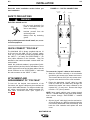
SVM151-A
July, 2000
TM
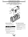
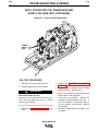
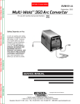
Multi-Weld 350 Arc Converter
For use with machines having Code Numbers: 10645
10736
Safety Depends on You
Lincoln arc welding and cutting
equipment is designed and built
with safety in mind. However,
your overall safety can be increased by proper installation . . .
and thoughtful operation on
your part. DO NOT INSTALL,
OPERATE OR REPAIR THIS
EQUIPMENT WITHOUT
READING THIS MANUAL AND
THE SAFETY PRECAUTIONS
CONTAINED THROUGHOUT.
And, most importantly, think
before you act and be careful.
SERVICE MANUAL
Copyright © 2000 Lincoln Global Inc.
• World's Leader in Welding and Cutting Products •
• Sales and Service through Subsidiaries and Distributors Worldwide •
Cleveland, Ohio 44117-1199 U.S.A. TEL: 216.481.8100 FAX: 216.486.1751 WEB SITE: www.lincolnelectric.com
i
i
SAFETY
WARNING
CALIFORNIA PROPOSITION 65 WARNINGS
Diesel engine exhaust and some of its constituents
are known to the State of California to cause cancer, birth defects, and other reproductive harm.
The Above For Diesel Engines
The engine exhaust from this product contains
chemicals known to the State of California to cause
cancer, birth defects, or other reproductive harm.
The Above For Gasoline Engines
ARC WELDING can be hazardous. PROTECT YOURSELF AND OTHERS FROM POSSIBLE SERIOUS INJURY OR DEATH.
KEEP CHILDREN AWAY. PACEMAKER WEARERS SHOULD CONSULT WITH THEIR DOCTOR BEFORE OPERATING.
Read and understand the following safety highlights. For additional safety information, it is strongly recommended that you
purchase a copy of “Safety in Welding & Cutting - ANSI Standard Z49.1” from the American Welding Society, P.O. Box 351040,
Miami, Florida 33135 or CSA Standard W117.2-1974. A Free copy of “Arc Welding Safety” booklet E205 is available from the
Lincoln Electric Company, 22801 St. Clair Avenue, Cleveland, Ohio 44117-1199.
BE SURE THAT ALL INSTALLATION, OPERATION, MAINTENANCE AND REPAIR PROCEDURES ARE
PERFORMED ONLY BY QUALIFIED INDIVIDUALS.
FOR ENGINE
powered equipment.
1.h. To avoid scalding, do not remove the
radiator pressure cap when the engine is
hot.
1.a. Turn the engine off before troubleshooting and maintenance
work unless the maintenance work requires it to be running.
____________________________________________________
1.b.Operate engines in open, well-ventilated
areas or vent the engine exhaust fumes
outdoors.
____________________________________________________
1.c. Do not add the fuel near an open flame welding arc or when the engine is running. Stop
the engine and allow it to cool before refueling to prevent spilled fuel from vaporizing on
contact with hot engine parts and igniting. Do
not spill fuel when filling tank. If fuel is spilled,
wipe it up and do not start engine until fumes
have been eliminated.
____________________________________________________
1.d. Keep all equipment safety guards, covers
and devices in position and in good
repair.Keep hands, hair, clothing and tools
away from V-belts, gears, fans and all other
moving parts when starting, operating or
repairing equipment.
____________________________________________________
1.e. In some cases it may be necessary to remove safety
guards to perform required maintenance. Remove
guards only when necessary and replace them when the
maintenance requiring their removal is complete.
Always use the greatest care when working near moving
parts.
___________________________________________________
1.f. Do not put your hands near the engine fan. Do not attempt to
override the governor or idler by pushing on the throttle control rods while the engine is running.
___________________________________________________
1.g. To prevent accidentally starting gasoline engines while
turning the engine or welding generator during maintenance
work, disconnect the spark plug wires, distributor cap or
magneto wire as appropriate.
ELECTRIC AND
MAGNETIC FIELDS
may be dangerous
2.a. Electric current flowing through any conductor causes
localized Electric and Magnetic Fields (EMF). Welding
current creates EMF fields around welding cables and
welding machines
2.b. EMF fields may interfere with some pacemakers, and
welders having a pacemaker should consult their physician
before welding.
2.c. Exposure to EMF fields in welding may have other health
effects which are now not known.
2.d. All welders should use the following procedures in order to
minimize exposure to EMF fields from the welding circuit:
2.d.1. Route the electrode and work cables together - Secure
them with tape when possible.
2.d.2. Never coil the electrode lead around your body.
2.d.3. Do not place your body between the electrode and
work cables. If the electrode cable is on your right
side, the work cable should also be on your right side.
2.d.4. Connect the work cable to the workpiece as close as
possible to the area being welded.
2.d.5. Do not work next to welding power source.
Mar ‘95
ii
ii
SAFETY
ELECTRIC SHOCK can kill.
ARC RAYS can burn.
3.a. The electrode and work (or ground) circuits
are electrically “hot” when the welder is on.
Do not touch these “hot” parts with your bare
skin or wet clothing. Wear dry, hole-free
gloves to insulate hands.
4.a. Use a shield with the proper filter and cover
plates to protect your eyes from sparks and
the rays of the arc when welding or observing
open arc welding. Headshield and filter lens
should conform to ANSI Z87. I standards.
3.b. Insulate yourself from work and ground using dry insulation.
Make certain the insulation is large enough to cover your full
area of physical contact with work and ground.
4.b. Use suitable clothing made from durable flame-resistant
material to protect your skin and that of your helpers from
the arc rays.
In addition to the normal safety precautions, if welding
must be performed under electrically hazardous
conditions (in damp locations or while wearing wet
clothing; on metal structures such as floors, gratings or
scaffolds; when in cramped positions such as sitting,
kneeling or lying, if there is a high risk of unavoidable or
accidental contact with the workpiece or ground) use
the following equipment:
• Semiautomatic DC Constant Voltage (Wire) Welder.
• DC Manual (Stick) Welder.
• AC Welder with Reduced Voltage Control.
4.c. Protect other nearby personnel with suitable, non-flammable
screening and/or warn them not to watch the arc nor expose
themselves to the arc rays or to hot spatter or metal.
3.c. In semiautomatic or automatic wire welding, the electrode,
electrode reel, welding head, nozzle or semiautomatic
welding gun are also electrically “hot”.
3.d. Always be sure the work cable makes a good electrical
connection with the metal being welded. The connection
should be as close as possible to the area being welded.
3.e. Ground the work or metal to be welded to a good electrical
(earth) ground.
3.f. Maintain the electrode holder, work clamp, welding cable and
welding machine in good, safe operating condition. Replace
damaged insulation.
3.g. Never dip the electrode in water for cooling.
3.h. Never simultaneously touch electrically “hot” parts of
electrode holders connected to two welders because voltage
between the two can be the total of the open circuit voltage
of both welders.
3.i. When working above floor level, use a safety belt to protect
yourself from a fall should you get a shock.
3.j. Also see Items 6.c. and 8.
FUMES AND GASES
can be dangerous.
5.a. Welding may produce fumes and gases
hazardous to health. Avoid breathing these
fumes and gases.When welding, keep
your head out of the fume. Use enough
ventilation and/or exhaust at the arc to keep
fumes and gases away from the breathing zone. When
welding with electrodes which require special
ventilation such as stainless or hard facing (see
instructions on container or MSDS) or on lead or
cadmium plated steel and other metals or coatings
which produce highly toxic fumes, keep exposure as
low as possible and below Threshold Limit Values (TLV)
using local exhaust or mechanical ventilation. In
confined spaces or in some circumstances, outdoors, a
respirator may be required. Additional precautions are
also required when welding on galvanized steel.
5.b. Do not weld in locations near chlorinated hydrocarbon vapors
coming from degreasing, cleaning or spraying operations.
The heat and rays of the arc can react with solvent vapors to
form phosgene, a highly toxic gas, and other irritating
products.
5.c. Shielding gases used for arc welding can displace air and
cause injury or death. Always use enough ventilation,
especially in confined areas, to insure breathing air is safe.
5.d. Read and understand the manufacturer’s instructions for this
equipment and the consumables to be used, including the
material safety data sheet (MSDS) and follow your
employer’s safety practices. MSDS forms are available from
your welding distributor or from the manufacturer.
5.e. Also see item 1.b.
Mar ‘95
iii
iii
SAFETY
WELDING SPARKS can
cause fire or explosion.
6.a. Remove fire hazards from the welding area.
If this is not possible, cover them to prevent
the welding sparks from starting a fire.
Remember that welding sparks and hot
materials from welding can easily go through small cracks
and openings to adjacent areas. Avoid welding near
hydraulic lines. Have a fire extinguisher readily available.
6.b. Where compressed gases are to be used at the job site,
special precautions should be used to prevent hazardous
situations. Refer to “Safety in Welding and Cutting” (ANSI
Standard Z49.1) and the operating information for the
equipment being used.
6.c. When not welding, make certain no part of the electrode
circuit is touching the work or ground. Accidental contact can
cause overheating and create a fire hazard.
6.d. Do not heat, cut or weld tanks, drums or containers until the
proper steps have been taken to insure that such procedures
will not cause flammable or toxic vapors from substances
inside. They can cause an explosion even though they have
been “cleaned”. For information, purchase “Recommended
Safe Practices for the Preparation for Welding and Cutting of
Containers and Piping That Have Held Hazardous
Substances”, AWS F4.1 from the American Welding Society
(see address above).
6.e. Vent hollow castings or containers before heating, cutting or
welding. They may explode.
6.f. Sparks and spatter are thrown from the welding arc. Wear oil
free protective garments such as leather gloves, heavy shirt,
cuffless trousers, high shoes and a cap over your hair. Wear
ear plugs when welding out of position or in confined places.
Always wear safety glasses with side shields when in a
welding area.
6.g. Connect the work cable to the work as close to the welding
area as practical. Work cables connected to the building
framework or other locations away from the welding area
increase the possibility of the welding current passing
through lifting chains, crane cables or other alternate circuits.
This can create fire hazards or overheat lifting chains or
cables until they fail.
6.h. Also see item 1.c.
CYLINDER may explode
if damaged.
7.a. Use only compressed gas cylinders
containing the correct shielding gas for the
process used and properly operating
regulators designed for the gas and
pressure used. All hoses, fittings, etc. should be suitable for
the application and maintained in good condition.
7.b. Always keep cylinders in an upright position securely
chained to an undercarriage or fixed support.
7.c. Cylinders should be located:
• Away from areas where they may be struck or subjected to
physical damage.
• A safe distance from arc welding or cutting operations and
any other source of heat, sparks, or flame.
7.d. Never allow the electrode, electrode holder or any other
electrically “hot” parts to touch a cylinder.
7.e. Keep your head and face away from the cylinder valve outlet
when opening the cylinder valve.
7.f. Valve protection caps should always be in place and hand
tight except when the cylinder is in use or connected for
use.
7.g. Read and follow the instructions on compressed gas
cylinders, associated equipment, and CGA publication P-l,
“Precautions for Safe Handling of Compressed Gases in
Cylinders,” available from the Compressed Gas Association
1235 Jefferson Davis Highway, Arlington, VA 22202.
FOR ELECTRICALLY
powered equipment.
8.a. Turn off input power using the disconnect
switch at the fuse box before working on
the equipment.
8.b. Install equipment in accordance with the U.S. National
Electrical Code, all local codes and the manufacturer’s
recommendations.
8.c. Ground the equipment in accordance with the U.S. National
Electrical Code and the manufacturer’s recommendations.
Mar ‘95
iv
iv
SAFETY
PRÉCAUTIONS DE SÛRETÉ
Pour votre propre protection lire et observer toutes les instructions
et les précautions de sûreté specifiques qui parraissent dans ce
manuel aussi bien que les précautions de sûreté générales suivantes:
Sûreté Pour Soudage A L’Arc
1. Protegez-vous contre la secousse électrique:
a. Les circuits à l’électrode et à la piéce sont sous tension
quand la machine à souder est en marche. Eviter toujours
tout contact entre les parties sous tension et la peau nue
ou les vétements mouillés. Porter des gants secs et sans
trous pour isoler les mains.
b. Faire trés attention de bien s’isoler de la masse quand on
soude dans des endroits humides, ou sur un plancher
metallique ou des grilles metalliques, principalement dans
les positions assis ou couché pour lesquelles une
grande partie du corps peut être en contact avec la
masse.
c. Maintenir le porte-électrode, la pince de masse, le câble
de soudage et la machine à souder en bon et sûr état
defonctionnement.
d. Ne jamais plonger le porte-électrode dans l’eau pour le
refroidir.
e. Ne jamais toucher simultanément les parties sous tension
des porte-électrodes connectés à deux machines à souder parce que la tension entre les deux pinces peut être le
total de la tension à vide des deux machines.
f. Si on utilise la machine à souder comme une source de
courant pour soudage semi-automatique, ces precautions
pour le porte-électrode s’applicuent aussi au pistolet de
soudage.
2. Dans le cas de travail au dessus du niveau du sol, se protéger contre les chutes dans le cas ou on recoit un choc. Ne
jamais enrouler le câble-électrode autour de n’importe quelle
partie du corps.
3. Un coup d’arc peut être plus sévère qu’un coup de soliel,
donc:
a. Utiliser un bon masque avec un verre filtrant approprié
ainsi qu’un verre blanc afin de se protéger les yeux du
rayonnement de l’arc et des projections quand on soude
ou quand on regarde l’arc.
b. Porter des vêtements convenables afin de protéger la
peau de soudeur et des aides contre le rayonnement de
l‘arc.
c. Protéger l’autre personnel travaillant à proximité au
soudage à l’aide d’écrans appropriés et non-inflammables.
4. Des gouttes de laitier en fusion sont émises de l’arc de
soudage. Se protéger avec des vêtements de protection
libres de l’huile, tels que les gants en cuir, chemise épaisse,
pantalons sans revers, et chaussures montantes.
5. Toujours porter des lunettes de sécurité dans la zone de
soudage. Utiliser des lunettes avec écrans lateraux dans les
zones où l’on pique le laitier.
6. Eloigner les matériaux inflammables ou les recouvrir afin de
prévenir tout risque d’incendie dû aux étincelles.
7. Quand on ne soude pas, poser la pince à une endroit isolé
de la masse. Un court-circuit accidental peut provoquer un
échauffement et un risque d’incendie.
8. S’assurer que la masse est connectée le plus prés possible
de la zone de travail qu’il est pratique de le faire. Si on place
la masse sur la charpente de la construction ou d’autres
endroits éloignés de la zone de travail, on augmente le risque
de voir passer le courant de soudage par les chaines de levage, câbles de grue, ou autres circuits. Cela peut provoquer
des risques d’incendie ou d’echauffement des chaines et des
câbles jusqu’à ce qu’ils se rompent.
9. Assurer une ventilation suffisante dans la zone de soudage.
Ceci est particuliérement important pour le soudage de tôles
galvanisées plombées, ou cadmiées ou tout autre métal qui
produit des fumeés toxiques.
10. Ne pas souder en présence de vapeurs de chlore provenant
d’opérations de dégraissage, nettoyage ou pistolage. La
chaleur ou les rayons de l’arc peuvent réagir avec les
vapeurs du solvant pour produire du phosgéne (gas fortement toxique) ou autres produits irritants.
11. Pour obtenir de plus amples renseignements sur la sûreté,
voir le code “Code for safety in welding and cutting” CSA
Standard W 117.2-1974.
PRÉCAUTIONS DE SÛRETÉ POUR
LES MACHINES À SOUDER À
TRANSFORMATEUR ET À
REDRESSEUR
1. Relier à la terre le chassis du poste conformement au code
de l’électricité et aux recommendations du fabricant. Le dispositif de montage ou la piece à souder doit être branché à
une bonne mise à la terre.
2. Autant que possible, I’installation et l’entretien du poste
seront effectués par un électricien qualifié.
3. Avant de faires des travaux à l’interieur de poste, la
debrancher à l’interrupteur à la boite de fusibles.
4. Garder tous les couvercles et dispositifs de sûreté à leur
place.
Mar. ‘93
v
- MASTER TABLE OF CONTENTS FOR ALL SECTIONS -
Page
Safety .................................................................................................................................................i-iv
Installation.............................................................................................................................Section A
Operation...............................................................................................................................Section B
Accessories ..........................................................................................................................Section C
Maintenance ..........................................................................................................................Section D
Theory of Operation .............................................................................................................Section E
Troubleshooting and Repair ................................................................................................Section F
Electrical Diagrams ..............................................................................................................Section G
Parts Manual......................................................................................................................P361 Series
MULTI-WELD 350
v
Section A-1
TABLE OF CONTENTS
- INSTALLATION SECTION -
Section A-1
Installation.............................................................................................................................Section A
Technical Specifications ..............................................................................................................A-2
Safety Precautions ......................................................................................................................A-3
Quick-Connect “Pig-Tails” ...........................................................................................................A-3
Attachment and Arrangement of “Pig-Tails” ................................................................................A-3
Work Connection.........................................................................................................................A-4
Case Grounding ..........................................................................................................................A-4
Inter-Connection of Converters ...................................................................................................A-4
Power Source Setup ...................................................................................................................A-6
MULTI-WELD 350
A-2
A-2
INSTALLATION
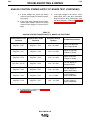
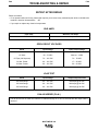
TECHNICAL SPECIFICATIONS - MULTI-WELD 350 (K1735-1)
ELECTRICAL SPECIFICATIONS
Amps (DC+)
Volts (DC+)
Output Rating @ 50°C (122°F)
350
34
Input Rating @ 50°C (122°F)
165
80
Max. Input Range
50-113 (Peak)
Max. O.C.V.
78
Output Preset Range
30-350
15-40
PHYSICAL DIMENSIONS
Height
Width
Depth
Net Weight
11.6 in.
10.0 in.
21.5 in.
59.5 lbs.
295 mm
254 mm
546 mm
27.0 kg.
TEMPERATURE RANGES
Operating Temperature Range
Storage Temperature Range
-40 to +122°F
-40 to +185°F
-20 to +50°C
-40 to +85°C
MULTI-WELD 350
A-3
A-3
INSTALLATION
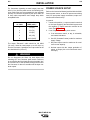
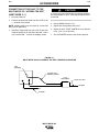
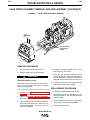
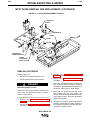
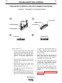
Read this entire installation section before you
start installation.
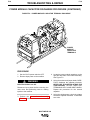
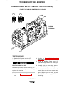
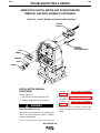
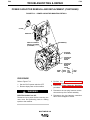
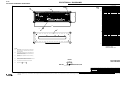
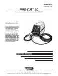
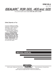
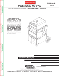
FIGURE A.1 – PIG-TAIL CONNECTIONS
TO POWER
TO
SOURCE
WORK
TO ELECT.
SAFETY PRECAUTIONS
WARNING
ELECTRIC SHOCK can kill.
• Do not touch electrically live
parts or electrodes with your
skin or wet clothing.
IN
ELECT.
+
+
INPUT
ELECTRODE
+
+
• Insulate yourself from the
work and ground.
• Always wear dry insulating
gloves.
Only qualified personnel should install, use, or service this equipment.
BOTTOM VIEW
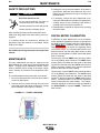
QUICK-CONNECT “PIG-TAILS”
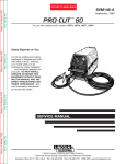
The Multi-Weld 350 is factory provided with two 21
in.(53 cm) long 2/0 AWG (70 mm2) “pig-tail” cables.
Their 0.5" (13 mm) hole lug ends are routed through
the “INPUT +” (on back) and “ELECTRODE +” (on
front) cable channels of the Converter. They are
attached to the bottom-accessed covered cable connection studs.
Attach the preferred standard, user-provided Quickconnect terminal (such as Lincoln Twist-Mate or Tweco
2-MPC type) to the cut-off end of these cables. Use the
female connector on the “ELECTRODE +” cable and
the male connector on the “INPUT +” cable.
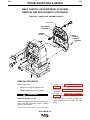
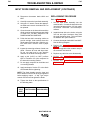
ATTACHMENT AND
ARRANGEMENT OF “PIG-TAILS”
To best suit the desired inter-connection of the
Converters, the “pig-tail” cables may be routed into the
front or back cable channels. For single or double “pigtail” cables, route through the bottom-accessed covered cable connection studs. (See Figures A.1
and B.1.)
ELECT.
IN
+
+
TO POWER
TO ELECT.
SOURCE
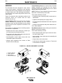
To connect the “pig-tail” cables to the Converter:
1. Stand the Converter vertically on its rear handle
and skid to gain access to the bottom stud covers.
Then remove the two 0.25"(6.3 mm) screws securing each cover and fold out the cover insulation.
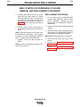
2. Route the appropriate “pig-tail” cable lug ends
under the skid rail (for strain-relief) through the
desired front and/or rear corner channels to the
exposed 0.5" (13 mm) stud. Remove the flange
nut with a .75" (19 mm) wrench.
NOTE: Input supply cable(s) must connect through
“INPUT +” labeled channels, and output weld cable(s)
must connect through “ELECTRODE +” labeled
channels.
3. Slip the “pig-tail” cable lug(s) over the stud and resecure the flange nut. Make sure that the lug(s) do
not touch any sheetmetal of the stud housing. Fold
back the cover insulation and replace the stud
cover.
MULTI-WELD 350
A-4
A-4
INSTALLATION
WARNING
Be sure to follow the safety practice to
use the female connector on the cable
which would normally be electrically "hot"
(supply lead) if disconnected when the
system is energized, and the male on the
normally “cold” (load lead) side. If practical, shut off
power before connecting or disconnecting terminals.
WORK CONNECTION
Each Converter in the Multi-Weld system must have its
individual “Work” lead connected (clipped) to the work.
The #3 AWG (27 mm2) Work clip lead must have clean
metal connection to the work to complete the DC input
supply and output power circuits of the Multi-Weld 350.
WARNING
Do not disconnect the Work clip lead without first
switching OFF the Converter panel switch. Failure to
do so will allow the Work lead clip to be electrically “hot”
to work and “hot” to the electrode, through the circuit of
the Converter, for about 5 seconds until the input contactor opens.
CASE GROUNDING
As shipped, the case of the Multi-Weld 350 is isolated
from all of the DC input and output welding terminals.
It is equipped with a grounding terminal screw
(.31” / 7.9 mm) marked with the symbol
located on
the bottom rear of the base assembly. (Refer to the bottom view figure.) In order to comply with CSA and UL
case grounding specifications, this terminal is provided
for connection to weldment work that must be properly
grounded per methods meeting local and national electrical codes. Refer to “Safety in Welding, Cutting and
Allied Processes,” ANSI Z49.1 (US) and W117.2
(Canada).
Connect the Multi-Weld grounding lead to the work
piece separately from the Work clip. If the same clip is
used for both ground and work connection, the MultiWeld case will be electrically “hot” to the work if the clip
is removed without first switching OFF the panel
switch. ( Refer to the Work clip WARNING).
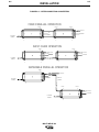
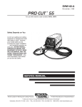
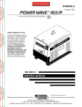
INTER-CONNECTION OF
CONVERTERS
The input and electrode cables of the Multi-Weld 350
Converters may be inter-connected in a Multi-Weld
system using any combination of Distribution Box(es)
(see Figure B.1), paralleling (CC mode only) and
“daisy-chaining” (see Figure A.2). Choose the configuration that best fits the field application setup within
the capacity of the power source supplying the system.
Power Source (Volts x Amp) capacity > 1.1 x
Sum of Converters’ (Volts x Amps) arcs
WARNING
Paralelled units may be powered from more than one
source. Disconnect all inputs, including outputs from
other sources, before working on the equipment.
Before removing the parallel jumper, be sure both
Converters are switched OFF. If not, the male side of
the first disconnection will be electrically “hot” to work.
Since any case fault would only involve the DC welding
circuit, the size of the grounding lead should have the
capacity to ground the potential fault current without
burning open. Use at least #6 AWG (13 mm2), but need
not exceed the size of the input cable supplying the
Multi-Weld 350.
MULTI-WELD 350
A-5
A-5
INSTALLATION
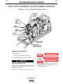
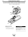
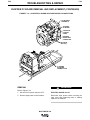
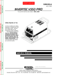
FIGURE A.2 – INTER-CONNECTING CONVERTERS
FIXED PARALLEL OPERATION
ELECT.
ELECT.
ELECT.
+
+
+
TO ELECT.
TO
TO WORK
WORK
TO POWER
SOURCE
IN
IN
IN
IN
+
+
+
+
DAISY CHAIN OPERATION
ELECT.
ELECT.
+
+
TO ELECT.
TO ELECT.
TO WORK
TO WORK
TO POWER
SOURCE
IN
+
IN
IN
+
+
SEPARABLE PARALLEL OPERATION
ELECT.
+
TO ELECT.
TO WORK
TO POWER
PARALLEL
JUMPER
SOURCE
IN
+
ELECT.
+
ELECT.
+
TO ELECT.
TO WORK
TO POWER
SOURCE
IN
+
MULTI-WELD 350
A-6
INSTALLATION
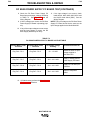
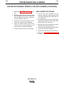
For Converters (operating at rated output) less than
200 ft. (61 m) from the power source, the following minimum cable sizes are recommended for the indicated
quantity of Converters supplied by the input cable run
to keep cable temperature and voltage drop within
acceptable limits:
A-6
POWER SOURCE SETUP
Refer to the Instruction Manual provided with the MultiSource power source, or other DC power source being
used, for input power supply connections, output connections and controls setup.
In general:
Converters
on Cable
Cable Size
AWG (mm2 )
1
1/0 (50)
1. Connect the positive (+) output connection terminal
to the input supplying the Multi-Weld system and
the negative (-) output connection terminal to the
work. (See Figure A.1.)
2
2/0 (70)
2. If not using a Multi-Source power source:
3
3/0 (95)
4
4/0 (120)
5
2x3/0 (2x95)
a. If an inductance control, or tap, is selectable,
use lowest inductance.
b. Use CC (Constant Current) mode for maximum
supply voltage.
The output “Electrode” cable should be 2/0 AWG
(70 mm2) if sized for rated output up to 200 ft.(61 m)
from the Converter. If paralleled, the output cable to the
arc should be 4/0 (120 mm2).
c. Set panel output control to maximum for maximum current capacity.
d. Activate output with the “output terminals on”
switch, or jumper (2-4 on Lincoln Electric terminal strips).
WARNING
Do not disconnect the Work clip lead without first
switching OFF the Converter panel switch. Failure to
do so will allow the Work lead clip to be electrically “hot”
to work and “hot” to the electrode, through the circuit of
the Converter, for about 5 seconds until the input contactor opens.
MULTI-WELD 350
Section B-1
TABLE OF CONTENTS
- OPERATION SECTION -
Section B-1
Operation...............................................................................................................................Section B
Safety Instructions.......................................................................................................................B-2
Product Description.....................................................................................................................B-3
Recommended Equipment and Processes.................................................................................B-4
Multi-System Power Source .................................................................................................B-4
Distribution Box.....................................................................................................................B-4
“Pig-Tail” Leads and Connectors ..........................................................................................B-4
Remote Output Control Options ...........................................................................................B-5
CV Mode Wire Welding ........................................................................................................B-5
CC Mode Stick Welding and Gouging..................................................................................B-5
Front Panel Controls ...................................................................................................................B-6
Recessed Panel Controls............................................................................................................B-7
Paralleled Converters..................................................................................................................B-8
Remote Control of Paralleled Converters ...................................................................................B-8
Transporting and Storage of the Multi-Weld 350 ........................................................................B-8
Cable Handling .....................................................................................................................B-8
Transporting..........................................................................................................................B-9
Storage .................................................................................................................................B-9
Protection Features.....................................................................................................................B-9
Fan as Needed (F.A.N.)........................................................................................................B-9
Over-Voltage Protection........................................................................................................B-9
Over-Current Protection........................................................................................................B-9
Over-Temperature Shutdown................................................................................................B-9
MULTI-WELD 350
B-2
OPERATION
OPERATING INSTRUCTIONS
Read and understand this entire section of operating
instructions before operating the machine.
SAFETY INSTRUCTIONS
WARNING
ELECTRIC SHOCK can kill.
• Do not touch electrically live parts or
electrodes with your skin or wet clothing.
• Insulate yourself from the work and
ground.
• Always wear dry insulating gloves.
FUMES AND GASES CAN BE
DANGEROUS.
• Keep your head out of fumes.
• Use ventilation or exhaust to remove
fumes from breathing zone.
WELDING SPARKS CAN CAUSE
FIRE OR EXPLOSION.
• Keep flammable material away.
• Do not weld on containers that have held
combustibles.
ARC RAYS CAN BURN.
• Wear eye, ear, and body protection.
Observe additional Safety Guidelines detailed in
the beginning of this manual.
MULTI-WELD 350
B-2
B-3
OPERATION
B-3
PRODUCT DESCRIPTION
The Multi-Weld 350 Arc Converter (K1735-1) is part of
a Multi-Weld system, ideally suited for construction site
welding. It uses a single DC power source as the
only input supply and provides independent, full-range
control of up to 350A continuous with each Converter
arc for + polarity stick and wire processes, as well as
for arc-air gouging. (See Figure B.1.)
FIGURE B.1 – MULTI-WELD SYSTEM
The Multi-Weld 350 is a DC to DC Converter that converts higher voltage/lower current input power to lower
voltage/higher current output power with over 90% efficiency.
• Constant Voltage (CV) mode for positive polarity
cored and solid wire welding with arc-powered feeders (such as the LN-25).
For example, a single 600A continuous rated 70-80V
power source could supply up to five Multi-Weld 350
converters, each wire welding at 300 amps, or about
ten converters for stick welding at 150 amps with 2629V at the arcs.
Portable
The Multi-Weld 350 Arc Converter is a single “world”
model built to IEC and CSA standards and meeting the
specific needs inherent to construction site welding:
• The Converter is powered by the welding cable from
the DC power source, without the safety hazard of
high AC input supply voltages.
Versatile
• Constant Current (CC) mode for stick and gouging.
Includes Hot Start and Arc Force controls to optimize
CC performance, and can be paralleled for higher
capacity welding and arc gouging.
• The Multi-Weld 350 can be moved quickly. The lightweight Converter is easy to carry or pull and is small
enough to fit through a 15" (38 cm) diameter or 12" x
16" (31x 41 cm) elliptical man-hole.
• Welding controls are near the arc without long control cables, and a receptacle is provided for an
optional remote for even closer user output control.
MULTI-WELD 350
B-4
B-4
OPERATION
Simple
• Easy installation with 10 ft. (3 m) work clip lead and
user preference quick-connect “pig-tails” for input
and electrode weld cables.
• Easy setup with only a few intuitive welding controls
and lit displays. This includes a single Power/Mode
switch with Input level light, and a single presettable
Output Control with separate digital meters for Amps
and Volts, featuring post-weld five second memory
display.
• Easy Service with quick-to-replace cable “pig-tails”
and “plug-in” assembly modules, including accessible PC boards and interchangeable “plug-n-play”
panel instruments.
RECOMMENDED EQUIPMENT AND
PROCESSES
MULTI-SYSTEM POWER SOURCE
The Multi-Source 40KW, 80VDC buss power source
(K1752-1) is recommended for use in the Multi-Weld
system. However, other DC power sources capable of
supplying the required system buss current, at above
60 volts, may be used. It is recommended that this
power source have lower output inductance (choke)
such as the Lincoln Electric DC-1000, DC-655 or DC600 set for maximum output in CC mode. The power
source output VA capacity should be 10% greater than
the sum of the maximum VA of the converter arcs,
which may all be simultaneously welding or gouging:
Robust
• Capacity is rated for continuous operation at 350
amps in 50°C (122°F) ambient temperature, and can
be paralleled to multiply CC mode output rating.
• Overload protection is provided with electronic limiting of output current, and with thermostat and overvoltage shutdown protection that automatically reset.
• Outdoor operation protected with sealed control and
power electronics compartments, with sealed interconnections, housing “potted” circuit boards, and
using “Central-Air” cooling with “Fan-As-Needed” for
less dirt intake.
• Handling (and mishandling protection) is enhanced
with light, but durably designed, aluminum construction with front to back, top and bottom, handles (also
serving as “roll bar” and skid), and a sheetmetal shell
attached with 1/4" steel threaded fasteners.
Power Source (Volts x Amps) capacity > 1.1 x
Sum of Converters’ (Volts x Amps) arcs
DISTRIBUTION BOX
The Multi-Weld Distribution Box (K1736-1) is available
for interconnection of the Multi-System using the same
“pig-tail” connection method provided with the MultiWeld 350 converter. Six cable strain-relief ports are
provided for connection of up to (12) cables for distribution or "daisy-chain" inter-connection to other boxes.
Four “pig-tail” leads (see below) are included with the
Box.
“PIG-TAIL” LEADS AND CONNECTORS
Accessory “pig-tail” leads and Twist-Mate connectors
are available from Lincoln for extra connections to the
Multi-Weld 350 or the Distribution Box:
Order No.
Description:
CL012705
22 in.(56 cm) long 2/0 (70 mm2) cable
with 0.5 in.(13 mm) hole lug and cut-off
ends.
K852-70
Twist-Mate male insulated plug for
1/0-2/0 (50-70 mm2) cable.
K852-95
Twist-Mate male insulated plug for
2/0-3/0 (70-95 mm2) cable.
K1759-70
Twist-Mate female insulated receptacle
for 1/0-2/0 (50-70 mm2) cable.
K1759-95
Twist-Mate female insulated receptacle
for 2/0-3/0 (70-95 mm2) cable.
MULTI-WELD 350
B-5
B-5
OPERATION
REMOTE OUTPUT CONTROL OPTIONS
The Multi-Weld 350 is provided with a 6-pin remote
receptacle to permit use with the 25 ft.(7.6 m) K857 or
100 ft. (30.4 m) K857-1 Remote Output Control
options. The remote receptacle can also be used with
the LN-25 equipped with the K444-1 Remote Control
option. These remotes have single-turn resolution on a
Minimum to Maximum numbered dialplate.
CC MODE STICK WELDING
AND GOUGING
The CC mode recommended processes are positive
(+) polarity stick and arc gouging within the output
capacity of single, or paralleled, Converters, including:
Shielded Metal Arc Welding (SMAW)
E6010/6011:
FW5P/180 (3/32-1/4)
“fast-freeze”
E6013:
FW37 (3/32-3/16)
“fill-freeze”
E7010/8010:
SA85/70+ (3/32-7/32)
“fast-freeze” HT pipe
E7018/7028:
JW LH70/3800 (3/32-5/32)
“low-hydrogen”
E7024/6027:
JW1,3/2 (1/8-5/16)
“fast-fill”
CV MODE WIRE WELDING
The Converter in CV mode was designed for use with
an arc-powered wire feeder like the LN-25. The
Converter output is always “hot” when the mode switch
is not OFF. Therefore it is recommended that the LN25 model be equipped with the internal contactor in
order to have a “cold” electrode when the gun trigger is
released.
The CV mode recommended processes are positive
(+) polarity wire welding within the output capacity of
the Converter, including:
Arc Air Carbon (AAC)
Flux Cored Arc Welding (FCAW)
Innershield:
NS3M (5/64-3/32)
NR305 (.068)
Outershield:
OS-70 (1/16-5/64)
OS-71 (.045-1/16)
Gouging:
MC-710 (.045-5/64)
Gas Metal Arc Welding (GMAW)
Carbon Steel: L50/56 (.030-1/16)
MULTI-WELD 350
Carbons (5/32-3/8)
B-6
B-6
OPERATION
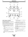
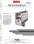
FIGURE B.2 – FRONT PANEL CONTROLS
1
3
4
5
6
2
8
9
10
7
WORK
INPUT
ELECTRODE
+
+
FRONT PANEL CONTROLS
• Only VOLTS digital meter is lit, displaying the
preset voltage setting.
The numbered items of Figure B.2 match the numbered items described below:
• Output will be on at the output voltage setting.
These few instruments and controls are basic to the
operation and monitoring of the Converter. They are
intuitively laid out so that the panel left side is weld current related, and the right side is weld voltage related:
(1) Input Power/ Mode Switch has three positions:
Center is OFF, which shuts off input power to the
Converter.
• Neither displays nor output is on if in OFF
position.
Left is on for CC (constant current) welding mode.
(2) Output Control has 3-3/4 turn resolution with slipclutch to prevent control pot damage.
In CC mode it presets AMPS (30-350A range)
when not welding and adjusts actual arc current
while welding.
In CV mode it presets VOLTS (15-40v range)
when not welding and adjusts actual arc voltage
while welding.
(3) AMPS Digital Meter is a 3-1/2 digit LED meter
which displays:
Preset AMPS in CC mode when not welding.
• Only AMPS digital meter is lit, displaying the
preset current setting.
“Blank” in CV mode when not welding.
• Output will be on at o.c.v. (open circuit voltage).
Actual AMPS while welding in both CC and CV
modes.
Right is on for CV (constant voltage) welding
mode.
MULTI-WELD 350
B-7
OPERATION
B-7
Average AMPS for about 7 seconds after welding
stops in CC and CV modes only.
RECESSED PANEL CONTROLS
• The 5 second memory display is indicated by the
display’s left-most decimal point blinking, and is
interrupted if arc is restarted.
These instruments are recessed behind a screwsecured hinged cover panel, and are not typically
required for normal operator access. They may be left
covered, as factory set, or set up as desired with or
without the hinged cover secured:
Accuracy of Actual AMPS is within 3%, and typically within 10 amps of Preset.
• An Actual AMPS meter calibration adjustment
trimmer is provided. (See the Maintenance section).
Two front screws secure the meter bezel, which
holds a replaceable spatter shield lens (Lincoln
part no. T14807-9).
(4) VOLTS Digital Meter is a 3-1/2 digit LED meter
which displays:
Preset VOLTS in CV mode when not welding.
“Blank” in CC mode when not welding.
Actual VOLTS while welding in both CV and CC
modes.
Average VOLTS for about 7 seconds after welding
stops in CV and CC modes only.
• The 7 second memory display is indicated by the
display’s left-most decimal point blinking, and is
interrupted if arc is restarted.
Accuracy of Actual VOLTS is within 3%, and typically within 1 volt of Preset.
• An Actual VOLTS meter calibration adjustment
trimmer is provided. (See the Maintenance section).
Two front screws secure the meter bezel, which
holds a replaceable spatter shield lens.
(5) Thermal Shutdown (yellow) Light turns on if output is shutdown because internal overheating has
occurred. (See Over Temperature Shutdown in
this section).
(6) Input Voltage (green) Light indicates appropriate
level of input supply voltage:
“On” for adequate input voltage over 50 V for CC or
CV mode.
“Off” for inadequate input voltage under 50 V, no
input or Power Switch OFF.
NOTE: If green light is “blinking,” the input voltage may
be drifting above and below the 50 V level due to loads
on supply and cables. This may also cause the input
contactor to “chatter.”
(7) Hot Start Control is provided to enhance arc
starting in both CC and CV modes with an extra
output “boost” at the arc strike that returns to the
setting level in less than a second (about 0.30
sec. in CC mode, and 0.045 sec. in CV mode).
This extra Hot Start amplitude is adjustable from
“0” (no extra) to “10” (100% of setting extra), with
the factory set “5” (center) position typically good
for most weld starting. However, “0” may provide
smoother starting for fine wire CV MIG.
(8) Arc Force Control is only functional in the CC
mode with Stick/Gouge slope. (See below). Arc
Force prevents “stubbing” of the electrode by providing extra weld current if the arc voltage drops
below about 14 V. This extra weld current is
adjustable from “-10” (no extra) to “+10” (60% of
setting extra), with the factory set “0” (center)
position typically good for most welding.
(9) CC Slope Switch is provided to enhance stick
welding on “fast-freeze” type electrodes (such as
E6010 and E7010) typically used on pipe welding
applications for fast root pass vertical down
"drag" technique (not “whipping”). For this type of
application, improved operating appeal may be
obtained if the CC Slope is switched from the factory set STICK/GOUGE position to the PIPE
position.
NOTE: The PIPE position uses a “drooping” type
slope (~22v/100A), so preset current (not actual
current) accuracy may be affected if arc length
voltage is not maintained at the typical 28 V used
for these electrodes. Typically this error should
not be more than about 10 A.
(10) Remote Control Receptacle is provided to permit the use of an optional Remote output control
to provide operator control even closer to the arc.
Connecting the Remote plug to this receptacle
automatically transfers output control from the
panel Output Control (item (2) above) to the
Remote pot control, which will function the same
but with only single-turn resolution.
MULTI-WELD 350
B-8
OPERATION
Disconnecting the Remote plug from this receptacle automatically transfers output control back to
the panel Output Control (item (2) above).
Remote output On/Off switching can also be done
through this Remote Control receptacle by performing the following wiring changes:
1. Making sure the input to the Converter is
removed, remove the case wraparound.
2. Locate the 4-pin plug (P21) on the back panel
of the control box module, and cut the jumper
lead looping from the back of the plug. (Refer to
the Wiring Diagram in the Electrical Diagrams
section.) Insulate the cut lead ends and leave
long enough to possibly splice back together
again at some future time.
3. Replace the case wraparound.
4. Connect a user-provided remote switch between pins D and E of an MS3106A-18-12P
plug (Lincoln part no. S12020-27 with S120241 cable clamp). See the diagram below:
B-8
PARALLELED CONVERTERS
Multi-Weld 350 converters that are paralleled (see INTERCONNECTION OF CONVERTERS in the Installation
section) must each be set up in the same manner in order
to manage the arc current drawn from each:
1. Set to CC mode with CC SLOPE switch set to
STICK/GOUGE.
2. Preset Output Controls of both paralleled
Converters to ~1/2 desired total AMPS.
If arc current from each Converter gets too out of balance (primarily a problem if trying to use CV mode) the
hotter running Converter could go into current-limiting
and/or Thermal shutdown (See OVER-TEMPERATURE SHUTDOWN in the Installation section.) This
might then overload the other, or at least interrupt the
operator’s process. However, no damage will occur to
the Converters.
REMOTE CONTROL OF
PARALLELED CONVERTERS
(FOR CC STICK/GOUGE MODE ONLY)
F
A
B
C
Full Range remote control can be accomplished with a
separate optional Remote output control (see the
Installation section) connected to each Converter. The
current contribution of each Converter will depend on
its remote output setting.
E
Partial Range remote control can be accomplished with
a single Remote Control connected to the output
Converter. The input Converter must be preset with its
panel Output Control to below the minimum desired
output range. The Remote Control, connected to the
output Converter, will control its output to add to the
preset level.
D
Pin:
Remote Function:
A
B
C
D
E
F
Max. of 10K pot
Wiper of 10K pot
Min. of 10K pot
Output Switch
Output Switch
No connection
Remote Output On/Off switching may be set up for
each of the paralleled Converters. Electrically isolated
switches must be used to activate each separately but
simultaneously.
TRANSPORTING AND STORAGE
OF THE MULTI-WELD 350
5. Connect this switch plug to the Multi-Weld 350
Remote Control Receptacle (10) with switch
opened. Closing the switch activates the
Converter output.
CABLE HANDLING
The input and electrode cables are easily disconnected from the quick-connect “pig-tails.” The Work lead
can be reeled around the Multi-Weld 350 case cradled
by the base skid handles, to which the clip can be
secured.
MULTI-WELD 350
B-9
B-9
OPERATION
TRANSPORTING
OVER-CURRENT PROTECTION
The Converter may be carried by one or two persons
using the front and rear top and bottom handles. It can
also be set vertically on a two wheel cart, or horizontally on a wagon, to move it longer distances.
The maximum output current of the Multi-Weld 350 is
electronically limited, to protect internal power components, so as not to exceed about 375 amps average
and 500 amps peak. When the current load starts to
exceed these limits, the output is reduced (lower voltage) to sustain these maximum levels until the current
is reduced, even to a shorted output.
STORAGE
The Multi-Weld 350 may be set on a floor, or shelf, horizontally on its skid, or vertically standing on its rear top
and bottom handles.
PROTECTION FEATURES
The Multi-Weld 350 design features electronic protection systems to help assure reliable operation even
under adverse conditions. These systems include:
FAN AS NEEDED (F.A.N.)
The cooling fan will turn on when the arc starts and
remain on for about a minute after the arc is out to cool
down the power components.
This feature electronically controls the fan so it does
not run continuously when the power switch is turned
on. This will minimize the amount of contaminate and
clogging debris which may be drawn into the
Converter. It enhances the “Central-Air” system design
which intakes lower velocity air through the higher side
louvers and blows it out through the lower back louvers
with higher velocity.
OVER-VOLTAGE PROTECTION
The Multi-Weld 350 input contactor will open if the input
supply voltage is above 113 VDC, and will automatically reclose if the voltage drops back below. During OverVoltage Shutdown the panel displays will be as appropriate for the non-welding mode. (See FRONT PANEL
CONTROLS in this section.)
CAUTION
When the contactor recloses, the output of the
Converter will reactivate. Switching OFF input power
prevents unexpected reactivation.
This feature protects internal components of the
Converter from excessive voltage levels.
Prolonged output at this maximum current limit level
may eventually overheat the Converter’s internal
power components, causing over-temperature shutdown. (See following section.)
Short circuit protection is also provided to reduce maximum output current to about 200 amps, if the output
voltage is reduced, by loading or current limiting, to
below 14 volts for over 7 seconds (indicating a shorted
output). The output current must be interrupted to reset
this reduced protective level.
This maximum 200 amp short circuit level will allow
using the Multi-Weld 350 for “pipe-thawing” applications without causing over-temperature shutdown.
(See following section.)
OVER-TEMPERATURE SHUTDOWN
A second over-load protection switch in the Imbalance
Protector Module was added to Multi-Weld 350 models
with codes 10736 and higher. This module senses for
an imbalance of current between the paralleled
Chopper boards by sensing the differential choke voltage. If this voltage exceeds 1 V for a sustained time,
the Imbalance Protector will also activate over-temperature shutdown to protect the higher current Chopper
board from over heating.
CAUTION
When the thermostat resets, the output of the
Converter will reactivate. Switching OFF input power
prevents reactivation but also shuts off the cooling fan,
which prolongs the reset time.
During Over-Temperature Shutdown the panel displays
will be as appropriate for the non-welding mode. (See
FRONT PANEL CONTROLS in this section.) The fan
will remain running and the Thermal Shutdown (yellow)
Light will be lit until reset. Typically, if shutdown occurs
repeatedly below 300 amps output with fan running,
imbalance of the Chopper board current may likely be
the cause.
MULTI-WELD 350
B-10
NOTES
MULTI-WELD 350
B-10
Section C-1
TABLE OF CONTENTS
- ACCESSORIES SECTION -
Section C-1
Accessories ..........................................................................................................................Section C
Options/Accessories ...................................................................................................................C-2
Field Installed Options .........................................................................................................C-2
Semiautomatic Welding Accessories ..........................................................................................C-2
Connection of Lincoln Electric Wire Feeders..............................................................................C-2
Connection of the LN-25 ......................................................................................................C-3
MULTI-WELD 350
C-2
C-2
ACCESSORIES
OPTIONS/ACCESSORIES
The following options/accessories are available for
your Multi-Weld 350 from your local Lincoln Distributor.
FIELD INSTALLED OPTIONS
K1736-1 DISTRIBUTION BOX - Makes connecting up
to 10 Multi-Weld 350s quick and easy. Contains copper bus bar for connecting multiple “pig-tails.” Four
“pig-tails” included.
K857 25 ft. (7.5 m) or K857-1 100 ft. (30.4 m)
REMOTE CONTROL - Provides 25 ft. or 100 ft. (7.5 m
or 30 m) of remote output control. Connects to 6-pin
receptacle on front of Multi-Weld 350.
SEMIAUTOMATIC WELDING
ACCESSORIES
K449 LN-25 WIRE FEEDER - The LN-25 is perfect for
use with the Multi-Weld 350. It is designed to run
“across-the-arc” with no control cables. This portable
wire feeder offers constant wire feed speed in a rugged
case.
CONNECTION OF LINCOLN
ELECTRIC WIRE FEEDERS
WARNING
WELDING CABLE CONNECTORS
ELECTRIC SHOCK can kill.
Twist-Mate™ plug for fast connection of additional
Multi-Weld 350s.
• Only qualified personnel should perform this maintenance.
K852-70 - Twist-Mate male plug for 1/0-2/0 (50070 mm2) cable.
• Turn the input power OFF at the disconnect switch or fuse box before
working on this equipment.
K852-90 - Twist-Mate male plug for 2/0-3/0 (7095 mm2) cable.
K1759-70 - Twist-Mate female plug for 1/0-2/0 (5070 mm2) cable.
K1759-90 - Twist-Mate female plug for 2/0-3/0 (7095 mm2) cable.
MULTI-WELD 350
• Do not touch electrically hot parts.
C-3
C-3
ACCESSORIES
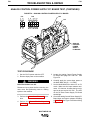
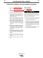
CONNECTION OF THE LN-25 TO THE
MULTI-WELD 350 “ACROSS THE ARC”
(SEE FIGURE C.1.)
CAUTION
If you are using an LN-25 without an internal contactor,
the electrode will be “HOT” when the Multi-Weld 350 is
turned ON.
1. Shut the welder off.
2. Connect the electrode cable from the LN-25 to the
“+” terminal of the welder.
NOTE: Welding cable must be sized for current and
duty cycle of application.
3. Attach the single lead from the LN-25 to the work
using the spring clip on the end of the lead. This is
only a sense lead – it carries no welding current.
4. Set the MODE switch to “CV.”
5. Adjust wire feed speed at the LN-25.
6. Adjust the HOT START CONTROL to the desired
level. (Use “O” for fine wire.)
7. Set VOLTMETER switch to the positive position.
FIGURE C.1
MULTI-WELD 350/LN-25 ACROSS THE ARC CONNECTION DIAGRAM
6 PIN
AMPHENOL
OPTIONAL K444
REMOTE CONTROL
LN-25
WIRE FEEDER
ELECTRODE
WORK CLIP LEAD
TO WORK
TO WORK
TO WORK
MULTI-WELD 350
C-4
NOTES
MULTI-WELD 350
C-4
Section D-1
TABLE OF CONTENTS
- MAINTENANCE SECTION -
Section D-1
Maintenance ..........................................................................................................................Section D
Safety Precautions......................................................................................................................D-2
Maintenance................................................................................................................................D-2
Digital Meter Calibration..............................................................................................................D-2
Service ........................................................................................................................................D-3
MULTI-WELD 350
D-2
MAINTENANCE
D-2
3. Holding the unit by the front handles, so the back is
facing down, shake the loose debris out of the unit.
Raking out the heatsink fins may be necessary for
jammed debris.
SAFETY PRECAUTIONS
WARNING
ELECTRIC SHOCK can kill.
• Do not touch electrically live parts or
electrode with skin or wet clothing.
• Insulate yourself from work and ground.
• Always wear dry insulating gloves.
4. If necessary, remove the case wraparound cover.
Using the skid handles to hold the unit upside down,
carefully dump out any remaining loose debris or
carefully blow out using low pressure air.
5. Reassemble the cleaned out Converter by reversing
the above steps.
Have qualified personnel do the maintenance work.
Always use the greatest care when working near moving parts.
If a problem cannot be corrected by following the
instructions, take the machine to the nearest Lincoln
Field Service Shop.
See additional warning information throughout this
manual.
MAINTENANCE
The only maintenance that may be required for the
Multi-Weld 350 is to clean out any accumulated dirt and
debris. Clogging could contaminate internal components or obstruct proper cooling of the power components, resulting in premature over-temperature shutdown.
The recommended cleaning procedure is as follows:
1. Be sure to disconnect the Converter input cable to
remove its input power.
2. Remove the four screws securing the rear louver
panel and remove the panel to expose the cooling
tunnel heatsinks. (See Figure D.1 below.)
DIGITAL METER CALIBRATION
If calibration of either digital meter is ever necessary,
meter calibration adjustment trimmers are provided on
the Weld Control PC board inside the Control Module.
(See Figure D.2.) Calibration must be done with an
Output current load, so meters are displaying Actual
(not Preset) values. It is recommended that the calibration levels be near the rating plate values, for best
accuracy, and compared to "master" meters with better
than 2% accuracy.
The accuracy of Actual AMPS meter should be within
3% of the welding amps monitored. The AMPS meter
trimmer (R561) is located near the center of the Weld
Control PC board just below the VOLTS meter trimmer
(R562). Clockwise rotation of the trimmer adjustment
screw will decrease the meter reading.
The accuracy of Actual VOLTS meter should be within
3% of the welding volts monitored. The VOLTS meter
trimmer (R562) is located near the center of the Weld
Control PC board just above the AMPS meter trimmer
(R561). Clockwise rotation of the trimmer adjustment
screw will decrease the meter reading. The “master”
voltmeter should be connected as close as possible to
the “ELECTRODE +” stud and “WORK -” lead bolt for
best accuracy.
FIGURE D.1 – TUNNEL HEATSINKS
MULTI-WELD 350
D-3
MAINTENANCE
D-3
Tunnel Module (item (2) is removed from the Base
Module assembly by removing the four bottom
accessed screws and disconnecting the two sealed
harness plugs and power leads.
SERVICE
The Multi-Weld 350 was designed for easy service
using quick-to-replace components and assembly
modules that can be simply swapped out at the job site
to minimize down time. More prolonged troubleshooting and repair of the module may be done later on the
service bench.
NOTE: Removal of Control Module improves access to
disconnect Tunnel Module power leads.
This module assembly includes:
Figure D.2 shows the three assembly modules of the
Converter which are covered with the Case
Wraparound (item (4):
• Heatsinked power switching (IGBT) boards and isolated diodes.
• Capacitors and potted power supply boards.
Control Module (item (1) is removed from the Base
Module assembly by removing the two bottom
accessed screws and disconnecting the three sealed
harness plugs from the receptacles on the back of the
Control box.
• Fan and sheetmetal bulkhead tunnel and component
enclosure.
• Harness lead receptacles and power leads that connect to Base Module.
This module is a sealed enclosure containing replaceable electronic components:
Base Module (item (3) is the mounting and connection
platform for the other modules.
• Sealed back cover which mounts the internal “potted” Weld Control and Peripheral PCBs.
This module assembly includes:
• Base sheetmetal with input/output connection chambers with "pigtail" leads.
• Front panel with “plug-n-play” instruments that individually plug to the Control PCB.
• Input contactor, input diodes heat sink assembly and
Work clip lead.
• Interchangeable “potted” digital meters with front
replaceable spatter shield lenses.
• Output chokes and current shunt.
• Harness lead receptacles that connect to Base
Module harness lead plugs.
• Lead harness sealed plugs connect to Tunnel and
Control Module receptacles.
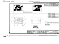
FIGURE D.2 – MAJOR COMPONENT LOCATIONS
4
1.
2.
3.
4.
CONTROL MODULE
TUNNEL MODULE
BASE MODULE
CASE WRAPAROUND
2
1
3
MULTI-WELD 350
D-4
NOTES
MULTI-WELD 350
D-4
Section E-1
Section E-1
TABLE OF CONTENTS
- THEORY OF OPERATION SECTION -
General Description .......................................................................................................................E-2
Input Power Source, Contactor and DC Buss Power Supply Board ..........................................E-2
Power Modules and Feedback ...................................................................................................E-3
Analog Control Power Supply Board and Weld Control Board .................................................E-4
Mode Selector and Output Controls............................................................................................E-5
Protection Features.....................................................................................................................E-6
Insulated Gate Bipolar Transistor (IGBT) Operation...................................................................E-7
Pulse Width Modulation ..............................................................................................................E-8
Chopper Technology Fundamentals ...........................................................................................E-9
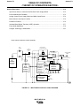
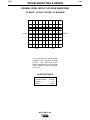
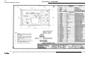
MULTI-WELD 350 BLOCK LOGIC DIAGRAM
INPUT
DIODES
LEFT AND RIGHT
CHOPPER MODULES
INPUT
CONTACTOR
CR1
IGBT
FREEWHEELING DIODE
TO ELECTRODE
CABLE
CHOPPER MODULE
+
DC
POWER
SOURCE
(EXTERNAL)
_
20
VDC
x2
CHOPPER MODULE
GATE
SIGNALS
DC
BUS
POWER
SUPPLY
BOARD
40
VDC
ANALOG
CONTROL
POWER
SUPPLY
BOARD
CURRENT FEEDBACK
TO WELD CONTROL BOARD
FREEWHEELING DIODE
IGBT
ON/OFF
MODE
SWITCH
(1/2)
REGULATED
VOLTAGES
FAN
40 VDC
15 VDC
ON/OFF
MODE
SWITCH
(1/2)
+
SHUNT
CHOKE
INPUT
CAPACITORS
AMPS
VOLTS
WELD
CONTROL
BOARD
REMOTE
RECEPTACLE
CC SLOPE
(STICK/GOUGE or PIPE)
ARC
OUTPUT
FORCE
CONTROL
CONTROL
HOT
START
THERMAL
LIGHT
CR1
COIL
PERIPHERAL
BOARD
INPUT
INDICATOR
LIGHT
WORK
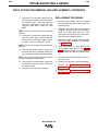
FIGURE E.1 – MULTI-WELD 350 BLOCK LOGIC DIAGRAM
MULTI-WELD 350
E-2
E-2
THEORY OF OPERATION
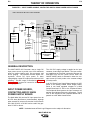
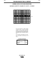
FIGURE E.2 – INPUT POWER SOURCE, CONTACTOR AND DC BUSS POWER SUPPLY BOARD
MULTI-WELD 350 BLOCK LOGIC DIAGRAM
INPUT
DIODES
LEFT AND RIGHT
CHOPPER MODULES
INPUT
CONTACTOR
CR1
IGBT
FREEWHEELING DIODE
TO ELECTRODE
CABLE
CHOPPER MODULE
+
DC
POWER
SOURCE
(EXTERNAL)
_
CHOPPER MODULE
20
VDC
x2
GATE
SIGNALS
DC
BUS
POWER
SUPPLY
BOARD
40
VDC
ANALOG
CONTROL
POWER
SUPPLY
BOARD
CURRENT FEEDBACK
TO WELD CONTROL BOARD
FREEWHEELING DIODE
IGBT
ON/OFF
MODE
SWITCH
(1/2)
REGULATED
VOLTAGES
FAN
40 VDC
15 VDC
ON/OFF
MODE
SWITCH
(1/2)
+
SHUNT
CHOKE
INPUT
CAPACITORS
AMPS
VOLTS
WELD
CONTROL
BOARD
REMOTE
RECEPTACLE
CC SLOPE
(STICK/GOUGE or PIPE)
ARC
OUTPUT
FORCE
CONTROL
CONTROL
HOT
START
THERMAL
LIGHT
CR1
COIL
PERIPHERAL
BOARD
INPUT
INDICATOR
LIGHT
WORK
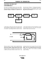
GENERAL DESCRIPTION
The MULTI-WELD 350 Converter uses a single DC
input power source to provide up to 350 continuous
amps for positive polarity stick, wire processes, and
arc-air gouging. The machine converts higher voltage/lower current DC input power to lower
voltage/higher current DC output power with over 90%
efficiency. This DC output is controlled by Chopper
Technology to produce DC current for multi-purpose
welding applications.
INPUT POWER SOURCE,
CONTACTOR AND DC BUSS
POWER SUPPLY BOARD
The +50 VDC supply voltage is applied to the input
contactor via two large input diodes. The input contactor establishes the electrical connection between the
Multi-Weld 350 and the power source when the
ON/OFF MODE switch is activated in either the constant current (CC-stick) mode or the constant voltage
(CV-wire) mode.
A 40 VDC Buss Power Supply Board supplies 40 VDC
power to the Analog Control Power Supply Board,
which in turn feeds regulated voltages to a Weld
Control Board and 15 VDC to the Peripheral Board.
The Peripheral Board powers the input contactor coil
and the input indicator light on the front panel. The 40
VDC is also supplied to the Peripheral Board and is
passed on to the Weld Control Board.
The Multi-Weld 350 receives DC input power from an
80 VDC buss Multi-Source (recommended), although
other external DC sources such as the Lincoln Electric
DC-1000, DC-655, or DC-600 can be used if they produce 50 VDC or above.
NOTE: Unshaded areas of Block Logic Diagram are the subject of discussion.
MULTI-WELD 350
E-3
E-3
THEORY OF OPERATION
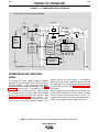
FIGURE E.3 – POWER MODULES AND FEEDBACK
MULTI-WELD 350 BLOCK LOGIC DIAGRAM
INPUT
DIODES
LEFT AND RIGHT
CHOPPER MODULES
INPUT
CONTACTOR
CR1
IGBT
FREEWHEELING DIODE
TO ELECTRODE
CABLE
CHOPPER MODULE
+
DC
POWER
SOURCE
(EXTERNAL)
_
CHOPPER MODULE
20
VDC
x2
GATE
SIGNALS
DC
BUS
POWER
SUPPLY
BOARD
40
VDC
ANALOG
CONTROL
POWER
SUPPLY
BOARD
CURRENT FEEDBACK
TO WELD CONTROL BOARD
FREEWHEELING DIODE
IGBT
ON/OFF
MODE
SWITCH
(1/2)
REGULATED
VOLTAGES
FAN
40 VDC
15 VDC
ON/OFF
MODE
SWITCH
(1/2)
+
SHUNT
CHOKE
INPUT
CAPACITORS
AMPS
VOLTS
WELD
CONTROL
BOARD
REMOTE
RECEPTACLE
CC SLOPE
(STICK/GOUGE or PIPE)
ARC
OUTPUT
FORCE
CONTROL
CONTROL
HOT
START
THERMAL
LIGHT
CR1
COIL
PERIPHERAL
BOARD
INPUT
INDICATOR
LIGHT
WORK
POWER MODULES AND FEEDBACK
The external DC source voltage is applied to parallel
capacitors incorporated within each of the two Power
(Chopper) Modules. These capacitors function as filters and as power supplies for the IGBTs. See IGBT
Operation in this section. The IGBTs act as highspeed switches operating at 20KHZ. These devices
are switched on and off by the Weld Control Board
through pulse width modulation gate signals. See
Pulse Width Modulation in this section. This
“chopped” DC output is applied through choke coils
and a shunt to the welding output terminals. The
chokes function as current filters. Free-wheeling
diodes are incorporated in the power circuit to provide
a current path for the stored energy in the chokes when
the IGBTs are turned off. See Chopper Technology in
this section.
Output voltage and current feedback information is fed
to the Weld Control Board. This information is sensed
from the output terminal circuits and the shunt. The
feedback information is processed by the Weld Control
Board, which regulates output voltage and current.
NOTE: Unshaded areas of Block Logic Diagram are the subject of discussion.
MULTI-WELD 350
E-4
E-4
THEORY OF OPERATION
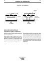
FIGURE E-4 – ANALOG CONTROL POWER SUPPLY BOARD AND WELD CONTROL BOARD
MULTI-WELD 350 BLOCK LOGIC DIAGRAM
INPUT
DIODES
LEFT AND RIGHT
CHOPPER MODULES
INPUT
CONTACTOR
CR1
IGBT
FREEWHEELING DIODE
TO ELECTRODE
CABLE
CHOPPER MODULE
+
DC
POWER
SOURCE
(EXTERNAL)
_
CHOPPER MODULE
20
VDC
x2
GATE
SIGNALS
DC
BUS
POWER
SUPPLY
BOARD
40
VDC
ANALOG
CONTROL
POWER
SUPPLY
BOARD
CURRENT FEEDBACK
TO WELD CONTROL BOARD
FREEWHEELING DIODE
IGBT
ON/OFF
MODE
SWITCH
(1/2)
REGULATED
VOLTAGES
FAN
40 VDC
15 VDC
ON/OFF
MODE
SWITCH
(1/2)
+
SHUNT
CHOKE
INPUT
CAPACITORS
AMPS
VOLTS
WELD
CONTROL
BOARD
REMOTE
RECEPTACLE
CC SLOPE
(STICK/GOUGE or PIPE)
ARC
OUTPUT
FORCE
CONTROL
CONTROL
HOT
START
THERMAL
LIGHT
CR1
COIL
PERIPHERAL
BOARD
INPUT
INDICATOR
LIGHT
WORK
ANALOG CONTROL POWER
SUPPLY BOARD AND WELD
CONTROL BOARD
The Analog Control Power Supply Board, which is powered by 40 VDC delivered from the DC Buss Power
Supply Board, supplies various regulated DC voltages
to operate the Weld Control Board circuitry. It also provides two regulated 20 VDC supplies to operate the
electronics on the Chopper Module Boards and applies
a 15 VDC supply to the Peripheral Board.
The Weld Control Board monitors the operator controls
(arc control, output control, hot start control, mode
selector switch, CC Slope switch and the remote control receptacle). It compares these commands to the
current and voltage feedback information it receives
from the shunt and output terminal circuits. The circuitry on the Weld Control Board determines how the
output should be controlled to optimize welding results,
and it sends the correct PWM gate signals to the IGBT
driver circuits. The Weld Control Board commands the
voltmeter and ammeter, which display both preset and
actual (while welding) voltage and current. The Weld
Control Board also controls the cooling fan motor and
the thermal indicator (light).
NOTE: Unshaded areas of Block Logic Diagram are the subject of discussion.
MULTI-WELD 350
E-5
E-5
THEORY OF OPERATION
FIGURE E.5 – MODE SELECTOR AND OUTPUT CONTROLS
MULTI-WELD 350 BLOCK LOGIC DIAGRAM
INPUT
DIODES
LEFT AND RIGHT
CHOPPER MODULES
INPUT
CONTACTOR
CR1
IGBT
FREEWHEELING DIODE
TO ELECTRODE
CABLE
CHOPPER MODULE
+
DC
POWER
SOURCE
(EXTERNAL)
_
CHOPPER MODULE
20
VDC
x2
GATE
SIGNALS
DC
BUS
POWER
SUPPLY
BOARD
ANALOG
CONTROL
POWER
SUPPLY
BOARD
40
VDC
CURRENT FEEDBACK
TO WELD CONTROL BOARD
FREEWHEELING DIODE
IGBT
ON/OFF
MODE
SWITCH
(1/2)
REGULATED
VOLTAGES
FAN
40 VDC
15 VDC
ON/OFF
MODE
SWITCH
(1/2)
+
SHUNT
CHOKE
INPUT
CAPACITORS
AMPS
VOLTS
WELD
CONTROL
BOARD
REMOTE
RECEPTACLE
CC SLOPE
(STICK/GOUGE or PIPE)
ARC
OUTPUT
FORCE
CONTROL
CONTROL
HOT
START
THERMAL
LIGHT
CR1
COIL
PERIPHERAL
BOARD
INPUT
INDICATOR
LIGHT
WORK
MODE SELECTOR AND OUTPUT
CONTROLS
In CC mode, machine output is at open circuit voltage.
The OUTPUT control presets amps in the 30 to 350 A
range and then adjusts actual welding current to match
the preset when welding. In CV mode, machine output
is at the voltage level set at the OUTPUT control. The
OUTPUT control presets volts, then adjusts the actual
arc voltage to match the preset when welding.
A HOT START control is provided to enhance arc starting with an adjustable output “boost” in either CC or CV
mode. The ARC FORCE control (CC mode only) provides extra weld current to prevent electrode “stubbing”
An additional CC SLOPE switch improves “fast-freeze”
stick electrode performance during vertical pipe welding when set to the PIPE position.
NOTE: Unshaded areas of Block Logic Diagram are the subject of discussion.
MULTI-WELD 350
E-6
E-6
THEORY OF OPERATION
PROTECTION FEATURES
OVER-CURRENT PROTECTION
The Multi-Weld 350 design features electronic protection systems to help assure reliable operation even
under adverse conditions. These systems include:
The maximum output current of the Multi-Weld 350 is
electronically limited so as not to exceed 375 amps
average and 500 amps peak to protect internal power
components. When the current load starts to exceed
these limits, the output is reduced (lower voltage) to
sustain maximum levels until the current is reduced,
even to a shorted output.
FAN AS NEEDED (F.A.N.)
The cooling fan will turn on when the arc starts and
remain on for about a minute after the arc is out to cool
down the power components.
This feature electronically controls the fan so it does
not run continuously when the power switch is turned
on. This will minimize the amount of contaminate and
clogging debris that may be drawn into the converter.
The “Central-Air” system design intakes lower velocity
air through the higher side louvers and blows it out
through the lower back louvers with higher velocity.
OVER-TEMPERATURE SHUTDOWN
The Multi-Weld 350 has a temperature sensing thermostat on the input diode heat sink to protect the
power components within the converter from overheating. If this thermostat temperature exceeds about 95
degrees C (203 degrees F), the converter will electronically shut off the output and turn on the Thermal
Shutdown (yellow) Light until the thermostat is cooled
enough to reset.
CAUTION
When the thermostat resets, the converter output will
reactivate. Switching OFF input power prevents reactivation but also shuts off the cooling fan, which prolongs the reset time.
During over-temperature shutdown the panel displays
will be appropriate for the non-welding mode.
However, the fan will remain running and the Thermal
Shutdown Light will be lit until reset.
Prolonged output at this maximum current limit level
may eventually over heat the converter’s internal
power components, causing over-temperature shutdown.
Short circuit protection is also provided to reduce maximum output current to about 200 amps if the output
voltage is reduced, by loading or current limiting, to
below 14 volts for over 7 seconds (indicating a shorted
output). The output current must be interrupted to
reset this reduced protective level.
This maximum 200 amp short circuit level will allow
using the Multi-Weld 350 for “pipe-thawing” applications without causing over-temperature shutdown.
CAUTION
When the contactor recloses, the converter output will
reactivate. Switching OFF input power prevents unexpected reactivation.
This feature protects internal components of the converter from excessive voltage levels.
OVER-VOLTAGE PROTECTION
The Multi-Weld 350 input contactor will open if the input
supply voltage is above 113 VDC, and it will automatically reclose if the voltage drops back to 113 VDC.
During over-voltage shutdown the panel displays will
be as appropriate for the non-welding mode.
MULTI-WELD 350
E-7
E-7
THEORY OF OPERATION
FIGURE E.6 – IGBT OPERATION
POSITIVE
VOLTAGE
APPLIED
SOURCE
n+
GATE
SOURCE
n+
n+
GATE
n+
p
BODY REGION
p
BODY REGION
n-
DRAIN DRIFT REGION
n-
DRAIN DRIFT REGION
n+
BUFFER LAYER
n+
BUFFER LAYER
p+
INJECTING LAYER
p+
INJECTING LAYER
DRAIN
DRAIN
B. ACTIVE
A. PASSIVE
INSULATED GATE BIPOLAR
TRANSISTOR (IGBT) OPERATION
An IGBT is a type of transistor. IGBTs are semiconductors well suited for high frequency switching and
high current applications.
Drawing A shows an IGBT in a passive mode. There is
no gate signal, zero volts relative to the source, and
therefore, no current flow. The drain terminal of the
IGBT may be connected to a voltage supply; but since
there is no conduction the circuit will not supply current
to components connected to the source. The circuit is
turned off like a light switch in the OFF position.
Drawing B shows the IGBT in an active mode. When
the gate signal, a positive DC voltage relative to the
source, is applied to the gate terminal of the IGBT, it is
capable of conducting current. A voltage supply connected to the drain terminal will allow the IGBT to conduct and supply current to circuit components coupled
to the source. Current will flow through the conducting
IGBT to downstream components as long as the positive gate signal is present. This is similar to turning ON
a light switch.
MULTI-WELD 350
E-8
THEORY OF OPERATION
E-8
FIGURE E.7 – TYPICAL IGBT OUTPUTS
MINIMUM OUTPUT
2 sec
48
50
sec
sec
MAXIMUM OUTPUT
48
sec
50 sec
PULSE WIDTH MODULATION
The term PULSE WIDTH MODULATION is used to
describe how much time is devoted to conduction in the
cycle. Changing the pulse width is known as MODULATION. Pulse Width Modulation (PWM) is the varying
of the pulse width over the allowed range of a cycle to
affect the output of the machine.
MINIMUM OUTPUT
By controlling the duration of the gate signal, the IGBT
is turned on and off for different durations during a
cycle. The top drawing shows the minimum output signal possible over a 50-microsecond time period.
The shaded portion of the signal represents the IGBT,
conducting for 2 microseconds. Since only 2 microseconds of the 50-microsecond time period is devoted to
conducting, the output power is minimized.
MAXIMUM OUTPUT
By holding the gate signals on for 48 microseconds and
allowing only 2 microseconds of off time during the 50microsecond cycle, the output is maximized. The darkened area under the min. curve can be compared to
the darkened area under the max. curve. The more
darkened area, the more power is present.
MULTI-WELD 350
E-9
E-9
THEORY OF OPERATION
CHOPPER TECHNOLOGY
FUNDAMENTALS
The new era of welding machines such as the MultiWeld 350 employ a technology whereby a DC source
is turned on and off (chopped up) at high speed, then
smoothed through an inductor to control an arc.
EXTERNAL DC
SOURCE
SOLID STATE
SWITCH
Hence the name “Chopper.” The biggest advantage of
chopper technology is the high-speed control of the
arc, similar to how inverter machines operate. A block
diagram for this is as follows:
INDUCTOR
AND DIODE
ARC
ARC
CONTROL
In this system, current from a DC source such as the
MULTI-SOURCE is applied through a solid state switch
to an inductor. By turning the switch on and off, current
in the inductor and the arc can be controlled. The following diagram depicts the current flow in the system
when the switch is open and closed:
INDUCTOR
SWITCH
70-80VDC
ARC
DIODE
CURRENT WITH SWITCH OPEN
CURRENT WITH SWITCH CLOSED
When the switch is closed, current is applied through
the inductor to the arc. When the switch opens, current
stored in the inductor sustains flow in the arc and
through the diode. The repetition rate of switch closure
is 20Khz, which allows ultra-fast control of the arc. By
varying the ratio of on time versus off time of the switch
(Duty Cycle), the current applied to the arc is controlled. This is the basis for Chopper Technology:
Controlling the switch in such a way as to produce
superior welding.
MULTI-WELD 350
E-10
NOTES
MULTI-WELD 350
E-10
Section F-1
TABLE OF CONTENTS
- TROUBLESHOOTING & REPAIR SECTION -
Troubleshooting & Repair Section......................................................................................Section F
How to Use Troubleshooting Guide ...........................................................................................F-2
PC Board Troubleshooting Procedures ......................................................................................F-3
Troubleshooting Guide ....................................................................................................F-4 - F-12
Test Procedures .......................................................................................................................F-13
Case Cover Assembly Removal and Replacement Procedure .........................................F-13
Power Module Capacitor Discharge Procedure ................................................................F-15
Input Contactor Coil Resistance and Supply Voltage Test .................................................F-17
Analog Control Power Supply PC Board Test ....................................................................F-20
DC Buss Power Supply PC Board Test ..............................................................................F-23
Chopper PC Board Input Voltages and Resistance Tests ..................................................F-26
Oscilloscope Waveforms ..........................................................................................................F-29
Normal Open Circuit Voltage Waveform (CC Mode) –
Input Voltage Applied 75 VDC ...........................................................................................F-29
Normal Open Circuit Voltage Waveform (CV Mode) –
Output Control at Maximum................................................................................................F-30
Normal Weld Voltage Waveform (CC Stick Mode) –
Machine Loaded to 350 Amps at 34 Volts ..........................................................................F-31
Normal Weld Voltage Waveform (CV Mode) –
Machine Loaded to 350 Amps at 34 Volts ..........................................................................F-32
Normal Open Circuit Voltage Waveform (CV Mode) –
Output Control at Maximum................................................................................................F-33
Replacement Procedures .........................................................................................................F-34
Case Front Assembly Removal and Replacement .............................................................F-34
Weld Control Board Removal and Replacement ...............................................................F-36
Amps/Volts Digital Meter and Potentiometer Removal and Replacement .........................F-39
Input Contactor Removal and Replacement.......................................................................F-42
Input Diode Removal and Replacement.............................................................................F-45
Fan Motor Assembly Removal and Replacement ..............................................................F-48
Power Capacitor Removal and Replacement.....................................................................F-51
Chopper PC Board and Diode Module Removal and Replacement .................................F-54
Diode Module Removal and Replacement .........................................................................F-57
Retest After Repair ...................................................................................................................F-60
MULTI-WELD 350
Section F-1
F-2
TROUBLESHOOTING & REPAIR
HOW TO USE TROUBLESHOOTING GUIDE
WARNING
Service and repair should be performed by only Lincoln Electric Factory Trained Personnel.
Unauthorized repairs performed on this equipment may result in danger to the technician and machine
operator and will invalidate your factory warranty. For your safety and to avoid Electrical Shock, please
observe all safety notes and precautions detailed throughout this manual.
This Troubleshooting Guide is provided to help
you locate and repair possible machine malfunctions. Simply follow the three-step procedure listed below.
Step 1. LOCATE PROBLEM (SYMPTOM). Look
under the column labeled “PROBLEM” (SYMPTOMS). This column describes possible symptoms that the machine may exhibit. Find the listing that best describes the symptom that the
machine is exhibiting. Symptoms are grouped
into four main categories: Output Problems,
Function Problems and Welding Problems.
Step 2. PERFORM EXTERNAL TESTS. The
second column, labeled “POSSIBLE AREAS OF
MISADJUSTMENT(S)”, lists the obvious external
possibilities that may contribute to the machine
symptom. Perform these tests/checks in the
order listed. In general, these tests can be conducted without removing the case cover.
Step 3. PERFORM COMPONENT TESTS. The
last column, labeled “Recommended Course of
Action” lists the most likely components that may
have failed in your machine. It also specifies the
appropriate test procedure to verify that the subject component is either good or bad. If there are
a number of possible components, check the
components in the order listed to eliminate one
possibility at a time until you locate the cause of
your problem.
All of the referenced test procedures referred to in
the Troubleshooting Guide are described in detail
at the end of this section.
Refer to the
Troubleshooting and Repair Table of Contents to
locate each specific Test Procedure. All of the
referred to test points, components, terminal
strips, etc., can be found on the referenced electrical wiring diagrams and schematics. Refer to
the Electrical Diagrams Section Table of Contents
to locate the appropriate diagram.
CAUTION
If for any reason you do not understand the test procedures or are unable to perform the test/repairs
safely, contact the Lincoln Electric Service Department for electrical troubleshooting assistance before
you proceed. Call 1-800-833-9353.
MULTI-WELD 350
F-2
F-3
TROUBLESHOOTING & REPAIR
F-3
PC BOARD TROUBLESHOOTING PROCEDURES
WARNING
ELECTRIC SHOCK can kill.
Have an electrician install and service
this equipment. Turn the machine OFF
before working on equipment. Do not
touch electrically hot parts.
Sometimes machine failures appear to be due to PC
board failures. These problems can sometimes be
traced to poor electrical connections. To avoid problems when troubleshooting and replacing PC boards,
please use the following procedure:
1. Determine to the best of your technical ability that
the PC board is the most likely component causing
the failure symptom.
2. Check for loose connections at the PC board to
assure that the PC board is properly connected.
3. If the problem persists, replace the suspect PC
board using standard practices to avoid static electrical damage and electrical shock. Read the warning inside the static resistant bag and perform the
following procedures:
• Remove the PC Board from the static-shielding bag
and place it directly into the equipment. Don’t set the
PC Board on or near paper, plastic or cloth which
could have a static charge. If the PC Board can’t be
installed immediately, put it back in the staticshielding bag.
• If the PC Board uses protective shorting jumpers,
don’t remove them until installation is complete.
• If you return a PC Board to The Lincoln Electric
Company for credit, it must be in the static-shielding
bag. This will prevent further damage and allow proper failure analysis.
4. Test the machine to determine if the failure symptom has been corrected by the replacement PC
board.
NOTE: Allow the machine to heat up so that all electrical components can reach their operating temperature.
5. Remove the replacement PC board and substitute
it with the original PC board to recreate the original
problem.
a. If the original problem does not reappear
by substituting the original board, then the
PC board was not the problem. Continue
to look for bad connections in the control
wiring harness, junction blocks, and terminal strips.
PC Board can be damaged by
static electricity.
ATTENTION
Static-Sensitive
Devices
Handle only at
Static-Safe
Workstations
Reusable
Container
Do Not Destroy
• Remove your body’s static charge
before opening the static-shielding
bag. Wear an anti-static wrist
strap. For safety, use a 1 Meg
ohm resistive cord connected to a
grounded part of the equipment
frame.
• If you don’t have a wrist strap,
touch an unpainted, grounded,
part of the equipment frame. Keep
touching the frame to prevent static build-up. Be sure not to touch
any electrically live parts at the
same time.
b. If the original problem is recreated by
substitution of the original board, then
PC board was the problem. Reinstall
replacement PC board and test
machine.
the
the
the
the
6. Always indicate that this procedure was followed
when warranty reports are to be submitted.
NOTE: Following this procedure and writing on the
warranty report, “INSTALLED AND SWITCHED PC
BOARDS TO VERIFY PROBLEM,” will help avoid
denial of legitimate PC board warranty claims.
• Tools which come in contact with the PC Board must
be either conductive, anti-static or static-dissipative.
MULTI-WELD 350
F-4
TROUBLESHOOTING & REPAIR
TROUBLESHOOTING GUIDE
Observe Safety Guidelines
detailed in the beginning of this manual.
PROBLEMS
(SYMPTOMS)
F-4
POSSIBLE AREAS OF
MISADJUSTMENT(S)
RECOMMENDED
COURSE OF ACTION
OUTPUT PROBLEMS
Major physical or electrical damage
is evident.
1. Contact your local Lincoln
Authorized
Field
Service
Facility.
1. Contact the Lincoln Electric
Service Department at 1-800833-9353 (WELD)
The Multi-Weld 350 is completely
dead. The meters do not light and
the input contactor does not activate when the ON/OFF Mode
Selector switch is turned on.
1. Make sure the power source is
working properly and supplying
at least 50VDC to the MultiWeld 350. The electrode cable
must be positive polarity and the
work cable negative polarity.
1. Measure the input voltage to the
Multi-Weld 350. It must be
between 50 and 113VDC.
2. Check the electrode and work
cables for loose or faulty connections.
2. The ON/OFF Mode Selector
switch (S1) may be faulty.
Check and replace if faulty. See
the Wiring Diagram. Also check
associated wiring.
3. The input diode D1/D2 may be
open. Check. See the Wiring
Diagram.
4. Perform the DC Buss Supply
Board Test.
5. Perform the Analog Control
Power Supply Board Test.
6. The Weld Control Board may be
faulty. Replace.
CAUTION
If for any reason you do not understand the test procedures or are unable to perform the test/repairs safely,
contact the Lincoln Electric Service Department for electrical troubleshooting assistance before you proceed. Call
1-800-833-9353.
MULTI-WELD 350
F-5
TROUBLESHOOTING & REPAIR
TROUBLESHOOTING GUIDE
PROBLEMS
(SYMPTOMS)
F-5
Observe Safety Guidelines
detailed in the beginning of this manual.
POSSIBLE AREAS OF
MISADJUSTMENT(S)
RECOMMENDED
COURSE OF ACTION
OUTPUT PROBLEMS
The meters light, but the input contactor does not activate when the
ON/OFF Mode Selector switch is
turned on. The Multi-Weld 350
does not have output.
1. Make sure the input voltage
applied to the Multi-Weld 350 is
not greater than 113VDC.
1. Check leads 330 and 303A for
loose or faulty connections.
See the Wiring Diagram.
2. Perform the Input Contactor
Coil Resistance and Supply
Voltage Test.
3. The Peripheral Board may be
faulty.
4. The Weld Control Board may be
faulty.
The Thermal Light is on. The MultiWeld 350 does not have output.
The fan operates normally.
1. The output rating of the
machine may be exceeded.
See
the
Technical
Specifications.
2. Wait until the machine cools and
the Thermal Light goes out. The
machineís output should be
restored.
1. The Thermostat, located on the
input diode heat sink, may be
faulty.
2. Check leads 306, 307, 206, 207
and plugs J22 and J11 for loose
or faulty connections. See the
Wiring Diagram.
CAUTION
If for any reason you do not understand the test procedures or are unable to perform the test/repairs safely,
contact the Lincoln Electric Service Department for electrical troubleshooting assistance before you proceed. Call
1-800-833-9353.
MULTI-WELD 350
F-6
TROUBLESHOOTING & REPAIR
TROUBLESHOOTING GUIDE
Observe Safety Guidelines
detailed in the beginning of this manual.
PROBLEMS
(SYMPTOMS)
F-6
POSSIBLE AREAS OF
MISADJUSTMENT(S)
RECOMMENDED
COURSE OF ACTION
OUTPUT PROBLEMS
The Multi-Weld 350 does not have
output. The meters turn on, the
input contactor activates and the
Thermal light is off.
1. Check the welding cables for
loose or faulty connections.
1. Check for loose or faulty connections at the Control box, the
Chopper boards, and the
Analog Power Supply Board.
See the Wiring Diagram.
2. Check the heavy current carrying leads at the choke, the
chopper boards, the shunt and
the output terminals for loose or
faulty connections. See the
Wiring Diagram.
3. Perform the Chopper Board
Input Voltage and Resistance
Test.
4. Perform the Analog Control
Power Supply Board Test.
5. The Weld Control Board may be
faulty. Replace.
CAUTION
If for any reason you do not understand the test procedures or are unable to perform the test/repairs safely,
contact the Lincoln Electric Service Department for electrical troubleshooting assistance before you proceed. Call
1-800-833-9353.
MULTI-WELD 350
F-7
TROUBLESHOOTING & REPAIR
TROUBLESHOOTING GUIDE
PROBLEMS
(SYMPTOMS)
F-7
Observe Safety Guidelines
detailed in the beginning of this manual.
POSSIBLE AREAS OF
MISADJUSTMENT(S)
RECOMMENDED
COURSE OF ACTION
FUNCTION PROBLEMS
The preset amps (CC mode) or
volts (CV mode) are not adjustable.
1. The panel Output Control is disabled when a remote control
device is plugged into the 6-pin
remote receptacle.
1. The Output Control (R1) may be
faulty. Check or replace. Also
check associated leads for
loose or faulty connections.
2. Check all the plug connections
to the Weld Control Board for
loose or faulty connections.
See the Wiring Diagram.
3. The Weld Control Board may be
faulty. Replace.
The preset range is not correct.
1. The panel Output Control is disabled when a remote control
device is plugged into the 6-pin
remote receptacle.
1. Make sure plug P3 is connected
securely to receptacle J3 on the
Weld Control Board. See the
Wiring Diagram. Make certain
all the jumper leads are in place.
2. Check all the plug connections
to the Weld Control Board for
loose or faulty connections.
See the Wiring Diagram.
3. The Weld Control Board may be
faulty. Replace.
CAUTION
If for any reason you do not understand the test procedures or are unable to perform the test/repairs safely,
contact the Lincoln Electric Service Department for electrical troubleshooting assistance before you proceed. Call
1-800-833-9353.
MULTI-WELD 350
F-8
TROUBLESHOOTING & REPAIR
TROUBLESHOOTING GUIDE
Observe Safety Guidelines
detailed in the beginning of this manual.
PROBLEMS
(SYMPTOMS)
F-8
POSSIBLE AREAS OF
MISADJUSTMENT(S)
RECOMMENDED
COURSE OF ACTION
FUNCTION PROBLEMS
The meters do not light in either CV
or CC modes.
1. In the CC mode, only the AMPS
meter will light. In the CV mode,
only the VOLTS meter will light.
1. Check all the plug connections
to the Weld Control Board for
loose or faulty connections.
See the Wiring Diagram.
2. Check the leads and connections between the meters and
the Weld Control Board. See
the Wiring Diagram.
3. Perform the Analog Control
Power Supply Board Test.
4. The meters may be faulty.
5. The Weld Control Board may be
faulty. Replace.
One or both of the meter’s readings
are not accurate.
1. Make sure the test or external
meter is reliable and accurate.
1. Check shunt feedback leads
R326, 327, R226, 227, plugs
P21 and P6 for loose or faulty
connections. See the Wiring
Diagram.
2. Check the integrity of lead 237
at plug P12 on the Weld Control
Board and also at plug P31 on
the Peripheral Board.
3. See the Digital Meter Calibration and Adjustment Test in
the Maintenance section.
4. Perform the Analog Control
Power Supply Board Test.
5. The Weld Control Board may be
faulty. Replace.
CAUTION
If for any reason you do not understand the test procedures or are unable to perform the test/repairs safely,
contact the Lincoln Electric Service Department for electrical troubleshooting assistance before you proceed. Call
1-800-833-9353.
MULTI-WELD 350
F-9
TROUBLESHOOTING & REPAIR
TROUBLESHOOTING GUIDE
PROBLEMS
(SYMPTOMS)
F-9
Observe Safety Guidelines
detailed in the beginning of this manual.
POSSIBLE AREAS OF
MISADJUSTMENT(S)
RECOMMENDED
COURSE OF ACTION
FUNCTION PROBLEMS
The fan motor does not run when
the machine is turned on.
1. Normal operation. The MultiWeld 350 utilizes a Fan On
Demand system.
The fan
should activate when welding.
The fan does not run when welding.
1. The fan should turn on when the
arc starts and remain on for
about a minute after the arc is
out.
1. Carefully check for approximately 40VDC at the fan motor
leads (303+ to 300-). This test
must be performed while the
machine is connected to a resistive load or welding. If the
40VDC is NOT present, check
the associated leads and plugs
for loose or faulty connections.
See the Wiring Diagram. If the
correct voltage IS present and
the fan is not running, the fan
motor may be faulty.
2. If the correct voltage (40VDC) is
not present in the above test,
perform the DC Buss Supply
Board Test.
3. The Weld Control Board may be
faulty. Replace.
CAUTION
If for any reason you do not understand the test procedures or are unable to perform the test/repairs safely,
contact the Lincoln Electric Service Department for electrical troubleshooting assistance before you proceed. Call
1-800-833-9353.
MULTI-WELD 350
F-10
TROUBLESHOOTING & REPAIR
TROUBLESHOOTING GUIDE
Observe Safety Guidelines
detailed in the beginning of this manual.
PROBLEMS
(SYMPTOMS)
F-10
POSSIBLE AREAS OF
MISADJUSTMENT(S)
RECOMMENDED
COURSE OF ACTION
WELDING PROBLEMS
The welding output is high with no
control.
1. Check all input and output
cables for shorts. Check the
positive input and output cables
for “grounded” connections to
the machine’s case.
1. Check shunt feedback leads
R326, 327, R226, 227, plugs
P21 and P6, for loose or faulty
connections. See the Wiring
Diagram.
2. Check the continuity of leads
401, 301, 201, plugs P20, P22
and P31.
See the Wiring
Diagram.
3. Check the Output Control R1
and the associated leads. See
the Wiring Diagram.
4. The Weld Control Board may be
Faulty.
No control of welding output.
1. The panel Output Control is disabled when a remote control
device is plugged into the 6-pin
remote receptacle.
2. Check the welding cables for
loose or faulty connections.
1. Check the Output Control (R1)
and the associated leads for
loose or faulty connections.
2. Check all the plug connections
to the Weld Control Board for
loose or faulty connections.
See the Wiring Diagram.
3. The Weld Control Board may be
faulty. Replace.
CAUTION
If for any reason you do not understand the test procedures or are unable to perform the test/repairs safely,
contact the Lincoln Electric Service Department for electrical troubleshooting assistance before you proceed. Call
1-800-833-9353.
MULTI-WELD 350
F-11
TROUBLESHOOTING & REPAIR
TROUBLESHOOTING GUIDE
PROBLEMS
(SYMPTOMS)
F-11
Observe Safety Guidelines
detailed in the beginning of this manual.
POSSIBLE AREAS OF
MISADJUSTMENT(S)
RECOMMENDED
COURSE OF ACTION
WELDING PROBLEMS
When welding in the Stick Mode,
the current changes with arc
length.
1. Make sure the machine settings
are correct for the process
being used. When stick welding, the CC Slope Switch (S2)
should be in the Stick/Gouge
position.
2. Check the welding cables for
loose or faulty connections.
When using “fast freeze” type electrodes such as E6010 or E7010,
the welding performance is poor.
1. Make sure the machine settings
are correct for the process
being used. When stick welding
with “fast freeze” type electrodes, the CC Slope Switch
(S2) should be in the Pipe position.
2. Check the welding cables for
loose or faulty connections.
1. Check the CC Slope Switch
(S2) and the associated lead
connections.
2. Check all the plug connections
to the Weld Control Board for
loose or faulty connections.
See the Wiring Diagram
3. The Weld Control Board may be
faulty. Replace.
1. Check the CC Slope Switch
(S2) and the associated lead
connections.
2. Check all the plug connections
to the Weld Control Board for
loose or faulty connections.
See the Wiring Diagram.
3. The Weld Control Board may be
faulty. Replace.
CAUTION
If for any reason you do not understand the test procedures or are unable to perform the test/repairs safely,
contact the Lincoln Electric Service Department for electrical troubleshooting assistance before you proceed. Call
1-800-833-9353.
MULTI-WELD 350
F-12
TROUBLESHOOTING & REPAIR
TROUBLESHOOTING GUIDE
Observe Safety Guidelines
detailed in the beginning of this manual.
PROBLEMS
(SYMPTOMS)
F-12
POSSIBLE AREAS OF
MISADJUSTMENT(S)
RECOMMENDED
COURSE OF ACTION
WELDING PROBLEMS
The arc starting is not satisfactory.
1. The Hot Start Control may not
be set correctly for the process
being used.
2. Make sure the Output Control is
adjusted correctly for the
process being used.
1. Check the Hot Start Control
(R2) and associated leads and
connections. Note: The Arc
Force Control and Hot Start
Control are interchangeable and
may be switched to aid in troubleshooting. See the Wiring
Diagram.
2. The Weld Control Board may be
faulty.
When stick welding the electrode
“stubs”.
1. The Arc Force Control may not
be set correctly for the process
being used. Increase the Arc
Force.
2. Make sure the Output Control is
adjusted correctly for the
process being used.
3. Check the welding cables for
loose or faulty connections.
1. Check the Arc Force Control
(R3) and associated leads and
connections. Note: The Arc
Force Control and Hot Start
Control are interchangeable and
may be switched to aid in troubleshooting. See the Wiring
Diagram.
2. The Weld Control Board may be
faulty.
CAUTION
If for any reason you do not understand the test procedures or are unable to perform the test/repairs safely,
contact the Lincoln Electric Service Department for electrical troubleshooting assistance before you proceed. Call
1-800-833-9353.
MULTI-WELD 350
F-13
TROUBLESHOOTING & REPAIR
CASE COVER ASSEMBLY REMOVAL
AND REPLACEMENT PROCEDURE
WARNING
Service and repair should be performed by only Lincoln Electric factory trained personnel.
Unauthorized repairs performed on this equipment may result in danger to the technician
or machine operator and will invalidate your factory warranty. For your safety and to avoid
electrical shock, please observe all safety notes and precautions detailed throughout this
manual.
If for any reason you do not understand the test procedures or are unable to perform the
test/repairs safely, contact the Lincoln Electric Service Department for electrical troubleshooting assistance before you proceed. Call 1-800-833-9353 (WELD).
TEST DESCRIPTION
This procedure will aid the technician in the removal and replacement of the case sheet
metal cover.
MATERIALS NEEDED
3/8" Wrench or socket wrench
This procedure should take approximately 5 minutes to perform.
MULTI-WELD 350
F-13
F-14
TROUBLESHOOTING & REPAIR
F-14
CASE COVER ASSEMBLY REMOVAL
AND REPLACEMENT PROCEDURE (CONTINUED)
FIGURE F.1 – COVER REMOVAL DETAILS
CASE COVER
350
LD
WE
TIUL
M
FRONT
TOROID
RING
LOCATION
SCREW
HOLE (13)
AM
PS
A
VO
LTS
LIN
CO
LN
ELE
CTR
IC
V
MU
LT
I-W
EL
D
IN
PU
35
0
T
CH
OP
PE
R
TE
CH
NO
LO
GY
WO
EL
RK
EC
TR
OD
E
REMOVAL PROCEDURE
REPLACEMENT PROCEDURE
1. Set the CC/CV power switch to OFF.
1. Be sure that the toroid rings on the top of
the tunnel assembly are lying flat and will
not restrict placement of the machine cover.
See Figure F.1.
2. Remove input power to the machine.
WARNING
2. The cover fits on in one direction only.
Verify front/back orientation, then carefully
lower the cover into place.
ELECTRIC SHOCK can kill.
Disconnect input power before removing the
case cover and performing tests or making
repairs to the machine.
3. Install the 13 sheet metal screws that hold
the case cover in place.
3. Using the 3/8" nut driver, remove the 13
sheet metal screws holding the case cover
assembly in place.
4. Carefully lift the cover off the machine.
MULTI-WELD 350
F-15
TROUBLESHOOTING & REPAIR
POWER MODULE CAPACITOR DISCHARGE PROCEDURE
WARNING
Service and repair should be performed by only Lincoln Electric factory trained personnel.
Unauthorized repairs performed on this equipment may result in danger to the technician
or machine operator and will invalidate your factory warranty. For your safety and to avoid
electrical shock, please observe all safety notes and precautions detailed throughout this
manual.
If for any reason you do not understand the test procedures or are unable to perform the
test/repairs safely, contact the Lincoln Electric Service Department for electrical troubleshooting assistance before you proceed. Call 1-800-833-9353 (WELD).
TEST DESCRIPTION
This procedure will insure that the large capacitor in each chopper power module has
been discharged. This procedure should be performed whenever work is to be attempted on or near the power modules.
MATERIALS NEEDED
3/8" Wrench or socket wrench
Volt/Ohmmeter
Resistor (25-1000 ohms and 25 watts minimum)
Jumper leads
This procedure should take approximately 15 minutes to perform.
MULTI-WELD 350
F-15
F-16
F-16
TROUBLESHOOTING & REPAIR
POWER MODULE CAPACITOR DISCHARGE PROCEDURE (CONTINUED)
FIGURE F.2 – POWER MODULE CAPACITOR TERMINAL DISCHARGE
AM
PS
A
VO
LTS
LIN
C
ELOLN
EC
TR
IC
V
MU
LT
I-W
EL
D
IN
PU
POWER
MODULE
CAPACITOR
TERMINALS
35
0
T
CH
OP
PE
R
TE
CH
NO
LO
GY
WO
EL
RK
EC
TR
OD
E
PROCEDURE
1. Set the CC/CV power switch to OFF.
2. Remove input power to the machine.
WARNING
ELECTRIC SHOCK can kill.
Disconnect input power before removing the
case cover and performing tests or making
repairs to the machine.
3. Perform the Case Cover Assembly
Removal procedure.
4. Locate the power module capacitors on the
right and left sides of the tunnel assembly.
See Figure F.2.
5. Using the resistor and jumper leads, CAREFULLY discharge the capacitor terminals.
NEVER USE A SHORTING STRAP FOR
THIS PURPOSE. DO NOT TOUCH THE
TERMINALS WITH YOUR BARE HANDS.
Repeat the procedure for the second
capacitor.
6. Using the volt/ohmmeter, check the voltage
across the capacitor terminals. It should be
zero volts.
MULTI-WELD 350
F-17
TROUBLESHOOTING & REPAIR
F-17
INPUT CONTACTOR COIL RESISTANCE AND SUPPLY VOLTAGE TEST
WARNING
Service and repair should be performed by only Lincoln Electric factory trained personnel.
Unauthorized repairs performed on this equipment may result in danger to the technician
or machine operator and will invalidate your factory warranty. For your safety and to avoid
electrical shock, please observe all safety notes and precautions detailed throughout this
manual.
If for any reason you do not understand the test procedures or are unable to perform the
test/repairs safely, contact the Lincoln Electric Service Department for electrical troubleshooting assistance before you proceed. Call 1-800-833-9353 (WELD).
TEST DESCRIPTION
This test will determine if the input contactor is functioning properly.
MATERIALS NEEDED
Volt/Ohmmeter
3/8" Nut driver
Needle nose pliers
Wiring Diagram
External, isolated 40 VDC power supply
This procedure should take approximately 40 minutes to perform.
MULTI-WELD 350
F-18
TROUBLESHOOTING & REPAIR
F-18
INPUT CONTACTOR COIL RESISTANCE AND
SUPPLY VOLTAGE TEST (CONTINUED)
FIGURE F.3 – INPUT CONTACTOR DETAILS
LEADS
#303A
#330
COIL TEST PROCEDURE
1. Set the CC/CV power switch to OFF.
2. Remove input power to the machine.
4. Perform the Power Module Capacitor
Discharge procedure.
5. Locate the input contactor and coil leads
#303A and #330. See Figure F.3.
WARNING
6. Label and disconnect leads #303A and
#330 at their in-line connectors.
ELECTRIC SHOCK can kill.
Disconnect input power before removing the
case cover and performing tests or making
repairs to the machine.
3. Perform the Case Cover Removal procedure.
7. Check the coil resistance. Normal coil
resistance is approximately 100 ohms. If
the coil resistance is abnormally high or
low, the contactor may be faulty. Replace
the contactor.
8. Reconnect leads #303A and #330 to the
coil leads.
MULTI-WELD 350
F-19
TROUBLESHOOTING & REPAIR
F-19
INPUT CONTACTOR COIL RESISTANCE AND
SUPPLY VOLTAGE TEST (CONTINUED)
4. Label and disconnect leads #303A and
#330 at their in-line connectors.
WARNING
ELECTRIC SHOCK can kill.
With the input power ON, there are high voltages inside the machine. Do not reach into the
machine or touch any internal part of the
machine while power is on.
9. Carefully apply the correct input power to
the Multi-Weld 350 (50 – 113 VDC).
10. Set the Multi-Weld 350 to either CC or CV
mode. The contactor should activate. If it
does not, increase the input voltage but do
not exceed 113 VDC.
11. Carefully check for approximately 40 VDC
at leads #303A to #330. If the 40 VDC is
applied to the coil leads, the contactor
should activate.
12. If the reading is less than 40 VDC or not
present, perform the DC Buss Power
Supply PC Board Test.
5. Using the external, isolated 40 VDC power
supply, carefully apply 40 VDC to the coil
leads. The contactor should activate.
6. With the contactor activated, check the continuity across the large contacts. (Zero
ohms or very low resistance is normal.)
See Figure F.3. If the resistance is high,
the input contactor is faulty. Replace the
input contactor.
7. When the contactor is not activated, the
resistance should be infinite or very high
across the contacts. If the resistance is low,
the input contactor is faulty. Replace the
input contactor.
8. Remove the 40 VDC external supply and
reconnect the coil leads previously
removed.
9. If finished testing, perform the Case Cover
Replacement procedure.
13. Also check leads #303A, #330, #303, #403,
#230 and their associated plugs for loose or
faulty connections.
See the Wiring
Diagram.
TEST FOR CONTACT CONTINUITY
1. Disconnect input power to the Multi-Weld
350.
WARNING
ELECTRIC SHOCK can kill.
Disconnect input power before removing the
case cover and performing tests or making
repairs to the machine.
2. Perform the Power Module Capacitor
Discharge procedure.
3. Locate the input contactor and coil leads
#303A and #330. See Figure F.3.
MULTI-WELD 350
F-20
TROUBLESHOOTING & REPAIR
ANALOG CONTROL POWER SUPPLY PC BOARD TEST
WARNING
Service and repair should be performed by only Lincoln Electric factory trained personnel.
Unauthorized repairs performed on this equipment may result in danger to the technician
or machine operator and will invalidate your factory warranty. For your safety and to avoid
electrical shock, please observe all safety notes and precautions detailed throughout this
manual.
If for any reason you do not understand the test procedures or are unable to perform the
test/repairs safely, contact the Lincoln Electric Service Department for electrical troubleshooting assistance before you proceed. Call 1-800-833-9353 (WELD).
TEST DESCRIPTION
This test will determine if the Analog Control Power Supply PC Board is receiving and
passing the proper signal voltages.
MATERIALS NEEDED
3/8" Nut driver
Analog Volt/Ohmmeter
Wiring Diagram
This procedure should take approximately 30 minutes to perform.
MULTI-WELD 350
F-20
F-21
F-21
TROUBLESHOOTING & REPAIR
ANALOG CONTROL POWER SUPPLY PC BOARD TEST (CONTINUED)
FIGURE F.4 – ANALOG CONTROL POWER SUPPLY PC BOARD
P41
1 2
1 2
3
6 7
4
AM
P42
3 4 5
P42
P41
8 9 10
ANALOG
CONTROL
POWER
SUPPLY
PC BOARD
PS
A
VO
LIN
C
ELOLN
EC
TR
IC
LTS
V
MU
LT
I-W
EL
D
35
0
IN
PU
T
CH
OP
PE
R
TE
CH
NO
LO
GY
WO
EL
RK
EC
TR
OD
E
TEST PROCEDURE
1. Set the CC/CV power switch to OFF.
2. Remove input power to the machine.
5. Locate the Analog Control Power Supply
PC Board and plugs P41 and P42. See
Figure F.4.
6. Carefully apply the correct input power to
the Multi-Weld 350 (50 – 113 VDC).
WARNING
ELECTRIC SHOCK can kill.
Disconnect input power before removing the
case cover and performing tests or making
repairs to the machine.
3. Perform the Case Cover Removal procedure.
4. Perform the Power Module Capacitor
Discharge procedure.
7. Set the Multi-Weld 350 to either CC or CV
mode. Make sure the input contactor activates. If it does not, increase the input voltage but do not exceed 113 VDC. The LED
on the DC Buss Power Supply PC Board
should light.
8. Check the Analog Control Power Supply PC
Board input and output voltages according
to Table F.1. See Figure F.4 and the Wiring
Diagram.
MULTI-WELD 350
F-22
F-22
TROUBLESHOOTING & REPAIR
ANALOG CONTROL POWER SUPPLY PC BOARD TEST (CONTINUED)
9. If all the voltages are correct, the Analog
Control Power Supply PC Board is operating properly.
10. If any of the output voltages are not correct
and the input voltage is correct, the Analog
Control Power Supply PC Board may be
faulty.
11. If the input voltage is not correct, check
leads #436, #437 and their associated
plugs for loose or faulty connections. See
the Wiring Diagram. Perform the DC Buss
Power Supply PC Board Test.
TABLE F.1
ANALOG CONTROL POWER SUPPLY PC BOARD VOLTAGE TABLE
Positive Meter Probe
Test Point
Negative Meter Probe
Test Point
Acceptable Voltage
Reading
Plug P41 – Pin 1
Plug P41 – Pin 2
38.0 – 42.0 VDC
Supply from DC Buss
Power Supply Board
Plug P42 – Pin 1
Plug P42 – Pin 6
18.0 – 21.0 VDC
Supply for right side
Chopper PC Board
Plug P42 – Pin 3
Plug P42 – Pin 8
18.0 – 21.0 VDC
Supply for left side
Chopper PC Board
Plug P42 – Pin 10
Plug P42 – Pin 4
14.0 – 16.0 VDC
+15 VDC Supply to
Peripheral Board
Plug P42 – Pin 5
Plug P42 – Pin 7
14.0 – 16.0 VDC
+15 VDC Supply to
Weld Control Board
Plug P42 – Pin 2
Plug P42 – Pin 7
4.5 – 5.5 VDC
+5 VDC Supply to
Weld Control Board
Plug P42 – Pin 9
Plug P42 – Pin 7
-14.0 – 16.0 VDC
-15 VDC Supply to
Weld Control Board
12. If finished testing, perform the Case Cover
Replacement procedure.
MULTI-WELD 350
Conditions/Comments
F-23
TROUBLESHOOTING & REPAIR
DC BUSS POWER SUPPLY PC BOARD TEST
WARNING
Service and repair should be performed by only Lincoln Electric factory trained personnel.
Unauthorized repairs performed on this equipment may result in danger to the technician
or machine operator and will invalidate your factory warranty. For your safety and to avoid
electrical shock, please observe all safety notes and precautions detailed throughout this
manual.
If for any reason you do not understand the test procedures or are unable to perform the
test/repairs safely, contact the Lincoln Electric Service Department for electrical troubleshooting assistance before you proceed. Call 1-800-833-9353 (WELD).
TEST DESCRIPTION
This test will determine if the DC Buss Power Supply PC Board is receiving and processing the proper signal voltages.
MATERIALS NEEDED
3/8" Nut driver
Analog Volt/Ohmmeter
Wiring Diagram
This procedure should take approximately 30 minutes to perform.
MULTI-WELD 350
F-23
F-24
F-24
TROUBLESHOOTING & REPAIR
DC BUSS POWER SUPPLY PC BOARD TEST(CONTINUED)
FIGURE F.5 – DC BUSS POWER SUPPLY PC BOARD
P46
1 2
P47
1 2 3 4
P46
P47
3
4
5 6
7 8
DC BUSS
POWER
SUPPLY
PC BOARD
AM
PS
A
VO
LTS
LIN
C
ELOLN
EC
TR
IC
V
MU
LT
I-W
EL
D
IN
PU
35
0
T
CH
OP
PE
R
TE
CH
NO
LO
GY
WO
EL
RK
EC
TR
OD
E
TEST PROCEDURE
1. Set the CC/CV power switch to OFF.
2. Remove input power to the machine.
4. Perform the Power Module Capacitor
Discharge procedure.
5. Locate the DC Buss Power Supply PC
Board and plugs P46 and P47. See Figure
F.5.
WARNING
ELECTRIC SHOCK can kill.
Disconnect input power before removing the
case cover and performing tests or making
repairs to the machine.
3. Perform the Case Cover Removal procedure.
6. Carefully apply the correct input power to
the Multi-Weld 350 (50 – 113 VDC).
7. Set the Multi-Weld 350 to either CC or CV
mode. Make sure the input contactor activates. If it does not, increase the input voltage but do not exceed 113 VDC. The LED
on the DC Buss Power Supply PC Board
should light.
MULTI-WELD 350
F-25
F-25
TROUBLESHOOTING & REPAIR
DC BUSS POWER SUPPLY PC BOARD TEST(CONTINUED)
8. Check the DC Buss Power Supply PC
Board input and output voltages according
to Table F.2. See Figure F.5 and the
Wiring Diagram.
11. If the input voltage is not correct, check
leads #401A, #402, #302, #202, #231 and
the On/Off mode switch (SW1). See the
Wiring Diagram.
9. If all the voltages are correct, the DC Buss
Power Supply PC Board is operating properly.
NOTE: The input voltage to the DC Buss Power
Supply PC Board should be the same as the
input voltage applied to the Multi-Weld 350.
10. If any of the output voltages are not correct
and the input voltage is correct, the DC
Buss Supply Board may be faulty.
TABLE F.2
DC BUSS POWER SUPPLY PC BOARD VOLTAGE TABLE
Positive Meter Probe
Test Point
Negative Meter Probe
Test Point
Acceptable Voltage
Reading
Plug P46 – Pin 1
Plug P46 – Pin 3
50 – 113 VDC
Plug P47 – Pin 7
Plug P47 – Pin 1
38.0 – 42.0 VDC
Supply to Analog Control
Power Supply PC Board
Plug P47 – Pin 8
Plug P47 – Pin 6
38.0 – 42.0 VDC
Supply for Fan and Input
Contactor
Plug P47 – Pin 4
Plug P47 – Pin 6
38.0 – 42.0 VDC
Output to Peripheral
Board
12. If finished testing, perform the Case Cover
Replacement procedure.
MULTI-WELD 350
Conditions/Comments
Should be same as input
voltage supplied to
Multi-Weld 350
F-26
TROUBLESHOOTING & REPAIR
CHOPPER PC BOARD INPUT VOLTAGES AND RESISTANCE TEST
WARNING
Service and repair should be performed by only Lincoln Electric factory trained personnel.
Unauthorized repairs performed on this equipment may result in danger to the technician
or machine operator and will invalidate your factory warranty. For your safety and to avoid
electrical shock, please observe all safety notes and precautions detailed throughout this
manual.
If for any reason you do not understand the test procedures or are unable to perform the
test/repairs safely, contact the Lincoln Electric Service Department for electrical troubleshooting assistance before you proceed. Call 1-800-833-9353 (WELD).
TEST DESCRIPTION
This test will determine if there are shorted IGBTs or Chopper PC Boards. This test will
also verify that the Chopper PC Boards are receiving the correct operating voltages.
MATERIALS NEEDED
Volt/Ohmmeter
3/8"Nut driver
7/16" Wrench
Wiring Diagram
This procedure should take approximately 50 minutes to perform.
MULTI-WELD 350
F-26
F-27
F-27
TROUBLESHOOTING & REPAIR
CHOPPER PC BOARD INPUT VOLTAGES AND
RESISTANCE TEST (CONTINUED)
FIGURE F.6 – POWER MODULE ASSEMBLY DETAILS
CLAMP
BRACKET
DIODE
MODULE
D3
IGBT
HEAT
SINK
REMOVE CASE
BACK PANEL
TO ACCESS
HEAT SINK
TEST POINT
(4 SCREWS)
P45/45A
1 2 3
4
5
6
+
AM
PS
COPPER
CAPACITOR
POSITIVE
STRAP
A
VO
LTS
LIN
C
ELOLN
EC
TR
IC
V
MU
LT
I-W
EL
D
IN
PU
DIODE
D5
35
0
T
CH
OP
PE
R
TE
CH
NO
LO
GY
WO
EL
RK
EC
TR
OD
E
COPPER
CAPACITOR
NEGATIVE
STRAP
LEADS
#X1
#X4
#401
#401A
TEST PROCEDURE
1. Set the CC/CV power switch to OFF.
2. Remove input power to the machine.
3. Perform the Case Cover Removal procedure.
4. Perform the Power Module Capacitor
Discharge procedure.
WARNING
ELECTRIC SHOCK can kill.
Disconnect input power before removing the
case cover and performing tests or making
repairs to the machine.
MULTI-WELD 350
F-28
TROUBLESHOOTING & REPAIR
F-28
CHOPPER PC BOARD INPUT VOLTAGES AND
RESISTANCE TEST (CONTINUED)
Test Procedure for the Left Side
Power Module
1. Locate the Power Module Capacitor terminals. Using the 7/16" wrench, disconnect
leads #X1, #X4, #401, #401A and the copper straps. Carefully electrically isolate
these leads and straps from the capacitor
terminals and heat sink assembly. See
Figure F.6.
2. Using the 3/8" nut driver, remove the four
screws holding the case back to the tunnel
assembly. This will provide access to the
IGBT heat sinks.
3. Using the analog ohmmeter, connect the
positive meter probe to the positive copper
strap and the negative meter probe to the
IGBT heat sink. (This is the inner heat
sink.) See Figure F.6 for test point locations. The resistance should be very high
(over 20,000 ohms). If the resistance is
low, then either the IGBT is shorted or the
diode D5 is shorted. Disconnect the small
D5 cathode lead to isolate the problem. It
is possible that both devices may be faulty.
4. Reverse the meter leads. The resistance
should be low (approximately 100 ohms). If
the resistance is high, the diode D5 may be
open.
5. Using the analog ohmmeter, check diode
module D3. Connect the negative meter
probe to the negative copper strap connected to the diode module and the positive
probe to the heat sink. See Figure F.6 for
the test point locations. The resistance
should be very high (over 20,000 ohms). If
the resistance is low, the diode module D3
may be shorted.
6. Reverse the meter leads. The resistance
should be low (approximately 100 ohms). If
the resistance is high, the diode module D3
may be open.
7. Repeat Steps 1 through 5 for the Right
Side Power Module. See the Wiring
Diagram.
8. Replace all leads previously removed. See
Figure F.6 and the Wiring Diagram. Torque
the capacitor bolts to 50 to 60 inch pounds.
CHOPPER PC BOARD VOLTAGE
TESTS FOR BOTH LEFT AND
RIGHT SIDES
1. Locate Plug P45(A) and disconnect it from
J45(A). See Figure F.6.
WARNING
ELECTRIC SHOCK can kill.
With the input power ON, there are high voltages inside the machine. Do not reach into the
machine or touch any internal part of the
machine while power is on.
2. Carefully apply the correct input voltage to
the Multi-Weld 350 (50 – 113 VDC). The
machine should be in the CC mode and the
CC Slope switch should be in the
Stick/Gouge position.
3. Turn the machine on and carefully check for
18.0 – 21.0 VDC at P45(A) pin 1 (+) to
P45(A) pin 3 (-). This is the 20 VDC supply
from the Analog Control Power Supply PC
Board to the Chopper PC Board.
NOTE: Be careful not to touch the capacitor
terminals.
4. Also carefully check for 11.0 – 14.0 VDC at
P45(A) pin 7 (+) to P45(A) pin 9 (-). This is
the Pulse Width Modulation Signal from the
Weld Control Board to the Chopper PC
board.
5. If any of the voltages are not present, check
associated leads and plugs for loose or
faulty connections.
See the Wiring
Diagram.
6. Remove the input power and perform the
Power Module Capacitor Discharge
Procedure.
7. Reconnect the plugs previously disconnected.
8. If finished testing, perform the Case Cover
Replacement procedure.
MULTI-WELD 350
F-29
TROUBLESHOOTING & REPAIR
NORMAL OPEN CIRCUIT VOLTAGE WAVEFORM
CC MODE – INPUT VOLTAGE APPLIED 75 VDC
0 volts
0 volts
50V
5µs
This is the typical CC open circuit output voltage generated from a properly
operating machine. Note that each
vertical division represents 50 volts
and that each horizontal division represents 5 µs in time.
SCOPE SETTINGS
Volts/Div.....................50V/Div.
Horizontal Sweep ......5 µs/Div.
Coupling.............................DC
Trigger.........................Internal
MULTI-WELD 350
F-29
F-30
TROUBLESHOOTING & REPAIR
NORMAL OPEN CIRCUIT VOLTAGE WAVEFORM
CV MODE – OUTPUT CONTROL AT MAXIMUM
0 volts
0 volts
50V
5µs
This is the typical CV output voltage
generated from a properly operating
machine. Note that each vertical
division represents 50 volts and that
each horizontal division represents
5 µs in time.
SCOPE SETTINGS
Volts/Div.....................50V/Div.
Horizontal Sweep ......5 µs/Div.
Coupling.............................DC
Trigger.........................Internal
MULTI-WELD 350
F-30
F-31
TROUBLESHOOTING & REPAIR
NORMAL WELD VOLTAGE WAVEFORM
MACHINE LOADED TO 350 AMPS AT 34 VOLTS – CC-STICK MODE
0 volts
50V
50µs
This is the typical CC output voltage
generated from a properly operating
machine. Note that each vertical division represents 50 volts and that each
horizontal division represents 50µs in
time.
The machine was loaded with a resistance grid bank to 350 amps at 34
volts.
SCOPE SETTINGS
Volts/Div.....................50V/Div.
Horizontal Sweep .....50µs/Div.
Coupling.............................DC
Trigger.........................Internal
MULTI-WELD 350
F-31
F-32
TROUBLESHOOTING & REPAIR
NORMAL WELD VOLTAGE WAVEFORM
MACHINE LOADED TO 350 AMPS AT 34 VOLTS – CV MODE
0 volts
50V
50µs
This is the typical CV output voltage
generated from a properly operating
machine. Note that each vertical division represents 50 volts and that each
horizontal division represents 50µs in
time.
The machine was loaded with a resistance grid bank to 350 amps at 34
volts.
SCOPE SETTINGS
Volts/Div.....................50V/Div.
Horizontal Sweep .....50µs/Div.
Coupling.............................DC
Trigger.........................Internal
MULTI-WELD 350
F-32
F-33
TROUBLESHOOTING & REPAIR
NORMAL OPEN CIRCUIT VOLTAGE WAVEFORM
CV MODE – OUTPUT CONTROL AT MINIMUM
0 volts
0 volts
50V
1ms
This is the typical CV open circuit output voltage generated from a properly
operating machine. Note that each
vertical division represents 50 volts
and that each horizontal division represents 1 millisecond in time.
SCOPE SETTINGS
Volts/Div.....................50V/Div.
Horizontal Sweep .....1 ms/Div.
Coupling.............................DC
Trigger.........................Internal
MULTI-WELD 350
F-33
F-34
TROUBLESHOOTING & REPAIR
CASE FRONT ASSEMBLY REMOVAL AND REPLACEMENT
WARNING
Service and repair should be performed by only Lincoln Electric factory trained personnel.
Unauthorized repairs performed on this equipment may result in danger to the technician
or machine operator and will invalidate your factory warranty. For your safety and to avoid
electrical shock, please observe all safety notes and precautions detailed throughout this
manual.
If for any reason you do not understand the test procedures or are unable to perform the
test/repairs safely, contact the Lincoln Electric Service Department for electrical troubleshooting assistance before you proceed. Call 1-800-833-9353 (WELD).
DESCRIPTION
The following procedure will aid the technician in removing and replacing the case front
assembly on the Multi-Weld 350.
MATERIALS NEEDED
3/8" Nut driver, wrench or socket wrench
Wiring Diagram
This procedure should take approximately 15 minutes to perform.
MULTI-WELD 350
F-34
F-35
TROUBLESHOOTING & REPAIR
F-35
CASE FRONT ASSEMBLY REMOVAL AND REPLACEMENT (CONTINUED)
FIGURE F.7 – CASE FRONT ASSEMBLY REMOVAL
PLUG
ASSEMBLIES
(3)
BASE SCREWS (2)
ACCESS FROM
BOTTOM
AM
PS
A
VO
LTS
LIN
C
ELOLN
EC
TR
IC
V
MU
LT
I-W
EL
D
IN
PU
35
0
T
CH
OP
PE
R
TE
CH
NO
LO
GY
WO
EL
RK
EC
TR
OD
E
REMOVAL PROCEDURE
1. Set the CC/CV power switch to OFF.
2. Remove input power to the machine.
6. Carefully turn the machine onto its side.
See Figure F.7 for location.
7. Using the 3/8" nut driver, remove the two
screws holding the case front assembly to
the machine base. Support the case front
assembly as you remove the second screw.
WARNING
ELECTRIC SHOCK can kill.
Disconnect input power before removing the
case cover and performing tests or making
repairs to the machine.
3. Perform the Case Cover Assembly
Removal procedure.
4. Perform the Power Capacitor Discharge
procedure.
5. Label and disconnect the three wiring harness plug assemblies that connect to the
case front assembly. See Figure F.7 and
the Wiring Diagram.
8. Carefully remove the case front assembly
and set the machine back upright.
REPLACEMENT PROCEDURE
1. Carefully turn the machine onto its side.
2. Position the case front assembly on the
base and attach it with two screws previously removed.
3. Set the machine back upright. Connect the
three wiring harness plug assemblies.
4. Replace the case cover.
MULTI-WELD 350
F-36
TROUBLESHOOTING & REPAIR
WELD CONTROL OR PERIPHERAL PC BOARD
REMOVAL AND REPLACEMENT
WARNING
Service and repair should be performed by only Lincoln Electric factory trained personnel.
Unauthorized repairs performed on this equipment may result in danger to the technician
or machine operator and will invalidate your factory warranty. For your safety and to avoid
electrical shock, please observe all safety notes and precautions detailed throughout this
manual.
If for any reason you do not understand the test procedures or are unable to perform the
test/repairs safely, contact the Lincoln Electric Service Department for electrical troubleshooting assistance before you proceed. Call 1-800-833-9353 (WELD).
DESCRIPTION
The following procedure will aid the technician in removing and replacing the Weld Control
or Peripheral PC Board on the Multi-Weld 350.
MATERIALS NEEDED
3/8" Nut driver, wrench or socket wrench
5/16" Nut driver
Wiring Diagram
This procedure should take approximately 30 minutes to perform.
MULTI-WELD 350
F-36
F-37
TROUBLESHOOTING & REPAIR
F-37
WELD CONTROL OR PERIPHERAL PC BOARD
REMOVAL AND REPLACEMENT (CONTINUED)
FIGURE F.8 – CASE FRONT ASSEMBLY DETAILS
PLUG P31
PERIPHERAL
PC BOARD
JUMPER
PLUG P3
WELD
CONTROL
PC BOARD
SCREWS
(7)
NUTS
CC
CV
O FF
AM
P
S
A
4
VO
LIN
C
EL OLN
EC
TR
IC
5
3
MU
6
2
7
4
8
0
HO
2
LT
I-
TA10
RT
WE
0
2
6
TS
9
8
CF
OR10
CE
8
ST
GOICK
UG 7018
E
T
OT
CH
OP
PE
35
0
6
10
PU
LD
4
AR
IN
LTS
V
R
TE
CH
PIP
E
L11
14
1-2
E
C
SL C
OP
E
NO
LO
GY
WO
RK
EL
EC
TR
OD
E
REMOVAL PROCEDURE
Refer to Figure F.8.
1. Set the CC/CV power switch to OFF.
2. Remove input power to the machine.
3. Perform the Case Cover Assembly
Removal procedure.
4. Perform the Power Capacitor Discharge
procedure.
5. Perform the Case
Removal procedure.
WARNING
ELECTRIC SHOCK can kill.
Disconnect input power before removing the
case cover and performing tests or making
repairs to the machine.
Front Assembly
6. Using the 5/16" nut driver, remove the
seven screws from the control box rear
panel.
MULTI-WELD 350
F-38
TROUBLESHOOTING & REPAIR
F-38
WELD CONTROL OR PERIPHERAL PC BOARD
REMOVAL AND REPLACEMENT (CONTINUED)
7. Carefully label and remove the 12 molex
plugs from the Weld Control PC board.
Press and hold the keeper on each plug as
you remove it. Also remove plug P31 from
the Peripheral PC Board as shown in
Figure F.8. This will allow the assembly to
lie flat.
REPLACEMENT PROCEDURE
8. Using the 3/8" nut driver, remove the four
nuts holding the Weld Control PC Board in
place.
2. Tighten the four 3/8" nuts holding the board
in place.
NOTE: Verify the orientation of the Weld Control PC Board for replacement. You may need
to remove a nut on the Peripheral PC Board in
order to free the Weld Control PC Board.
9. Carefully remove the Weld Control PC
Board.
NOTE: It may be necessary to pry gently on the
PC Board to remove it.
1. Set the Weld Control PC Board squarely
onto the studs and press it in place. Verify
proper orientation. Replace any nuts
removed from the Peripheral PC Board at
disassembly.
3. Attach the molex plugs, including the plug
removed from the Peripheral PC Board at
disassembly. See the Wiring Diagram.
NOTE: Make sure jumper plug P3 is in place.
4. Attach the rear panel with seven 5/16"
screws.
5. Perform the Case Front Assembly
Replacement procedure.
6. Perform the Case Cover Assembly
Replacement procedure.
MULTI-WELD 350
F-39
TROUBLESHOOTING & REPAIR
AMPS/VOLTS DIGITAL METER AND POTENTIOMETER
REMOVAL AND REPLACEMENT
WARNING
Service and repair should be performed by only Lincoln Electric factory trained personnel.
Unauthorized repairs performed on this equipment may result in danger to the technician
or machine operator and will invalidate your factory warranty. For your safety and to avoid
electrical shock, please observe all safety notes and precautions detailed throughout this
manual.
If for any reason you do not understand the test procedures or are unable to perform the
test/repairs safely, contact the Lincoln Electric Service Department for electrical troubleshooting assistance before you proceed. Call 1-800-833-9353 (WELD).
DESCRIPTION
The following procedure will aid the technician in removing and replacing the Amps or
Volts Digital Meter or the Output Control potentiometer on the Multi-Weld 350.
MATERIALS NEEDED
3/8" Nut driver, wrench or socket wrench
5/16" Nut driver
Phillips screw driver
Allen head wrench
Diagonal cutters
Wiring Diagram
This procedure should take approximately 30 minutes to perform.
MULTI-WELD 350
F-39
F-40
F-40
TROUBLESHOOTING & REPAIR
AMPS/VOLTS DIGITAL METER AND POTENTIOMETER
REMOVAL AND REPLACEMENT (CONTINUED)
FIGURE F.9 – DIGITAL METER AND POTENTIOMETER DETAILS
DIGITAL
METER
CC
OUTPUT
CONTROL
POTENTIOMETER
CV
OFF
AM
PS
LENS
A
BEZEL
4
5
3
VO
LTS
LIN
C
E L O LN
EC
TR
IC
V
6
MU
2
7
SPACER
4
8
HO
2
TS
TA10
RT
LT
I-
WE
0
2
6
9
4
LD
SEAL
AR
IN
PU
CF
OR10
CE
ST
GOICK
UG 701
E 8
T
OT
KNOB
CH
OP
PE
R
35
0
6
TE
CH
PIP
E
L11
14
1-2
E
C
SL C
OP
E
NO
LO
GY
WO
RK
EL
EC
TR
OD
E
DIGITAL METER REMOVAL
PROCEDURE
Refer to Figure F.9.
1. Set the CC/CV power switch to OFF.
2. Remove input power to the machine.
3. Perform the Case Cover Assembly
Removal procedure.
4. Perform the Power Capacitor Discharge
procedure.
5. Perform the Case
Removal procedure.
WARNING
ELECTRIC SHOCK can kill.
Disconnect input power before removing the
case cover and performing tests or making
repairs to the machine.
Front Assembly
6. Using the 5/16" nut driver, remove the
seven screws from the control box rear
panel.
MULTI-WELD 350
F-41
TROUBLESHOOTING & REPAIR
F-41
AMPS/VOLTS DIGITAL METER AND POTENTIOMETER
REMOVAL AND REPLACEMENT (CONTINUED)
7. Carefully remove the Amps or Volts Digital
Meter molex plug from the Weld Control
PC Board. Press and hold the keeper on
the plug as you remove it.
3. Perform the Case Cover Assembly
Removal procedure.
4. Perform the Power Capacitor Discharge
procedure.
8. Using the 5/16" nut driver, remove the two
nuts and flat washers holding the Amps or
Volts Digital Meter in place.
5. Perform the Case Front Assembly
Removal procedure.
6. Using the 5/16" nut driver, remove the
seven screws from the control box rear
panel.
9. Using the phillips screw driver, remove the
two screws holding the bezel and lens (and
the meter) to the front panel.
7. Carefully remove the potentiometer molex
plug from the Weld Control PC Board.
Press and hold the keeper on the plug as
you remove it.
10. Carefully remove the Amps or Volts Digital
Meter. Do not damage the gasket.
REPLACEMENT PROCEDURE
1. Fit the meter into position, adjustable slot
side down. Verify that the gasket is in place.
8. Using the diagonal cutters, cut the cable tie
holding the potentiometer to the back
panel.
2. Insert the two phillips screws through the
bezel, and with the lens in place, tighten
the screws into the meter.
9. Using the allen wrench, remove the set
screw holding the potentiometer knob to
the shaft.
3. Install the flat washers and 5/16" nuts onto
the screws and tighten them.
10. Remove the knob, shaft seal, and spacer.
Pull the potentiometer out from the panel.
4. Attach the molex plug to the Weld Control
PC Board. See the Wiring Diagram.
REPLACEMENT PROCEDURE
5. Attach the rear panel with seven 5/16"
screws.
1. Fit the potentiometer into position, verifying
proper orientation. Install a new cable tie.
6. Perform the Case Front Assembly
Replacement procedure.
2. Install the spacer, shaft seal, and knob.
7. Perform the Case Cover Assembly
Replacement procedure.
OUTPUT CONTROL POTENTIOMETER
REMOVAL PROCEDURE
Refer to Figure F.9.
1. Set the CC/CV power switch to OFF.
2. Remove input power to the machine.
WARNING
ELECTRIC SHOCK can kill.
Disconnect input power before removing the
case cover and performing tests or making
repairs to the machine.
MULTI-WELD 350
3. Tighten the knob onto the shaft with the set
screw.
4. Attach the molex plug to the Weld Control
PC Board. See the Wiring Diagram.
5. Attach the rear panel with seven 5/16"
screws.
6. Perform the Case Front Assembly
Replacement procedure.
7. Perform the Case Cover Assembly
Replacement procedure.
F-42
TROUBLESHOOTING & REPAIR
INPUT CONTACTOR REMOVAL AND REPLACEMENT
WARNING
Service and repair should be performed by only Lincoln Electric factory trained personnel.
Unauthorized repairs performed on this equipment may result in danger to the technician
or machine operator and will invalidate your factory warranty. For your safety and to avoid
electrical shock, please observe all safety notes and precautions detailed throughout this
manual.
If for any reason you do not understand the test procedures or are unable to perform the
test/repairs safely, contact the Lincoln Electric Service Department for electrical troubleshooting assistance before you proceed. Call 1-800-833-9353 (WELD).
DESCRIPTION
The following procedure will aid the technician in removing and replacing the input contactor on the Multi-Weld 350.
MATERIALS NEEDED
3/8" Nut driver, wrench or socket wrench
17 mm Wrench or socket wrench
Diagonal cutters
Wiring Diagram
This procedure should take approximately 30 minutes to perform.
MULTI-WELD 350
F-42
F-43
F-43
TROUBLESHOOTING & REPAIR
INPUT CONTACTOR REMOVAL AND REPLACEMENT (CONTINUED)
FIGURE F.10 – INPUT CONTACTOR ASSEMBLY DETAILS
LEAD #331
COPPER
STRAP
LEADS
#X1A
#X1
#XBP5
INPUT
CONTACTOR
LEADS
#303A
#330
BASE
BOLTS (2)
INPUT DIODE
HEAT SINK
HEAT SINK
BOLTS & NYLON
INSULATORS (2)
REMOVAL PROCEDURE
Refer to Figure F.10.
1. Set the CC/CV power switch to OFF.
2. Remove input power to the machine.
3. Perform the Case Cover Assembly
Removal procedure.
4. Perform the Power Capacitor Discharge
procedure.
5. Perform the Case
Removal procedure.
WARNING
ELECTRIC SHOCK can kill.
Disconnect input power before removing the
case cover and performing tests or making
repairs to the machine.
Front Assembly
6. Label and disconnect leads #330 and
#303A at their in-line connectors. Cut any
necessary cable ties.
MULTI-WELD 350
F-44
TROUBLESHOOTING & REPAIR
F-44
INPUT CONTACTOR REMOVAL AND REPLACEMENT (CONTINUED)
7. Using the 17 mm wrench, remove the nuts
from the input contactor terminal closest to
the machine front. Label the leads and
note their placement: bottom nut (not
removed), lead #X1A, Lead #X1, lead
#BP5.
NOTE: The top nut has grooves on the side that
faces up.
8. Using the 17 mm wrench, remove the nuts
from the other input contactor terminal.
Bottom nut (not removed), copper contactor strap, center nut, lead #331, top nut.
NOTE: The top nut has grooves on the side that
faces up.
REPLACEMENT PROCEDURE
1. Set the input contactor onto the machine
base and install two 3/8" screws in the base
mounting holes.
2. Install the two sets of 3/8" bolts and nylon
insulators, along with the mylar insulation
sheet, to the input diode heat sink. The
mylar sheet fits between the nylon insulators under the mounting bracket.
3. Install the copper contactor strap and lead
#331 to the input contactor rear terminal.
See Figure F.10.
9. With the 3/8" socket wrench, remove the
two bolts and nylon insulators holding the
input contactor to the input diode heat sink.
4. Install leads #X1A, X1, and #BP5 to the
input contactor front terminal. See Figure
F.10. Be sure the top nut on each terminal
is the grooved nut, with the grooves facing
up.
NOTE: The mylar insulation sheet fits between
the nylon insulators at replacement.
5. Connect leads #330 and #303A at their inline connectors.
10. Using the 3/8" socket wrench, remove the
two screws holding the input contactor to
the machine base.
6. Replace any cable ties cut at disassembly.
11. Carefully remove the input contactor.
7. Perform the Case Front Assembly
Replacement procedure.
8. Perform the Case Cover Assembly
Replacement procedure.
MULTI-WELD 350
F-45
TROUBLESHOOTING & REPAIR
INPUT DIODE REMOVAL AND REPLACEMENT
WARNING
Service and repair should be performed by only Lincoln Electric factory trained personnel.
Unauthorized repairs performed on this equipment may result in danger to the technician
or machine operator and will invalidate your factory warranty. For your safety and to avoid
electrical shock, please observe all safety notes and precautions detailed throughout this
manual.
If for any reason you do not understand the test procedures or are unable to perform the
test/repairs safely, contact the Lincoln Electric Service Department for electrical troubleshooting assistance before you proceed. Call 1-800-833-9353 (WELD).
DESCRIPTION
The following procedure will aid the technician in removing and replacing stud type diodes
on the aluminum heat sinks of the Multi-Weld 350.
MATERIALS NEEDED
3/8" Nut driver, wrench or socket wrench
1/2" socket wrench and extension
17 mm Wrench or socket wrench
11⁄4 " Open end wrench
Penetrox A13 joint compound
Loctite 271
“Slip” type torque wrench
No. 000 fine steel wool
Diagonal cutters
Wiring Diagram
This procedure should take approximately 45 minutes to perform.
MULTI-WELD 350
F-45
F-46
F-46
TROUBLESHOOTING & REPAIR
INPUT DIODE REMOVAL AND REPLACEMENT (CONTINUED)
FIGURE F.11 – INPUT DIODE ASSEMBLY DETAILS
CONTACTOR
STRAP
PIGTAILS
HEAT
SINK
CHOKE
DIODE
MYLAR
}
{
MYLAR
INPUT
TERMINAL
STRAP
BOLT
THERMOSTAT
(LEADS #306 ij)
CHOKE
ATTACHMENT
POINT
REMOVAL PROCEDURE
Refer to Figure F.11.
1. Set the CC/CV power switch to OFF.
2. Remove input power to the machine.
5. Perform the Case
Removal procedure.
Front Assembly
6. Perform the Input Contactor Removal
procedure.
7. Using the 3/8" socket wrench, remove the
bolt, nylon insulators and mylar insulation
sheet where the diode heat sink attaches to
the choke. Note order for replacement.
WARNING
ELECTRIC SHOCK can kill.
Disconnect input power before removing the
case cover and performing tests or making
repairs to the machine.
3. Perform the Case Cover Assembly
Removal procedure.
4. Perform the Power Capacitor Discharge
procedure.
8. Using the 1/2" socket wrench and extension, remove the nut, lock washer, flat
washer, and bolt holding the heat sink to the
input terminal strap. Note the flat washer
under the bolt head.
9. Using the 1/2" wrench, remove the bolt and
washers connecting the diode pig-tails to
the contactor strap if this was not done during input contactor removal.
MULTI-WELD 350
F-47
TROUBLESHOOTING & REPAIR
F-47
INPUT DIODE REMOVAL AND REPLACEMENT (CONTINUED)
10. Disconnect thermostat leads #306 and
#307.
11. Carefully remove the input diode assembly.
12. Using the 11⁄4" wrench, loosen the appropriate diode and remove the diode that is to
be replaced.
13. Clean the area on the heat sink around the
diode mounting surface using a putty knife
or similar tool. DO NOT SCRATCH THE
DIODE MOUNTING SURFACE.
14. Polish the heat sink’s mounting surface to
provide a bright, clean surface where the
diode seats on the heat sink. Wipe the surface clean with a lint-free cloth or paper
towel.
15. Inspect the mounting surfaces of each new
diode. Remove all burrs and wipe clean.
Do not use steel wool or any abrasive
cleanser on the diode mounting surface.
16. Apply a thin (0.003" to 0.007") uniform
layer of Penetrox A13 joint compound to
the heat sink mounting surface.
17. Do not apply compound to the diode stud
or mounting threads.
REPLACEMENT PROCEDURE
Refer to Figure F.11.
1. Set the input diode assembly into the
machine base. Connect the heat sink to the
input terminal strap with the 1/2" bolt, washers, and nut. Note order – see removal procedures.
2. Install the heat sink to the choke, using the
3/8" bolt and nylon insulators, along with
the mylar insulation sheet. The mylar sheet
fits between the nylon insulators.
3. Connect thermostat leads #306 and #307.
See the Wiring Diagram.
4. Perform the Input Contactor Replacement procedure. Be sure to connect the
input diode pig-tails to the contactor strap at
the contactor rear terminal.
5. Replace any cable ties cut at disassembly.
6. Perform the Case Front Assembly
Replacement procedure.
7. Perform the Case Cover Assembly
Replacement procedure.
18. Apply two drops of Loctite 271 to the diode
stud threads before tightening.
NOTE: The diode threads must be clean and
free of defects so that it can be finger tightened
before applying torque. A “slip” type torque
wrench must be used to tighten the diode.
19. Tighten the diode to the specifications in
the following table.
DIODE
STUD
SIZE
3/4 - 16
FOOT-POUNDS INCH-POUNDS
25-27
300-324
MULTI-WELD 350
F-48
TROUBLESHOOTING & REPAIR
FAN MOTOR ASSEMBLY REMOVAL AND REPLACEMENT
WARNING
Service and repair should be performed by only Lincoln Electric factory trained personnel.
Unauthorized repairs performed on this equipment may result in danger to the technician
or machine operator and will invalidate your factory warranty. For your safety and to avoid
electrical shock, please observe all safety notes and precautions detailed throughout this
manual.
If for any reason you do not understand the test procedures or are unable to perform the
test/repairs safely, contact the Lincoln Electric Service Department for electrical troubleshooting assistance before you proceed. Call 1-800-833-9353 (WELD).
DESCRIPTION
The following procedure will aid the technician in removing and replacing the cooling fan
and motor of the Multi-Weld 350.
MATERIALS NEEDED
3/8" Nut driver, wrench or socket wrench
17 mm socket wrench and extension
Phillips head screw driver
Diagonal cutters
This procedure should take approximately 45 minutes to perform.
MULTI-WELD 350
F-48
F-49
TROUBLESHOOTING & REPAIR
F-49
FAN MOTOR ASSEMBLY REMOVAL AND REPLACEMENT(CONTINUED)
FIGURE F.12 – FAN MOTOR ASSEMBLY DETAILS
MOTOR
LEADS
#303A
#330
FAN
MOTOR
SCREWS (2)
REMOVAL PROCEDURE
WARNING
Refer to Figure F.12.
1. Set the CC/CV power switch to OFF.
ELECTRIC SHOCK can kill.
2. Remove input power to the machine.
Disconnect input power before removing the
case cover and performing tests or making
repairs to the machine.
MULTI-WELD 350
F-50
TROUBLESHOOTING & REPAIR
F-50
FAN MOTOR ASSEMBLY REMOVAL AND REPLACEMENT(CONTINUED)
3. Perform the Input Diode Removal procedure.
4. Disconnect the red motor lead from leads
#303 and #303A and the blue motor lead
from lead #300 at their in-line connectors.
Cut any necessary cable ties.
REPLACEMENT PROCEDURE
1. Set the fan motor assembly into the
machine, against the tunnel assembly, with
the motor nameplate label facing into the
tunnel assembly.
5. Disconnect the two plug harness connections at the top of the tunnel assembly.
2. Connect the red motor lead to leads #303
and #303A and the blue motor lead to lead
#300 at their in-line connectors.
6. Using the phillips head screw driver,
remove the two screws holding the fan
motor housing to the tunnel assembly.
3. Mount the fan motor housing to the tunnel
assembly with two phillips screws.
7. Carefully remove the fan motor assembly.
4. Connect the two plug harness connections
at the top of the tunnel assembly.
5. Replace any cable ties previously removed.
6. Perform the Input Diode Replacement
procedure.
MULTI-WELD 350
F-51
TROUBLESHOOTING & REPAIR
POWER CAPACITOR REMOVAL AND REPLACEMENT
WARNING
Service and repair should be performed by only Lincoln Electric factory trained personnel.
Unauthorized repairs performed on this equipment may result in danger to the technician
or machine operator and will invalidate your factory warranty. For your safety and to avoid
electrical shock, please observe all safety notes and precautions detailed throughout this
manual.
If for any reason you do not understand the test procedures or are unable to perform the
test/repairs safely, contact the Lincoln Electric Service Department for electrical troubleshooting assistance before you proceed. Call 1-800-833-9353 (WELD).
DESCRIPTION
This procedure will aid the technician in the removal and replacement of the power capacitors on the Multi-Weld 350.
MATERIALS NEEDED
3/8" Wrench or socket wrench
Slot head screw driver
7/16" Wrench
Resistor (25 – 1000 ohms, 25 watts minimum)
Wiring Diagram
This procedure should take approximately 30 minutes to perform.
MULTI-WELD 350
F-51
F-52
F-52
TROUBLESHOOTING & REPAIR
POWER CAPACITOR REMOVAL AND REPLACEMENT (CONTINUED)
FIGURE F.13 – POWER CAPACITOR MOUNTING DETAILS
CLAMP
BRACKET
SCREWS (2)
ANALOG CONTROL
SUPPLY PC BOARD
(4 SCREWS)
CHOPPER
PC BOARD
CAPACITOR
POSITIVE
STRAP
+
-
RIGHT
SIDE
CAPACITOR
NEGATIVE
STRAP
LEADS
#X4
#X4A #X1
#X1A #401
#401A
LEFT
SIDE
PROCEDURE
Refer to Figure F.13.
1. Set the CC/CV power switch to OFF.
2. Remove input power to the machine.
3. Perform the Case Cover Assembly
Removal procedure.
4. Perform the Power Capacitor Discharge
procedure.
5. Disconnect the two plug harness connections at the top of the tunnel assembly.
WARNING
ELECTRIC SHOCK can kill.
Disconnect input power before removing the
case cover and performing tests or making
repairs to the machine.
6. Disconnect the plug harness connection
above each Chopper PC board.
MULTI-WELD 350
F-53
TROUBLESHOOTING & REPAIR
F-53
POWER CAPACITOR REMOVAL AND REPLACEMENT (CONTINUED)
7. Using the slot head screw driver, remove
the two screws and lock washers from the
tunnel assembly top cover. Then remove
the four screws, lock washers, and flat
washers that mount the Analog Control
Power Supply PC Board. This will allow
you to access the clamps that hold the
capacitors to their brackets in the heat
sinks.
REASSEMBLY
1. Slide the capacitor into the heat sink.
Position the positive (+) terminal next to
the Chopper PC board.
2. Tighten the bracket clamp.
8. Lift off the top cover of the tunnel assembly. Peel away the adhesive-backed rubber stripping (if present) as necessary.
Use care – the stripping may tear.
3. Replace the leads and straps as labeled
(Figure F.13) and tighten the fasteners.
Use the 7/16" socket and torque wrench to
tighten the capacitor terminal bolt to 50-60
in-lbs. Tighten the nuts holding the positive
strap to the Chopper PC board to 50-60 inlbs.
9. Using the slot head screw driver, loosen
the clamp from around the bracket of the
capacitor you want to remove.
4. Tighten the two 7/16" screws that hold the
negative strap to the diode module to 30-40
in-lbs.
10. Using the 7/16" wrench, remove heavy
leads #X1, #X4 and small leads #401 and
401A (left side) or #X1A and #X4A (right
side) of the capacitor terminals. Note the
fasteners for reassembly: bolt, lock washer, and flat washer. See the Wiring
Diagram.
5. Replace any adhesive-backed rubber stripping, if present, that was damaged during
disassembly.
11. Using the 7/16" wrench, remove the two
bolts holding the negative strap to the
diode module. Note the fasteners for
reassembly: bolt, lock washer, two flat
washers.
8. Connect the wire harness plug assemblies
above each Chopper PC Board and above
the tunnel assembly (four plugs total).
6. Replace the Analog Control Power Supply
PC Board.
7. Replace the tunnel assembly top cover.
9. Perform the Case Cover Assembly
Replacement procedure.
12. Using the 7/16" wrench, remove the two
nuts holding the positive strap to the
Chopper PC board. Hold the bolt head
behind the board to remove each nut.
Note the fasteners for reassembly: flat
washer, lock washer, nut. Note the placement of the reverse diode lead on the bottom bolt.
13. Push the capacitor from the inside, out of
the heat sink. Note that the bracket stays
in the heat sink.
MULTI-WELD 350
F-54
TROUBLESHOOTING & REPAIR
CHOPPER PC BOARD AND DIODE MODULE
REMOVAL AND REPLACEMENT
WARNING
Service and repair should be performed by only Lincoln Electric factory trained personnel.
Unauthorized repairs performed on this equipment may result in danger to the technician
or machine operator and will invalidate your factory warranty. For your safety and to avoid
electrical shock, please observe all safety notes and precautions detailed throughout this
manual.
If for any reason you do not understand the test procedures or are unable to perform the
test/repairs safely, contact the Lincoln Electric Service Department for electrical troubleshooting assistance before you proceed. Call 1-800-833-9353 (WELD).
DESCRIPTION
This procedure will aid the technician in the removal and replacement of the Chopper PC
Board and the diode module assembly.
MATERIALS NEEDED
3/8" Wrench or socket wrench
7/16" Wrench or socket wrench
1/2" Wrench
3/16" Allen head wrench
9/64" Allen head wrench
Torque wrench with 7/16" hex and 1/4" and 9/64" allen head sockets
Phillips head screw driver
Diagonal cutters
Electrical thermal joint compound – Penetrox A-13
Resistor (25 – 1000 ohms, 25 watts minimum)
Small block of wood (approximately 1" x 3")
This procedure should take approximately 1 hour to perform.
MULTI-WELD 350
F-54
F-55
TROUBLESHOOTING & REPAIR
F-55
CHOPPER PC BOARD REMOVAL AND REPLACEMENT (CONTINUED)
FIGURE F. 14 – CHOPPER PC BOARD AND DIODE MODULE CONNECTIONS
ALLEN-HEAD
SCREWS (2)
CHOPPER
PC BOARD
+
-
CAPACITOR
POSITIVE
STRAP
REVERSE
DIODE LEAD
CONNECTION
HEX-HEAD
BOLTS (2)
AM
PS
A
VO
LTS
LIN
C
EL O LN
EC
TR
IC
V
MU
LT
I-
W
EL
D
35
4 SCREWS
ACCESSED
FROM BOTTOM
0
IN
PU
T
CH
OP
PE
R
TE
CH
NO
LO
GY
WO
EL
RK
EC
TR
OD
E
REMOVAL
WARNING
Refer to Figure F.14.
1. Set the CC/CV power switch to OFF.
ELECTRIC SHOCK can kill.
2. Remove input power to the machine.
Disconnect input power before removing the
case cover and performing tests or making
repairs to the machine.
MULTI-WELD 350
F-56
TROUBLESHOOTING & REPAIR
F-56
CHOPPER PC BOARD REMOVAL AND REPLACEMENT (CONTINUED)
3. Perform the Case Cover Removal procedure.
4. Perform the Power Capacitor Discharge
procedure.
5. Carefully turn the machine onto its side.
6. Using the 3/8" wrench, remove the four
screws holding the tunnel assembly to the
machine base. Support the tunnel assembly, then carefully turn the machine back
upright.
7. With the slot head screw driver, carefully
raise the tunnel assembly unit about one
inch and block it with the piece of wood.
This will allow access to the bottom allen
head screws on the Chopper PC Board.
Peel away the adhesive-backed rubber
stripping if present. Use care – the stripping may tear.
8. Disconnect the plug harness connection
above the Chopper PC Board. Slip the
wires out of the cord clip.
9. Using the 7/16" wrench, loosen the bolt at
the positive capacitor terminal. Then
remove the two nuts, lock washers and flat
washers holding the positive strap to the
Chopper PC Board. Hold the screw heads
behind the board with your finger to
remove the nuts. Note the placement of
the reverse diode lead on the bottom bolt.
Note the fastener order for reassembly: flat
washer, lock washer, nut.
10. With the 7/16" wrench, remove the two
hex-head bolts, lock washers, and flat
washers holding the Chopper PC Board to
the heat sink. Catch the copper stand-offs
behind the board.
11. Using the 3/16" allen head wrench, remove
the two allen-head screws and lock washers holding the Chopper PC Board to the
heat sink.
12. Swing the positive capacitor strap out of
the way and remove the Chopper PC
Board.
REPLACEMENT
Refer to Figure F.14.
1. Make sure the mating surfaces between the
copper and the heat sink are clean, dry, and
free of grease.
2. Apply a thin coating of electrical thermal
joint compound (Penetrox A-13) to the mating surfaces between the copper and the
aluminum heat sink.
3. Using the torque wrench and 3/16" allen
head socket, install the two allen-head
screws and lock washers that hold the
Chopper PC Board to the heat sink.
Tighten the screws finger tight, then to
between 24 and 28 in-lbs., then again to
between 40 and 48 in-lbs.
4. Using the 7/16" socket and torque wrench,
install the two bolts, lock washers, and flat
washers that hold the Chopper PC Board to
the heat sink. Note the two spacers
required. Tighten the bolts finger tight, then
to between 50 and 60 in-lbs.
5. Put the positive strap (+) in position and the
proper heavy lead. Using the 7/16" wrench,
tighten the bolt at the positive capacitor terminal to between 50 and 60 in-lbs. Then
put the flat washers, lock washers and nuts
on the board side of the strap with the
reverse diode lead on the bottom connection. Tighten to between 50 and 60 in-lbs.
6. Remove the wooden blocking and carefully
lower the tunnel assembly onto the
machine base. Support the tunnel assembly and turn the machine onto its side.
7. With the 3/8" wrench, install the four screws
that hold the tunnel assembly to the
machine base. Turn the machine back
upright.
8. Connect the harness plug above the
Chopper PC board. Slip the wires into the
cord clip.
See the procedures following for removal and
replacement of the diode module. When procedures are complete, perform the Case Cover
Assembly Replacement procedure.
MULTI-WELD 350
F-57
F-57
TROUBLESHOOTING & REPAIR
DIODE MODULE REMOVAL AND REPLACEMENT
FIGURE F.15 – DIODE MODULE MOUNTING DETAILS
+
3/16"
ALLEN-HEAD
SCREWS (2)
DIODE
MODULE
CAPACITOR
NEGATIVE
STRAP
9/64"
ALLEN-HEAD
SCREW (1)
AM
PS
MOUNTING
BOLTS (2)
A
VO
LTS
LIN
C
ELOLN
EC
TR
IC
V
MU
IN
PU
LT
I-
W
EL
D
35
0
T
CH
OP
PE
R
TE
CH
NO
LO
GY
WO
EL
RK
EC
TR
OD
E
REMOVAL
WARNING
Refer to Figure F.15.
1. Set the CC/CV power switch to OFF.
ELECTRIC SHOCK can kill.
2. Remove input power to the machine.
Disconnect input power before removing the
case cover and performing tests or making
repairs to the machine.
MULTI-WELD 350
F-58
TROUBLESHOOTING & REPAIR
F-58
DIODE MODULE REMOVAL AND REPLACEMENT(CONTINUED)
3. Perform the Case Cover Removal procedure.
REPLACEMENT
Refer to Figure F.15.
4. Perform the Power Capacitor Discharge
procedure.
CAUTION
5. Carefully turn the machine onto its side.
6. Using the 3/8" wrench, remove the four
screws holding the tunnel assembly to the
machine base. Then carefully turn the
machine back upright.
7. With the slot head screw driver, carefully
raise the tunnel assembly unit about one
inch and block it with the piece of wood.
This will allow access to the bottom allen
head screw on the diode module. Peel
away the adhesive-backed rubber stripping
as necessary. Use care – the stripping
may tear.
8. Using the 7/16" wrench, remove the two
outer screws, lock washers, and flat washers holding the negative capacitor strap to
the diode module. Note fastener order for
reassembly.
The proper tightening sequence is required to
mount the diode module to the heat sink in
order to avoid warping the base plate. Apply
the proper torque to all fasteners.
1. Be sure the heat sink mounting surface is
clean, dry, and free of grease.
2. Apply a thin, even coat (.1 to .25mm or .004
to .010 in) of Penetrox A13 thermal joint
compound to the diode module base plate
only, under the plastic body of the module.
Do not apply compound to the area under
the mounting holes.
3. Press the module firmly against the heat
sink, aligning the mounting holes.
9. Using the 3/16" allen head wrench, remove
the two screws, flat washers, and spring
washers holding the diode module to the
heat sink.
10. Using the 9/64" allen wrench, remove the
set screw from the center of the diode
module.
11. Remove the diode module from the heat
sink.
MULTI-WELD 350
F-59
F-59
TROUBLESHOOTING & REPAIR
DIODE MODULE REMOVAL AND REPLACEMENT(CONTINUED)
FIGURE F.16 – DIODE MODULE TIGHTENING SEQUENCE
2
1
5.0-10 IN-LBS.
2 TO 3
TURNS EACH
SPRING WASHER
FINGER TIGHT
5.0-10 IN-LBS.
PLAIN WASHER
4
3
30-40 IN-LBS.
12-18 IN-LBS.
Refer to Figure F.16.
over each 7/16" screw and insert them into
the holes. Using the torque wrench and
7/16" socket, tighten each screw between
30 and 40 in-lbs.
4. Place a spring washer then a flat washer
over each outer mounting screw and insert
them into the holes. Insert the allen head
screw into the center hole. Tighten all three
screws 2 – 3 turns each, finger-tight only.
(1)
5. Using the torque wrench and 7/16" socket,
tighten the outer screws to between 5.0 and
10 in-lbs. (2)
6. Using the torque wrench and 9/64" allen
head socket, tighten the center screw
between 12 and 18 in-lbs. (3)
7. Now tighten the two outer screws between
30 and 40 in-lbs. (4)
8. Place the negative capacitor strap over the
diode module and align the mounting holes.
Place a lock washer and two flat washers
9. Install the 7/16" bolt, lock washer, flat
washer, heavy lead and negative strap to
the negative terminal on the capacitor.
Tighten the bolt to 50-60 in-lbs.
10. Remove the wooden blocking and carefully lower the tunnel assembly onto the
machine base. Support the tunnel assembly and turn the machine onto its side.
11. With the 3/8" wrench, install the four
screws that hold the tunnel assembly to the
machine base. Turn the machine back
upright.
12. Perform the Case Cover Assembly
Replacement procedure.
MULTI-WELD 350
F-60
F-60
TROUBLESHOOTING & REPAIR
RETEST AFTER REPAIR
Retest a machine:
• If it is rejected under test for any reason that requires you to remove any mechanical part which could affect the
machine’s electrical characteristics. OR
• If you repair or replace any electrical components.
IDLE AMPS
Input Volts
Maximum Idle Amps
50 – 113 VDC
1 Amp
OPEN CIRCUIT VOLTAGES
Mode
Input Voltage
Open Circuit Voltage
CC Stick
72 – 113 VDC
74 – 78 VDC
CC Stick
60 – 72 VDC
Volts In + 4 VDC
CC Pipe (200 A preset)
72 – 113 VDC
73 – 78 VDC
CV Min. Preset
60 – 113 VDC
17 – 20 VDC
CV Max. Preset
60 – 113 VDC
50 – 54 VDC
LOAD TEST
Mode
Input Voltage
Output Amps and Volts
CC Stick/Gouge
60 – 113 VDC
100 Amps @ 24 VDC
CC Stick/Gouge
60 – 113 VDC
200 Amps @ 28 VDC
CC Stick/Gouge
60 – 113 VDC
350 Amps @ 34 VDC
FAN AS NEEDED (F.A.N.)
The fan should turn on when the machine is loaded and stay on for 50–70 seconds after the output load is
removed.
MULTI-WELD 350
G-1
G-1
ELECTRICAL DIAGRAMS
TABLE OF CONTENTS
-ELECTRICAL DIAGRAMS SECTION-
ELECTRICAL DIAGRAMS . . . . . . . . . . . . . .
WIRING DIAGRAM . . . . . . . . . . . . . . . .
CONTROL PC BOARD SCHEMATIC #1
CONTROL PC BOARD SCHEMATIC #2
CONTROL PC BOARD SCHEMATIC #3
CONTROL PC BOARD SCHEMATIC #4
CONTROL PC BOARD SCHEMATIC #5
CONTROL PC BOARD ASSEMBLY . . . .
PERIPHERAL PC BOARD SCHEMATIC
PERIPHERAL PC BOARD ASSEMBLY .
POWER PC BOARD SCHEMATIC . . . . .
POWER PC BOARD ASSEMBLY. . . . . .
ANALOG PC BOARD SCHEMATIC . . . .
ANALOG PC BOARD ASSEMBLY . . . . .
BY-PASS PC BOARD SCHEMATIC . . . .
BY-PASS PC BOARD ASSEMBLY . . . . .
CHOPPER PC BOARD SCHEMATIC . . .
CHOPPER PC BOARD ASSEMBLY. . . .
.
.
.
.
.
.
.
.
.
.
.
.
.
.
.
.
.
.
.
.
.
.
.
.
.
.
.
.
.
.
.
.
.
.
.
.
.
.
.
.
.
.
.
.
.
.
.
.
.
.
.
.
.
.
.
.
.
.
.
.
.
.
.
.
.
.
.
.
.
.
.
.
.
.
.
.
.
.
.
.
.
.
.
.
.
.
.
.
.
.
.
.
.
.
.
.
.
.
.
.
.
.
.
.
.
.
.
.
.
.
.
.
.
.
.
.
.
.
.
.
.
.
.
.
.
.
.
.
.
.
.
.
.
.
.
.
.
.
.
.
.
.
.
.
.
.
.
.
.
.
.
.
.
.
.
.
.
.
.
.
.
.
.
.
.
.
.
.
.
.
.
.
.
.
.
.
.
.
.
.
.
.
.
.
.
.
.
.
.
.
.
.
.
.
.
.
.
.
.
.
.
.
.
.
.
.
.
.
.
.
.
.
.
.
.
.
.
.
.
.
.
.
.
.
.
.
.
.
.
.
.
.
.
.
.
.
.
.
.
.
.
.
.
.
.
.
.
.
.
.
.
.
.
.
.
.
.
.
.
.
.
.
.
.
.
.
.
.
.
.
.
.
.
.
.
.
.
.
.
.
.
.
.
.
.
.
.
.
MULTI-WELD 350
.
.
.
.
.
.
.
.
.
.
.
.
.
.
.
.
.
.
.
.
.
.
.
.
.
.
.
.
.
.
.
.
.
.
.
.
.
.
.
.
.
.
.
.
.
.
.
.
.
.
.
.
.
.
.
.
.
.
.
.
.
.
.
.
.
.
.
.
.
.
.
.
.
.
.
.
.
.
.
.
.
.
.
.
.
.
.
.
.
.
.
.
.
.
.
.
.
.
.
.
.
.
.
.
.
.
.
.
.
.
.
.
.
.
.
.
.
.
.
.
.
.
.
.
.
.
.
.
.
.
.
.
.
.
.
.
.
.
.
.
.
.
.
.
.
.
.
.
.
.
.
.
.
.
.
.
.
.
.
.
.
.
.
.
.
.
.
.
.
.
.
.
.
.
.
.
.
.
.
.
.
.
.
.
.
.
.
.
.
.
.
.
.
.
.
.
.
.
.
.
.
.
.
.
.
.
.
.
.
.
.
.
.
.
.
.
.
.
.
.
.
.
.
.
.
.
.
.
.
.
.
.
.
.
.
.
.
.
.
.
.
.
.
.
.
.
.
.
.
.
.
.
.
.
.
.
.
.
.
.
.
.
.
.
.
.
.
.
.
.
.
.
.
.
.
.
.
.
.
.
.
.
.
.
.
.
.
.
.
.
.
.
.
.
.
.
.
.
.
.
.
.
.
.
.
.
.
.
.
.
.
.
.
.
.
.
.
.
.
.
.
.
.
.
.
.
.
.
.
.
.
.
.
.
.
.
.
.
.
.
.
.
.
.
.
.
.
.
.
.
.
.
.
.
.
.
.
.
.
.
.
.
.
.
.
.
.
.
.
.
.
.
.
.
.
.
.
.
.
.
.
.
.
.
.
.
.
.
.
.
.
.
.
.
.
.
.
.
.
.
.
.
.
.
.
.
.
.
.
.
.
.
.
.
.
.
.
.
.
.
.
.
.
.
.
.
.
.
.
.
.
.
.
.
.
.
.
.
.
.
.
.
.
.
.
.
.
.
.
.
SECTION G
G-2
G-3
G-4
G-5
G-6
G-7
G-8
G-9
G-10
G-11
G-12
G-13
G-14
G-15
G-16
G-17
G-18
G-2
G-2
ELECTRICAL DIAGRAMS
WIRING DIAGRAM - MULTI-WELD 350
MULTI-WELD 350 WIRING DIAGRAM
L6
L7
CONTROL BOX
CONTROL BOX
BACK PANEL
FRONT PANEL
TUNNEL ASSEMBLY
N.A.
(VIEWED FROM PCB SIDE)
1
2
3
4
5
308
9
KEY PIN
8
303
7
304
6
301
311
312
5
302
310
4
PANEL PLUGS
P20
7
6
8
9
403
PANEL RECEPTACLES
408
404
402
401
J20
412
411
410
416
R 415
414
R 413
409
J24
212
210
211
209
216
R 215
214
R 213
207
3
P24
J23
200
208
231
204
206
230
201
202
E3
2
P23
E1
227
218
D1
219
D3
R 226
202
231
1
316
9
309
8
KEY PIN
7
R 315
6
R 313
5
314
4
312
3
310
2
311
1
316
9
309
8
KEY PIN
7
R 315
6
R 313
308
300
5
314
331
4
307
3
306
302
330
4
J22
PANEL RECEPTACLES
CV
OFF
217
2
P22
3
J21
202A
202B
1
304
2
P21
S1
CC
1
301
PANEL PLUGS
ON/OFF & MODE SELECT
327
(VIEWED FROM REAR)
R 326
(VIEWED FROM PCB SIDE)
L4
L5
ANALOG CONTROL
J32
223
THERMAL
236
208
238
234
204
202B
LIGHT
230
201
M1
M2
M3
M4
M5
M6
M9
M10
401A
404
403
436
L8
J47
442
437
437
J41
J46
402
412
410
439
438
441
440
442
436
OUTPUT CONTROL
5
6 8
439
C2
X4A
416
P45A
P45
4
1
3
7
9
E
INPUT CAPACITOR
B2
B7
J45
J45A
(RIGHT)
2
4
C
D
A
B
X1A
2
B3
3
438
1
R 415
9
B1
440
7
B7
414
8
B1
M9
M5
M10
6
5
441
C1
INPUT CAPACITOR
(LEFT)
M4
M3
M1
M2
218
219
221
M6
222
207
223
206
M9
M10
M5
M4
M6
M3
M1
M2
227
R 226
X4
R 413
X1
WIPER
B3
401
LO
HI
401A
L3
R1
B2
LIGHT
M9
M10
M1
M2
M3
M4
M5
M6
INPUT
J31
408
409
411
J42
PL2
INDICATOR
J30
DC BUSS POWER SUPPY PCB
AMP
222
224
VOLT
PL1
+
POWER SUPPLY PCB
TIN TERMINAL
237
224
234
L9
234A
PERIPHERAL PCB
L10
D4
C
D
D
E
D1
E
E1
F
R2
R3
J3
+
303
303A
CONTROL
J12
J9
J8
CHOPPER PCB
(RIGHT)
FAN
300
ARC FORCE
HOT START
DIODES (RIGHT)
(LEFT)
FREE WHEELING
RED LEAD
DIODES (LEFT)
HI
WIPER
LO
CHOPPER PCB
REVERSE
DIODE
D6
OUTPUT
WELD CONTROL PCB
MIN
C
J10
J5
J7
VAR
B
J2
J11
HOT START
MAX
CC SLOPE
B
J4
J6
ARC FORCE
MIN
S2
STICK/
GOUGE
A
VAR
PIPE
A
MAX
221
217
REMOTE RECEPTACLE
FREE WHEELING
REVERSE
DIODE
D5
J13
HEATSINK
CONNECTION (RIGHT)
HEATSINK
J1
CONNECTION
X1A
(LEFT)
OUTPUT CHOKE (LEFT)
OUTPUT CHOKE (RIGHT)
L1
INPUT CONTACTOR
CR1
331
330
236
234A
212
209
211
210
214
R 213
R 215
216
238
237
200
MIN
MAX
VAR
VAR
MIN
MAX
X1
COVERED PANEL
(VIEWED FROM
REAR)
CR1
L2
BP2
BP5
D1
INPUT DIODES
307
306
THERMOSTAT
PANEL RECEPTACLE CAVITY NUMBERING SEQUENCE
Ý `. Ð
(VIEWED FROM LEAD SIDE OF RECEPTACLE)
PCB CONNECTOR CAVITY NUMBERING SEQUENCE
Ý `. Ð
(VIEWED FROM COMPONENT SIDE OF P.C. BOARD)
1
1 2
1
3
1
4
1
5
1
8
2
3 4
4
6
5
8
6
10
9
16
2 PIN
4 PIN
6 PIN
8 PIN
10 PIN
16 PIN
J6
J7, J8, J9
J10, J11, J45
J2, J3
J4, J5, J42
J12, J31
J41, J46
J13, J47
2
4
3
2
1
6
5
4
9
8
7
1
3
2
4
4 PIN
J21
R1: 10K, MULTI-TURN
R2, R3: 10K, ONE TURN
1
3
L3 THROUGH L10: RF CHOKES
9 PIN
J20, J22, J23,
J24, J45, J45A
4 PIN
P21
1
2
3
4
5
6
7
8
9
9 PIN
P20,P22, P23,
P24,P45, P45A
NOTES:
N.A. CUT THIS JUMPER TO ENABLE ON/OFF
OUTPUT SWITCHING FROM REMOTE
RECEPTACLE (SEE INSTRUCTION MANUAL)
N.B. R-XXX DENOTES A RED LEAD NUMBERED XXX
BY-PASS PCB
D2
303A
50 mV/400A
BP1
R 326
X4
SHUNT
327
X4A
BP3
(+) INPUT
BP4
GENERAL INFORMATION
ELECTRICAL SYMBOLS PER E1537
RESISTORS = OHMS/WATT UNLESS OTHERWISE SPECIFIED
ALL SWITCH WIRING VIEWED FROM REAR OF SWITCH
NOTE: SINCE COMPONENTS OR CIRCUITRY OF A PRINTED CIRCUIT BOARD
MAY CHANGE WITHOUT AFFECTING THE INTERCHANGEABILITY OF A
COMPLETE BOARD. THIS DIAGRAM MAY NOT SHOW THE EXACT COMPONENTS
OR CIRCUITRY OF CONTROLS HAVING A COMMON CODE NUMBER.
(-) INPUT / WORK
CASE
GROUNDING
SCREW
9-17-99A
G3676
NOTE: This diagram is for reference only. It may not be accurate for all machines covered by this manual. The wiring diagram specific to your code is pasted inside one of the enclosure panels of your machine.
MULTI-WELD 350
G-3
ELECTRICAL DIAGRAMS
G-3
SCHEMATIC - CONTROL PC BOARD #1
NOTE: This diagram is for reference only. It may not be accurate for all machines covered by this manual.
MULTI-WELD 350
G-4
ELECTRICAL DIAGRAMS
G-4
SCHEMATIC - CONTROL PC BOARD #2
NOTE: This diagram is for reference only. It may not be accurate for all machines covered by this manual.
MULTI-WELD 350
G-5
ELECTRICAL DIAGRAMS
G-5
SCHEMATIC - CONTROL PC BOARD #3
NOTE: This diagram is for reference only. It may not be accurate for all machines covered by this manual.
MULTI-WELD 350
G-6
ELECTRICAL DIAGRAMS
G-6
SCHEMATIC - CONTROL PC BOARD #4
NOTE: This diagram is for reference only. It may not be accurate for all machines covered by this manual.
MULTI-WELD 350
G-7
ELECTRICAL DIAGRAMS
G-7
SCHEMATIC - CONTROL PC BOARD #5
NOTE: This diagram is for reference only. It may not be accurate for all machines covered by this manual.
MULTI-WELD 350
G-8
G-8
ELECTRICAL DIAGRAMS
PC BOARD ASSEMBLY-CONTROL
ITEM
3
N.C.
2
2
V
4
N.B.
1
2
3
4
5
6
N.G.
7
N.H.
8
PART NO.
G3660-C
S24671
M19436-2
S8025-80
E2527
E3539
S24762-4
S24763-4
QTY
PC BOARD REFERENCE DESIGNATORS
1
7
1
2
170 g
AS REQ.
1
1
DESCRIPTION
WELD CONTROL PCB BLANK
PLUG,KEYING PLUG
POTTING TRAY
SELF TAPPING SCREW
EPOXY ENCAPSULATING RESIN
ELECTRICAL INSULATING COMPOUND
SOFTWARE
SOFTWARE
X30
X33
FOR ITEMS LISTED BELOW REFER TO ELECTRONIC COMPONENT DATABASE FOR COMPONENT SPECIFICATIONS
N.J.
(4.84)
2
N.F.
2
2
N.F.
2
(7.84)
9
S25020-3SMT
102
10
S25020-2SMT
11
11
S25020-5SMT
6
12
13
S25024-6SMT
S25020-4SMT
2
1
14
S25024-2SMT
6
15
16
17
18
19
20
21
22
23
S25020-8SMT
S25020-16SMT
S25024-1SMT
S25024-5SMT
S25024-3SMT
S25020-10SMT
S25020-1SMT
S25024-7SMT
S25020-17SMT
2
1
1
3
1
2
1
2
1
24
S25040-6SMT
12
25
S25040-2SMT
20
26
S25040-5SMT
16
27
S25049-1SMT
9
28
29
30
31
32
S25040-4SMT
S25049-2SMT
S25040-3SMT
S25044-5SMT
S25044-3SMT
3
2
1
2
3
33
S25045-1SMT
7
34
35
36
37
38
39
40
41
42
43
S25044-4SMT
S25044-1SMT
S18248-12
S24020-8
S24020-6
S24020-10
S24020-2G
S24020-4
S24020-16
S15000-22SMT
2
1
1
2
3
2
1
3
1
1
44
S25050-1SMT
13
45
S25050-2SMT
8
46
47
S25051-1SMT
S25051-2SMT
1
1
48
S25000-4751SMT
26
49
S25000-1501SMT
15
50
S25000-4750SMT
6
51
S25000-1000SMT
22
52
53
S25000-8251SMT
S25001-1301SMT
5
4
54
S25001-4750SMT
14
55
S25000-2000SMT
4
56
S25000-6811SMT
10
57
S25000-1212SMT
2
58
S25000-1001SMT
38
59
S25000-1001SMT
15
60
S25000-4752SMT
5
C1,C2,C3,C4,C5,C6,C7,C8,C9
C10,C11,C12,C13,C14,C15
C16,C17,C20,C21,C22,C23
C24,C25,C26,C27,C28,C29
C30,C31,C32,C33,C34,C35
C36,C37,C38,C39,C40,C41
C42,C43,C44,C45,C46,C47
C48,C49,C50,C51,C52,C53
C54,C55,C56,C57,C58,C59
C60,C61,C62,C63,C64,C65
C66,C67,C68,C69,C70,C71
C72,C73,C74,C75,C76,C77
C78,C79,C80,C81,C82,C83
C84,C85,C86,C87,C88,C89
C90,C91,C92,C93,C94,C95
C96,C97,C98,C99,C100,C101
C133,C141,C142
C18,C19,C108,C109,C110
C111,C112,C113,C114,C115
C116
C102,C103,C104,C105,C106
C107
C117,C118
C119
C120,C121,C122,C123,C124
C125
C126,C127
C128
C129
C130,C131,C132
C134
C135,C136
C137
C138,C139
C140
D1,D2,D3,D4,D5,D6,D7,D8,D9
D10,D11,D12
D13,D14,D15,D16,D17,D18
D19,D20,D21,D22,D23,D24
D25,D26,D27,D28,D29,D30
D31,D32
D33,D34,D35,D36,D37,D38
D39,D40,D41,D42,D43,D44
D45,D46,D47,D48
D49,D50,D51,D52,D54,D55
D61,D63,D64
D56,D57,D62
D58,D59
D60
DZ1,DZ2
DZ3,DZ4,DZ14
DZ5,DZ6,DZ7,DZ8,DZ9,DZ10
DZ11
DZ12,DZ13
DZ15
J1
J2,J13
J3,J10,J11
J4,J5
J6
J7,J8,J9
J12
OCI1
Q1,Q2,Q3,Q4,Q5,Q6,Q7,Q8,Q9
Q10,Q11,Q12,Q14
Q15,Q16,Q17,Q18,Q19,Q20
Q21,Q22
Q23
Q24
R1,R24,R25,R26,R27,R28,R29
R30,R31,R32,R34,R35,R36
R37,R38,R39,R41,R42,R43
R44,R45,R46,R47,R48,R49
R382
R2,R3,R4,R5,R6,R7,R8,R9
R10,R11,R12,R13,R14,R17
R63
R18,R19,R20,R21,R22,R23
R50,R51,R52,R53,R54,R55
R56,R57,R58,R59,R60,R61
R64,R65,R66,R67,R68,R69
R70,R71,R72,R73
R62,R243,R244,R268,R381
R74,R75,R76,R77
R78,R79,R80,R81,R82,R83
R84,R85,R86,R87,R88,R89
R90,R91
R92,R93,R94,R210
R95,R96,R97,R98,R99,R100
R101,R102,R103,R212
R105,R106
R107,R108,R109,R110,R111
R112,R113,R114,R115,R116
R117,R118,R119,R120,R121
R122,R123,R124,R125,R126
R127,R128,R129,R130,R131
R132,R133,R134,R135,R136
R137,R138
R378
R139,R140,R141,R142,R143
R144,R145,R146,R148,R149
R150,R151,R152,R153,R154
R147,R301,R302,R303,R304
CAPACITOR,SMD,CERAMIC,0.1MF,50V,10%,X
61
S25000-28R7SMT
6
62
S25001-1000SMT
6
63
64
65
66
67
68
69
S25001-1213SMT
S25000-2211SMT
S25001-7500SMT
S25001-2002SMT
S25000-3321SMT
S25004-2430SMT
S25000-2002SMT
3
5
1
3
5
4
1
70
S25000-1500SMT
7
71
S25000-3011SMT
12
72
73
74
75
76
77
78
79
80
81
S25000-1822SMT
S25000-2670SMT
S25000-3322SMT
S25000-2213SMT
S25000-1503SMT
S25000-3922SMT
S25000-3323SMT
S25000-6813SMT
S25000-6812SMT
S25001-7681SMT
2
1
2
5
1
5
2
1
2
3
82
S25000-5110SMT
7
CAPACITOR,SMD,CERAMIC,0.022MF,50V,10%
83
84
85
S25000-2212SMT
S25000-4322SMT
S25003-47R5SMT
4
4
5
CAPACITOR,SMD,CERAMIC,2700pF,50V,5%,X
86
S25004-2430SMT
10
87
88
89
90
S25008-4321SMT
S25010-3SMT
S25001-1211SMT
S25000-6191SMT
2
3
1
2
91
S25008-1002SMT
16
92
93
94
95
96
97
98
99
100
101
102
103
104
105
106
107
108
S25000-4R70SMT
S25000-5621SMT
S25008-9091SMT
S18380-14
S25008-4751SMT
S25007-2150SMT
S25007-6040SMT
S25001-4751SMT
S25000-2001SMT
S25000-2801SMT
S25000-2210SMT
S25001-1501SMT
S25000-1503SMT
S25000-1003SMT
S25001-1001SMT
S25000-39R2SMT
S25000-4753SMT
3
1
3
4
1
1
1
1
1
1
2
5
2
2
2
1
2
109
S25002-2000SMT
8
110
111
112
113
114
115
116
117
118
119
120
121
122
123
124
125
126
127
128
S25000-10R0SMT
S25007-2431SMT
S25007-1301SMT
S25007-1023SMT
S25000-5111SMT
S25001-2370SMT
S25008-6812SMT
S25008-1503SMT
S25008-1212SMT
S25000-9091SMT
S25007-6812SMT
S25007-9091SMT
S25000-1330SMT
S25008-1502SMT
S25007-9092SMT
S25000-22R1SMT
S25010-1SMT
S25000-3320SMT
S25003-0R15SMT
4
1
1
1
1
2
1
1
1
1
2
1
1
1
2
1
1
1
1
129
S25001-2001SMT
9
130
131
132
S25007-3321SMT
S25056-2SMT
S15128-27SMT
1
4
1
CAPACITOR,SMD,TANTALUM,22MF,16V,10%,S
CAPACITOR,SMD,CERAMIC,820pF,50V,5%,CO
CAPACITOR,SMD,TANTALUM,1.0MF,35V,10%,
CAPACITOR,SMD,CERAMIC,0.056MF,50V,10%
CAPACITOR,SMD,CERAMIC,0.018MF,50V,1%,
CAPACITOR,SMD,TANTALUM,0.47MF,50V,10%
CAPACITOR,SMD,TANTALUM,4.7MF,35V,10%,
CAPACITOR,SMD,TANTALUM,2.2MF,20V,10%,
CAPACITOR,SMD,CERAMIC,4700pF,50V,10%,
CAPACITOR,SMD,CERAMIC,0.022MF,50V,1%,
CAPACITOR,SMD,TANTALUM,47MF,20V,10%,S
CAPACITOR,SMD,CERAMIC,0.27MF,50V,10%,
DIODE,SMD,DUAL,0.200A,70V,UDR,CC,SOT-
DIODE,SMD,1A,400V,DO-214BA/AC
DIODE,SMD,DUAL,0.200A,70V,UFR
DIODE,SMD,0.5A,30V,SOD-123,SCHOTTKY
DIODE,SMD,DUAL,0.200A,70V,UFR
DIODE,SMD,1A,30V,SMA,SCHOTTKY
DIODE,SMD,DUAL,6A,200V,DPAK,CC,ULTRAZENER DIODE,SMD,3W,18V,5%, SMB
ZENER DIODE,SMD,3W,12V,5%, SMB
ZENER_DIODE,SMD,225mW,12V,5%,SOT-23
ZENER DIODE,SMD,3W,15V,5%, SMB
ZENER DIODE,SMD,3W,5.1V,5%, SMB
CONNECTOR,MOLEX,MINI,PCB,12-PIN
CONNECTOR,MOLEX,MINI,PCB,8-PIN,TIN
CONNECTOR,MOLEX,MINI,PCB,6-PIN,TIN
CONNECTOR,MOLEX,MINI,PCB,10-PIN,TIN
CONNECTOR,MOLEX,MINI,PCB,2-PIN,GOLD
CONNECTOR,MOLEX,MINI,PCB,4-PIN,TIN
CONNECTOR,MOLEX,MINI,PCB,16-PIN,TIN
OPTOCOUPLER,SMD,PHOTO-TRANSISTOR,70V,
TRANSISTOR,SMD,NPN,0.5A,40V,SOT-23,MM
TRANSISTOR,SMS,PNP,SOT23,0.5A, 40V,MM
TRANSISTOR,SMD,NMF,SOT-223,1.5A,100V,
TRANSISTOR,SMD,NMF,D2PAK,18A,200V,IRF
R155,R156,R157,R158,R159
R160
R161,R162,R163,R164,R165
R166
R167,R168,R169
R170,R171,R172,R173,R174
R175
R176,R177,R178
R179,R180,R181,R182,R183
R184,R185,R186,R187
R188
R190,R191,R192,R193,R194
R195,R372
R196,R197,R198,R199,R200
R201,R202,R203,R204,R205
R206,R207
R208,R209
R211
R213,R214
R215,R216,R217,R218,R369
R219
R220,R221,R222,R223,R371
R224,R225
R226
R227,R228
R229,R230,R231
R232,R233,R234,R235,R236
R237,R379
R238,R239,R240,R242
R241,R320,R321,R322
R245,R246,R247,R248,R249
R250,R251,R252,R253,R254
R255,R256,R257,R258,R259
R260,R261
R262,R263,R264
R265
R266,R267
R269,R270,R271,R272,R273
R274,R275,R276,R277,R278
R279,R280,R281,R282,R283
R284
R285,R286,R287
R288
R289,R290,R291
R292,R293,R294,R295
R296
R297
R298
R299
R300
R305
R306,R307
R308,R309,R310,R311,R312
R316,R317
R318,R319
R323,R324
R325
R326,R370
R327,R328,R329,R330,R331
R332,R333,R334
R335,R336,R337,R338
R339
R340
R341
R342
R343,R344
R345
R346
R347
R348
R349,R350
R351
R352
R353
R354,R355
R356
R357
R358
R359
R360,R361,R362,R363,R364
R365,R366,R367,R383
R368
R380,R561,R619,R766
X1
X2,X3,X39,X40,X41,X42,X51
X55
X4,X5,X6,X7,X16,X22,X46
X47,X52,X56
X8
X9,X10,X11,X14,X17,X24,X34
X35,X36
X15,X43
X20
X27,X53,X57
X30
X31
X33
X44
X45
X50
X54
RESISTOR,SMD,METAL FILM,1/10W,4.75K,1
RESISTOR,SMD,METAL FILM,1/10W,1.50K,1
133
S15128-4SMT
8
RESISTOR,SMD,METAL FILM,1/10W,475OHMS
134
S15128-18SMT
10
135
M15458-6SMT
1
RESISTOR,SMD,METAL FILM,1/10W,100OHMS
136
S15018-6SMT
9
137
138
139
140
141
142
143
144
145
146
S15128-11SMT
S25065-1SMT
S25057-3SMT
S25069-2SMT
S25070-5SMT
S25069-5SMT
S15128-10SMT
S25067-1SMT
S15018-11SMT
S25057-2SMT
2
1
3
1
1
1
1
1
1
1
RESISTOR,SMD,METAL FILM,1/10W,8.25K,1
RESISTOR,SMD,1.3K,1/4W,1206,1%,TR
RESISTOR,SMD,475OHMS,1/4W,1206,1%,TR
RESISTOR,SMD,METAL FILM,1/10W,200OHMS
RESISTOR,SMD,METAL FILM,1/10W,6.81K,1
RESISTOR,SMD,METAL FILM,1/10W,12.1K,1
RESISTOR,SMD,METAL FILM,1/10W,28.7OHM
RESISTOR,SMD,100OHMS,1/4W,1206,1%,TR
RESISTOR,SMD,121K,1/4W,1206,1%,TR
RESISTOR,SMD,METAL FILM,1/10W,2.21K,1
RESISTOR,SMD,750OHMS,1/4W,1206,1%,TR
RESISTOR,SMD,20K,1/4W,1206,1%,TR
RESISTOR,SMD,METAL FILM,1/10W,3.32K,1
RESISTOR,SMD,1W,243OHMS,1%
RESISTOR,SMD,METAL FILM,1/10W,20.0K,1
RESISTOR,SMD,METAL FILM,1/10W,150OHMS
RESISTOR,SMD,METAL FILM,1/10W,3.01K,1
RESISTOR,SMD,METAL FILM,1/10W,18.2K,1
RESISTOR,SMD,METAL FILM,1/10W,267OHMS
RESISTOR,SMD,METAL FILM,1/10W,33.2K,1
RESISTOR,SMD,METAL FILM,1/10W,221K,1%
RESISTOR,SMD,METAL FILM,1/10W,150K,1%
RESISTOR,SMD,METAL FILM,1/10W,39.2K,1
RESISTOR,SMD,METAL FILM,1/10W,332K,1%
RESISTOR,SMD,METAL FILM,1/10W,681K,1%
RESISTOR,SMD,METAL FILM,1/10W,68.1K,1
RESISTOR,SMD,7.68K,1/4W,1206,1%,TR
RESISTOR,SMD,METAL FILM,1/10W,511OHMS
RESISTOR,SMD,METAL FILM,1/10W,22.1K,1
RESISTOR,SMD,METAL FILM,1/10W,43.2K,1
RESISTOR,SMD,1W,47.5OHMS,1%
RESISTOR,SMD,PREC,MF,1/10W,10.0K,0.1%
RESISTOR,SMD,PREC,MF,1/10W,4.32K,0.5%
RESISTOR,SMD,MF,1W,20.0K,1%,SURGE
RESISTOR,SMD,1.21K,1/4W,1206,1%,TR
RESISTOR,SMD,METAL FILM,1/10W,6.19K,1
RESISTOR,SMD,PREC,MF,1/10W,10.0K,0.5%
RESISTOR,SMD,METAL FILM,1/10W,4.70OHM
RESISTOR,SMD,METAL FILM,1/10W,5.62K,1
RESISTOR,SMD,PREC,MF,1/10W,9.09K,0.5%
THERMISTOR,PTC,500OHMS,28mA
RESISTOR,SMD,PREC,MF,1/10W,4.75K,0.5%
RESISTOR,SMD,PREC,MF,1/10W,215OHMS,0.
RESISTOR,SMD,PREC,MF,1/10W,604OHMS,0.
RESISTOR,SMD,4.75K,1/4W,1206,1%,TR
RESISTOR,SMD,METAL FILM,1/10W,2.00K,1
RESISTOR,SMD,METAL FILM,1/10W,2.80K,1
RESISTOR,SMD,METAL FILM,1/10W,221OHMS
RESISTOR,SMD,1.5K,1/4W,1206,1%,TR
RESISTOR,SMD,METAL FILM,1/10W,1.82K,1
RESISTOR,SMD,METAL FILM,1/10W,100K,1%
RESISTOR,SMD,1K,1/4W,1206,1%,TR
RESISTOR,SMD,METAL FILM,1/10W,39.2OHM
RESISTOR,SMD,METAL FILM,1/10W,475K,1%
RESISTOR,SMD,200OHMS,1/3W,MF,1%,S1210
RESISTOR,SMD,METAL FILM,1/10W,10.0OHM
RESISTOR,SMD,PREC,MF,1/10W,2.43K,0.1%
RESISTOR,SMD,PREC,MF,1/10W,1.30K,0.1%
RESISTOR,SMD,PREC,MF,1/10W,102K,0.1%,
RESISTOR,SMD,METAL FILM,1/10W,5.11K,1
RESISTOR,SMD,237OHMS,1/4W,1206,1%,TR
RESISTOR,SMD,PREC,MF,1/10W,68.1K,0.5%
RESISTOR,SMD,PREC,MF,1/10W,150K,0.5%,
RESISTOR,SMD,PREC,MF,1/10W,12.1K,0.5%
RESISTOR,SMD,METAL FILM,1/10W,9.09K,1
RESISTOR,SMD,PREC,MF,1/10W,68.1K,0.1%
RESISTOR,SMD,PREC,MF,1/10W,9.09K,0.1%
RESISTOR,SMD,METAL FILM,1/10W,133OHMS
RESISTOR,SMD,PREC,MF,1/10W,15.0K,0.5%
RESISTOR,SMD,PREC,MF,1/10W,90.9K,0.1%
RESISTOR,SMD,METAL FILM,1/10W,22.1OHM
RESISTOR,SMD,MF,2.21K,1/4W,1%,SURGE
RESISTOR,SMD,METAL FILM,1/10W,332OHMS
RESISTOR,SMD,1W,0.15OHMS,1%
RESISTOR,SMD,2K,1/4W,1206,1%,TR
RESISTOR,SMD,PREC,MF,1/10W,3.32K,0.1%
TRIMMER,SMD,MT,1/4W,2K,10%,LINEAR
IC,OP-AMP,SINGLE,PRECISION,LT1097S8
OP-AMP,SMD,QUAD, GEN-PURPOSE,224D
IC,OP-AMP,SMT,QUAD,HIGH-PERF,33074D
IC,SMD,PWM-CONTROL
IC,SMD,CMOS,SWITCH,ANALOG,QUAD, 4066B
IC,SMT,COMPARATOR,QUAD,2901D
IC,SMD,MULTIPLEXER,2 TO 1 LINE DATA,H
POT,DIGITAL,SMD,10K,QUAD,TSSOP-24
IC,SMD,CMOS,EEPROM,SERIAL,SPI,64Kx8,S
IC,SMD,FPGA,XCS20,TQFP,144PIN
IC,SMD,EEPROM,CMOS,CONFIGURATION,256K
IC,SMD,VOLTAGE REF,ADJ, PECISION,431I
IC,BIPOLAR,TIMER,SOIC-14
IC,SMD,CMOS,SWITCH,ANALOG,QUAD,201(SS
POT,SMD,DIGITAL,10K,1-CHNL,SOIC-8
UNLESS OTHERWISE SPECIFIED:
RESISTANCE = OHMS
RESISTOR,SMD,METAL FILM,1/10W,10.0K,1
SCHEMATIC REFERENCE -G3661_2C0
RESISTOR,SMD,METAL FILM,1/10W,1.00K,1
RESISTOR,SMD,METAL FILM,1/10W,47.5K,1
NOTES:
N.A.
CAUTION:
N.B.
PLACE CONNECTOR KEYING PLUG, OVER HEADER PIN, IN
LOCATION SHOWN. PLUG SHOULD BE INSERTED BELOW
CONNECTOR TOP SURFACE (6 PLACES).
N.C.
SECURE P.C. BOARD ASSEMBLY IN PLACE WITH ITEM (4).
(2 PLACES, 5.3 +/- .5 IN. LBS).
N.F.
PLACE BARCODED ASSEMBLY NUMBER IDENTIFICATION AND
BARCODED SERIAL NUMBER IDENTIFICATION IN AREA SHOWN.
N.G.
PROGRAM ITEM (140) WITH ITEM (7).
N.H.
PROGRAM ITEM (142) WITH ITEM (8).
N.J.
PARTS SHOWN MUST BE COMPLETELY COVERED
WITH ENCAPSULATION.
THIS DEVICE IS SUBJECT TO DAMAGE BY STATIC
ELECTRICITY. LINCOLN ELECTRIC TO SEE E2454 BEFORE HANDLING.
NOTE: G3990-2 MUST BE REVIEWED WHEN
MODIFYING THIS BOARD.
}
BUY AS
UNLESS OTHERWISE SPECIFIED TOLERANCE
MANUFACTURING TOLERANCE PER E2056
DO NOT SCALE THIS DRAWING
Chg. Sheet No.
"X" INFO.
5000738
5000762
XB-RW
DESIGN INFORMATION
REFERENCE:
DRAWN BY: MAP
G3660-1
ENGINEER: ILD
SUPERSEDING:
APPROVED:
APM
EQUIPMENT TYPE:
SUBJECT:
SCALE: 1:5X
COMMON ANALOG CONTROL
WELD CONTROL PCB ASSEMBLY
DATE: 1-27-2000 DRAWING No.:
G 3660-2
Lincoln Electric assumes no responsibility for liablilities resulting from board level troubleshooting. PC Board repairs will invalidate your factory warranty. Individual Printed Circuit Board Components are not available from Lincoln Electric. This information is provided for reference only. Lincoln Electric discourages board level troubleshooting and repair since it may compromise the quality of the design and may result in danger to the Machine Operator or Technician. Improper PC board repairs could result in damage to the
machine.
SOLID EDGE
EN-170
BUY PER E3867
TEST PER E3869-C
IDENTIFICATION CODE
THIS SHEET CONTAINS PROPRIETARY INFORMATION OWNED BY THE LINCOLN ELECTRIC COMPANY AND IS NOT TO BE REPRODUCED, DISCLOSED OR USED WITHOUT THE EXPRESS WRITTEN PERMISSION OF THE LINCOLN ELECTRIC COMPANY, CLEVELAND, OHIO U.S.A.
ON 2 PLACE DECIMALS IS ± .02
ON 3 PLACE DECIMALS IS ± .002
ON ALL ANGLES IS ± .5 OF A DEGREE
MATERIAL TOLERANCE (" t ") TO AGREE
WITH PUBLISHED STANDARDS.
NOTE:
}
G3660-2C0
PART NO.
MULTI-WELD 350
G-9
ELECTRICAL DIAGRAMS
G-9
SCHEMATIC - PERIPHERAL PRINTED CIRCUIT BOARD
NOTE: This diagram is for reference only. It may not be accurate for all machines covered by this manual.
MULTI-WELD 350
G-10
G-10
ELECTRICAL DIAGRAMS
PC BOARD ASSEMBLY-PERIPHERAL
ITEM
N.C.
V
4
3
N.F.
N.H.
1
2
3
4
5
6
7
8
9
10
11
12
13
14
15
16
Br
(2.09)
17
18
19
20
21
22
23
24
25
26
27
28
29
30
31
32
33
34
35
36
37
38
39
40
41
42
43
(6.59)
2
N.B.
N.G.
44
45
46
47
48
49
50
N.H.
51
52
53
54
55
56
PC BOARD REFERENCE
PART NO.
QTY
DESCRIPTION
DESIGNATORS
G3662-B
1
PCB BLANK
S24671
1
PLUG,KEYING PLUG
M19436-4
1
POTTING TRAY
S8025-80
2
SELF TAPPING SCREW
E2527
65g
EPOXY ENCAPSULATING RESIN
E3539
AS REQ.
ELECTRICAL INSULATING COMPOUND
S24764-2
1
X5
SOFTWARE
FOR ITEMS LISTED BELOW REFER TO ELECTRONIC COMPONENT DATABASE FOR COMPONENT
SPECIFICATIONS
S25020-3SMT
15
C15,C17,C19,C20,C21,C22,
SCAP,0.1uF,0805,50V,X7R,10%,TR,NP
C28,C29,C30,C31,C32,C37,
C40,C41,C42
S25020-2SMT
7
C2,C3,C36,C43,C44,C45,C46 SCAP,0.022uF,CER,0805,50V,X7R,10%,TR
T11577-58
1
C23
CAP,0.0047,3000V,20%,CERAMIC DISC
S25024-5SMT
2
C24,C27
SCAP,4.7uF,TANT,7343,35V,10%,TR,NP
S25024-9SMT
1
C34
SCAP,100uF,TAN,7343,20V,20%,TR,NP
S25024-7SMT
2
C35, C38
SCAP,47uF,TAN,7343,20V,10%
S25024-8SMT
1
C39
SCAP,22uF,TAN,7343,25V,10%,POLAR,TR
S25040-3SMT
1
D1
SDIO,MURD620CT,6A,200V,ULTRA-FAST,TR,NP
S25040-2SMT
11
D6,D7,D10,D11,D12,D15,
SDIO,1A,400V,DO-214BA,GLS,NP
D17,D18,D19,D20,D22
S25044-4SMT
2
DZ2,DZ3
SDIO,1SMB5929BT3,3W,15V,5%
S25044-6SMT
1
DZ4
SDIO,1SMB5935BT3,3W,27V,5%,TR,NP
S25044-7SMT
1
DZ5
SDIO,1SMB5943BT3,3W,56V,5%
S25044-8SMT
1
DZ6
SDIO,1SMB5932BT3,3W,20V,5%
S18248-6
1
J30
CON,MOLEX,39-28-1063,PCB,6 PIN,TIN
S24020-16
1
J31
CON,MOLEX,15-97-7162,MINI,PCB,16 PIN,TIN
S24020-12
1
J32
CON,MOLEX,15-97-7122,MINI,PCB,12 PIN,TIN
S25051-2SMT
1
Q1
STRA,IRF640S,200V,D2 PAK
S25050-1SMT
3
Q2,Q3,Q4
STRA,2N4401,SOT-23,NPN,TR,
S25050-2SMT
1
Q5
STRA,2N4403L,PNP,SOT-23,NP
S25000-5110SMT
6
R102,R156,R157,R158,
SRES,511,TKF,0805,1%,1/10W,TR
R159,R160
S25000-47R5SMT
1
R103
SRES,47.5,0805,1%,1/10W
S25000-4750SMT
1
R127
SRES,475,TKF,0805,1%.1/10W,TR
S25000-1211SMT
3
R129,R130,R144
SRES,1.21K,0805,1%,1/10W,TR,NP
S25000-1501SMT
5
R131,R132,R141,R142,R173 SRES,1.5K,TKF,0805,1%,1/10W,TR
S25001-47R5SMT
2
R133,R150
SRES,47.5,TKF,1206,1%,1/4W
S25010-4SMT
1
R134
SRES,4.32K,2512,1%,1W
S25010-5SMT
2
R135, R143
SRES,3.92K,2512,1%,1W
S25000-7500SMT
1
R136
SRES,750,TKF,0805,1%,1/10W
S25000-2210SMT
2
R145,R146
SRES,221,TKF,0805,1%,1/10W,TR
S25000-2000SMT
1
R162
SRES,200,TKF,0805,1%,1/10W
S25000-5111SMT
1
R163
SRES,5.11K,TKF,0805,1%,1/10W
S25000-2002SMT
1
R168
SRES,20K,TKF,0805,1%,1/10W
S25056-3SMT
1
R169
SRES,50K,5 TURN POT,1/4W,10%
S25000-1502SMT
1
R170
SRES,15K,TKF,0805,1%,1/10W
S25000-6811SMT
2
R171, R172
SRES,6.81K,TKF,0805,1%,1/10W
S25000-4751SMT
20
R20,R21,R23,R25,R27,R30,
SRES,4.75K,0805,1%,TR,NP
R32,R33,R34,R109,
R113,R114,R115,R116,R138,
R151,R152,R153,R154,R166
S25000-6812SMT
2
R35,R111
SRES,68.1K,0805,1%,1/10W,NP
S25000-3321SMT
6
R37,R118,R119,R139, R140, SRES,3.32K,0805,1%,1/10W,NP(B80Q42M71)
R155
S25000-1001SMT
3
R40,R46,R167
SRES,1K,0805,1%,1/10W,TR,NP
S25056-4SMT
1
R47
SRES,5K,5 TURN POT,1/4W,10%
S25000-2212SMT
1
R51
SRES,22.1K,TKF,0805,1%,1/10W
S25000-1000SMT
4
R55,R124,R125,R126
SRES,100,TKF,0805,1%,1/10W
S25001-2670SMT
8
R57,R58,R59,R60,R62,R63,
SRES,267,1206,1%,1/4W,TR,NP
R64,R65
S25000-1002SMT
4
R7,R110,R164,R165
SRES,10K,0805,1%,1/10W,TR,NP
S15128-11SMT
2
X1,X2
SICS,2901,NP
M15102-4SMT
1
X3
SICS,MC1413BD,ARRAY DRIVER,SO16
S25068-1SMT
1
X4
SICS,5V REG,0.5A,2%,DPAK
S25070-3SMT
1
X5
SICS,XC9536,44-PIN,VQ44
S17900-8SMT
1
X6
SICS,74HC14A
UNLESS OTHERWISE SPECIFIED:
RESISTANCE = OHMS
SCHEMATIC REFERENCE - G3663
NOTES:
N.A.
CAUTION: THIS DEVICE IS SUBJECT TO DAMAGE BY
STATIC ELECTRICITY. LINCOLN ELECTRIC TO SEE E2454
BEFORE HANDLING.
N.B.
PLACE CONNECTOR KEYING PLUG, OVER HEADER PIN, IN
LOCATION SHOWN. PLUG SHOULD BE INSERTED BELOW
CONNECTOR TOP SURFACE.
N.C.
SECURE PC BOARD ASSEMBLY IN PLACE WITH ITEM (4).
(2 PLACES)
N.F.
IDENTIFY COMPLETE ASSEMBLY WITH A PRINTED LABEL OR
OTHER PERMANENT MARKING IN AREA SHOWN.
N.G.
NO COMPONENTS ON BOTTOM SIDE OF PC BOARD.
N.H.
PROGRAM ITEM 55 WITH ITEM 7 .
BUY AS
BUY PER E3867
TEST PER E3869-P
G3662-1B0
PART NO.
IDENTIFICATION CODE
UNLESS OTHERWISE SPECIFIED TOLERANCE
MANUFACTURING TOLERANCE PER E2056
EN-170
ON 2 PLACE DECIMALS IS ± .02
ON 3 PLACE DECIMALS IS ± .002
ON ALL ANGLES IS ± .5 OF A DEGREE
MATERIAL TOLERANCE (" t ") TO AGREE
WITH PUBLISHED STANDARDS.
DO NOT SCALE THIS DRAWING
NOTE:
Chg. Sheet No.
9-17-99A
3-24-2000J
"X" INFO.
XM5627
XF-UF
XG-UF
DESIGN INFORMATION
REFERENCE:
DRAWN BY: ILD
G3360-2
ENGINEER: APM
SUPERSEDING:
APPROVED:
EQUIPMENT TYPE:
SUBJECT:
SCALE: 1.5X
COMMON ANALOG CONTROL
PERIPHERAL CONTROL PCB ASSEMBLY
DATE: 2/10/99
DRAWING No.:
G 3662-1
Lincoln Electric assumes no responsibility for liablilities resulting from board level troubleshooting. PC Board repairs will invalidate your factory warranty. Individual Printed Circuit Board Components are not available from Lincoln Electric. This information is provided for reference only. Lincoln Electric discourages board level troubleshooting and repair since it may compromise the quality of the design and may result in danger to the Machine Operator or Technician. Improper PC board repairs could result in damage to the
machine.
SOLID EDGE
THIS SHEET CONTAINS PROPRIETARY INFORMATION OWNED BY THE LINCOLN ELECTRIC COMPANY AND IS NOT TO BE REPRODUCED, DISCLOSED OR USED WITHOUT THE EXPRESS WRITTEN PERMISSION OF THE LINCOLN ELECTRIC COMPANY, CLEVELAND, OHIO U.S.A.
MULTI-WELD 350
G-11
ELECTRICAL DIAGRAMS
G-11
SCHEMATIC - POWER PRINTED CIRCUIT BOARD
NOTE: This diagram is for reference only. It may not be accurate for all machines covered by this manual.
MULTI-WELD 350
G-12
G-12
ELECTRICAL DIAGRAMS
PC BOARD ASSEMBLY-POWER
ITEM
PART NO
REQ'D
IDENTIFICATION
SHT.
NO.
SUP'S'D'G
REF.
CHK RT
FULL
DR RMT/
SCALE
DATE 3-26-99
MULTI-WELD 350
TYPE
EQUIP.
SUBJECT
CLEVELAND, OHIO U.S.A.
THE LINCOLN ELECTRIC CO.
3.85~.04
L
40V DC BUS P.C. BOARD ASSEMBLY
N.A.
4.30
11078-1
N.A.
3.65
N.B.
2
CAPACITORS = MFD/VOLTS
1
4.50~.04
0
N.A.
CAUTION: THIS DEVICE IS SUBJECT TO DAMAGE BY STATIC
THIS SHEET CONTAINS PROPRIETARY INFORMATION&
N.B. THESE HOLES TO BE KEPT FREE OF POTTING MATERIAL. (.50 DIA. MIN.)
N.C. COVER EXPOSED BOTTOM SURFACE OF ELECTRONIC MODULE TO AVOID
POTTING MATERIAL BUILD UP.
TEST PER E3862
.5 OF A DEGREE
MANUFACTURED AS:
L11078-1B0
}
L 11078-1
SCHEMATIC REFERENCE - M19330
}
MAKE PER E1911
POT PER E1911-E
9-17-99
AND IS
ELECTRICITY. SEE E2454 BEFORE HANDLING.
ON ALL ANGLES IS
EPOXY ENCAPSULATING RESIN
MATERIAL TOLERANCE (" ")t TO AGREE
WITH PUBLISHED STANDARDS.
ELECTRONIC MODULE
E2527
THE LINCOLN ELECTRIC CO.
M16100-43
100 g
WITHOUT THE EXPRESS PERMISSION OF
3
.002
1
2
P.C. BOARD BLANK
ON HOLE SIZES PER E2056
ON 2 PLACE DECIMALS IS .02
N.A.
.20
DESCRIPTION
UNLESS OTHERWISE SPECIFIED TOLERANCE
G3699-B
THE LINCOLN ELECTRIC CO.
PART NO.
1
NOT TO BE REPRODUCED, DISCLOSED OR USED
REQ'D
1
OWNED BY
ITEM
0
&
.20
ON 3 PLACE DECIMALS IS
XE-UF
RESISTORS = OHMS, 1/4 WATT (UNLESS OTHERWISE SPECIFIED)
IDENTIFICATION CODE
CAD
NOTE:
Lincoln Electric assumes no responsibility for liablilities resulting from board level troubleshooting. PC Board repairs will invalidate your factory warranty. Individual Printed Circuit Board Components are not available from Lincoln Electric. This information is provided for reference only. Lincoln Electric discourages board level troubleshooting and repair since it may compromise the quality of the design and may result in danger to the Machine Operator or Technician. Improper PC board repairs could result in damage to the
machine.
MULTI-WELD 350
G-13
ELECTRICAL DIAGRAMS
G-13
SCHEMATIC - ANALOG PRINTED CIRCUIT BOARD
NOTE: This diagram is for reference only. It may not be accurate for all machines covered by this manual.
MULTI-WELD 350
G-14
ELECTRICAL DIAGRAMS
G-14
PC BOARD ASSEMBLY-ANALOG
NOTE:
Lincoln Electric assumes no responsibility for liablilities resulting from board level troubleshooting. PC Board repairs will invalidate your factory warranty. Individual Printed Circuit Board Components are not available from Lincoln Electric. This information is provided for reference only. Lincoln Electric discourages board level troubleshooting and repair since it may compromise the quality of the design and may result in danger to the Machine Operator or Technician. Improper PC board repairs could result in damage to the
machine.
MULTI-WELD 350
G-15
ELECTRICAL DIAGRAMS
G-15
SCHEMATIC - BY-PASS PRINTED CIRCUIT BOARD
NOTE: This diagram is for reference only. It may not be accurate for all machines covered by this manual.
MULTI-WELD 350
G-16
ELECTRICAL DIAGRAMS
G-16
PC BOARD ASSEMBLY - BY-PASS
NOTE:
Lincoln Electric assumes no responsibility for liablilities resulting from board level troubleshooting. PC Board repairs will invalidate your factory warranty. Individual Printed Circuit Board Components are not available from Lincoln Electric. This information is provided for reference only. Lincoln Electric discourages board level troubleshooting and repair since it may compromise the quality of the design and may result in danger to the Machine Operator or Technician. Improper PC board repairs could result in damage to the
machine.
MULTI-WELD 350
G-17
G-17
ELECTRICAL DIAGRAMS
SCHEMATIC - CHOPPER PRINTED CIRCUIT BOARD
M 19303
+15
R3
562
R10
1
0.1
5.1V
50V
1W
VS
IN
OUT
3
NC
OUT
GND
GND
10.0
8
D7
7
30V
1.0A
R11
10.0
6
5
2
R13
3
10.0
6
MIC4451BN
9
R15
D8
DZ3
1.0A
16V
30V
R6
DZ1
X2
2
4
C3
VS
1W
4.75K
12
10.0
15
R17
G1
5
8
C2
G2
C3
11
14
C4
C5
E4
E5
A1
G3
M16100-39
G4
G5
10.0
com
C1
E1
1
E2
E3
7
4
10
13
to heatsink
B7
R2
com
1.21K
R4
1.00K
R7
PWM
8
2
INPUT
7
475
6
+15
OCI1
D6
D5
NC
3
NC
1
4
5
150V
B3
8A
Q1
com
D1
22 to 32 Vac
R14
D2
4.75K
R1
B1
+15
R16
+t
4.75K
C5
.24
R18
500
50V
4.75K
D4
1.0
63V
VS
C7
X2
0.1
50V
4
C1
47
0.1
35V
50V
1W
4.75K
D3
C4
0.1
MIC4451BN
GND
C2
8
VS
C6
16V
R20
B2
1
DZ5
com
50V
GND
5
GENERAL INFORMATION
LAST NO. USED
ELECTRICAL SYMBOLS PER E1537
com
MFD ( .022/50V
CAPACITORS =
RESISTORS = Ohms (
NOTES :
N.A.
DIODES =
1A, 400V
1/4W
UNLESS OTHERWISE SPECIFIED)
LABELS
UNLESS OTHERWISE SPECIFIED)
(UNLESS OTHERWISE SPECIFIED)
SUPPLY
SINCE COMPONENTS OR CIRCUITRY ON A PRINTED CIRCUIT BOARD MAY CHANGE
NOT SHOW THE EXACT COMPONENTS OR CIRCUITRY OF CONTROLS HAVING A COMMON CODE
THE LINCOLN ELECTRIC CO.
AND IS NOT TO BE REPRODUCED, DISCLOSED OR USED WITHOUT THE EXPRESS PERMISSION OF
ON 3 PLACE DECIMALS IS + .OO2
ON ALL ANGLES IS + .5 OF A DEGREE
8
DZ- 5
VOLTAGE NET
EARTH GROUND CONNECTION
FILENAME: M19303_1DA
THE LINCOLN ELECTRIC CO.
Ch'ge.Sht.No.
EQUIP.
THE LINCOLN ELECTRIC CO.
XC-RW
SCALE
DR.
IEB
DATE
CHOPPER,200 AMP
TYPE
CLEVELAND, OHIO U.S.A.
9-17-99
MATERIAL TOLERANCE ("t") TO AGREE
WITH PUBLISHED STANDARDS
OCI- 1
D-
FRAME CONNECTION
THIS SHEET CONTAINS PROPRIETARY INFORMATION OWNED BY
ON HOLES SIZES PER E-2056
X- 2
7
COMMON CONNECTION
NUMBER.
ON 2 PLACE DECIMALS IS + .O2
20
C-
POWER SUPPLY SOURCE POINT
WITHOUT AFFECTING THE INTERCHANGEABILITY OF A COMPLETE BOARD, THIS DIAGRAM MAY
UNLESS OTHERWISE SPECIFIED TOLERANCE
R-
SUBJECT
NONE
11-11-97
CHK.
SUP'S'D'G.
SCHEMATIC
SHT.
NO.
M
19303
NOTE: This diagram is for reference only. It may not be accurate for all machines covered by this manual.
MULTI-WELD 350
G-18
ELECTRICAL DIAGRAMS
G-18
PC BOARD ASSEMBLY - CHOPPER
NOTE:
Lincoln Electric assumes no responsibility for liablilities resulting from board level troubleshooting. PC Board repairs will invalidate your factory warranty. Individual Printed Circuit Board Components are not available from Lincoln Electric. This information is provided for reference only. Lincoln Electric discourages board level troubleshooting and repair since it may compromise the quality of the design and may result in danger to the Machine Operator or Technician. Improper PC board repairs could result in damage to the
machine.
MULTI-WELD 350
SVM ERROR REPORTING FORM
We need to know if there are errors in our manuals. We also value any suggestions as to
additional tests or procedures that would make this SVM a better tool for you.
If you discover new or different “Problems or Symptoms” that are not covered in the three column troubleshooting chart, please share this information with us. Please include the
machine’s code number and how the problem was resolved.
Thank You,
Technical Services Group
Lincoln Electric Co.
22801 ST. Clair Ave.
Cleveland, Ohio 44117-1199
FAX 216-481-2309
SVM Number ___________________________
Page Number if necessary__________________
Your Company__________________________
Your Name_____________________________
Please give detailed description below:
___________________________________________________________________________
___________________________________________________________________________
___________________________________________________________________________
___________________________________________________________________________
___________________________________________________________________________
___________________________________________________________________________
___________________________________________________________________________
___________________________________________________________________________
___________________________________________________________________________
___________________________________________________________________________
___________________________________________________________________________
___________________________________________________________________________
___________________________________________________________________________
SD287 01/99