1
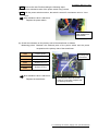
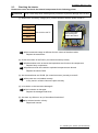
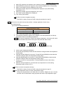
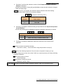
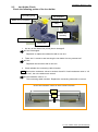
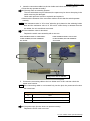
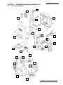
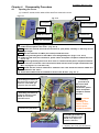
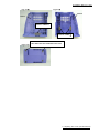
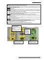
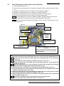
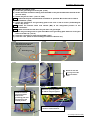
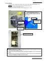
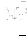
First Edition: March 31, 2007 [ For FX951-51 -up ] Service Manual TABLE OF CONTENTS Revision History Chapter 1 Inspection Flow Chart Chapter 2 Procedure and Method of Repair 2-1 Checking the Exterior 2-2 Checking the Power Supply Line 2-3 Checking the Interior 2-4 Voltage Application Check 2-5 Iron Holder Check 2-6 Inspection after Repair Chapter 3 Exploded Drawings and Parts List 3-1 Exploded Drawings 3-2 Station Parts List Chapter 4 Disassembly Procedure 4-1 Opening the Cover 4-2 P.W.B. (for Control/Connector) and Front Panel 4-3 Power Receptacle, Power Switch and Transformer 4-4 Jack 4-5 Iron Holder Chapter 5 Wiring Diagram Cautionary points during use Warnings, cautions and notes are placed at critical points in this manual to direct the operator’s attention to significant items. They are defined as follows: Please read the following sentences and understand them sufficiently before reading the main text. ▲WARNING: △CAUTION: NOTE: Failure to comply with a WARNING may result in serious injury or death. Failure to comply with a CAUTION may result in injury to the operator, or damage to the items involved. Indicates the items which operators are likely to make a mistake in and should pay attention to. Revised date: March 9, 2012 Revision History Revision Date Information Revised Description Approved by Created by March 31, 2007 - First edition Hirai Nishii March 9, 2012 3-2 Station Parts List Change the part number Nagase Nishii for Receptacle. B3076 → 699-031236 Revision History (FX-951/FH-200) First Edition: March 31, 2007 Chapter 1 Inspection Flow Chart Checking the Exterior Section 2-1 Checking the Power Supply Line Checking the Power Supply Line Section 2-2 (1)-(4) Section 2-2-(5)(6) Checking the Interior Section 2-3 Voltage Application Check Section 2-4 Iron Holder Check Section 2-5 Inspection after Repair Section 2-6 1 Inspection Flow Chart (FX-951/FH-200) First Edition: March 31, 2007 Chapter 2 Procedure and Method of Repair 2-1 Checking the Exterior Check the exterior for the following points. Power switch Power receptacle Operation buttons Rating seal Card insert slot Rubber feet Jack Receptacle Case R Case L (1) Are the case R and case L damaged? If the case R and case L are damaged: Replace each case. (2) Do the four operation buttons and card operate smoothly? If operations are not smooth: Installation of the P.W.B. (for control/connector) is faulty, or the P.W.B. itself is faulty. Install the P.W.B. again or replace the P.W.B. (for control/connector). (3) Does the receptacle allow smooth insertion and removal? If the receptacle does not allow smooth insertion or removal: Replace the P.W.B. (for control/connector). (4) Are the rubber feet of the case R and case L chipped or damaged? If the rubber feet of the case R and case L are chipped or damaged: Mount a new rubber feet or replace them. (5) Take out the fuse from the power receptacle and check that the fuse has not blown. Check the rating of the fuse with reference to the table on the right. If the fuse has blown: Replace the fuse. If the wrong fuse has been used: Replace the fuse. Voltage Fuse rating 100V-110V 250V-2A 220V-240V 250V-1A Hitch a tool into this slot and take out the fuse. 2-1 Checking the Exterior (FX-951/FH-200) First Edition: March 31, 2007 2-2 Checking the Power Supply Line Check the power supply line for the following points. (1) Has the sheath on the power cord been dropped or damaged? If the sheath on the power cord has been dropped or damaged: Replace the power cord, as it may break eventually. I: Measure across the ground line. (2) Measure the resistance values of the power cord at three points using a tester. (Photo on the right) NOTE The cord is normal if resistance values are “1Ω or less”. If a resistance value is abnormal: Replace the power cord. II, III: Touch the plug with the tester probe as shown in the photo and measure at two positions on the station side indicated by arrows. (3) During measurement in step (2) above, twist and bend the power cord at various angles (including the plug and the station connecting part). If abnormal resistance values are detected: The line is broken. Replace the power cord. (4) Turn on the power switch and measure the resistance value between power receptacle pins. NOTE Under normal conditions, the resistance values are as listed in the following table. (resistance values of the primary side of the transformer) 100V 5.6Ω to 6.8Ω 110V 6.0Ω to 7.4Ω 120V 6.5Ω~9.5Ω 220V 30.9Ω to 37.7Ω 230V 240V 30.4Ω to 37.2Ω Measure the value between these power receptacle pins. If the resistance value is different from the value in the table above: The power switch or the transformer is faulty. Proceed to steps (5) and (6). If the resistance value is within the above range: Proceed to section 2-3. 2-2 Checking the Power Supply Line (FX-951/FH-200) First Edition: March 31, 2007 NOTE Remove the case R before taking the following steps. (5) Measure a resistance value of the power switch using a tester. NOTE With the power switch turned on, the switch is normal if a resistance value is “1Ω or less”. If a resistance value is abnormal: Replace the power switch. Be sure to turn the power switch on for measurement. (6) Check the resistance on the primary side of the transformer as follows. Measuring points: Between the soldered parts of the power switch and the power receptacle on the primary side of the transformer. 100V 5.6Ω to 6.8Ω 110V 6.0Ω to 7.4Ω 120V 6.5Ω~9.5Ω 220V 30.9Ω to 37.7Ω 230V 240V Lead wires from the primary side of transformer 30.4Ω to 37.2Ω If a resistance value is abnormal: Replace the transformer. Measure the resistance between the pin (1) on the power switch side and the center pin on the power receptacle side (as shown by the arrow). 2-2 Checking the Power Supply Line (FX-951/FH-200) First Edition: March 31, 2007 2-3 Checking the Interior Remove the cover and check the internal components for the following points: CAUTION Wear a wrist strap when following these procedures to prevent damage to the P.W.B. (1) Measure the secondary voltage (ACV) of the transformer with the power turned on. 100V 110V 120 V 220V AC 24.3V to 29.7V Measure the voltage while touching the tester to this section. 230V 240V If the measured voltage is different from the values of the above table: Replace the transformer. (2) Check the surface of the P.W.B. (for control/connector) visually. If abnormalities such as cracks and explosions are found on the components: Replace faulty components. If portions around the cracked or exploded components are burned: Replace the whole P.W.B. (3) Are the transformer and P.W.B. (for control/connector) correctly mounted? If the parts are not installed correctly: It may result in a failure. Mount the parts correctly. (4) Is insulation on the lead wires damaged? If the insulation is damaged: Replace the damaged lead wires. (5) Are there any failures in any of the soldered lead wires? If a soldered section is faulty: Repair each section. 2-3 Checking the Interior (FX-951/FH-200) First Edition: March 31, 2007 2-4 Voltage Application Check Perform a voltage application check. NOTE Without attaching the iron, perform a check with the following procedures. (1) Check the soldering iron error. 1. Turn on the power switch. 2. The following indications appear on the display in the order presented, and the buzzer keeps beeping. Flashing → 8. 8. 8. C - E 3. Turn off the power switch. If no indication appears on the display: The P.W.B. is faulty. Check the P.W.B. using the procedure in step (7). When an indication appears on the display but it does not function properly: The P.W.B. is faulty. Check the P.W.B. using the procedure in step (7). NOTE Connect the iron (without the tip) and check according to the following procedures. (2) Check the sensor errors. 1. Turn on the power switch. 2. The following indications appear on the display in the order presented, and the buzzer keeps beeping. Setting temperature 8. 8. 8. → 3 5 0 Flashing → S - E (The example shows a setting at 350◦C.) 3. Turn off the power switch. If no indication appears on the display: The P.W.B. is faulty. Check the P.W.B. using the procedure in step (7). When an indication appears on the display but it does not function properly: The P.W.B. is faulty. Check the P.W.B. using the procedure in step (7). NOTE Connect the iron (without the tip) and check according to the following procedures. (3) Check the LCD. 1. Insert a card. 2. While holding down the four operation buttons, turn on the power switch. 3. After the version No. (ex. [001]) is displayed, the segment of the indicator [Left] will be lit sequentially. NOTE The figures to be displayed vary depending on the version of P.W.B. [Center] 2nd digit [Left] 3rd digit [UP] [*] [Right] 1st digit [DOWN] [#] 2-4 Voltage Application Check (FX-951/FH-200) First Edition: March 31, 2007 4. 5. 6. 7. After [UP] is pressed, the segment of the indicator [Center] will be lit sequentially. After [DOWN] is pressed, the segment of the indicator [Right] will be lit sequentially. After [*] is pressed, [4] will be displayed in the center. After [#] is pressed, figures around [769] will be displayed. (only when setting temperature (°C)) 8. After [#] is pressed, [6] will be displayed in the center. 9. If the card is pulled, [888] will be displayed. 10. Turn off the power switch. If the unit does not operate correctly: The P.W.B. is faulty. Check the P.W.B. using the procedure in step (7). NOTE Connect the iron (with the tip) and perform a voltage application check using the following steps: (4) Check the setting temperature. Setting temperature range In Centigrade 200°C to 450°C In Fahrenheit 400°F to 840°F 1. Turn on the power switch with a card detached. 2. The following indications appear on the display in the order presented, and the tip temperature rises to the setting temperature. NOTE When the tip temperature reaches the setting temperature, the buzzer will sound and the heater lamp at the lower right of the panel will start to flash. Setting temperature 8. 8. 8. → 3 5 0 Tip temperature → (The example shows a setting at 350°C.) 3 5 0. Heater lamp 3. Insert a card. Indicator [Left] flashes. 4. Press [UP] and [DOWN] to check that the indication changes within the temperature setting range. 5. Indicator [Center] flashes if you press [*]. Press [UP] and [DOWN] to check that the indication changes within the temperature setting range. 6. Indicator [Right] flashes if you press [*]. Press [UP] and [DOWN] to check that the indication changes within the temperature setting range. 7. Press [*] to return to usual operations. The tip temperature rises to the setting temperature. 8. Measure the tip temperature. (Check that the tip temperature is at the setting temperature plus or minus 15°C.) If the unit does not operate correctly: The P.W.B. is faulty. Check the P.W.B. using the procedure in step (7). If a tip temperature does not reach a temperature range: The tip has degenerated or an offset value is incorrect. Replace the tip or correct an offset value as described in step (5) below and check a tip temperature again. 2-4 Voltage Application Check (FX-951/FH-200) First Edition: March 31, 2007 (5) Check the offset value. Input range for the offset value In Centigrade -50°C to + 50°C In Fahrenheit -90°F to + 90°F 1. Hold down [#] for one second or longer to make the indicator [Left] flash, indicating “0” or “-”. 2. Press [UP] and [DOWN] to check that the indication changes alternately between [0] and [-]. 3. Indicator [Center] flashes by pressing [*]. Press [UP] and [DOWN] to check that the indication changes within the input range. 4. Indicator [Right] flashes by pressing [*]. Press [UP] and [DOWN] to check that the indication changes within the input range. 5. Press [*] to return to usual operations. NOTE If an input range of offset values is exceeded, the operation returns to the beginning. If the unit does not operate correctly: The P.W.B. is faulty. Check the P.W.B. using the procedure in step (7). (6) Check the parameters. 1. Turn off the power switch before inserting the card. 2. If turning on the power switch while pressing the [UP] and [DOWN] at the same time, the mode will change to the temperature scale setting. • Check that pressing the [UP] and [DOWN] changes the indication alternately as follows: 1 C 1 F Temperature scale setting C Centigrade (°C) F Fahrenheit (°F) 3. Pressing [*] accepts the indicated setting and proceeds to the “Power save setting”. • Check that pressing [UP] and [DOWN] changes the indication within the input range. 2 0 2 1 2 3 0 * The above example shows the case when it is set to 1 min. Power save setting 0 OFF 1 to 29 Indicates “SLP” after the set time has elapsed. 30 Indicates “---” after 30 minutes. NOTE Check the power-save operation according to the procedure in Section 2-5: "Iron Holder Check “ 2-4 Voltage Application Check (FX-951/FH-200) First Edition: March 31, 2007 4. Pressing [*] confirms the indication, and the “Low Temperature Alarm Tolerance Setting” is indicated. • Indicator [Left] flashes. Press [UP] and [DOWN] to check that the indication changes within the input range. NOTE Every time [*] is pressed, the indication will be determined and the flashing indicator will be shifted from [Center] to [Right]. 1 5 0 (Example of indicating 150°C) Temperature Input range of low temperature indication alarm setting °C 30 to 150 °F 50 to 300 5. Pressing [*] accepts the indicated setting and proceeds to the “Supervisor/operator Control Setting”. • Check that pressing [UP] or [DOWN] changes the indication alternately as follows: 4 0 4 1 Supervisor/operator control setting”. 0 Card is required for offset value entry 1 Offset value entry is allowed without card 6. Pressing [*] finishes the parameter setting and returns the unit to the normal operation. If the unit does not operate correctly: The P.W.B. is faulty. Check the P.W.B. using the procedure in step (7). NOTE Perform the following inspection if the unit does not operate in steps (1) to (6). (7) Visually inspect the reverse side of the P.W.B. (for control/connector) for faulty soldering or pattern exfoliation. If a faulty portion is found: Correct soldering. If a pattern coming off is found: Replace the whole P.W.B. CAUTION If a fault is not found visually, replace the whole P.W.B. (for control/connector). 2-4 Voltage Application Check (FX-951/FH-200) First Edition: March 31, 2007 2-5 Iron Holder Check Check the following points of the iron holder. Tip holding spring Iron receptacle Holder for iron receptacle Stay Switch case assembly Iron holder base Cleaner base 1. Are any of the rubber feet (4 feet) lost or damaged? If lost or damaged: Replenish or replace the rubber foot with a new one. 2. There are 11 screws in total securing the iron holder. Are any screws lost? If lost: Replenish the lost screw with a new one. 3. Check whether the connecting cable is broken. NOTE Measure the resistance values in sections A and B. If each resistance value is “1Ω or less”, the unit conditions are normal. If the resistance value is ∞: The connecting cable is broken. Replace the connecting cable with a new one. Check the resistance values in the 2 sections A and B. A B 2-5 Iron holder check (FX-951/FH-200) First Edition: March 31, 2007 4. Insert the connection cable into the iron holder and check the following points: • Does the stay operate smoothly? If the stay does not smoothly operate: The iron holder base may be deformed, the spacer may be lost or the spring in the switch case may be damaged. Check each point and correct or replenish and replace it. • Measure the resistance of the connection cable to check that the switch operates normally. NOTE If the resistance value is “1Ω or less” when the tip is placed on the soldering holder base and the resistance value is “4.7kΩ ±10%” when the tip is released from the iron holder, the unit conditions are normal. If the resistance value is abnormal: Replace the switch case assembly with a new one. If the resistance value is “1Ω or less” in this condition, the unit conditions are normal. If the resistance value is “4.7kΩ ±10%” in this condition, the unit conditions are normal. Apply tester here to measure. 5. Connect the connecting cable to the iron holder and FX-951 and then check the power save function. NOTE If the connecting cable is not inserted fully into the jack, the power-save function will not activate. Power save setting 0 OFF 1 to 29 Indicates “SLP” after the set time has elapsed. 30 Indicates “---” after 30 minutes. If the power-save function does not operate normally: Replace the P.W.B. with a new one. 2-5 Iron holder check (FX-951/FH-200) First Edition: March 31, 2007 2-6 Inspection after Repair Perform the inspection after repair. <Preparations> W-I tester / DMM (Tester) / Power meter (or ammeter) / Thermo-couple thermometer (HAKKO192) (1) Voltage application test Resistance between power receptacle ground terminal and receptacle pin 2 (for measurement point, refer to the photo) is 1Ω or lower. Resistance between power receptacle ground terminal and IRON 2 receptacle pin 2 is 1Ω or lower. Power receptacle grounding terminal Pin 2: Center at bottom (2) Insulation test and withstanding voltage test [Insulation test] Apply 500VDC and check that the value is 25MΩ or higher. [Withstanding voltage test] Apply 1250VAC (1mA) to check that it can resist for 1 second or longer. NOTE Perform the following inspections with a proper tip. (3) Check the power consumption. Power consumption must be 75W ±10%. (4) Measure the tip-to-ground potential and the tip to ground resistance. The tip-to-ground potential must be 1mV or lower. The tip to ground resistance must be 1.0Ω or less. (5) Check the temperature. The tip temperature must be at the setting temperature ±15°C. CAUTION If an accessory iron is provided, return it to a customer with lead-free solder put on the tip. (To prevent oxidation) 2-6 Inspection after Repair (FX-951/FH-200) First Edition: March 31, 2007 Chapter 3 3-1 Exploded Drawings and Parts List Exploded Drawings G K H E L F 3 C M D B A 1 2 I J O P T N U R Q S 3-1 Exploded Drawings (FX-951/FH-200) Revised date: March 9, 2012 3-2 Station Parts List Category A Sales Front panel B2973 B Sales Button set B2982 C Sales P.W.B. for control D Sales Part name Case L E Sales Case R F Sales Transformer G Sales Power switch H Sales Fuse Specifications Product No. for each voltage No. 100V 110V For control and connector Power cord With rubber feet/cushion rubber B B2979 B2983 B2836 B2984 B3067 B2852 B2403(250V-2A)B2387 - B2987(250V-1A) - - B2419 Vinyl 3-conductor CH plug - - - Without vinyl 3-conductor plug - - - Molded BS plug - - - B2436 Australian plug - - - - - - - - B2422 B2424 - - B2424 - - - - Sales Card B2972 K Sales Power receptacle B2666 L Sales Grounding plate B2227 M Sales Connecting cable B3253 N Sales Iron receptacle O Sales Tip fixing spring B2791 P Sales Holder for iron receptacle B3248 Q Sales Iron holder base R Sales Cleaning sponge S Sales Cleaner base T Sales Stay B3250 U Sales Switch case assembly B3252 With rubber feet - - B2425 J With screws - B2421 European plug CE Rubber feet B2985 * The transformer 230V for Australian plug is B3067. European plug Sales 240V B2978 (Refer to Photo 4-1-5 to 4-1-7) Molded BS plug CE * 230V B3255 (Refer to Photo 4-1-5 to 4-1-7) Vinyl 2-pole grounding Sales 220V B3256 With rubber feet/cushion rubber A Rubber 2-pole grounding I 120V - B2426 B3001 B3251 A1536 With rubber feet Two feet for FX-951 station (Refer to Photo 4-1-5 to 4-1-7) B3249 B2016 3-2 Station Parts List (FX-951/FH-200) Revised date: March 9, 2012 No. Category Part name 1 Repair Holder 2 Repair Only receptacle Specifications Product No. for each voltage 100V 110V 120V 220V 230V 240V B3073 Please let us know the following part number when ordering. 699-031236 PJ-35N With nut 3 Repair Jack * Repair Cushion rubber A * Repair Cushion rubber B B3329 For case L (Refer to Photo 4-1-5 ) For case R (Refer to Photo 4-1-6 ) B3086 B3087 3-2 Station Parts List (FX-951/FH-200) First Edition: March 31, 2007 Chapter 4 4-1 Disassembly Procedure Opening the Cover (1) Loosen 5 screws on the sides of the case R to remove the cover. Fig. 4-1-1 Fig. 4-1-2 Front panel Power switch Power receptacle Case R P.W.B. (for control) Transformer P.W.B. (for connector) Case L ●Assembly procedures (opening) (1) Install the front panel in the case L. (Fig. 4-1-3) NOTE Install the red lead wire and the lead wire for jack (white) carefully so that they do not get caught. NOTE Run the lead wire of P.W.B. (for control) outside the boss. (2) Install the grounding wire for the P.W.B. in the designated place. (Figs. 4-1-3, 4-1-4) (3) Install the lead wires for transformer, power switch and power receptacle outside the boss. (Fig. 4-1-3) NOTE Run the grounding wire not to let it come in contact with the power receptacle terminal. (4) Cover the case L with the case R and secure them with 5 screws (P tight round head screw M3 × 16) (Figs 4-1-3, 4-1-5 and 4-1-6) NOTE Check that the cushion rubber B is installed in the case R and the cushion rubber A is installed in the case L. (5) Check that 2 rubber feet are installed in each of case R and L. (Fig. 4-1- 7) Fig. 4-1-3 Assembly procedure (1) Be careful not to let the red lead wire of the P.W.B. get caught on the front panel. Assembly procedure (1) Install the lead wire of the P.W.B. (for connector) outside the boss. Lead wire for jack (white) Assembly procedure (3) Run all the lead wires for the transformer, power switch and power receptacle outside the boss. NOTE Be careful not to let the grounding wire come in contact with the power receptacle terminal. 4-1-4 Assembly procedure (2) Install the lead wire of the P.W.B. in the depressed section in the case. 4-1 Opening the Cover (FX-951/FH-200) First Edition: March 31, 2007 Fig. 4-1- 5 Fig 4-1- 6 Case R Case L Cushion rubber A Cushion rubber B Fig.-4-1- 7 Rubber feet Two rubber feet are installed for each case. 4-1 Opening the Cover (FX-951/FH-200) First Edition: March 31, 2007 4-2 P.W.B. (for Control/Connector) and Front Panel (1) Follow the procedures 4-1. (2) Disconnect the connector for jack from the P.W.B. (4-2-1) (3) Desolder 2 soldered sections at the secondary side of the transformer. (Fig. 4-2-1) (4) Disconnect the grounding wire for P.W.B from the grounding plate. (Fig. 4-2-1) Note The grounding wire for P.W.B. is attached together with the grounding wire for jack. Fig. 4-2-1 Front panel Secondary side of transformer Connector for jack Grounding plate The grounding wires for P.W.B. and jack are attached together. (5) Remove 4 screws and then disconnect the P.W.B. for control from the front panel. (Fig. 4-2-2) (6) Remove 4 screws and then disconnect the P.W.B. for connector and holder from the front panel. (Fig. 4-2-3) (7) Remove 2 screws and disconnect the buttons R and L. (Fig. 4-2-3) Fig. 4-2-2 Fig. 4-2-3 Two screws securing the buttons R and L Four screws securing the P.W.B. for control Four screws securing the P.W.B. for connector Reference photo If the 4 screws are removed, the holder in the photo at left will be removed. 4-2 P.W.B. (for Control/Connector) and Front Panel (FX-951/FH-200) First Edition: March 31, 2007 ●Assembly procedures (P.W.B. (for control/connector)) (1) Attach the buttons R and L onto the front panel with 2 screws (P tight round head screw M2.6 x 6). (Figs. 4-2-3 to 4-2-5) NOTE Attach the buttons R and L properly, so as to correlate with the indications on the front panel. NOTE To prevent buttons from being cracked, be careful not to tighten screws excessively. (2) Mount the P.W.B. (for connector) onto the front panel with the holder and 4 screws (P tight round head screw M2.6 x 8). (Figs. 4-2-3 to 4-2-5) (3) Mount the P.W.B. (for control) onto the front panel with 4 screws (P tight round head screw M2.6 x 8). (Figs. 4-2-2, 4-2-5 and 4-2-6) NOTE Align the holes of the P.W.B. with 2 depressed sections of the front panel. (4) Run the lead wire of the connector section under the P.W.B. to insert and pull the card smoothly. (Fig. 4-2-6) (5) Mount the grounding wire of the P.W.B. onto the grounding plate with 1 screw (round head screw M4 x 6). (Fig. 4-2-1) NOTE Run the grounding wire as close as possible to parallel with the edge of the grounding plate and attach it together with the grounding wire for jack. (6) Solder the lead wire of the P.W.B. to the secondary side of the transformer. (7) Plug the connector for jack into the P.W.B. (4-2-1) (8) Close the case. (Refer to the assembly procedures in Section 4-1.) Fig. 4-2-4 When attaching buttons: • Correlate with the indications on the front panel • Be careful not to tighten screws excessively. Appearance where the holder was installed and secured with screws Fig. 4-2-5 Fig. 4-2-6 Press-fit the depressed section of the front panel into the hole of the P.W.B. Run the lead wire under the P.W.B. to insert and pull the card smoothly. 4-2 P.W.B. (for Control/Connector) and Front Panel (FX-951/FH-200) First Edition: March 31, 2007 4-3 Power Receptacle, Power Switch and Transformer (1) Follow the procedures in 4-1. (2) Disconnect the grounding wire of the power receptacle from the grounding plate. (Photo 14) (3) Desolder 3 soldered sections of the lead wire of the power receptacle. (4) Desolder 2 soldered sections of the lead wire of the power switch. (5) Desolder 2 soldered sections of the secondary lead wire of the transformer. (6) Remove the grounding wire of the P.W.B. from the grounding plate. NOTE The grounding wire for P.W.B. is attached together with the grounding wire for jack. (7) Remove 4 screws securing the transformer, grounding plate and chassis. NOTE The external tooth lock washer is installed in only one section. Be careful not to lose it. (Photo 14) Power switch Fig. 4-3-1 Case L Power receptacle Grounding plate Transformer Grounding wire for power receptacle Grounding wires for P.W.B. and jack Secondary side of the transformer Caution regarding external tooth lock washer The external tooth lock washer is installed on this screw between the grounding plate and transformer. ●Assembly procedures (Power receptacle, power switch and transformer) (1) Mount the transformer and grounding plate onto case L with 4 screws (TP Bind B1 M3.5 x 45). NOTE Install the external tooth lock washer (M4) in the designated place of the transformer. (Fig. 4-3-1) NOTE Check that the cushion rubber A is installed in the case L. (Fig. 4-1-5) (2) Mount the grounding wire of the P.W.B. onto the grounding plate with 1 screw (round head screw M4 x 6). (Fig. 4-3-1) NOTE Run the grounding wire as close as possible to parallel with the edge of the grounding plate and attach it together with the grounding wire for jack. (3) Solder the lead wire of the P.W.B. to the secondary side of the transformer. (Fig. 4-3-1) (4) Solder the black lead wire of the transformer and the black lead wire leading from the power receptacle to the power switch. (Fig. 4-3-2) (5) Solder the white lead wire of the transformer, the black lead wire leading from the power switch and grounding wire to the power receptacle. (Fig. 4-3-3) (6) Mount the grounding wire of the power receptacle to the grounding plate with 1 screw (round head screw M4 x 6). (Fig. 4-3-1) NOTE Mount the grounding wire to be aligned parallel with the grounding plate. (7) Close the case. (Refer to Assembly Procedures in Section 4-1.) 4-3 Power Receptacle, Power Switch and Transformer (FX-951/FH-200) First Edition: March 31, 2007 Fig. 4-3-2 Fig. 4-3-3 Assembly procedure (5) Solder the white lead wire of the transformer. Assembly procedure (5) Solder the grounding wire. Assembly procedure (4) Solder the black lead wire of the transformer. Assembly procedures (4) and (5) Solder the black lead wire to the terminals of the power switch and power receptacle. 4-3 Power Receptacle, Power Switch and Transformer (FX-951/FH-200) First Edition: March 31, 2007 4-4 Jack (1) Perform the procedures in Section 4-1. (Open the case). (2) Disconnect the connector for jack from the P.W.B. (4-4-1) (3) Disconnect the grounding wire for jack from the grounding plate. (4-4-1) NOTE This grounding wire is attached together with the grounding wire for P.W.B. (4) Remove the 4 screws securing the transformer, grounding plate and chassis. (4-4-1) NOTE The external tooth lock washer is installed in only one place. Be careful not to lose it. (5) Remove the nut outside the case to remove the jack from the case. (4-4-2, 4-4-7, 4-4-8) 4-4-1 4-4-2 Connector in disassembly procedure (2) The connector for jack is inserted. Transformer Grounding plate Nut in disassembly procedure (5) Grounding wire in disassembly procedure (3) Secured together with the grounding wire for P.W.B. (6) Desolder the 3 soldered sections of the jack. 4-4-3 Grounding wire for jack White lead wire to be connected to the P.W.B. 3 soldered sections 4-4 Jack (FX-951/FH-200) First Edition: March 31, 2007 ●Assembly procedures (Jack) (1) Solder the grounding wire to the jack. (4-4-4) (2) Solder the white lead wires leading from the P.W.B. to the jack and bend the terminal at 90º. (4-4-4 to 4-4-6) (3) Attach the jack to Case L. (4-4-7 to 4-4-8) NOTE Note that the jack nut attachment orientation is specified. Be careful not to install it backwards. (4-4-8) (4) Attach the transformer and grounding plate to the case L with 4 screws (TP Binding B1 M3.5 x 45). (4-4-9) NOTE Install the external tooth lock washer (M4) at the designated position of the transformer. NOTE Make sure that the lead wires for jack does not get caught. (5) Attach the grounding wires for jack and P.W.B. to the grounding plate with one screw (pan head screw M4 x 6). (4-4-10) (6) Insert the connector for jack into the P.W.B. (4-4-1) (7) Close the case. (Refer to the assembly procedures in Section 4-1.) 4-4-4 4-4-5 Two white lead wires to be connected to the P.W.B. (They do not have polarities.) 4-4-6 90° Grounding wire 90° 4-4-7 4-4-8 Attach the nut with the non-groove side facing toward the case. 4-4-9 4-4-10 Attach the grounding wires for P.W.B. and jack together. Install the external tooth lock washer between the grounding plate and transformer at the marked position. Run the lead wires for jack as shown in 4-4-9 and 4-4-10. 4-4 Jack (FX-951/FH-200) First Edition: March 31, 2007 4-5 Iron Holder (1) Remove the 2 screws of the switch case to remove the switch case assembly. (4-5-1) NOTE Be careful not to lose the spring in the switch case. (4-5-3) (2) Remove 1 screw of the stopper. (4-5-1) (3) Remove 2 screws of the stay to remove the stay. (4-5-1, 4-5-2) 4-5-1 Screw in disassembly procedure (3) The spacer is installed between the screw and iron holder base. (There is another spacer on the opposite side.) Stay 4-5-2 Spacer Switch case Pan head screw with spring washer P2 M3 × 8 Screws in disassembly (1) Screw in disassembly (2) 4-5-3 Spring for switch case ●Assembly procedures (Iron holder) (1) Attach the stay to the iron holder base with the 2 spacers and 2 screws (Pan head screw with spring washer P2 M3 × 8). (4-5-1) (2) Attach one screw (pan head screw with spring washer P2 M3×8) to the iron holder base. (4-5-1) (3) Install the spring in the switch case and attach the switch case to the iron holder base with the 2 screws (Tapping screws M3 × 12). (4-5-1, 4-5-3) 4-5 Iron Holder (FX-951/FH-200) First Edition: March 31, 2007 Chapter 5 Wiring Diagram Grounding plate Power receptacle Power switch White Control P.W.B Jack Black Transformer Power receptacle P.W.B Red Red 5 Wiring Diagram (FX-951/FH-200)


![Instruction Manual - [HAKKO] Document Portal](http://vs1.manualzilla.com/store/data/005882531_1-c17999a04ed3b96f12c2eb288800f74b-150x150.png)