1
FOREWORD
This Supplementary Service Manual has been prepared to introduce new service and data for the
XJR1300 (P) 2002. For complete service information procedures it is necessary to use this Supplementary Service Manual together with the following manual.
XJR1300 (L) ’99 SERVICE MANUAL: 5EA3-AE1
EAS00000
XJR1300 (P) 2002
SUPPLEMENTARY
SERVICE MANUAL
2001 by Yamaha Motor Co., Ltd.
1st Edition, August 2001
All rights reserved.
Any reprinting or unauthorized use
without the written permission of
Yamaha Motor Co., Ltd.
is expressly prohibited.
EAS00003
NOTICE
This manual was produced by the Yamaha Motor Company, Ltd. primarily for use by Yamaha dealers
and their qualified mechanics. It is not possible to include all the knowledge of a mechanic in one manual. Therefore, anyone who uses this book to perform maintenance and repairs on Yamaha vehicles
should have a basic understanding of mechanics and the techniques to repair these types of vehicles.
Repair and maintenance work attempted by anyone without this knowledge is likely to render the vehicle unsafe and unfit for use.
This model has been designed and manufactured to perform within certain specifications in regard to
performance and emissions. Proper service with the correct tools in necessary to ensure that the vehicle will operate as designed. If there is any question about a service procedure, it is imperative that
you contact a Yamaha dealer for any service information changes that apply to this model. This policy
is intended to provide the customer with the most satisfaction from his vehicle and to conform with federal environmental quality objectives.
Yamaha Motor Company, Ltd. is continually striving to improve all its models. Modifications and significant changes in specifications or procedures will be forwarded to all authorized Yamaha dealers and
will appear in future editions of this manual where applicable.
NOTE:
! This Service Manual contains information regarding periodic maintenance to the emission control
system. Please read this material carefully.
! Designs and specifications are subject to change without notice.
EAS00004
IMPORTANT INFORMATION
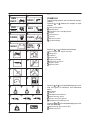
Particularly important information is distinguished in this manual by the following.
The Safety Alert Symbol means ATTENTION! BECOME ALERT! YOUR
SAFETY IS INVOLVED!
Failure to follow WARNING instructions could result in severe injury or death to
the motorcycle operator, a bystander or a person checking or repairing the motorcycle.
CAUTION:
NOTE:
A CAUTION indicates special precautions that must be taken to avoid damage
to the motorcycle.
A NOTE provides key information to make procedures easier or clearer.
EAS00007
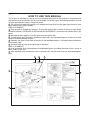
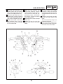
HOW TO USE THIS MANUAL
This manual is intended as a handy, easy-to-read reference book for the mechanic. Comprehensive
explanations of all installation, removal, disassembly, assembly, repair and check procedures are laid
out with the individual steps in sequential order.
1 The manual is divided into chapters. An abbreviation and symbol in the upper right corner of each
page indicate the current chapter.
Refer to “SYMBOLS”.
2 Each chapter is divided into sections. The current section title is shown at the top of each page,
except in Chapter 3 (“PERIODIC CHECKS AND ADJUSTMENTS”), where the sub-section title(-s) appears.
3 Sub-section titles appear in smaller print than the section title.
4 To help identify parts and clarify procedure steps, there are exploded diagrams at the start of each
removal and disassembly section.
5 Numbers are given in the order of the jobs in the exploded diagram. A circled number indicates a
disassembly step.
6 Symbols indicate parts to be lubricated or replaced.
Refer to “SYMBOLS”.
7 A job instruction chart accompanies the exploded diagram, providing the order of jobs, names of
parts, notes in jobs, etc.
8 Jobs requiring more information (such as special tools and technical data) are described sequentially.
2
1
4
3
5
8
6
7
EAS00009
1
2
GEN
INFO
SPEC
3
4
CHK
ADJ
ENG
5
6
CARB
CHAS
7
8
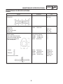
SYMBOLS
The following symbols are not relevant to every
vehicle.
Symbols 1 to 8 indicate the subject of each
chapter.
1 General information
2 Specifications
3 Periodic checks and adjustments
4 Engine
5 Carburetor(-s)
6 Chassis
7 Electrical system
8 Troubleshooting
TRBL
SHTG
ELEC
10
Symbols 9 to 16 indicate the following.
9 Serviceable with engine mounted
11
12
10
11
12
13
14
15
16
13
14
15
16
9
17
20
23
18
19
21
22
24
Filling fluid
Lubricant
Special tool
Tightening torque
Wear limit, clearance
Engine speed
Electrical data
Symbols 17 to 22 in the exploded diagrams indicate the types of lubricants and lubrication
points.
17
18
19
20
21
22
Engine oil
Gear oil
Molybdenum disulfide oil
Wheel bearing grease
Lithium soap base grease
Molybdenum disulfide grease
Symbols 23 to 24 in the exploded diagrams indicate the following:
23 Apply locking agent (LOCTITE)
24 Replace the part
CONTENTS
SPECIFICATIONS
GENERAL SPECIFICATIONS . . . . . . . . . . . . . . . . . . . . . . . . . . . . . . . .
MAINTENANCE SPECIFICATIONS . . . . . . . . . . . . . . . . . . . . . . . . . . .
ENGINE . . . . . . . . . . . . . . . . . . . . . . . . . . . . . . . . . . . . . . . . . . . . . . . .
CHASSIS . . . . . . . . . . . . . . . . . . . . . . . . . . . . . . . . . . . . . . . . . . . . . . .
ELECTRICAL . . . . . . . . . . . . . . . . . . . . . . . . . . . . . . . . . . . . . . . . . . .
CABLE ROUTING . . . . . . . . . . . . . . . . . . . . . . . . . . . . . . . . . . . . . . . . . .
1
3
3
6
8
9
PERIODIC INSPECTION AND ADJUSTMENT
INTRODUCTION . . . . . . . . . . . . . . . . . . . . . . . . . . . . . . . . . . . . . . . . . . .
PERIODIC MAINTENANCE/LUBRICATION INTERVALS . . . . . . .
ENGINE . . . . . . . . . . . . . . . . . . . . . . . . . . . . . . . . . . . . . . . . . . . . . . . . . . .
ADJUSTING THE CLUTCH LEVER . . . . . . . . . . . . . . . . . . . . . . . .
CHASSIS . . . . . . . . . . . . . . . . . . . . . . . . . . . . . . . . . . . . . . . . . . . . . . . . . .
ADJUSTING THE FRONT BRAKE . . . . . . . . . . . . . . . . . . . . . . . . .
20
20
22
22
23
23
CARBURETORS
AIR INDUCTION SYSTEM . . . . . . . . . . . . . . . . . . . . . . . . . . . . . . . . . . .
AIR INJECTION . . . . . . . . . . . . . . . . . . . . . . . . . . . . . . . . . . . . . . . . .
AIR CUTOFF VALVE . . . . . . . . . . . . . . . . . . . . . . . . . . . . . . . . . . . . .
AIR INDUCTION SYSTEM DIAGRAMS . . . . . . . . . . . . . . . . . . . . .
CHECKING THE AIR INDUCTION SYSTEM . . . . . . . . . . . . . . . .
24
24
24
25
26
CHASSIS
FRONT AND REAR BRAKES . . . . . . . . . . . . . . . . . . . . . . . . . . . . . . . .
FRONT BRAKE MASTER CYLINDER . . . . . . . . . . . . . . . . . . . . . .
ASSEMBLING AND INSTALLING THE
FRONT BRAKE MASTER CYLINDER . . . . . . . . . . . . . . . . . .
REAR BRAKE CALIPER . . . . . . . . . . . . . . . . . . . . . . . . . . . . . . . . . .
27
27
28
30
ELECTRICAL
CARBURETOR HEATING SYSTEM . . . . . . . . . . . . . . . . . . . . . . . . . . 32
TROUBLESHOOTING . . . . . . . . . . . . . . . . . . . . . . . . . . . . . . . . . . . 33
XJR1300 2002 WIRING DIAGRAM (for EUR)
XJR1300P 2002 WIRING DIAGRAM (for AUS)
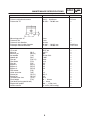
GENERAL SPECIFICATIONS
SPEC
SPECIFICATIONS
GENERAL SPECIFICATIONS
Model
XJR1300 (P)
Model code:
5EAT/5EAW (EUR)
5EAU/5EAX (for D)
5EAV/5EAY (for AUS)
Dimensions:
Overall length
Overall width
Overall height
Seat height
Wheelbase
Minimum ground clearance
Minimum turning radius
2,175 mm
775 mm
1,115 mm
790 mm
1,510 mm
120 mm
2,800 mm
Basic weight:
With oil and full fuel tank
247 kg
Carburetor:
Type/quantity
Manufacturer
BSR37/4
MIKUNI
Transmission:
Primary reduction system
Primary reduction ratio
Secondary reduction system
Secondary reduction ratio
Transmission type
Operation
Gear ratio 1st
2nd
3rd
4th
5th
Spur gear
98/56 (1.750)
Chain drive
39/18 (2.167)
Constant mesh 5-speed
Left foot operation
40/14 (2.857)
36/18 (2.000)
33/21 (1.571)
31/24 (1.292)
29/26 (1.115)
1
GENERAL SPECIFICATIONS
Model
Tire:
Type
Size
XJR1300 (P)
Tubeless
120/70ZR17 (58W)/
120/70ZR17 M/C (58W)
180/55ZR17 (73W)/
180/55ZR17 M/C (73W)
MICHELIN/DUNLOP
MICHELIN/DUNLOP
MACADAM90X E/D220F ST M
MACADAM90X E/D220 ST M
front
rear
Manufacturer
Type
SPEC
front
rear
front
rear
Tire pressure (cold tire):
Maximum load-except motorcycle
Loading condition A *
front
rear
Loading condition B *
front
rear
High-speed riding
front
rear
203 kg
0 ! 90 kg
250 kPa (2.5 kg/cm2, 2.5 bar)
250 kPa (2.5 kg/cm2, 2.5 bar)
90 ! 203 kg
250 kPa (2.5 kg/cm2, 2.5 bar)
290 kPa (2.9 kg/cm2, 2.9 bar)
250 kPa (2.5 kg/cm2, 2.5 bar)
290 kPa (2.9 kg/cm2, 2.9 bar)
*Load is the total weight of cargo, rider, passenger, and accessories.
2
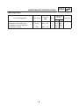
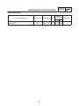
MAINTENANCE SPECIFICATIONS
SPEC
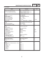
MAINTENANCE SPECIFICATIONS
ENGINE
Model
Standard
Limit
Cylinder head:
Warp limit
!!!
0.2 mm
Cylinder:
Bore size
Taper limit
Out of round limit
Wear limit
79.00 ! 79.01 mm
!!!
!!!
!!!
!!!
0.05 mm
0.1 mm
79.1 mm
Chain drive (Center)
25.000 ! 25.021 mm
24.967 ! 24.980 mm
0.020 ! 0.054 mm
!!!
!!!
!!!
!!!
35.95 ! 36.05 mm
28.058 ! 28.158 mm
35.95 ! 36.05 mm
28.045 ! 28.145 mm
!!!
35.85 mm
27.958 mm
35.85 mm
27.945 mm
0.03 mm
Camshaft:
Drive method
Cam cap inside diameter
Camshaft outside diameter
Shaft-to-cap clearance
Cam dimensions
Intake
“A”
“B”
Exhaust “A”
“B”
Camshaft runout limit
3
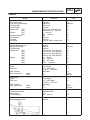
MAINTENANCE SPECIFICATIONS
Model
Piston:
Piston to cylinder clearance
Piston size “D”
Measuring point “H”
Piston off-set
Piston off-set direction
Piston pin bore inside diameter
Piston pin outside diameter
Carburetor:
I.D. mark
Main jet
(M.J)
Main air jet
(M.A.J)
Jet needle
(J.N)
Needle jet
(N.J)
Pilot jet
(P.A.J.1)
Pilot outlet
(P.O)
Pilot jet
(P.J)
Bypass 1
(B.P.1)
Bypass 2
(B.P.2)
Bypass 3
(B.P.3)
Pilot screw
(P.S)
Valve seat size
(V.S)
Starter jet
(G.S.1)
Starter jet
(G.S.2)
Throttle valve size
(Th.V)
Float height
(F.H)
Fuel level (using special tool)
Engine idle speed
Intake vacuum
SPEC
Standard
Limit
0.015 ! 0.040 mm
78.970 ! 78.985 mm
0.15 mm
!!!
5 mm
1 mm
IN side
18.004 ! 18.015 mm
17.991 ! 18.000 mm
!!!
!!!
!!!
18.045 mm
17.971 mm
5EAT 30
#107.5
#80
5D118-53-3
P-0M
#140
ø1.0
#15
0.9
0.9
0.8
2
2.3
#52.5
0.8
#115
33 ! 34 mm
3 ! 4 mm
950 ! 1,150 r/min
31.3 kPa (235 mmHg)
!!!
!!!
!!!
!!!
!!!
!!!
!!!
!!!
!!!
!!!
!!!
!!!
!!!
!!!
!!!
!!!
!!!
!!!
!!!
!!!
4
MAINTENANCE SPECIFICATIONS
SPEC
Tightening torques
Part to be tightened
g
Carburetor joint and carburetor
Carburetor and air filter joint
Air induction system pipe joint
Air induction system
Part name
Band
Clamp
–
Bolt
5
Thread
size
Q’tyy
M4 " 0.7
M4 " 0.7
–
M6 " 1.0
4
4
4
2
Tightening
torque
Nm
m!kg
2.7
2.7
3.7
10
0.27
0.27
0.37
1.0
Remarks
MAINTENANCE SPECIFICATIONS
SPEC
CHASSIS
Model
Standard
Limit
Front suspension:
Front fork travel
Fork spring free length
Fitting length
Collar length
Spring rate
(K1)
(K2)
Stroke
(K1)
(K2)
Optional spring
Oil capacity
Oil level
Oil grade
130 mm
308.3 mm
287.3 mm
245 mm
6.4 N/mm (0.65 kg/mm)
10.8 N/mm (1.1 kg/mm)
0 ! 85 mm
85 ! 130 mm
No
568 cm3
118 mm
Fork oil 10W or equivalent
!!!
300 mm
!!!
!!!
!!!
!!!
!!!
!!!
!!!
!!!
!!!
!!!
Rear suspension:
Shock absorber travel
Spring free length
Fitting length
Spring rate
(K1)
(K2)
(K3)
(K4)
Stroke
(K1)
(K2)
(K3)
(K4)
93 mm
230 mm
209 mm
19.4 N/mm (1.98 kg/mm)
21.4 N/mm (2.18 kg/mm)
26.3 N/mm (2.68 kg/mm)
28.2 N/mm (2.88 kg/mm)
0 ! 13 mm
13 ! 50 mm
50 ! 67.5 mm
67.5 ! 93.0 mm
!!!
225 mm
!!!
!!!
!!!
!!!
!!!
!!!
!!!
!!!
!!!
!!!
!!!
radial
lateral
Cast wheel
17 " MT3.50 or
17 M/C " MT3.50
Aluminum
!!!
!!!
!!!
!!!
radial
lateral
Cast wheel
17 " MT3.50 or
17 M/C " MT3.50
Aluminum
!!!
!!!
Drive chain:
Type/manufacturer
No. of links
Chain free play
50VA8/DAIDO
112
20 ! 30 mm
!!!
!!!
!!!
Brake lever & brake pedal:
Brake pedal position
40 mm
!!!
Front wheel:
Type
Rim size
Rim material
Rim runout limit
Rear wheel:
Type
Rim size
Rim material
Rim runout limit
6
!!!
1 mm
0.5 mm
!!!
1 mm
0.5 mm
MAINTENANCE SPECIFICATIONS
SPEC
Tightening torques
Part to be tightened
g
Part name
Thread size Q’ty
y
Tightening
torque
Nm m!kg
Throttle cable and carburetor
Ignition coil
Nut
Nut
M6 " 1.0
M6 " 1.0
7
2
2
4
6.5
0.4
0.65
Remarks
MAINTENANCE SPECIFICATIONS
SPEC
ELECTRICAL
Model
T.C.I.:
Pickup coil resistance/color
T.C.I. unit model/manufacturer
Standard
Limit
248 ! 372 Ω/W/R-W/G
TNDF63/DENSO (except for D)
TNDF64/DENSO (for D)
!!!
!!!
!!!
Charging system:
Type
Model/manufacturer
Normal output
Rotor coil resistance
Stator coil resistance
Brush overall length
Spring force
A.C. generator
B3G/DENSO
13.5 V 28 A/5,000 r/min
2.8 ! 3.0 Ω
0.19 ! 0.21 Ω
13.7 mm
5.10 ! 5.69 N (0.52 ! 0.58 kg)
!!!
!!!
!!!
!!!
!!!
4.7 mm
!!!
Voltage regulator:
Type
Model/manufacturer
No load regulated voltage
Semi-conductor, field control type
B3G/DENSO
14.2 ! 14.8 V
!!!
!!!
!!!
Constant mesh type
!!!
SM-13/MITSUBA
0.65 kW
10 mm
8.82 N (899 kg)
28 mm
0.7 mm
!!!
!!!
5 mm
!!!
27 mm
!!!
MS5E-491/JIDECO
180 A
4.2 ! 4.6 Ω
!!!
!!!
!!!
G8R-30Y-P/OMRON
162 ! 198 Ω
Yes
!!!
!!!
!!!
Fuse
!!!
40 A " 1
15 A " 1
15 A " 1
15 A " 1
15 A " 1
40 A " 1
15 A " 1
!!!
!!!
!!!
!!!
!!!
!!!
!!!
Electric starter system:
Type
Starter motor:
Model/manufacturer
Output
Brush overall length
Spring force
Commutator diameter
Mica undercut
Starter relay:
Model/manufacturer
Amperage rating
Coil winding resistance
Starting circuit cut-off relay:
Model/manufacturer
Coil winding resistance
Diode
Circuit breaker:
Type
Amperage for individual circuit " Q’ty
MAIN
HEAD LIGHT
SIGNAL
IGNITION
TURN
Reserve
8
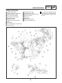
CABLE ROUTING
SPEC
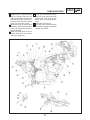
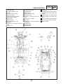
CABLE ROUTING
1
2
3
4
5
6
7
8
9
10
11
12
Starter motor cable
Battery negative (–) lead wire
Carburetor heater plug
A.C. generator coupler
Rear stop switch coupler
Neutral lead wire
Pickup lead wire
Side stand switch lead wire
T.P.S.
Tank fitting
#1 and #4 ignition coil lead wires
Horn lead wire
13
14
15
16
17
18
19
20
#3 high-tension cord
#4 high-tension cord
Engine frame ground lead wire
Rear stop switch
Relay assy
Guide wire
Fuel tank drain hose
Fuel tank breather hose
9
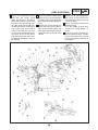
A Pass the starter motor cable and
the negative (–) lead wire of the
battery through the inside of the
seat rail.
CABLE ROUTING
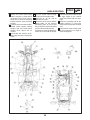
B Secure the carburetor heater
lead wire, the starter motor
cable, the negative (–) lead wire
of the battery, the A.C. generator
lead wire, the neutral lead wire,
the side stand switch lead wire,
the pickup lead wire, and the rear
stop switch lead wire (total 8
wires), to the fuel tank rail, near
the air cleaner intake port mounting screw, by use of this band.
The front end of the band must
be directed towards the front of
the vehicle.
C Clamp the throttle cables to the
fuel tank rail, on the tank fitting by
use of this band. The front end of
the band must be directed downward.
D Thread this clamp through the
upper hole in the gusset and secure the two throttle cables. The
front end of the clamp must be directed towards the inside of the
vehicle.
10
SPEC
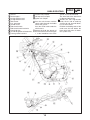
E Bundle the #3 and #4 high-tension cords, on the head cover
mounting bolt at the #3 cord, by
use of this band.
F Do not entangle the lead wires
and the hosing.
Pass the bundle of lead wires
and that of hosing orderly as
shown.
G Pass the air cleaner drain hose,
the fuel tank drain hose, and the
fuel tank breather hose (total 3
hoses) through the guide wire of
the engine.
CABLE ROUTING
H Bundle the A.C. generator lead K Clamp the wire harness to the
wire, the pickup lead wire, the
seat rail, at the front end of the
side stand switch lead wire, the
bracket.The front end of the
starter motor cable, and the carclamp must be directed downburetor heater lead wire (total 5
ward.
wires), by use of this clamp.
L Clamp the wire harness.
I Match the marks of the fuel tank M Pass the wire harness between
drain hose and fuel tank breather
the handle standing lug member
hose, and arrange the two types
and the rear fender.
of hose properly.
J Match the paint mark of the air
cleaner drain hose to the lower
end of the guide wire.
11
SPEC
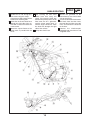
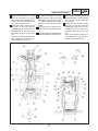
CABLE ROUTING
1
2
3
4
5
6
7
8
9
10
11
12
Gusset
13 Flasher relay coupler
Tension pipe 1
14 Oil lamp relay coupler
#2 high-tension cord
15 Igniter unit coupler
#1 high-tension cord
A Pass the wire harness and the
Wire starter
starter cable through the holder
A.C. generator
wire of the gusset.
Oil filter cover
Pass the starter cable under the
Side stand switch
wire harness.
Side stand switch lead wire
B Secure the lead wire branch of
Horn lead wire
the main harness to tension pipe
#2 and #3 ignition coil lead wires
1, at the immediate rear of the
Frame ground lead wire
12
SPEC
gusset, by use of this band.
The front end of the band must
be directed downward.
C Bundle the four high-tension
cords, the #1 and #2 cords up
and the #3 and #4 cords down,
by use of this band.
Position the leading ends of the
cords near, but not below, the
lower front end of the air induction system assy.
CABLE ROUTING
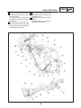
D Bundle the #1 and #2 high-ten- G After securing the side stand
sion cords using this clamp.
switch lead wire using this
Clamp these cords above the #2
clamp, first route the lead wire
head cover mounting bolt.
between the pickup cover, the oil
E Route the air cleaner drain hose
filter cover, the A.C. generator,
through the right side of the veand the starter motor. Next, as
hicle with a clearance above the
with the engine lead wire, route
starter motor.
the lead wire through the right
F Mount the square fixture of the
side of the vehicle.
clutch hose in parallel with the H Clamp the clutch hose.
cover.
13
SPEC
I Secure the grommet of the
clutch hose by use of this holder
wire of the gusset.
J Pass the horn lead wire between
the clutch hose and the frame,
then pull the lead wire out to the
front, and connect the lead wire
to the horn.
K Connect the black-couplerequipped lead wire to the #1 and
#4 ignition coils.
CABLE ROUTING
L Pass this clamp through the low- N Fasten the frame ground lead
er hole of the gusset and secure
wire together with the igniter unit
the clutch hose.
mounting screw.
The front end of the clamp must O Clamp the seat lock wire to the
be directed towards the inside of
seat rail.
the vehicle.
The front end of the clamp must
M Pass the main harness through
be directed downward.
the inside of the clutch hose and
insert the harness into the left of
the headlight lower hole.
14
SPEC
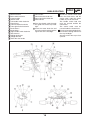
CABLE ROUTING
Throttle cable
#1 and #4 ignition coils
T.P.S.
Neutral switch coupler
Pickup coupler
Side stand switch coupler
Fuel sender coupler
Igniter unit
Starter cable
#2 and #3 ignition coils
Stoppers
Negative (–) lead wire of the battery
13 Relay assy
1
2
3
4
5
6
7
8
9
10
11
12
14
15
16
17
18
19
20
21
22
23
24
25
Starter motor cable
Thermoswitch
Starter relay
Rib of the rear fender
Seat lock wire
Positive (+) lead wire of the battery
Starter relay coupler
Fuse box
Negative (–) lead wire coupler of
the battery
Flasher relay
Oil lamp relay
Battery band
15
SPEC
A Right horn.
Install the HI tone source (with Hmarked label) at the right of the
vehicle.
B Connect the #1-#4 high-tension
cords in order of the cord number.
C Pass the T.P.S. lead wire through
the clamp of the #4 carburetor.
D To fuel sender
CABLE ROUTING
E Clamp the starter motor cable
and the negative (–) lead wire of
the battery to the seat rail, between the air cleaner mounting
bracket and the tank mounting
bracket.
F Connect the fuel sender coupler,
neutral switch coupler, pickup
coupler, and side stand switch
coupler wires above the air
cleaner.
G Thread the wire harness insertion clamp onto the T-stud of the
frame.
SPEC
H Pass the starter cable through K Connect the starter cable to face
the front of the throttle cable.
at right angles to the vehicle
I From left: #1, #2, #3, and #4
body with contact with the stophigh-tension cords.
pers.
J Secure the wire harness and the L Direct the crimping side of the
starter cable, on the harness
battery positive (+) lead wire
positioning tape, by use of this
downward and connect the lead
band. The front end of the band
wire.
must be directed downward.
M Connect the starter motor cable
The harness must not deflect beto face outward at an angle of
tween the T-stud and the clamp.
about 45 degrees.
16
CABLE ROUTING
N Secure the two positive (+) lead P Store the wire harness, the tailwires of the battery, the negalight lead wire, and the rear left
tive(–) lead wire coupler of the
and right flasher lead wires, into
battery, and the wire harness by
the space between the taillight
use of this battery band.
bracket and the rib of the rear
O Clamp the wire harness to the
fender.
seat rail, on the wire harness Q The seat lock wire must not expositioning tape and at the imtend to the outside of the brackmediate rear of the side cover
et.
mounting bracket on the seat R Pass the lead wire leading to the
rail.
fuse box under the wire harness.
The front end of the clamp must
face downward and be positioned inside the back stay.
17
SPEC
S After connecting the lead wire of
the thermoswitch, store the lead
wire into the space under the
wire harness.
T Clamp the wire harness to the
seat rail, on the wire harness
positioning tape and at the immediate rear of the side cover
mounting bracket on the seat
rail.
The front end of the clamp must
face downward and be positioned inside the back stay.
CABLE ROUTING
1
2
3
4
5
6
7
8
9
10
11
12
13
14
15
Meter lead wire
Main switch lead wire
Crown handle
Starter cable
Left handle switch lead wire
Clutch hose
Front left flasher lead wire
Front right flasher lead wire
Brake hose 2
Brake hose 1
Right handle switch lead wire
Wire harness
Taillight lead wires
Taillight bracket
Rib of the rear fender
16
17
18
19
Rear fender
Rear left flasher lead wire
Rear right flasher lead wire
Wire harness
A Pass the throttle cable through
the guide wire of the stay headlight.
B Insert the meter lead wire and
the main switch lead wire into the
upper hole of the headlight.
18
SPEC
C Bundle the handle switch lead
wire, the clutch hose, and the
starter cable, under the crown
handle, by use of this band.
The handle switch lead wire
must be passed outside the
clutch hose.
The starter cable must be
passed inside the clutch hose.
D Pass the front left and right flasher lead wires through the front of
the stay headlight.
Securely mount the cap to face
upward.
CABLE ROUTING
E Insert the left lead wire of the
handle switch and the left lead
wire of the front flasher into the
left of the headlight lower hole.
F Insert the right lead wire of the
handle switch and the right lead
wire of the front flasher into the
right of the headlight lower hole.
G Bundle the handle switch lead
wire and brake hose 2, near the
guide wire of the stay headlight
by use of this band.
SPEC
H Match the wire harness, the K The wire harness, the taillight
main switch lead wire, and the
lead wires, and the rear left and
meter lead wire, to the wire harright flasher lead wires must be
ness and main switch lead wire
arranged below the rib of the rear
positioning tapes, and bundle
fender.
the harness and the lead wires L Clamp the wire harness and the
by use of the band.
rear left and right flasher lead
I The lead wires must be clamped
wires.
in this area.
The front end of the clamp must
J Bundle the front left and right
be directed forward.
flasher lead wires by use of the M Pass the rear left and right flashclamp.
er lead wires through the respective holes in the rear fender.
19
CHK
ADJ
INTRODUCTION/
PERIODIC MAINTENANCE/LUBRICATION INTERVALS
PERIODIC INSPECTION AND ADJUSTMENT
INTRODUCTION
This chapter includes all information necessary to perform recommended inspections and adjustments. These preventive maintenance procedures, if followed, will ensure more reliable vehicle operation and a longer service life. The need for costly overhaul work will be greatly reduced. This information applies to vehicles already in service as well as new vehicles that are being prepared for sale. All
service technicians should be familiar with this entire chapter.
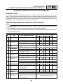
PERIODIC MAINTENANCE/LUBRICATION INTERVALS
NOTE:
" The annual checks must be performed every year, except if a kilometer-based maintenance is performed instead.
" From 50,000 km, repeat the maintenance intervals starting from 10,000 km.
" Items marked with an asterisk should be performed by Yamaha dealer as they require special tools,
data and technical skills.
NO
NO.
ITEM
CHECK OR MAINTENANCE JOB
1
*
Fuel line
! Check fuel hoses and vacuum hose for
cracks or damage.
2
*
Fuel filter
! Check condition.
p
p
g
Spark
plugs
! Check condition.
! Clean and regap.
3
ODOMETER READING (" 1,000 km)
1
10
20
30
40
ANNUAL
CHECK
√
√
√
√
√
√
√
*
Air filter element
5
6
7
Valves
*
*
Clutch
Front brake
! Check valve clearance.
! Adjust
*
Rear brake
√
! Clean.
√
! Check operation, fluid level and vehicle for
fluid leakage. (See NOTE.)
√
√
√
√
√
! Check operation, fluid level and vehicle for
fluid leakage. (See NOTE.)
√
√
√
√
√
√
Whenever worn to the limit
! Check operation, fluid level and vehicle for
fluid leakage. (See NOTE.)
√
√
√
√
√
√
Whenever worn to the limit
! Check for cracks or damage.
9
*
Brake hoses
10
*
Wheels
! Check runout and for damage.
√
√
√
√
√
√
√
√
√
√
√
√
√
√
√
√
! Replace. (See NOTE.)
√
√
√
Every 4 years
Check tread depth and for damage.
Replace if necessary.
Check air pressure.
Correct if necessary.
11
*
Tires
!
!
!
!
12
*
Wheel bearings
! Check bearing for looseness or damage.
√
13
*
Swingarm
! Check operation and for excessive play.
√
Drive chain
√
√
! Replace.
! Replace brake pads.
14
√
Every 20,000 km
! Replace brake pads.
8
√
√
! Replace.
4
√
! Lubricate with lithium-soap-based grease.
Every 50,000 km
! Check chain slack.
! Make sure that the rear wheel is properly
aligned.
! Clean and lubricate.
Every 1,000 km and after washing
the motorcycle or riding in the rain
20
√
CHK
ADJ
PERIODIC MAINTENANCE/LUBRICATION INTERVALS
NO
NO.
15
ITEM
*
g bearings
g
Steering
CHECK OR MAINTENANCE JOB
! Check bearing play and steering for
roughness.
ODOMETER READING (" 1,000 km)
1
10
20
30
40
√
√
√
√
√
! Lubricate with lithium-soap-based grease.
16
*
17
ANNUAL
CHECK
Every 20,000 km
Chassis fasteners
! Make sure that all nuts, bolts and
screws are properly tightened.
√
√
√
√
√
Sidestand,
centeratand
! Check operation.
! Lubricate.
√
√
√
√
√
√
√
√
√
√
√
18
*
Sidestand switch
! Check operation.
19
*
Front fork
! Check operation and for oil leakage.
√
√
√
√
20
*
Shock absorber
assemblies
! Check operation and shock absorbers for
oil leakage.
√
√
√
√
21
*
Carburetors
! Check starter (choke) operation.
! Adjust engine idling speed and
synchronization.
√
√
√
√
√
√
22
Engine oil
! Change.
! Check oil level and vehicle for oil leakage.
√
√
√
√
√
√
23
Engine oil filter
element
! Replace.
√
Front and rear
brake switches
! Check operation.
√
Moving parts and
cables
! Lubricate.
Lights, signals
and switches
! Check operation.
! Adjust headlight beam.
24
*
25
26
*
√
√
√
√
√
√
√
√
√
√
√
√
√
√
√
√
√
√
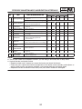
NOTE:
" The air filter needs more frequent service if you are riding in unusually wet or dusty areas.
" Hydraulic brake and clutch service.
! Regularly check and, if necessary, correct the brake and clutch fluid levels.
! Every two years replace the internal components of the brake master cylinders and calipers as
well as clutch master and release cylinders, and change the brake and clutch fluids.
! Replace the brake and clutch hoses every four years and if cracked or damaged.
21
ADJUSTING THE CLUTCH LEVER
CHK
ADJ
ENGINE
EAS00082
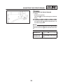
ADJUSTING THE CLUTCH LEVER
1. Adjust:
! clutch lever position
(distance a from the handlebar grip to the
clutch lever)
a. While pushing the clutch lever forward, turn
the adjusting dial 1 until the clutch lever is in
the desired position.
NOTE:
Be sure to align the setting on the adjusting dial
with the arrow mark 2 on the clutch lever holder.
Position #1
Position #5
22
Distance a is the largest
Distance a is the smallest
ADJUSTING THE FRONT BRAKE
CHK
ADJ
EAS00107
CHASSIS
ADJUSTING THE FRONT BRAKE
1. Adjust:
! brake lever position
(distance a from the throttle grip to the brake
lever)
a. While pushing the brake lever forward, turn
the adjusting dial 1 until the brake lever is in
the desired position.
NOTE:
Be sure to align the setting on the adjusting dial
with the arrow mark 2 on the brake lever holder.
Position #1
Position #5
23
Distance a is the largest.
Distance a is the smallest.
AIR INDUCTION SYSTEM
CARB
CARBURETOR
EAS00507
AIR INDUCTION SYSTEM
AIR INJECTION
The air induction system burns unburned exhaust gases by injecting fresh air (secondary
air) into the exhaust port, reducing the emission
of hydrocarbons.
When there is negative pressure at the exhaust
port, the reed valve opens, allowing secondary
air to flow into the exhaust port. The required
temperature for burning the unburned exhaust
gases is approximately 600 to 700#C.
EAS00508
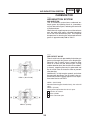
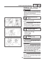
AIR CUTOFF VALVE
The air cutoff valve is operated by the intake gas
pressure through the piston valve diaphragm.
Normally, the air cutoff valve is open to allow
fresh air to flow into the exhaust port. During
sudden deceleration (the throttle valve suddenly closes), negative pressure is generated and
the air cutoff valve is closed in order to prevent
after-burning.
Additionally, at high engine speeds and when
the pressure decreases, the air cutoff valve automatically closes to guard against a loss of performance due to self-EGR.
VIEW 1. (NO FLOW)
VIEW 1. (NO FLOW)
When decelerating (the throttle closes), the valve will
close.
VIEW 2. (FLOW)
During normal operation the valve is open.
A From the air cleaner
B To the cylinder
C To the carburetor joint
VIEW 2. (FLOW)
24
AIR INDUCTION SYSTEM
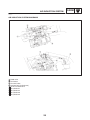
EAS00509
AIR INDUCTION SYSTEM DIAGRAMS
1
2
3
4
A
B
C
D
E
Reed valve
Air cleaner
Air cutoff valve
Vacuum hose (cylinder #3)
To the air cutoff valve
To cylinder #1
To cylinder #2
To cylinder #3
To cylinder #4
25
CARB
AIR INDUCTION SYSTEM
CARB
EAS00510
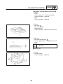
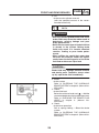
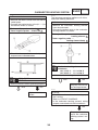
CHECKING THE AIR INDUCTION SYSTEM
1. Check:
! hoses
Loose connection ! Connect properly.
Cracks/damage ! Replace.
! pipes
Cracks/damage ! Replace.
2. Check:
! fibre reed 1
! fibre reed stopper
! reed valve seat
Cracks/damage ! Replace the reed valve.
3. Measure:
! fibre reed bending limit a
Out of specification ! Replace the reed
valve.
Fibre reed bending limit
0.2 mm
1 Surface plate
4. Check:
! air cutoff valve
Cracks/damage ! Replace.
26
FRONT AND REAR BRAKES
CHAS
CHASSIS
FRONT AND REAR BRAKES
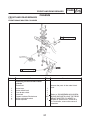
EAS00586
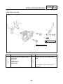
FRONT BRAKE MASTER CYLINDER
10 Nm (1.0 m!kg)
30 Nm (3.0 m!kg)
Order
Job/Part
Q’ty
Removing the front brake master
cylinder
Brake fluid
1
2
3
4
5
6
7
Remarks
Remove the parts in the order listed.
Drain
1
2
1
1
3/2
1
1
Brake lever
Brake switch lead
Front brake switch
Union bolt
Copper washers/Brake hose
Master cylinder bracket
Master cylinder
27
Refer to “DISASSEMBLING/ASSEMBLING AND INSTALLING THE REAR
BRAKE MASTER CYLINDER” in
chapter 6. (Manual No.: 5EA3-AE1)
For installation, reverse the removal
procedure.
FRONT AND REAR BRAKES
CHAS
EAS00598
ASSEMBLING AND INSTALLING
FRONT BRAKE MASTER CYLINDER
THE
WARNING
! Before installation, all internal brake components should be cleaned and lubricated
with clean or new brake fluid.
! Never use solvents on internal brake components.
Recommended brake fluid
DOT 4
1. Install:
! brake master cylinder 1
NOTE:
! Install the brake master cylinder holder with
the “UP” mark facing up.
! Align the end of the brake master cylinder holder with the punch mark a on the handlebar.
! First, tighten the upper bolt, then the lower bolt.
Brake master cylinder bolt
10 Nm (1.0 m!kg)
2. Install:
! copper washers (New) 1
! brake hose 1 2
! brake hose 2 3
! union bolt 4
Union bolt
30 Nm (3.0 m!kg)
WARNING
Proper brake hose routing is essential to insure safe motorcycle operation. Refer to
“CABLE ROUTING”.
CAUTION:
! When installing the brake hose 1 2 onto
the brake master cylinder, make sure that
the brake pipe touches the projection a as
shown. And install the paint mark b toward the brake master cylinder side.
! Install the brake hose 2 3 at the same
angle as the brake hose 1 2 .
NOTE:
Turn the handlebar to the left and to the right to
make sure that the brake hose does not touch
other parts (e.g., wire harness, cables, leads).
Correct if necessary.
28
FRONT AND REAR BRAKES
CHAS
3. Fill:
! brake master cylinder reservoir
(with the specified amount of the recommended brake fluid)
Recommended brake fluid
DOT 4
WARNING
! Use only the designated brake fluid. Other
brake fluids may cause the rubber seals to
deteriorate, causing leakage and poor
brake performance.
! Refill with the same type of brake fluid that
is already in the system. Mixing brake
fluids may result in a harmful chemical
reaction, leading to poor brake performance.
! When refilling, be careful that water does
not enter the reservoir. Water will significantly lower the boiling point of the brake
fluid and could cause vapor lock.
CAUTION:
Brake fluid may damage painted surfaces
and plastic parts. Therefore, always clean
up any spilt brake fluid immediately.
4. Bleed:
! brake system
Refer to “BLEEDING THE HYDRAULIC
BRAKE SYSTEM” in chapter 3. (Manual No.:
5EA3-AE1)
5. Check:
! brake fluid level
Below the minimum level mark a ! Add the
recommended brake fluid to the proper level.
Refer to “CHECKING THE BRAKE FLUID
LEVEL” in chapter 3. (Manual No.:
5EA3-AE1)
6. Check:
! brake lever operation
Soft or spongy feeling ! Bleed the brake
system.
Refer to “BLEEDING THE HYDRAULIC
BRAKE SYSTEM” in chapter 3. (Manual No.:
5EA3-AE1)
29
FRONT AND REAR BRAKES
CHAS
EAS00616
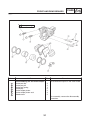
REAR BRAKE CALIPER
30 Nm (3.0 m!kg)
40 Nm (4.0 m!kg)
Order
1
2
3
4
Job/Part
Q’ty
Removing the rear brake caliper
Brake fluid
Union bolt
Copper washer
Brake hose
Brake caliper
Remarks
Remove the parts in the order listed.
Drain.
1
2
1
1
For installation, reverse the removal
procedure.
30
FRONT AND REAR BRAKES
CHAS
EAS00617
6 Nm (0.6 m!kg)
Order
Job/Part
Q’ty
1
2
3
4
5
6
7
Disassembling the rear brake caliper
Brake pad clip
Brake pad pin
Brake pad spring
Brake pad
Brake caliper piston
Brake caliper piston seal
Bleed screw
Remarks
Disassemble the parts in the order listed.
4
2
1
2
2
4
2
For assembly, reverse the disassembly
procedure.
31
CARBURETOR HEATING SYSTEM
ELEC
ELECTRICAL
CARBURETOR HEATING SYSTEM
2
3
5
6
14
51
52
53
32
Fuse (main)
Battery
Main switch
Fuse (ignition)
Neutral switch
Carburetor heater relay
Thermo switch
Carburetor heater
ELEC
CARBURETOR HEATING SYSTEM
EAS00821
EAS00749
TROUBLESHOOTING
3. Main switch
The carburetor heating system fails to operate.
! Check the main switch for continuity.
Refer to “CHECKING THE SWITCHES” in
chapter 8. (Manual No.: 5EA3-AE1)
Check:
1. Main and ignition fuses
2. Battery
3. Main switch
4. Neutral switch
5. Carburetor heater relay
6. Thermo switch
7. Carburetor heater
8. Wiring connections
(of the entire carburetor heating system)
! Is the main switch OK?
YES
Replace the main
switch.
EAS00751
4. Neutral switch
NOTE:
Before troubleshooting, remove the following
part(-s):
1) Rider and passenger seats
Troubleshoot with the following special tool(-s).
! Check the neutral switch for continuity.
Refer to “CHECKING THE SWITCHES” in
chapter 8. (Manual No.: 5EA3-AE1)
! Is the neutral switch OK?
YES
Pocket tester
90890-03112
NO
Replace the neutral
switch.
EAS00738
1. Main, and ignition fuses
! Check the main and ignition fuses for continuity.
Refer to “CHECKING THE FUSES” in chapter 3. (Manual No.: 5EA3-AE1)
EAS00822
5. Carburetor heater relay
! Disconnect the carburetor heater relay coupler from the wire harness.
! Connect the pocket tester (Ω " 1) to the carburetor heater relay coupler as shown.
! Are the main and ignition fuses OK?
YES
NO
NO
Tester positive probe ! red/white 1
Tester negative probe ! black 2
Replace the fuse(-s).
EAS00739
2. Battery
! Check the condition of the battery.
Refer to “CHECKING THE BATTERY” in
chapter 3. (Manual No.: 5EA3-AE1)
Open-circuit voltage
12.8 V or more at 20#C
! Check the carburetor heater relay for no
continuity.
! Is the carburetor heater relay OK?
! Is the battery OK?
YES
NO
! Clean the battery
terminals.
! Recharge or replace the battery.
YES
NO
Replace the carburetor heater relay.
33
CARBURETOR HEATING SYSTEM
ELEC
EAS00825
6. Thermo switch
The following procedure applies to all of the
carburetor heating elements.
! Remove the thermo switch from the thermo
switch plate.
! Connect the pocket tester to the (Ω " 1) to
the thermo switch as shown.
7. Carburetor heater
! Remove the carburetor heating element
from the carburetor.
! Connect the pocket tester to the carburetor
heating element as shown.
Tester positive probe ! black 1
Tester negative probe ! black/red 2
Tester positive probe !
heating element 1
Tester negative probe !
heating element body 2
! Check the thermo switch for continuity at the
temperatures indicated below.
11#C
OFF
! Measure the carburetor heater resistance.
Carburetor heating element
resistance
12 V 15 W: 4 ! 11 Ω at 20#C
12 V 20 W: 4 ! 11 Ω at 20#C
ON
16#C
! Is the carburetor heating element OK?
A COOL DOWN
YES
B HEAT UP
! Does the thermo switch operated properly?
YES
NO
Replace the carburetor heating element.
NO
EAS00826
8. Wiring
Replace the thermo
switch.
! Check the entire carburetor heating system’s wiring.
Refer to “CIRCUIT DIAGRAM”.
! Is the carburetor heating system’s wiring
properly connected and without defects?
NO
Properly connect or
repair the carburetor
heating system’s wiring.
34
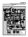
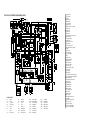
XJR1300 2002 WIRING DIAGRAM (for EUR)
1
2
3
4
5
6
7
8
9
10
11
12
13
14
15
COLOR CODE
B .....
Br . . . .
Ch . . .
Dg . . .
G ....
Gy . . .
L .....
Lg . . . .
Black
Brown
Chocolate
Dark green
Green
Gray
Blue
Light green
O ....
Sb . . . .
P .....
R.....
Y .....
B/ L . . .
B/ R . .
B/ Y . .
Orange
Sky blue
Pink
Red
Yellow
Black/ Blue
Black/ Red
Black/ Yellow
Br/ L . .
Br/ W .
G/Y . .
L/B . . .
L/R . .
L/W . .
L/Y . . .
R/ B . .
Brown/ Blue
Brown/ White
Green / Yellow
Blue/ Black
Blue/ Red
Blue/ White
Blue/ Yellow
Red/ Black
R/ L . .
R/ W . .
R/ Y . .
W/ G . .
W/ R . .
Y/ B . .
Red/ Blue
Red/ White
Red/ Yellow
White/ Green
White/ Red
Yellow/ Black
16
17
18
19
20
21
22
23
24
25
26
27
28
29
30
31
32
33
34
35
36
37
38
39
40
41
42
43
44
45
46
47
48
49
50
51
52
53
54
55
AC generator
Fuse (main)
Battery
Starter relay
Main switch
Fuse (ignition)
Starter motor
Starting circuit cut-off relay
Ignitor unit
Ignition coil
Spark plug
Pickup coil
TPS (throttle position sensor)
Neutral switch
Sidestand switch
Start switch
Engine stop switch
Lights switch
Front brake switch
Handlebar switches (right)
Alarm
Fuse (turn)
Fuse (signal)
Fuse (headlight)
Horn
Flasher relay
Rear brake switch
Oil level relay
Oil level switch
Meter assembly
Speedometer
Neutral indicator light
Tachometer
Fuel gauge
Meter lights
Turn signal indicator light (left)
Turn signal indicator light (right)
Oil warning light
High beam indicator light
Fuel sender
Auxiliary light
Tail/ brake light
Clutch switch
Hazard switch
Turn signal switch
Horn switch
Dimmer switch
Pass switch
Handlebar switch (left)
Headlight
Carburetor heater relay
Thermo switch
Carburetor heater
Rear turn signal lights
Front turn signal lights
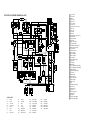
XJR1300P 2002 WIRING DIAGRAM (for AUS)
1
2
3
4
5
6
7
8
9
10
11
12
13
14
15
COLOR CODE
B .....
Br . . . .
Ch . . .
Dg . . .
G ....
Gy . . .
L .....
Lg . . . .
Black
Brown
Chocolate
Dark green
Green
Gray
Blue
Light green
O ....
Sb . . . .
P .....
R.....
Y .....
B/ L . . .
B/ R . .
B/ Y . .
Orange
Sky blue
Pink
Red
Yellow
Black/ Blue
Black/ Red
Black/ Yellow
Br/ L . .
Br/ W .
G/Y . .
L/B . . .
L/R . .
L/W . .
L/Y . . .
R/ B . .
Brown/ Blue
Brown/ White
Green / Yellow
Blue/ Black
Blue/ Red
Blue/ White
Blue/ Yellow
Red/ Black
R/ L . .
R/ W . .
R/ Y . .
W/ G . .
W/ R . .
Y/ B . .
Red/ Blue
Red/ White
Red/ Yellow
White/ Green
White/ Red
Yellow/ Black
16
17
18
19
20
21
22
23
24
25
26
27
28
29
30
31
32
33
34
35
36
37
38
39
40
41
42
43
44
45
46
47
48
49
50
AC generator
Fuse (main)
Battery
Starter relay
Main switch
Fuse (ignition)
Starter motor
Starting circuit cut-off relay
Ignitor unit
Ignition coil
Spark plug
Pickup coil
TPS (throttle position sensor)
Neutral switch
Sidestand switch
Start switch
Engine stop switch
Front brake switch
Handlebar switches (right)
Carburetor heater relay
Thermo switch
Carburetor heater
Fuse (signal)
Fuse (headlight)
Meter assembly
Speedometer
Neutral indicator light
Tachometer
Fuel gauge
Meter lights
Turn signal indicator light (left)
Turn signal indicator light (right)
Oil warning light
High beam indicator light
Fuel sender
Oil level relay
Oil level switch
Rear brake switch
Tail/ brake light
Flasher relay
Horn
Handlebar switch (left)
Pass switch
Dimmer switch
Horn switch
Turn signal switch
Clutch switch
Headlight
Rear turn signal lights
Front turn signal lights


![Manuale Officina [ ITA ] Yamaha R1 2002-2003](http://vs1.manualzilla.com/store/data/006110674_1-52d32bbc9127defc0419b49b1226ec2b-150x150.png)